
MS-7623 V4.1 - Motherboard MSI - Free user manual and instructions
Find the device manual for free MS-7623 V4.1 MSI in PDF.

| Product Type | Micro-ATX Motherboard |
| Brand | MSI |
| Model | MS-7623 V4.1 (880GMA-E53) |
| Supported Processors | AMD Phenom II / Phenom / Athlon II / Athlon / Sempron (socket AM3) |
| Chipset | Northbridge AMD 880G, Southbridge AMD SB710 |
| Supported Memory | DDR3 800/1066/1333/1600* (OC) up to 16 GB, dual channel |
| Network Connector | Realtek RTL8111E Gigabit Ethernet |
| Audio | Realtek ALC892, 8-channel HD |
| Storage | 1 IDE port (SB710), 6 SATA 3 Gb/s ports (SB710), 2 SATA 6 Gb/s ports (Marvell SE9128), 1 floppy drive port |
| Rear Connectors | 1 PS/2 combo, 1 VGA, 1 DVI-D, 1 HDMI, 1 S/PDIF optical, 1 IEEE 1394, 4 USB 2.0, 2 USB 3.0, 1 RJ45, 6 audio jacks |
| Internal Connectors | 1 parallel, 1 serial, 3 USB 2.0, 1 IEEE 1394, 1 S/PDIF out, 1 front audio, 1 CD-In, 1 TPM, 1 OC switch, 1 chassis intrusion |
| Expansion Slots | 1 PCIe x16, 2 PCIe x1, 1 PCI |
| Dimensions | 24.4 cm x 24.4 cm (Micro-ATX) |
| Power Supply | ATX 24-pin + ATX 4-pin (CPU) |
| Main Features | Overclocking via OC Genie, FSB/voltage settings, Cool'n'Quiet support, APS technology |
| Maintenance and Cleaning | Dust regularly with a soft dry cloth; avoid moisture and liquid cleaners |
| Safety | Turn off and unplug before handling; follow electrical standards; do not touch live components |
| Spare Parts and Repairability | Available on MSI website; the motherboard contains no user-repairable parts (except CMOS) |
| General Information | Manual downloadable as PDF from notice-facile.com; compatible with Windows and Linux |
Frequently Asked Questions - MS-7623 V4.1 MSI
User questions about MS-7623 V4.1 MSI
0 question about this device. Answer the ones you know or ask your own.
Ask a new question about this device
Download the instructions for your Motherboard in PDF format for free! Find your manual MS-7623 V4.1 - MSI and take your electronic device back in hand. On this page are published all the documents necessary for the use of your device. MS-7623 V4.1 by MSI.
USER MANUAL MS-7623 V4.1 MSI
FCC-B RADIO FREQUENCY INTERFERENCE STATEMENT
This equipment has been tested and found to comply with the limits for a class B digital device, pursuant to part 15 of the FCC rules. These limits are designed
to provide reasonable protection against harmful interference in a residential installation. This equipment generates, uses and can


N1996
radiate radio frequency energy and, if not installed and used in accordance with the instruction manual, may cause harmful interference to radio communications. However, there is no guarantee that interference will occur in a particular installation. If this equipment does cause harmful interference to radio or television reception, which can be determined by turning the equipment off and on, the user is encouraged to try to correct the interference by one or more of the measures listed below.
Reorient or relocate the receiving antenna.
Increase the separation between the equipment and receiver.
Connect the equipment into an outlet on a circuit different from that to which the receiver is connected.
Consult the dealer or an experienced radio/ television technician for help.
Notice 1
The changes or modifications not expressly approved by the party responsible for compliance could void the user's authority to operate the equipment.
Notice 2
Shielded interface cables and A.C. power cord, if any, must be used in order to comply with the emission limits.
VOIR LA NOTICE D'INSTALLATION AVANT DE RACCORDER AU RESEAU.

Micro-Star International MS-7623
This device complies with Part 15 of the FCC Rules. Operation is subject to the following two conditions:
(1) this device may not cause harmful interference, and
(2) this device must accept any interference received, including interference that may cause undesired operation.
PART NUMBER
G52-76231XJ
COPYRIGHT NOTICE
The material in this document is the intellectual property of MICRO-STAR INTERNATIONAL. We take every care in the preparation of this document, but no guarantee is given as to the correctness of its contents. Our products are under continual improvement and we reserve the right to make changes without notice.
TRADEMARKS
All trademarks are the properties of their respective owners.
MSI is registered trademark of Micro-Star Int'l Co., Ltd.
NVIDIA® is registered trademark of NVIDIA Corporation.
ATI® is registered trademark of ATI Technologies, Inc.
AMD is registered trademarks of AMD Corporation.
Intel is registered trademarks of Intel Corporation.
Windows® is registered trademarks of Microsoft Corporation.
AMI is registered trademark of American Megatrends, Inc.
Award® is a registered trademark of Phoenix Technologies Ltd.
Sound Blaster® is registered trademark of Creative Technology Ltd.
Realtek® is registered trademark of Realtek Semiconductor Corporation.
■ JMicron® is registered trademark of JMicron Technology Corporation.
Netware is a registered trademark of Novell, Inc.
REVISION HISTORY
| Revision | Revision History | Date |
| V4.0 | First release | July 2010 |
| V4.1 | Update specification | August 2010 |
SAFETY INSTRUCTIONS
Always read the safety instructions carefully.
- Keep this User Manual for future reference.
- Keep this equipment away from humidity.
Lay this equipment on a reliable flat surface before setting it up.
- The openings on the enclosure are for air convection hence protects the equipment from overheating. Do not cover the openings.
- Make sure the voltage of the power source is at 110/220V before connecting.
- Place the power cord such a way that people can not step on it. Do not place anything over the power cord.
Always Unplug the Power Cord before inserting any add-on card or module.
All cautions and warnings on the equipment should be noted.
- Never pour any liquid into the opening that can cause damage or cause electrical shock.
If any of the following situations arises, get the equipment checked by service personnel:
The power cord or plug is damaged.
Liquid has penetrated into the equipment.
The equipment has been exposed to moisture.
The equipment does not work well or you can not get it work according to User Manual.
The equipment has been dropped and damaged.
The equipment has obvious sign of breakage.
DO NOT LEAVE THIS EQUIPMENT IN AN ENVIRONMENT UNCONDITIONED, STORAGE TEMPERATURE ABOVE 60^ (140^) , IT MAY DAMAGE THE EQUIPMENT.
CAUTION
Danger of explosion if battery is incorrectly replaced.
警告使用者
For better environmental protection, waste batteries should be collected separately for recycling or special disposal.
ENGLISH
To protect the global environment and as an environmentalist, MSI must remind you that...
Under the European Union ("EU") Directive on Waste Electrical and Electronic Equipment, Directive 2002/96/EC, which takes effect on August 13, 2005, products of "electrical and electronic equipment"

cannot be discarded as municipal wastes anymore, and manufacturers of covered electronic equipment will be obligated to take back such products at the end of their useful life. MSI will comply with the product take back requirements at the end of life of MSI-branded products that are sold into the EU. You can return these products to local collection points.
DEUTSCH
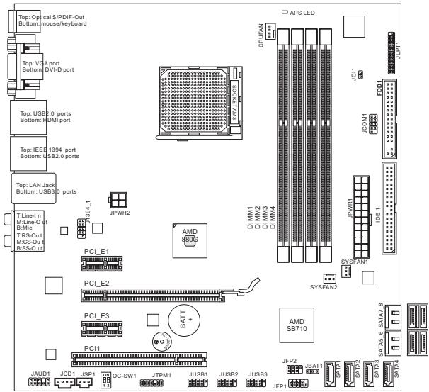
Thank you for choosing the 880GMA-E53 series (MS-7623 v4.x) Micro-ATX mainboard. The 880GMA-E53 series is design based on AMD® 880G & SB710 chipset for optimal system efficiency. Designed to fit the advanced AMD® AM3 processor, the 880GMA-E53 series deliver a high performance and professional desktop platform solution.

Layout
SPECIFICATIONS
Processor Support
- AMD® PhenomII/ Phenom/ Althon II/ Althon/ Sempron processors in AM3 package.
(For the latest information about CPU, please visit
http://www.msi.com/index.php?func=cpuform2)
HyperTransport
Supports Hyper Transport(HT) 3.0 Technology
Chipset
North Bridge: AMD® 880G chipset
South Bridge: AMD® SB710 chipset
Memory Support
DDR3 800/1066/1333/1600*(OC)SDRAM(16GB Max)
Supports Dual-Channel mode) (For more information on compatible components, please visit http://www.msi.com/index.php?func testreport)
LAN
Supports LAN 10/100/1000 Fast Ethernet by Realtek® RTL8111E
Audio
Chip integrated by Realtek ALC892
Flexible 8-channel audio with jack sensing
Compliant with Azalia 1.0 Spec
IDE
1 IDE port by AMD® SB710
Supports Ultra DMA 33/66/100, PIO & Bus Master operation mode
SATA
6 SATA 3Gb/s ports by AMD® SB710 (SATA1~6)
2 SATA 6Gb/s ports by Marvell® SE9128 (SATA7~8)
Floppy
1 floppy port
Supports 1 FDD with 360KB, 720KB, 1.2MB, 1.44MB and 2.88MB
Connectors
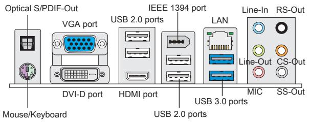
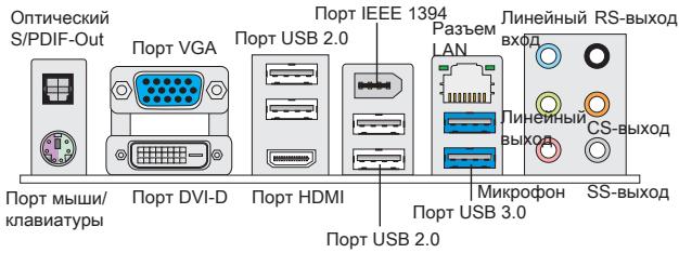
Back panel
- 1 Optical S/PDIF-Out
- 1 PS/2 mouse/keyboard port
- 1 VGA port
- 1 DVI-D port
- 1 HDMI port
- 1 IEEE 1394 port
- 4 USB 2.0 Ports
- 2 USB 3.0 ports
- 1 LAN jack
- 6 flexible audio jacks
On-Board Connectors
- 1 Parallel connector
- 3 USB 2.0 connectors
- 1 IEEE 1394 connector
- 1 Serial port connector
- 1 SPDIF-Out connector
- 1 Front Panel Audio connector
- 1 Chassis Intrusion connector
- 1 CD-In connector
- 1 TPM connector
- 1 OC switch
Slots
1 PCIE x16 slot
2 PCIE x1 slots
1 PCI slot, support 3.3V/5V PCI bus Interface
Form Factor
Micro-ATX (24.4cm X 24.4 cm)
Mounting
8 mounting holes
(If you need to purchase accessories and request the part numbers, you could search the product web page and find details on our web address below http://www.msi.com/index.php)
The rear panel provides the following connectors:
HARDWARE SETUP
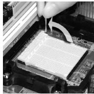
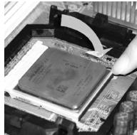
CPU & Cooler Installation for AM3
When you are installing the CPU, make sure the CPU has a cooler attached on the top to prevent overheating. Meanwhile, do not forget to apply some thermal paste on CPU before installing the heat sink/cooler fan for better heat dispersion.
The surface of AM3 CPU.
Remember to apply some thermal paste on it for better heat dispersion.

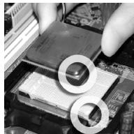
Follow the steps below to install the CPU & cooler correctly. Wrong installation will cause the damage of your CPU & mainboard.
- Pull the lever sideways away from the socket. Make sure to raise the lever up to a 90-degree angle.
- Look for the gold arrow of the CPU. The gold arrow should point as shown in the picture. The CPU can only fit in the correct orientation.
- If the CPU is correctly installed, the pins should be completely embedded into the socket and can not be seen. Please note that any violation of the correct installation procedures may cause permanent damages to your mainboard.
- Press the CPU down firmly into the socket and close the lever. As the CPU is likely to move while the lever is being closed, always close the lever with your fingers pressing tightly on top of the CPU to make sure the CPU is properly and completely embedded into the socket.
- Position the cooling set onto the retention mechanism. Hook one end of the clip to hook first.
- Then press down the other end of the clip to fasten the cooling set on the top of the retention mechanism. Locate the Fix Lever and lift up it.
- Fasten down the lever.
- Attach the CPU Fan cable to the CPU fan connector on the mainboard.


IMPORTANT
- Mainboard photos shown in this section are for demonstration of the cooler installation for Socket AM3 CPUs only. The appearance of your mainboard may vary depending on the model you purchase.
- While disconnecting the Safety Hook from the fixed bolt, it is necessary to keep an eye on your fingers, because once the Safety Hook is disconnected from the fixed bolt, the fixed lever will spring back instantly.
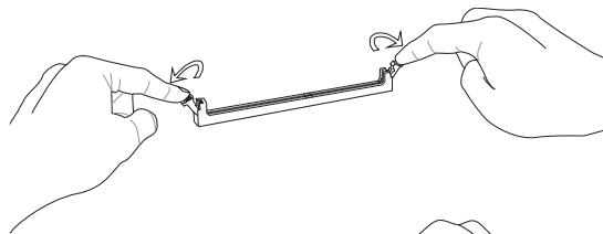
Installing Memory Modules
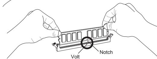
- The memory module has only one notch on the center and will only fit in the right orientation.
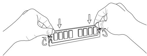
- Insert the memory module vertically into the DIMM slot. Then push it in until the golden finger on the memory module is deeply inserted in the DIMM slot. You can barely see the golden finger if the memory module is properly inserted in the DIMM slot.
- Manually check if the memory module has been locked in place by the DIMM slot clips at the sides.
IMPORTANT
- In Dual-Channel mode, make sure that you install memory modules of the same type and density in different channel DIMM slots.
- To ensure a successful system boot-up, always insert the memory modules into the DIMM1 first.
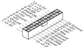
ATX 24-Pin Power Connector: JPWR1
This connector allows you to connect an ATX 24-pin power supply. To connect the ATX 24-pin power supply, make sure the plug of the power supply is inserted in the proper orientation and the pins are aligned. Then push down the power supply firmly into the connector.
ATX 4-Pin Power Connector: JPWR2
This 4-Pin power connector is used to provide power to the CPU.
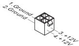
IMPORTANT
Make sure that all the connectors are connected to proper ATX power supplies to ensure stable operation of the mainboard.
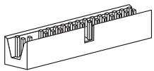
Floppy Disk Drive Connector: FDD1
This connector supports 360KB, 720KB, 1.2MB, 1.44MB or 2.88MB floppy disk drive.
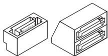
IDE Connector: IDE1
This connector supports IDE hard disk drives, optical disk drives and other IDE devices.
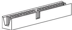
IMPORTANT
If you install two IDE devices on the same cable, you must configure the drives to cable select mode or separately to master / slave mode by setting jumpers. Refer to IDE device documentation supplied by the vendors for jumper setting instructions.
Serial ATA Connector: SATA1 ~ 8
This connector is a Serial ATA interface port. Each connector can connect to one Serial ATA device.
IMPORTANT
Please do not fold the Serial ATA cable into a 90-degree angle. Otherwise, data loss may occur during transmission.
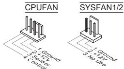
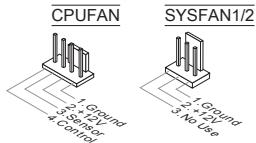
Fan Power Connectors: CPUFAN, SYSFAN1, SYSFAN2
The fan power connectors support system cooling fan with +12V . When connecting the wire to the connectors, always note that the red wire is the positive and should be connected to the +12V ; the black wire is Ground and should be connected to GND. If the mainboard has a System Hardware Monitor chipset onboard, you must use a specially designed fan with speed sensor to take advantage of the CPU fan control.
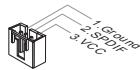
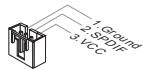
S/PDIF-Out Connector: JSP1
This connector is used to connect S/PDIF (Sony & Philips Digital Interconnect Format) interface for digital audio transmission.
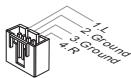
CD-In Connector: JCD1
This connector is provided for external audio input.
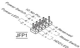
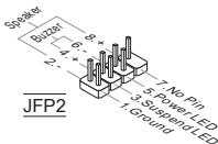
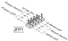
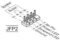
Front Panel Connectors: JFP1, JFP2
These connectors are for electrical connection to the front panel switches and LEDs. The JFP1 is compliant with Intel® Front Panel I/O Connectivity Design Guide.
Serial Port Connector: JCOM1
This connector is a 16550A high speed communication port that sends/receives 16 bytes FIFOs. You can attach a serial device.

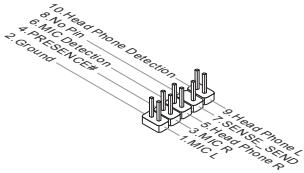
Front Panel Audio Connector: JAUD1
This connector allows you to connect the front panel audio and is compliant with Intel® Front Panel I/O Connectivity Design Guide.
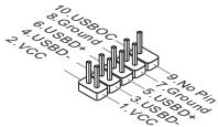
Front USB Connector: JUSB1, JUSB2, JUSB3
This connector, compliant with Intel® I/O Connectivity Design Guide, is ideal for connecting high-speed USB interface peripherals such as USB HDD, digital cameras, MP3 players, printers, modems and the like.
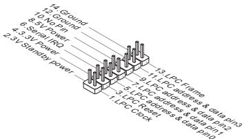
TPM Module connector: JTPM1
This connector connects to a TPM (Trusted Platform Module) module. Please refer to the TPM security platform manual for more details and usages.
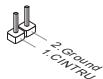
Chassis Intrusion Connector: JCI1
This connector connects to the chassis intrusion switch cable. If the chassis is opened, the chassis intrusion mechanism will be activated. The system will record this status and show a warning message on the screen. To clear the warning, you must enter the BIOS utility and clear the record.
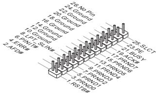
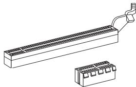
Parallel Port Header: JLPT1
This connector is used to connect an optional parallel port bracket. The parallel port is a standard printer port that supports Enhanced Parallel Port (EPP) and Extended Capabilities Parallel Port (ECP) mode.
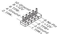
IEEE1394 Connector: J1394_1
This connector allows you to connect the IEEE1394 device via an optional IEEE1394 bracket.
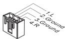
Clear CMOS Jumper: JBAT1
There is a CMOS RAM on board with an external battery power supply to preserve the system configuration data. With the CMOS RAM, the system can automatically boot OS every time it is turned on. If you want to clear the system configuration, use the button to clear data. Press the button to clear the data.


Keep Data

Clear Data
IMPORTANT
You can clear CMOS by shorting 2-3 pin while the system is off. Then return to 1-2 pin position. Avoid clearing the CMOS while the system is on; it will damage the mainboard.
Overclock FSB Switch: OC_SW1
You can overclock the FSB to increase the processor frequency by changing the switch. Follow the instructions below to set the FSB.

Default
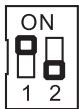
Increase 10% speed of CPU clock
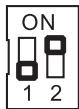
Increase 15% speed of CPU clock
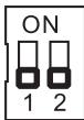
Increase 20% speed of CPU clock
IMPORTANT
- Make sure that you power off the system before setting the switch.
- When overlapping cause system instability or crash during boot, please set the switch to default setting.
APS LED Status Indicator:LED1
The APS (Active Phase Switching) LED indicates the current CPU power phase mode. Follow the instructions below to read.
LED1

| ON | The LED will light when CPU is in 3 phase power mode. |
| OFF | The LED will go off when CPU is in 1 phase power mode. |
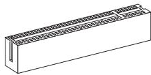
PCIE Slot
The PCIE slot supports the PCIE interface expansion card.
The PCIE 2.0 x16 slot
The PCIE x1 slot
PCI Slot
The PCI slot supports LAN card, SCSI card, USB card, and other add-on cards that comply with PCI specifications.
IMPORTANT
Make sure that you unplug the power supply first. Meanwhile, read the documentation for the expansion card to configure any necessary hardware or software settings for the expansion card, such as jumpers, switches or BIOS configuration.
PCI Interrupt Request Routing
When adding or removing expansion cards, make the IRQ, acronym of interrupt request line and pronounced I-R-Q, are hardware lines over which devices can send interrupt signals to the microprocessor. The PCI IRQ pins are typically connected to the PCI bus pins as follows:
| Order Slot | 1 | 2 | 3 | 4 |
| PCI 1 | INT A# | INT B# | INT C# | INT D# |
BIOS SETUP
Power on the computer and the system will start POST (Power On Self Test) process. When the message below appears on the screen, press key to enter Setup.
Press DEL to enter SETUP
If the message disappears before you respond and you still wish to enter Setup, restart the system by turning it OFF and On or pressing the RESET button. You may also restart the system by simultaneously pressing
Main Page
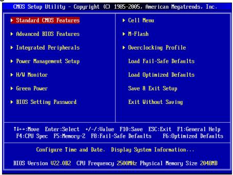
Standard CMOS Features
Use this menu for basic system configurations, such as time, date etc.
Advanced BIOS Features
Use this menu to setup the items of special enhanced features.
Integrated Peripherals
Use this menu to specify your settings for integrated peripherals.
Power Management Setup
Use this menu to specify your settings for power management.
H/W Monitor
This entry shows the status of your CPU, fan, warning for overall system status.
Green Power
Use this menu to specify the power phase.
BIOS Setting Password
Use this menu to set BIOS setting Password.
Cell Menu
Use this menu to specify your settings for frequency/voltage control.
M-Flash
Use this menu to read/ flash the BIOS from storage drive (FAT/ FAT32 format only).
Overclocking Profile
Use this menu to save/ load your settings to/ from CMOS for BIOS.
Load Fail-Safe Defaults
Use this menu to load the BIOS default values that are factory settings for system operations.
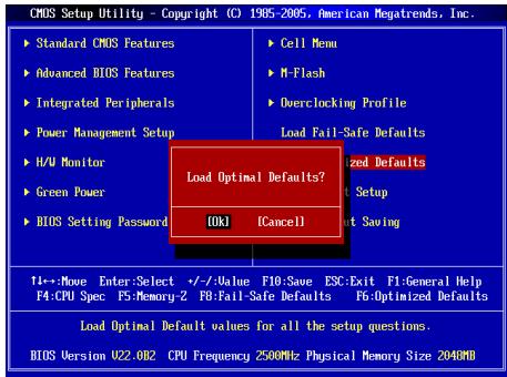
Load Optimized Defaults
Use this menu to load factory default settings into the BIOS for stable system performance operations.
Save & Exit Setup
Save changes to CMOS and exit setup.
Exit Without Saving
Abandon all changes and exit setup.
Cell Menu
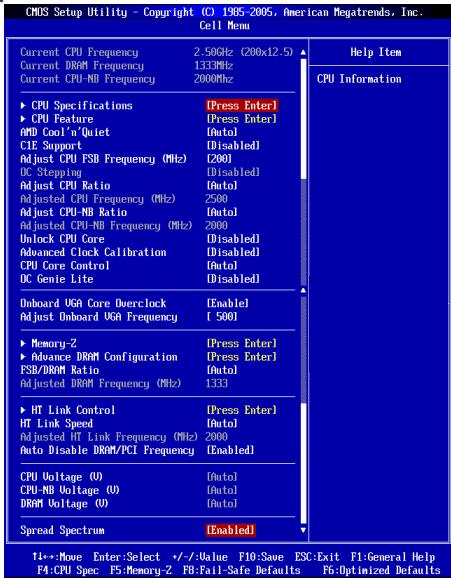
Current CPU / DRAM / CPU-NB Frequency
These items show the current clocks of CPU, Memory and CPU-NB speed. Read-only.
CPU Specifications
Press
CPU Technology Support
Press
CPU Feature
Press
AMD Cool'n'Quiet
The Cool'n'Quiet technology can effectively and dynamically lower CPU speed and power consumption.
C1E Support
To enable this item to red the CPU power consumption while idle. Not all poressors support Enhanced Halt tate (C1E).
SVM Support
This item allows you to enable/disable the AMD SVM (Secure Virtual Machine) Technology.
AMD Cool'n'Quiet
The Cool'n'Quiet technology can effectively and dynamically lower CPU speed and power consumption.
C1E Support
To enable this item to read the CPU power consumption while idle. Not all portessors support Enhanced Halt tate (C1E).
IMPORTANT
To ensure that Cool'n'Quiet function is activated and will be working properly, it is required to double confirm that:
- Run BIOS Setup, and select Cell Menu. Under Cell Menu, find AMD Cool'n'Quiet, and set this item to "Enabled".
- Enter Windows, and select [Start]->[Settings]->[Control Panel]->[Power Options]. Enter Power Options Properties tag, and select Minimal Power Management under Power schemes.
Adjust CPU FSB Frequency (MHz)
This item allows you to select the CPU Front Side Bus clock frequency (in MHz).
OC Stepping
This item will be enabled after you set the overclocking frequency in the "Adjust CPU FSB Frequency (MHz)". And the following items will appear. This items will help the system to overclock step by step after system booting up.
Start OC Stepping From (MHz)
This item is used to set the initial base clock. The system will boot with the initial base clock, and start to overclock from initial base clock to set base clock that you set in "Adjust CPU FSB Frequency (MHz)" step by step.
OC Step
This item is used to set how many steps for base colck overclocking.
OC Step Count Timer
This item is used to set the buffer time for every step.
Adjust CPU Ratio
This item is used to adjust CPU clock multiplier (ratio). It is available only when the processor supports this function.
Adjusted CPU Frequency (MHz)
It shows the adjusted CPU frequency. Read-only.
Adjust CPU-NB Ratio
This item is used to adjust CPU-NB ratio.
Adjusted CPU-NB Frequency (MHz)
It shows the adjusted CPU-NB frequency. Read-only.
Unlock CPU Core
This item allows you to unlock the additional cores, you could set it [Enabled] and then set Advanced Clock Calibration [Auto] in order to be able to activate the processor cores.
Advanced Clock Calibration
This item is for overclock. Setting to [Auto] allows you to set the CPU Ratio higher. It is available only when the processor supports this function.
CPU Core Control
This item is used to control number of CPU cores. When set to [Auto], the CPU will operate under the default number of cores. When set to [Manual], you will be able to enable/disable the specific CPU core.
Core 1/2/3/4
These items are used to enable/disable the core 1/2/3/4.
OC Genie Lite
Setting this item to [Enabled] allows the system to detect the maximum FSB clock and to overclock automatically. If overclocking fails to run, you can try the lower FSB clock for overclocking successfully.
Onboard VGA Core OverClock
This item allows you to enable/ disable the onboard VGA overclocking ability.
Adjust Onboard VGA Frequency
This item allows you to adjust the frequency of the onboard VGA core..
Auto OverClock Technology
Setting this item to [Max FSB] allows the system to detect the maximum FSB clock and to overclock automatically. If overclocking fails to run, you can try the lower FSB clock for overclocking successfully.
Memory-Z
Press
DIMM1~4 Memory SPD Information
Press
Advance DRAM Configuration
Press
DRAM Timing Mode
Select whether DRAM timing is controlled by the SPD (Serial Presence Detect) EEPROM on the DRAM module. Setting to [Auto] enables DRAM timings and the following "Advance DRAM Configuration" sub-menu to be determined by BIOS based on the configurations on the SPD. Selecting [Manual] allows users to configure the DRAM timings and the following related "Advance DRAM Configuration" sub-menu manually.
FSB/DRAM Ratio
This item allows you to select the ratio of FSB/ DRAM.
Adjusted DRAM Frequency (MHz)
It shows the adjusted Memory frequency. Read-only.
HT Link Control
Press
HT Incoming/Outgoing Link Width
These items allow you to set the Hyper-Transport Link width. Setting to [Auto], the system will detect the HT link width automatically.
HT Link Speed
This item allows you to set the Hyper-Transport Link speed. Setting to [Auto], the system will detect the HT link speed automatically.
Adjusted HT Link Frequency (MHz)
It shows the adjusted HT Link frequency. Read-only.
Auto Disable DRAM/PCI Frequency
When set to [Enabled], the system will remove (turn off) clocks from empty DRAM/PCI slots to minimize the electromagnetic interference (EMI).
CPU Voltage (V)/ CPU-NB Voltage (V)/ DRAM Voltage (V)
These items are used to adjust the voltage of CPU, Memory and chipset.
Spread Spectrum
When the mainboard's clock generator pulses, the extreme values (spikes) of the pulses create EMI (Electromagnetic Interference). The Spread Spectrum function reduces the EMI generated by modulating the pulses so that the spikes of the pulses are reduced to flatter curves. If you do not have any EMI problem, leave the setting at Disabled for optimal system stability and performance. But if you are plagued by EMI, set to Enabled for EMI reduction. Remember to disable Spread Spectrum if you are overclocking because even a slight jitter can introduce a temporary boost in clock speed which may just cause your overclocked processor to lock up.
IMPORTANT
- If you do not have any EMI problem, leave the setting at [Disabled] for optimal system stability and performance. But if you are plagued by EMI, select the value of Spread Spectrum for EMI reduction.
- The greater the Spread Spectrum value is, the greater the EMI is reduced, and the system will become less stable. For the most suitable Spread Spectrum value, please consult your local EMI regulation.
- Remember to disable Spread Spectrum if you are overclocking because even a slight jitter can introduce a temporary boost in clock speed which may just cause your overclocked processor to lock up.
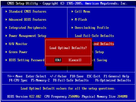
Load Optimized Defaults
You can load the default values provided by the mainboard manufacturer for the stable performance.
韓國兒
#
| CHS Setup |Hlity - Copyright (C) 1985-2006, American Megatrends, Inc. | |
| Standard CNS Features | Cell Menu |
| Advanced BIOS Features | M-Flash |
| Integrated Peripherals | Overclocking Profile |
| Power Management Setup | Load Fail-Safe Defaults |
| H/V Monitor | Load Optimized Defaults |
| Green Power | Save & Exit Setup |
| BIOS Setting Password | Exit Without Saving |
| →Move Enter:Select +/-Value F10;Save ESC:Exit FI-General Help F4:CPU Spec F5:Memory-2 F0:Fail-Safe Defaults F6:Optimized Defaults | |
| Configure Time and Date. Display System Information... BIOS Version 022.002 CPU Frequency 2500MHz Physical Memory Size 2040MB | |
Standard CMOS Features(亚声CMOS趋)
iEe 1
Integrated Peripherals(通传则)
i
Adjust CPU Ratio(CPU bit to 0)
Adjusted CPU Frequency(主请回CPU所加) (MHz)
i
Adjust CPU-NB Ratio(CPU-NB bit to 0)
i
Adjusted CPU-NB Frequency(正置回CPU-NB串行) (MHz)
此哈默是CPU-NB主和数来五时自。
CPU Core Control(CPU Kjaer)
Adjusted HT Link Frequency(主詠詞HT彌克專所) (MHz)
i
Auto Disable DRAM/PCI Frequency(DRAM/PCI 即可)
Press DEL to enter SETUP
Advanced BIOS Features
Integrated Peripherals
BIOS Setting Password
Overclocking Profile
Current CPU / DRAM / CPU-NB Frequency
CPU Technology Support
Adjust CPU FSB Frequency (MHz)
Start OC Stepping From (MHz)
Adjusted CPU Frequency (MHz)
Adjusted CPU-NB Frequency (MHz)
Advanced Clock Calibration
Adjust Onboard VGA Frequency
Adjusted DRAM Frequency (MHz)
HT Incoming/Outgoing Link Width
Adjusted HT Link Frequency (MHz)
KOMHOENTbI CNCTeMHoNIIaTbI
XAPAKTEPNUCTIKN
Ipoceccopb
■ПeroceccpoIy AMD®PhenomII/ Phenom I/ Althon II/ Althon Sempron B KOHCTPyKITBE AM 3.
(IINyHcNcMOHOBINHOpMaUNO CPU,ncetnte canT
http://www.msi.com/index.php?func=cpuform2)
HyperTransport
- ПобдевжkaTeXнологин Hyper Transport(HT) 3.0
Yuncet
CebepnbMoCT:AMD880G
IOxHbIMoCT:AMD SB710
NamrTb
DDR3 800/1066/1333/1600*(OC)SDRAM(16GB Max)
(3aДоержндухканальогрекIMa
Паоллгпьнлсинформачио nо доержнбамьmoydnyaxnosite
caiHT: http://www.msi.com/index.php?func=testreport)
LAN
- Podéprkka LAN 10/100/1000 Fast Ethernet на чиncete Realtek® RTL8111E
Aydno
INTerpnoBaHHbY YInCet Realtek ALC892
8-KaHaJIbHOe aydno C rN6KIM npeHa3HaueHnem pa3bEmOB
COBmectnmoctb co cneuФkauei Azalia 1.0
IDE
1 nopT IDE ha yunncete AMD® SB710
Подержka peхимов pa60Ты Ultra DMA 33/66/100, PIO& Bus Master
SATA
6 nopTOB SATA 3Γ6/c Ha unncete AMD® SB710 (SATA1~6)
2 noptra SATA 6Γ6/c ha qunncete Marvell® SE9128 (SATA7~8)
ΦJONnn
1ФJIOONnnoT
Iopdeprka1FDDc360KB,720KB,1.2MB,1.44MBu2.88MB
KOHHeKTopbI
3aDne nanei
- 1 onTnueckn S/PDIF-Out
- 1 PS/2 nopT MbIuN/ KnabnAtypbl
- 1 nopT VGA
- 1 nopT DVI-D
- 1 nopT HDMI
- 1 nopT IEEE 1394
- 4 nopTa USB 2.0
- 2 nopTa USB 3.0
- 1 pa3bem LAN
- 63ByKOBbIX pa3beMOB Cn6KIM npeHa3NaeHHeM
Pa3bEmbl, yTcaHOBHeHHbIe Ha nIaTe
- 1 pa3bem napaannenbHoro nopTa
- 3 pa3bema USB 2.0
-1pa3bemIEEE1394 - 1 pa3bem nocleIOBaTeIbHoro npota
- 1 pa3beM SPDIF-Out
- 1 pa3bem dЯ NOdklouheny aydno Ha nepedne nahenn
- 1 pa3bem DaTUnka OTKpbBaHnK Kopnyca
- 1 pa3bem CD-In
- 1 pa3bem TPM
- 1 nepekniouataeNb
CnotbI
1 cnot PCIE x16
2cnotaPCIEx1
1 cnot PCI, noDepkka nHTeppeca PCI uHbC nTnTaHmE 3.3V/5V
ΦopM ΦakTop
Micro-ATX (24.4cm X 24.4 cm)
KpennneHne
8OTBepCTnIaI KpeJIeHna
(POMOJIb B PnO6pBTeHnn DOnoPnHIneTneHbIX AKeCCeCyapOB N OINcKe HOMepa
N3dEJIIM NOKHO NaIITNo aDpecy
http://www.msi.com/index.php)
3aHnaH naHbI npedocabnre cneyuOuNcpepaBembl:
YCTAHOBKA OBOPUIOBAHIN
YctahOBka npoecccopa n BENTINrTopa dAAM3
Bou n36eJahnne neperpeba npri pa6othe o6raatenaHo yCTaHObITE BENTINIATOP npOeCCopa. OndHOBPemEHNO, YTOb6y bEYInuHTb TENOpACCenBaHne, yBeDITcB B TOM. YTO hAHeCen CnO TEN NpONpOBODJaueN NaCTb Hn pOeCCope npi yCTaHOBKe BEHTNIATOPa.
BudnpoueesscopaAM3cBneuHne CTOPnbl.
He 3a6ydbTe HaneCTe TENnonpOBoRDyUO nacty dna 60nee 3ΦΦeKTHBHO TennopacceBAHIN.

3oIota cTpeKa
Cnedyte DaHbHM yKa3aHmD nI npabInbHnoy uYctAHOBKn. HennpabInbHaJy uYctAHOBKn pnpBdet K noBpeXdHIO npOeCCOPN cNCTeMHOn nPbTa.
- PodnHmMTe B BEptrKaIbHoNE noNoJoxHepe pbuHaxok, HAOxDriyamC60kyBa3bEma.
- 06pntte BnImaHne Ha 3oIOnTuO CTpeNky (gold arrow) HA CPU. OHa DOnJXHa BbIt paCnONoxHe TaK, KaK POKa3aHO Ha pncyHke. CPU MoKHO BCTaBtB ToJIbKO npr erO npabINbHOBOpNEHTaUHN.
- Pn npabmbnoyctahobke CPU ero kOHTaktbI NOHOCbTO BOYdUT B pa3bEm, n IHe 6yDet BvNDHO. NOMHITE, YTO IIObIe npImeHHeNc Ntbl Pn yCTAHOBKe CPU MOKET Bb3BaTc cepb3hBe NoBpeKdHnue CIsTeHMn POaTbI.
4.Akkyapatrno pnpKMMTE CPU Kpa3bemyu andyctne tpbHaxok. Pocckoby CPU npn onyckanHHpHuKAA MOKET nepeMeCTTbC8, octopOKHO npKMMTE CPUNaIbAMN BcHTPE TAK, YTO6bOn OH npabInbHo H nIOHocBtO 3aФнКcPobAONCB pa3bEe. - Pâmečte těběnnítrop há yzéne kpenětněHQ. Bhučáne zaučěnítě oĐÍN erO ekpá.
- 3aTeM Haxkmtte Ha dpyroi Kpaai, TcboBly yctahOBnTb padatop Ha yen KnpenneHn. HauNtde pnyar fikncsauin noDnHMtte ero.
- 3aФнксуп Te paДиаTOp ДаьнeншIM NOBOPOTm pbHara.
- IopKIOHcTe Ka6eBbENTINaTOpa Cpu K COOTBeCTByIOUcEMy pa3bEmy CNCTEMMOI nptbl.
BHIMAHVE
Pazbem nopepkjBaAeT noeknlochHne XeCTKHX DNCKOB IDE, ONTNUecknx DNCKOB nDpyrIX IDE yctpOCTB.

BHIMAHHE
Pnno ndknoeHH mDyX yctpoiBCT hA OHm Kabe, cnedyet yctahOBntb yctpoiBa pekim master / slave nocpeCTbOM yctahOBKn pepeMbYek. 3a nHTCPTKUJIAMM OBPATNTteB k DOKUMEHTaUNI HZOTOBHTEN YCTPOCTBA.
Pa3bem Serial ATA: SATA1 ~ 8
Pa3bEm Serial ATA - 30 ByCOKOOPCOTNOH nort HENTPefCa Serial ATA. 3TOT pa3bEm p03BONJET NOKNIQHTB ToNko ODO yCTPOICTBO Serial ATA.
BHIMAHHE
IV36eBae pe3kXn IaHbO B Kaebna Serial ATA. B npotnbHM cnyae MoryT BOBHKNHTy notepn dAnhIX np nepeDaue.
Pazbem nitaHnBEHTnIaTOpOB: CPUFAN, SYSFAN1, SYSFAN2
PazbEmbl NtHnAaBbBHTNlTApOB NOIeDPKXBAAOT BENTHJLTopbC nITNAHE +12 B. PnINoDKIIOUeHN HeOxODIMo NOMHNT, YKTcKbHn NpOBd ONDkHnOaETcR K UINHe +12 B,a CEPbH-b K 3EMe GND.EcN CmCTEHMa NtNaTe cOePKHt MInKPOCXemy AnnapathrO MOHNTOPHRA, HeOxODIMo IcNOrb3OBatb CneuHaNbHbe BENTHJLTopbC daTcHKom CKOpOCTn DnpeaIN3aUMfYHKuYNpABNeHNB EHTNlTApOM.
Pa3bem S/PDIF-Out:JSP1
3ToT pAsbem nCOnIb3yETc4 dnn PnOKnIOUeHn HInTePcEma S/PDIF (Sony & Philips Digital Interconnect Format) dnn nepeaun 3Byka B UΦpOBOM φopMaTe.
Pazem CD-In: JCD1
3T0t pabaem npedna3auehen dnoNoknoueHH NOONHHTbHOro aydno Ka6eBn.
Pazbem nIpoKIOUeHnnepeDne nnHeJ:JFP1,JFP2
3TN pa3bEmbl 6oceNeBBAOT NODKIOHueHne KHOJOK INHMkATOPOB nepeDnei naHEn. JFP1 cooTBeTCTByeT cneuФнkauzin Intel® Front Panel I/O Connectivity Design Guide.
Pazbem nocjeboTaBHO npTa: JCOM1
Main Page (OchOBHoe MeHIO)

Standard CMOS Features (CTaHdapTbIe yHKm CMOS)
3TO MEHOI PO3BOJRET yCTAOHOBtB OCHOBHbE napAMETpBI KOHNrpyaunu CImCTEmbl (dAty, BPMeR, n T.D.).
Integrated Peripherals (BCTpoehhble nepupepnhbye yctpoicta)
3ToMeHIOIcnpbIaByeTcAJnHaCTpoIKnnapaMetPOB BCTPOeHNbX nepiFepeRINbIX yuctoCTB.
Power Management Setup (Hactpoika ynpablenia nitaHnem)
3TO MEHIO N03BOJAE T3aTaB npaMeTpbl ynpaBneHn NITAHmCnCTeMbI.
H/W Monitor (MoHTop annapaTHOy actn)
3TOT nyHKT OTO6paKaAe COCTOaHne annapatnoh Yactn PIK.
Green Power
3To MeHIO nCNoB3yeTcI dIg Ha3HaueHnpeXmAmNTaHn.
Overclocking Profile
IcnoIb3yETcIaXpaHEnI/ 3arpy3kn npametpoB I/3 CMOS BIOS.
Load Fail-Safe Defaults
3To MEHIO NcNOB3yETcN 3aqrpy3n 3aHcNEHBIOS,yCTaHOBENbIX npno3BtIeTmE nTcStbInbHOB paBoTbI cNtCEMb.
Load Optimized Defaults (YctaHOBITb ONTMMAbHbIe HAcTpOKn)
3To MeHIO ICNOpIbEyctar DcY JCTAHOBK INACTPOEK INAOBOTENIEL DnA ONTUMALHOINPOINBODENTBHOCTN CHTEMHNO PnATb.
Save & Exit Setup (BbIXoD c coXpaHHeHem HactpoeK)
3aIINcB n3MeHEnB CMOs u BbIXoN u pexKmHaNCTpoKn.
Exit Without Saving (BbIXoD 6e3 coxpaHeneH)
OTMeHa BCEx N3MeHeHn I BbIXoN I3 peKIma NaCTpoKn.
Cell Menu

Current CPU / DRAM / CPU-NB Frequency
3TN NyHKtI NOkəbaIbAOT KeTyUO YactOT CPU, cKopocTb namrTI nCPU-NB. TofkoDn4 TcHnA.
CPU Specifications
JahMkme
CPU Technology Support
HakmmtE
CPU Feature
Haxmnte
AMD Cool'n'Quiet
TexHONOR NoCuiKieN QoB3OAneT 3aEKeKTHBNO dHAMMueCKN M3MEHnTb 卷CTO CPU nHepronotpe6JIneH NcIeTeMbI.
C1E Support
BKN0UHTE 3OT NTKJN DnA CHKENHIE 3HEPONOTpe6HENI CPU, KORA OH pKaTaETA. He B Nce pOeCoppb NoDaePcKBaIOHT Enhanced Halt state (C1E).
SVM Support
3TOT nyHKT no3B0JAEET BKNIOATb/BykIOaHTb TExHOONIO AMD SVM (Secure Virtual Machine).
AMD Cool'n'Quiet
TexHONORa Cool'Quiet no3BOJare 3ΦΦeTKBHO DnHAMMueckn 13MeHNrTaCTO CPU n 3heponrTOpe6NEHeN CHTeMbI.
C1E Support
BknOHTe 3OTy NHTI kHnENHEA HEPRONOTpe6JIHnC PCU, KOgDA OH He paOaTeTae. He BcNpoueccBoI noDedePbXbaOT Enhorted Halte state (C1E).
BHIMAHVE
Ycbb y6bdntb a TOM, YTO texhONrHg Coof'n'Quiet BkIOHena n paB0TaET npabInbHo, Heo6xoHmo:
3aHn B nporpammy BIOS Setup, n bivbpatr Cell Menu. Hauhnte AMD Cool'nQuiet noct Cell Menu, u yctanohrote ero a Enabled"Enabled".
* B Windows vybepurte [Start]->[Settings]->[Control Panel]->[Power Options]. Bovdune B Power Options Properties, vybepurte Minimal Power Management noq Power schemes.
Adjust CPU FSB Frequency (MHz)
TOT nyHKT nO3BONaET peryIINPOBaTaY FSB npouecoppa (B MfU).
OC Stepping
3TOT npHKT BKNIOHEN NOCNE ytaHOBNI cAOTbIpaROna B "Adjust CPU FSB Frequcncy (MHz)".NcIeLIOUJIe NYKtBI NpOBIIaIOCTc. OH nO3BOJrE tOcUeCTBnTb paROn 84 3a 7aAROM NoCNE 3aRyP3cI CStEMb.
Start OC Stepping From (MHz)
3TOT nyHTN 03BONHT yCTAHOBINT hauanbHoe 3HAeHHe TAKTOBOI YACTOTBI (base clock). CNTEMTA 3ARpy3TcR C hauanbHM 3HAeHEM TAKTOBOI YACTOTBI (base clock), a NOTOM HauHTEN p430rHbT CTHEMY C hauanbHoro 3HAeHHe HAJ 3a 3a warom yCTAHOBnEHBM B "Adjust CPU FSB Frequency (MHz)".
OC Step
3TOT nyHKT INCNONb3yeTcRA dIy yCTAHOBK Iwara pa3ROHA TAKTOB OY cAToTbI (base colch).
OC Step Count Timer
TOT nyHKT nCnObl3yETcA dny yCTaHOBKn BpeMeHn 3aepKk KaJdoI O waI.
Adjust CPU Ratio
3TOT nyHKT nCnOblayetc dA pernyIPOBMK MHOXKITNE npoecccp. OH doCTynHToNkoTOrda, KOrDa npoecocc NoadpeKbMaert 3y fYhKNUIO.
Adjusted CPU Frequency (MHz)
3TOT nyHKT noka3bIbaeT kcyuio qactOtu CPU. TOnbKO dnyteHna.
Adjust CPU-NB Ratio
ETOTnyHKNTNcONb3ayetcndperpynnpOBKuacToTBCPU-NB.
Adjusted CPU-NB Frequency (MHz)
3TOT nyHKT noka3bIbaET TeKuIyU yactOty CPU-NB.ToIbKO dnyTeHnA.
Unlock CPU Core
3TOT NHYKT NOBONET PA36NOKIOPOBATb DONONHITENbIe YINCETbl, BAM MOXHO yCTAHOBNTb EoB [Enabled] n NOT yCTAHOBNT Advanced Clock Calibration B [Auto], YTOsb IMEMb BO3MOXHOCTb AKTNIBIOPOBATb npOecOPBHeYINCETbl.
Advanced Clock Calibration
3TOT NYHK TcNOpb3yETcI DnA pa3rOHa. YcTaHOBka B [Auto] no3BONReY cTaHOBt bactOty CPU bIwe. OH dcTyIeN toIbKO torDa, kOrda pIoceccpNoIaeKbIAEET 3Tu fyHKnUIO.
CPU Core Control
3TOT NYHKT NcOINb3yETcA DnI KOHTpONIOBAAHn HOMepa npoecccopHOro YNCHcTa. Pnp yctahOBBe B [Auto], CPU paobotaet noD homepom YNCHcTeB NO ymOLAHNo. Pnp yctahOBBe B [Manual], BAM MOxHO BKNIOATb/BkIKIOuATb ONpeDENEHHy ChNcET CPU.
Core 1/2/3/4
3nnyHKtbI NCN0b3yIOCTa IINB KIIIOUeHb/BBKIIIOUeHMy UINcTeOB 1/2/3/4.
OC Genie Lite
YCTAHOBKA 3T0R nyHKTBA [Enabled] no3BONJET NO3BOJETC NCTE ME ONPDEENTB MAKCMMAbHyIO HACTOTy FSB n p3aRHO INABOMTAYNECKn. Ecm p3aRHO He ydANC, BAM MOXHO YMEHbUHTy TaKTOBYO cHACTOTy FSB dNn p4aRHO yduHNO.
Onboard VGA Core OverClock
ETOTnyHKNT03BONJETBKKIOUHTb/ BbIKIOUHTb pa3roH VGAHa nate.
Adjust Onboard VGA Frequency
3TOT nyHKT no3BONJeT perynipobaTb qactoTbYHnCeTa VGA ha nnaTe.
Auto OverClock Technology
UctahOBaB B [Max FSB] no3BONJeR BIOS ATOmatuYeCKN OponeDenHb MaksmAbHyIO qactOry FSB n pa30rHaTb cStcEmy. Ecnn pa30rh He ydanCn, Bbl MokTebe NoPpOboBaTb NoHN3Mb Chactory FSB dny aYdHoro pa3oHa.
Memory-Z
HaxmTe
DIMM1~4 Memory SPD Information
HakmniE
Advance DRAM Configuration
HaxmTe
DRAM Timing Mode
OnpeDene 6ydtn BpeMeHbIe napameTpbl DRAM KOHTpOIOBATcB daHHIM n3 SPD (Serial Presence Detect) EEPROM ha moJyDE DRAM. Pnp bbl6ope 3haeHnra [Auto], BpeMeHbIe napameTpbl DRAM, 8KnUo7a yNtKbT MeHIO, nepeYusCenHbIe Hnxke, yctaHabIbMaOTcB BIOS b COOTBeCTbn C daHHIM n3 SPD. Pnp yctahOBKe 3haeHnra [Manual], 3OT nyHKT no3BONBJE BpyHuO peYunipobatBpeMeHbIe napameTpbl DRAM DOCTynHbIe B 3OT
MEHIO.
FSB/DRAM Ratio
3TOTyHKNTo3BONHTeperyIINPOBATb Ko3ΦΦnIeHT MEXdy NaCTOTAMN FSB n naTMBy.
Adjusted DRAM Frequency (MHz)
3TOT nyHKT nOKa3bIbaet 3NaueHne yactoTBi naMaTn. TOnbKO dnyTeHnA.
HT Link Control
Haxmnte
HT Incoming/Outgoing Link Width
3TOT NYKTH ONEPENIET WIPINHY BXOJARIE/MCXOJAISEUHNHIT. HTpynycbAOKBE B [Auto].CTCITEMAbotOMaTHueCKN ONEPENIET WIPINHYWNIHHT.
HT Link Speed
3TOT nyHKT no3oBONeY yCTaHOBNb cKOpOcTB nepeDauNo 0uHe HyperTransport. Ptyn yCTaHOBKe B [Auto], CnCTema aBtOMaTHueckn onpeDeJeRt cKOpOcTB uHNb HT.
Adjusted HT Link Frequency (MHz)
3TOT nyHKT nOKa3bIbAe TEkyu yactOy uINhbl HT. TOnbKO dnyTeHnA.
Auto Disable DRAM/PCI Frequency
Pn yctaHOBKe 3naueHInn [Enabled], CnCTeMa OTKnIOHT NHeCNPOB3yEmbIe pa3BeMn pAmrTn nPCI, TTO npNBeTeK cnHexeHIno YOBoHn 3NeKTPomarHnTHbIX nomex (EMI).
CPU Voltage (V)/ CPU-NB Voltage (V)/ DRAM Voltage (V)
3TOT nyHKT no3BOJAEr perynipoBaTB HanpJKeHne CPU, naMaTn uYnceta.
Spread Spectrum
TAK KAK TAKTOBBI reHepatop CNTeMHOI PnATbI MMNyIbCHbI, To erO pa6oTa BblBaet 3eKtPOMarHnTHbIe nomexi - EMI (Electromagnetic Interference). FHykUaSPread Spcrtum ChnKaET 3tn NOMEXi, rHepepyr crzAKeHNbIe MMNyIbCSbI. EcIn y Bac HET np6bnem CnOMexAmn, OCTabTe 3hauChenE [Disabled] (3anpeJeHo) DnI pyuSeI CTabINbHocNI n pOn3BOdITeHbNcH. OndAko, ECIn y Bac BO3NHKAOT 3NeKtPOMARHnTHbIe NOMxI, pAsPeWHe NcONb3BOBaHne 3Tof FHyKnUm, YCTaHOBNB [Enable] (pa3peSeHo). He 3a6yIbTe 3anpETmIB NCNb3BOBaHne FHyKnUm Spread Spcrtum, ecIn bY (pa3OrHnTe) CNTeMHyo nAty. 3To Heo6XoHMo, TAK KAK DaJke HeobLshO nDpe6Be rCnHAnOB TAKTOBOr REheparato MOpKET nPiBeCTN OK tAky (pa3OrHaHHOrO) nPoceecoppa.
BHIMAHHE
- Ecnny y Bac Het npobnem c nomexamu, octabte 3auehene [Disabled] (aanpeueho) dny nuyuwe ctaunbnoctn u pno3bointenbnoctn. Ondako, ecnny y bac Bo3Nkaot 3neKpomarHtBHeI nomexn, Bb6epnte Spread Spectrum dny uxymehbuehna.
*Emb05ne3hauhenSpread Spectrum,temHIXebyet ypobenb 3nKtpomarHHTbIX nomex,Ho cStema cTahet MeHee cTabinbNoi.Дль bIbopa nOxOxJyero 3hauhenya Spread Spectrum,CbpeTbeCo h3auhenHHM
ypoBHe3NeKtpomarHHTbIX NOMEx,yCTaHOBnEHHbIX 3aKOHOdaTeNbCTBOM.
* He 3a6yblte 3anp9tntb IcnpIb3oBaHne FynKcnn Spread Spectrum, ecn Bby (pa3roHnEeT) CNTeMThy nIaTy. 3To He6xOJIMMo, TAK KaK DaJke He6onlsuOn dpe6e3r CInHaNoR TaKTOBOr reHepatopA MoKeT npBBeCTN K OTKa3y (pa3orHaHHoro) npOceccopa.
YcTaHOBka 3NaueHnI NO yMOJuaHIO
IaCTa6bHbONpAOBtOblCNTBMeBLbMOXeTEZ4BPHTbHCTPOBNI BOSNo UMOJTHN,YCTAOBnENHBEIpNO3BQDITENEM CNTTEMHOIIPTbL.
简体中文
简介
Press DEL to enter SETUP
CPU Specifications (CPU 属性)
Start OC Stepping From (MHz)
Adjusted HT Link Frequency (MHz) (调整后的HT连接频率)
此项显示调整后的HT连接频率。只读。
Press DEL to enter SETUP
(按DEL键進入設定)
CPU Specifications (CPU 規格)
CPU Feature (CPU 功能)
按下
AMD Cool'n'Quiet
Adjust CPU FSB Frequency (MHz) (調整 CPU 外頻)
Start OC Stepping From (MHz)
Adjusted CPU Frequency (MHz) (調整後CPU頻率)
本項顯示調整後CPU的頻率。唯讀。
Unlock CPU Core (CPU開核)
Press DEL to enter SETUP
(を押て設定画面をYPじ出す)
Integrated Peripherals (内藏機能の設定)
CPU Technology Support (CPUtekNoJ-saPob-1)
CPU Feature (CPUの機能)
C1E Support (C1E-扑一卜)