
G52-77151X1 - Laptop MSI - Free user manual and instructions
Find the device manual for free G52-77151X1 MSI in PDF.
User questions about G52-77151X1 MSI
0 question about this device. Answer the ones you know or ask your own.
Ask a new question about this device
Download the instructions for your Laptop in PDF format for free! Find your manual G52-77151X1 - MSI and take your electronic device back in hand. On this page are published all the documents necessary for the use of your device. G52-77151X1 by MSI.
USER MANUAL G52-77151X1 MSI
FCC-B RADIO FREQUENCY INTERFERENCE STATEMENT
This equipment has been tested and found to comply with the limits for a class B digital device, pursuant to part 15 of the FCC rules. These limits are designed
to provide reasonable protection against harmful interference in a residential installation. This equipment generates, uses and can


N1996
radiate radio frequency energy and, if not installed and used in accordance with the instruction manual, may cause harmful interference to radio communications. However, there is no guarantee that interference will occur in a particular installation. If this equipment does cause harmful interference to radio or television reception, which can be determined by turning the equipment off and on, the user is encouraged to try to correct the interference by one or more of the measures listed below.
Reorient or relocate the receiving antenna.
Increase the separation between the equipment and receiver.
Connect the equipment into an outlet on a circuit different from that to which the receiver is connected.
Consult the dealer or an experienced radio/ television technician for help.
Notice 1
The changes or modifications not expressly approved by the party responsible for compliance could void the user's authority to operate the equipment.
Notice 2
Shielded interface cables and A.C. power cord, if any, must be used in order to comply with the emission limits.
VOIR LA NOTICE D'INSTALLATION AVANT DE RACCORDER AU RESEAU.

Micro-Star International MS-7715
This device complies with Part 15 of the FCC Rules. Operation is subject to the following two conditions:
(1) this device may not cause harmful interference, and
(2) this device must accept any interference received, including interference that may cause undesired operation.
PART NUMBER
G52-77151X1
COPYRIGHT NOTICE
The material in this document is the intellectual property of MICRO-STAR INTERNATIONAL. We take every care in the preparation of this document, but no guarantee is given as to the correctness of its contents. Our products are under continual improvement and we reserve the right to make changes without notice.
TRADEMARKS
All trademarks are the properties of their respective owners.
MSI is registered trademark of Micro-Star Int'l Co., Ltd.
NVIDIA® is registered trademark of NVIDIA Corporation.
ATI® is registered trademark of ATI Technologies, Inc.
AMD is registered trademarks of AMD Corporation.
Intel is registered trademarks of Intel Corporation.
Windows® is registered trademarks of Microsoft Corporation.
AMI is registered trademark of American Megatrends, Inc.
Award® is a registered trademark of Phoenix Technologies Ltd.
Sound Blaster® is registered trademark of Creative Technology Ltd.
Realtek® is registered trademark of Realtek Semiconductor Corporation.
■ JMicron® is registered trademark of JMicron Technology Corporation.
Netware is a registered trademark of Novell, Inc.
REVISION HISTORY
| Revision | Revision History | Date |
| V1.0 | First release | October 2010 |
SAFETY INSTRUCTIONS
Always read the safety instructions carefully.
- Keep this User Manual for future reference.
- Keep this equipment away from humidity.
Lay this equipment on a reliable flat surface before setting it up.
- The openings on the enclosure are for air convection hence protects the equipment from overheating. Do not cover the openings.
- Make sure the voltage of the power source is at 110/220V before connecting.
- Place the power cord such a way that people can not step on it. Do not place anything over the power cord.
Always Unplug the Power Cord before inserting any add-on card or module.
All cautions and warnings on the equipment should be noted.
- Never pour any liquid into the opening that can cause damage or cause electrical shock.
If any of the following situations arises, get the equipment checked by service personnel:
The power cord or plug is damaged.
Liquid has penetrated into the equipment.
The equipment has been exposed to moisture.
The equipment does not work well or you can not get it work according to User Manual.
The equipment has been dropped and damaged.
The equipment has obvious sign of breakage.
DO NOT LEAVE THIS EQUIPMENT IN AN ENVIRONMENT UNCONDITIONED, STORAGE TEMPERATURE ABOVE 60^ (140^) , IT MAY DAMAGE THE EQUIPMENT.
CAUTION
Danger of explosion if battery is incorrectly replaced.
警告使用者
For better environmental protection, waste batteries should be collected separately for recycling or special disposal.
ENGLISH
To protect the global environment and as an environmentalist, MSI must remind you that...
Under the European Union ("EU") Directive on Waste Electrical and Electronic Equipment, Directive 2002/96/EC, which takes effect on August 13, 2005, products of "electrical and electronic equipment"

cannot be discarded as municipal wastes anymore, and manufacturers of covered electronic equipment will be obligated to take back such products at the end of their useful life. MSI will comply with the product take back requirements at the end of life of MSI-branded products that are sold into the EU. You can return these products to local collection points.
DEUTSCH
Thank you for choosing the 870-SG45/ 870-C43 series (MS-7715 v1.x) ATX mainboard. The 870-SG45/ 870-C43 series is design based on AMD® 770 & SB710 chipset for optimal system efficiency. Designed to fit the advanced AMD® AM3 processor, the 870-SG45/ 870-C43 series deliver a high performance and professional desktop platform solution.
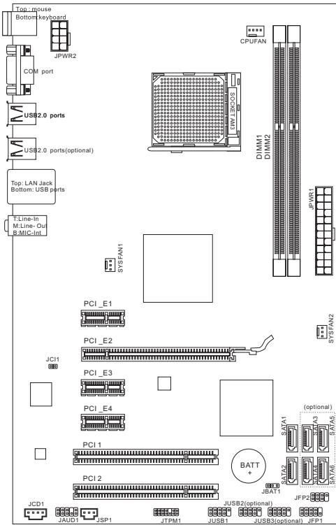
Layout
SPECIFICATIONS
Processor Support
- AMD® PhenomII/ Phenom/ Althon II/ Althon/ Sempron processors in AM3 package.
(For the latest information about CPU, please visit
http://www.msi.com/index.php?func=cpuform2)
HyperTransport
Supports Hyper Transport(HT) 3.0 Technology
Chipset
North Bridge: AMD® 770 chipset
South Bridge: AMD® SB710 chipset
Memory Support
DDR3 800/1066/1333/1600*(OC)SDRAM(8GB Max)
Supports Dual-Channel mode) (For more information on compatible components, please visit http://www.msi.com/index.php?func testreport)
LAN
Supports LAN 10/100/1000 Fast Ethernet by Realtek® RTL8111E (for 870-SG45)
Supports LAN 10/100 Fast Ethernet by Realtek® RTL8105E (for 870-C43)
Audio
Chip integrated by Realtek® ALC887
Flexible 7.1-channel audio with jack sensing
Compliant with Azalia 1.0 Spec
SATA
6 SATA 3Gb/s ports by AMD® SB710 (for 870-C43)
2 SATA 3Gb/s ports by AMD® SB710 (for 870-SG45)
Connectors
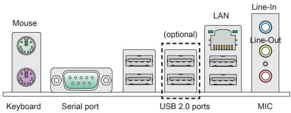
Back panel
-1PS/2 mouse port
- 1 PS/2 keyboard port
- 1 Serial port
- 4 USB 2.0 Ports (for 870-SG45)
- 6 USB 2.0 Ports (for 870-C43)
- 1 LAN jack
- 3 flexible audio jacks
On-Board Connectors
- 1 USB 2.0 connector (for 870-SG45)
- 3 USB 2.0 connectors (for 870-C43)
- 1 SPDIF-Out connector
- 1 Front Panel Audio connector
- 1 Chassis Intrusion connector
- 1 CD-In connector
- 1 TPM connector
Slots
1 PCIE x16 slot
3 PCIE x1 slots
2 PCI slots, support 3.3V/5V PCI bus Interface
Form Factor
ATX (19.0cm X 30.5 cm)
Mounting
6 mounting holes
(If you need to purchase accessories and request the part numbers, you could search the product web page and find details on our web address below http://www.msi.com/index.php)
SCREW HOLES
When you install the mainboard, you have to place the mainboard into the chassis in the correct direction. The locations of screws holes on the mainboard are shown as below.
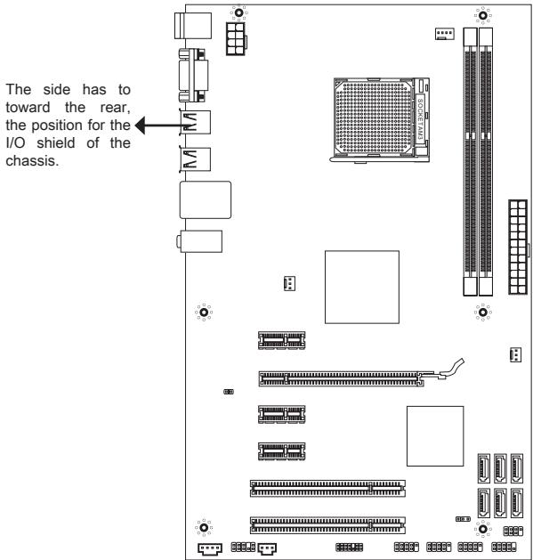
Refer above picture to install standoffs in the appropriate locations on chassis and then screw through the mainboard screw holes into the standoffs.
IMPORTANT
- To prevent damage to the mainboard, any contact between the mainboard circuit and chassis or unnecessary standoffs mounted on the chassis is prohibited.
- Please make sure there is no metal components placed on the mainboard or within the chassis that may cause short circuit of the mainboard.
REAR PANEL
The rear panel provides the following connectors:
HARDWARE SETUP
CPU & cooler Installation for AM3
When you are installing the CPU, make sure the CPU has a cooler attached on the top to prevent overheating. Meanwhile, do not forget to apply some thermal paste on CPU before installing the heat sink/cooler fan for better heat dispersion.
The surface of AM3 CPU.
Remember to apply some thermal paste on it for better heat dispersion.
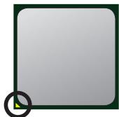
Gold arrow
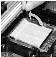
Follow the steps below to install the CPU & cooler correctly. Wrong installation will cause the damage of your CPU & mainboard.
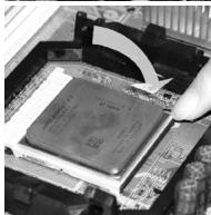
- Pull the lever sideways away from the socket. Make sure to raise the lever up to a 90-degree angle.
- Look for the gold arrow of the CPU. The gold arrow should point as shown in the picture. The CPU can only fit in the correct orientation.
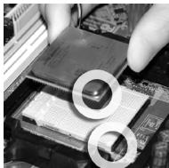
- If the CPU is correctly installed, the pins should be completely embedded into the socket and can not be seen. Please note that any violation of the correct installation procedures may cause permanent damages to your mainboard.
- Press the CPU down firmly into the socket and close the lever. As the CPU is likely to move while the lever is being closed, always close the lever with your fingers pressing tightly on top of the CPU to make sure the CPU is properly and completely embedded into the socket.
- Position the cooling set onto the retention mechanism. Hook one end of the clip to hook first.
- Then press down the other end of the clip to fasten the cooling set on the top of the retention mechanism. Locate the Fix Lever and lift up it.
- Fasten down the lever.
- Attach the CPU Fan cable to the CPU fan connector on the mainboard.
IMPORTANT
- Mainboard photos shown in this section are for demonstration of the cooler installation for Socket AM3 CPUs only. The appearance of your mainboard may vary depending on the model you purchase.
- While disconnecting the Safety Hook from the fixed bolt, it is necessary to keep an eye on your fingers, because once the Safety Hook is disconnected from the fixed bolt, the fixed lever will spring back instantly.
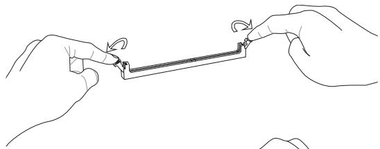
Installing Memory Modules
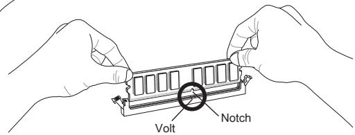
- The memory module has only one notch on the center and will only fit in the right orientation.
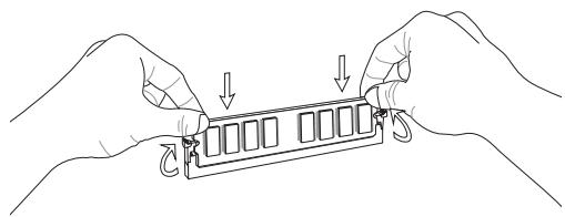
- Insert the memory module vertically into the DIMM slot. Then push it in until the golden finger on the memory module is deeply inserted in the DIMM slot. You can barely see the golden finger if the memory module is properly inserted in the DIMM slot.
- Manually check if the memory module has been locked in place by the DIMM slot clips at the sides.
IMPORTANT
- In Dual-Channel mode, make sure that you install memory modules of the same type and density in different channel DIMM slots.
- To ensure a successful system boot-up, always insert the memory modules into the DIMM1 first.
ATX 24-Pin Power Connector: JPWR1
This connector allows you to connect an ATX 24-pin power supply. To connect the ATX 24-pin power supply, make sure the plug of the power supply is inserted in the proper orientation and the pins are aligned. Then push down the power supply firmly into the connector.
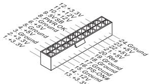
ATX 8-Pin Power Connector: JPWR2
This 8-Pin power connector is used to provide power to the CPU.
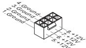
IMPORTANT
Make sure that all the connectors are connected to proper ATX power supplies to ensure stable operation of the mainboard.
Serial ATA Connector: (SATA1 ~ 2 for 870-SG45, SATA1~6 for 870-C43)
This connector is a Serial ATA interface port. Each connector can connect to one Serial ATA device.

IMPORTANT
Please do not fold the Serial ATA cable into a 90-degree angle. Otherwise, data loss may occur during transmission.
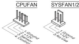
Fan Power Connectors: CPUFAN, SYSFAN1, SYSFAN2
The fan power connectors support system cooling fan with +12V . When connecting the wire to the connectors, always note that the red wire is the positive and should be connected to the +12V ; the black wire is Ground and should be connected to GND. If the mainboard has a System Hardware Monitor chipset onboard, you must use a specially designed fan with speed sensor to take advantage of the CPU fan control.
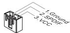
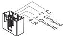
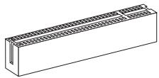
S/PDIF-Out Connector: JSP1
This connector is used to connect S/PDIF (Sony & Philips Digital Interconnect Format) interface for digital audio transmission.
CD-In Connector: JCD1
This connector is provided for external audio input.
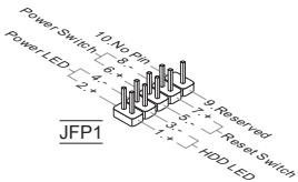
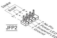
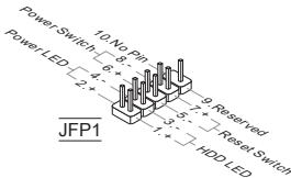
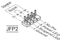
Front Panel Connectors: JFP1, JFP2
These connectors are for electrical connection to the front panel switches and LEDs. The JFP1 is compliant with Intel® Front Panel I/O Connectivity Design Guide.
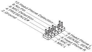
Front Panel Audio Connector: JAUD1
This connector allows you to connect the front panel audio and is compliant with Intel® Front Panel I/O Connectivity Design Guide.
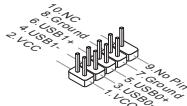
Front USB Connector: (JUSB1 for 870-SG45, JUSB1~3 for 870-C43)
This connector, compliant with Intel® I/O Connectivity Design Guide, is ideal for connecting high-speed USB interface peripherals such as USB HDD, digital cameras, MP3 players, printers, modems and the like.
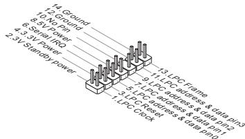
TPM Module connector: JTPM1
This connector connects to a TPM (Trusted Platform Module) module. Please refer to the TPM security platform manual for more details and usages.
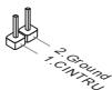
Chassis Intrusion Connector: JCI1
This connector connects to the chassis intrusion switch cable. If the chassis is opened, the chassis intrusion mechanism will be activated. The system will record this status and show a warning message on the screen. To clear the warning, you must enter the BIOS utility and clear the record.
PCIE Slot
The PCIE slot supports the PCIE interface expansion card.
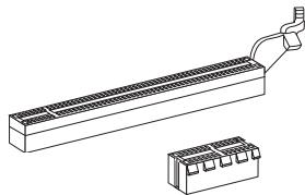
The PCIE 2.0 x16 slot
The PCIE x1 slot
PCI Slot
The PCI slot supports LAN card, SCSI card, USB card, and other add-on cards that comply with PCI specifications.
IMPORTANT
Make sure that you unplug the power supply first. Meanwhile, read the documentation for the expansion card to configure any necessary hardware or software settings for the expansion card, such as jumpers, switches or BIOS configuration.
PCI Interrupt Request Routing
When adding or removing expansion cards, make the IRQ, acronym of interrupt request line and pronounced I-R-Q, are hardware lines over which devices can send interrupt signals to the microprocessor. The PCI IRQ pins are typically connected to the PCI bus pins as follows:
| Order Slot | 1 | 2 | 3 | 4 |
| PCI 1 | INT A# | INT B# | INT C# | INT D# |
Clear CMOS Jumper: JBAT1
There is a CMOS RAM on board with an external battery power supply to preserve the system configuration data. With the CMOS RAM, the system can automatically boot OS every time it is turned on. If you want to clear the system configuration, use the button to clear data. Press the button to clear the data.


Keep Data

Clear Data
IMPORTANT
You can clear CMOS by shorting 2-3 pin while the system is off. Then return to 1-2 pin position. Avoid clearing the CMOS while the system is on; it will damage the mainboard.
BIOS SETUP
Power on the computer and the system will start POST (Power On Self Test) process. When the message below appears on the screen, press key to enter Setup.
Press DEL to enter SETUP
If the message disappears before you respond and you still wish to enter Setup, restart the system by turning it OFF and On or pressing the RESET button. You may also restart the system by simultaneously pressing
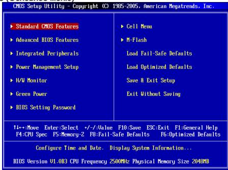
Main Page
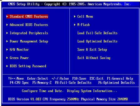
Standard CMOS Features
Use this menu for basic system configurations, such as time, date etc.
Advanced BIOS Features
Use this menu to setup the items of special enhanced features.
Integrated Peripherals
Use this menu to specify your settings for integrated peripherals.
Power Management Setup
Use this menu to specify your settings for power management.
H/W Monitor
This entry shows the status of your CPU, fan, warning for overall system status.
Green Power
Use this menu to specify the power phase.
BIOS Setting Password
Use this menu to set BIOS setting Password.
Cell Menu
Use this menu to specify your settings for frequency/voltage control.
M-Flash
Use this menu to read/ flash the BIOS from storage drive (FAT/ FAT32 format only).
Load Fail-Safe Defaults
Use this menu to load the BIOS default values that are factory settings for system operations.
Load Optimized Defaults
Use this menu to load factory default settings into the BIOS for stable system performance operations.
Save & Exit Setup
Save changes to CMOS and exit setup.
Exit Without Saving
Abandon all changes and exit setup.
Cell Menu
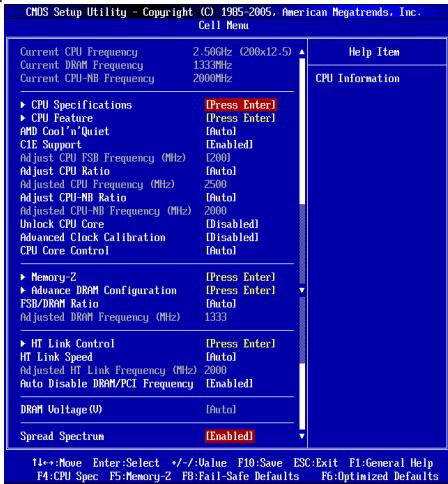
Current CPU / DRAM / CPU-NB Frequency
These items show the current clocks of CPU, Memory and CPU-NB speed. Read-only.
CPU Specifications
Press
CPU Technology Support
Press
CPU Feature
Press
AMD Cool'n'Quiet
The Cool'n'Quiet technology can effectively and dynamically lower CPU speed and power consumption.
C1E Support
To enable this item to red the CPU power consumption while idle. Not all poressors support Enhanced Halt tate (C1E).
SVM Support
This item allows you to enable/disable the AMD SVM (Secure Virtual Machine) Technology.
AMD Cool'n'Quiet
The Cool'n'Quiet technology can effectively and dynamically lower CPU speed and power consumption.
C1E Support
To enable this item to read the CPU power consumption while idle. Not all poressors support Enhanced Halt tate (C1E).
IMPORTANT
To ensure that Cool'n'Quiet function is activated and will be working properly, it is required to double confirm that:
- Run BIOS Setup, and select Cell Menu. Under Cell Menu, find AMD Cool'n'Quiet, and set this item to "Enabled".
- Enter Windows, and select [Start]->[Settings]->[Control Panel]->[Power Options]. Enter Power Options Properties tag, and select Minimal Power Management under Power schemes.
Adjust CPU FSB Frequency (MHz)
This item allows you to select the CPU Front Side Bus clock frequency (in MHz).
Adjust CPU Ratio
This item is used to adjust CPU clock multiplier (ratio). It is available only when the processor supports this function.
Adjusted CPU Frequency (MHz)
It shows the adjusted CPU frequency. Read-only.
Adjust CPU-NB Ratio
This item is used to adjust CPU-NB ratio.
Adjusted CPU-NB Frequency (MHz)
It shows the adjusted CPU-NB frequency. Read-only.
Unlock CPU Core
This item allows you to unlock the additional cores, you could set it [Enabled] and then set Advanced Clock Calibration [Auto] in order to be able to activate the processor cores.
Advanced Clock Calibration
This item is for overclock. Setting to [Auto] allows you to set the CPU Ratio higher. It is available only when the processor supports this function.
CPU Core Control
This item is used to control number of CPU cores. When set to [Auto], the CPU will operate under the default number of cores. When set to [Manual], you will be able to enable/disable the specific CPU core.
Core 1/2/3/4
These items are used to enable/disable the core 1/2/3/4.
Memory-Z
Press
DIMM1~4 Memory SPD Information
Press
Advance DRAM Configuration
Press
DRAM Timing Mode
Select whether DRAM timing is controlled by the SPD (Serial Presence Detect) EEPROM on the DRAM module. Setting to [Auto] enables DRAM timings and the following "Advance DRAM Configuration" sub-menu to be determined by BIOS based on the configurations on the SPD. Selecting [Manual] allows users to configure the DRAM timings and the following related "Advance DRAM Configuration" sub-menu manually.
FSB/DRAM Ratio
This item allows you to select the ratio of FSB/ DRAM.
Adjusted DRAM Frequency (MHz)
It shows the adjusted Memory frequency. Read-only.
HT Link Control
Press
HT Incoming/Outgoing Link Width
These items allow you to set the Hyper-Transport Link width. Setting to [Auto], the system will detect the HT link width automatically.
HT Link Speed
This item allows you to set the Hyper-Transport Link speed. Setting to [Auto], the system will detect the HT link speed automatically.
Adjusted HT Link Frequency (MHz)
It shows the adjusted HT Link frequency. Read-only.
Auto Disable DRAM/PCI Frequency
When set to [Enabled], the system will remove (turn off) clocks from empty DRAM/PCI slots to minimize the electromagnetic interference (EMI).
DRAM Voltage (V)
This item is used to adjust the voltage of memory.
Spread Spectrum
When the mainboard's clock generator pulses, the extreme values (spikes) of the pulses create EMI (Electromagnetic Interference). The Spread Spectrum function reduces the EMI generated by modulating the pulses so that the spikes of the pulses are reduced to flatter curves. If you do not have any EMI problem, leave the setting at Disabled for optimal system stability and performance. But if you are plagued by EMI, set to Enabled for EMI reduction. Remember to disable Spread Spectrum if you are overclocking because even a slight jitter can introduce a temporary boost in clock speed which may just cause your overclocked processor to lock up.
IMPORTANT
- If you do not have any EMI problem, leave the setting at [Disabled] for optimal system stability and performance. But if you are plagued by EMI, select the value of Spread Spectrum for EMI reduction.
- The greater the Spread Spectrum value is, the greater the EMI is reduced, and the system will become less stable. For the most suitable Spread Spectrum value, please consult your local EMI regulation.
- Remember to disable Spread Spectrum if you are overclocking because even a slight jitter can introduce a temporary boost in clock speed which may just cause your overclocked processor to lock up.
Load Optimized Defaults
You can load the default values provided by the mainboard manufacturer for the stable performance.

#
#
AM3 仿尼贝是AMD Phenom/Phenom/Althon II/Althon/ Sempron 形
CPU上
http://www.msi.com/index.php?func=cpuform2 聊话心事/
HyperTransport
Hyper Transport(HT) 3.0 建構脚手
#
- ニム・デリジ:AMD®770製装
- SuaUsS BrLrJt: AMD® SB710 6
J
DDR3 800/1066/1333/1600*(OC)SDRAM(8GB)
- 卸일 채일모드지원
(在汉)
http://www.msi.com/index.php?func testreport則查到志信。)
LAN
Realtek® RTL8111E (870-SG45) on the LAN 10/100/1000 Fast Ethernet 厂
Realtek® RTL8105E (870-C43)® élèse LAN 10/100 Fast Ethernet 購件
0
ATX24FJ1JFJFJFJFJFJFJFJFJFJFJFJFJFJFJFJFJFJFJFJFJFJFJFJFJFJFJFJFJFJFJFJFJFJFJFJFJFJFJFJ
i) Konnectre to useh aonmne nnnn swiitj and LED to ene hse h usc. JFP1 is Intel® Front Panel I/O Connectivity Design Guide to the use of
前庭部瓣尼O迪O肌版TA:JAUD1
i i Connectivity Design Guide will exceed.

前 用 ~ U S B ~ 卡 网 电 器 : ( 8 7 0 - S G 4 5 的 J U S B 1 , 8 7 0 - C 4 3 的 J U S B 1 3 )
| Order Slot | 1 | 2 | 3 | 4 |
| PCI 1 | INT A# | INT B# | INT C# | INT D# |
CMOS 装印机 JBAT1
PowerOnSelfTest()
and the first time is NOT 100% better than the second time.
DEL将不能生成,只能生成。
Current CPU / DRAM / CPU-NB Frequency (新旧CPU/DRAM/QPI 即合)
CPU Specifications (CPU Specification)
CPU Technology Support (CPU功能支持)
C1E Support (C1E 资源)
C1E Support (C1E 設用)
Adjust CPU FSB Frequency (MHz) (CPU FSB plus/total (MHz)
i
Adjust CPU Ratio (CPU bit to 0.9)
Adjusted CPU Frequency (MHz) (主锁回CPU主卡数) (MHz)
此哈默是主请到CPU主和数来印时自。
Adjust CPU-NB Ratio (CPU-NB bit to 0)
i
Adjusted CPU-NB Frequency (MHz) (主锁回CPU-NB 参加数) (MHz)
Adjusted DRAM Frequency (MHz) (JST-100) (DRAM JST-100)
HT Link Control (HT LInK3 KaeH)
Adjusted HT Link Frequency (MHz)(止詠則HTLHTK主卡) (MHz)
i
Auto Disable DRAM/PCI Frequency (DRAM/PCI 即加多子自通态)
[Enabled(音彥)]或上载完楚而用Sismei则BDRAM/PCI备果去里到的
DRAM Voltage (V)
i
Spread Spectrum (Dadechuk)
Press DEL to enter SETUP
Advanced BIOS Features
Integrated Peripherals
BIOS Setting Password
Current CPU / DRAM / CPU-NB Frequency
CPU Technology Support
Adjust CPU FSB Frequency (MHz)
Adjusted CPU Frequency (MHz)
Adjusted CPU-NB Frequency (MHz)
Advanced Clock Calibration
Adjusted DRAM Frequency (MHz)
HT Incoming/Outgoing Link Width
Adjusted HT Link Frequency (MHz)
ATX (19,0cm X 30,5 cm)
Montage
6 Montagebohrungen
Press DEL to enter SETUP
Advanced BIOS Features
Integrated Peripherals
BIOS Setting Password
Overclocking Profile
Current CPU / DRAM / CPU-NB Frequency
CPU Technology Support
Adjust CPU FSB Frequency (MHz)
Adjusted CPU Frequency (MHz)
Adjusted CPU-NB Frequency (MHz)
Advanced Clock Calibration
Adjusted DRAM Frequency (MHz)
HT Incoming/Outgoing Link Width
Adjusted HT Link Frequency (MHz)

KOMNOHEHTbI CNTeMHOn INaTbI
XAPAKTEPNUCTIKN
Ipoceccopby
■Погозбрь AMD®Phenoml/ Phenom Althon II/Althon/Sempron B KOHCTPyKTBVE AM3.
(Dля пооченья самою Новийнформаясу CPU, noceturre caHT http://www.msi.com/index.php?func=cpuform2)
HyperTransport
- ПобдевжkaTeXнологин Hyper Transport(HT) 3.0
YunceT
CebephmyoCT:AMD770
IOxHbIMoCT:AMD*SB710
NamrTb
DDR3 800/1066/1333/1600*(OC)SDRAM(8F6Max)
(3aDopepkka DyBXKAHANbHO rpeXIMa
http://www.msi.com/index.php?func=testreport)
LAN
Плобержka LAN 10/100/1000 Fast Ethernet на чincete Realtek® RTL8111E (дяг 870-SG45)
Плдержka LAN 10/100 Fast Ethernet на чincete Realtek® RTL8105E (дяп 870-C43)
Aydno
UnterpnpobAHbHnYncET Realtek ALC887
7.1-kanahbHoe ayno C n6Km npeha3naeHHem pa3bEMOB
CoBmecTImoCTb co cneunpkauNei Azalia 1.0
SATA
6 nopTOB SATA 3Γ6/c Na YunCeTe AMD® SB710 (Дя 870-C43)
2 nopTa SATA 3Γ6/c ha quinCeTe AMD® SB710 (Дяг 870-SG45)
KOHHeKTopbI
3aDne nane
-1PS/2npTMbIu
-1PS/2nopTKnabNaTpybI
-1 nocneIOBATEbHbI nopt
- 4 nopTa USB 2.0 (ДЯ 870-SG45)
- 6 nopToB USB 2.0 (dπ870-C43)
-1pa3bemLAN
-33ByKObBix pa3bemaC rN6KIM nepeHa3HaueHHeM
Pa3bembl, yTCAHOBJIeHHbIe Ha nIaTe
- 1 pa3bem USB 2.0 (Дпя 870-SG45)
- 3 pa3bema USB 2.0 (Дпя 870-C43)
- 1 pa3bem SPDIF-Out
- 1 pa3bem Дя подкюеця aydno Ha nepeedne nane
- 1 pa3bem daTcNka OTkpBbAHnK Kopnyca
-1pa3bem CD-In - 1 pa3bem TPM
Cnotbl
1 cnot PCIE x16
3cnotaPCIEx1
2 cnoTa PCI, noDepkka INTeppeca PCI uHbI c nTuHaem 3.3V/5V
ΦopM ΦakTop
ATX (19.0cm X 30.5 cm)
KpennneHne
6 O TBepCTn DnKpeHnneHn
Press DEL to enter SETUP
Main Page (OchOBHoe MeHIO)
Standard CMOS Features (CTaHapThbIe FyHKm CMOS)
3TO MEHIO N03BONJET YCTAOHBOT B OCHOHBIE napAMETpBI KOHNfhyprauCN CICTEMbI (DATy, BPMEY, n.T.D.).
Advanced BIOS Features (ДоюнтьньгфункиBIOS)
3To MeHIO nCnOJIb3yETcIg IaNHaCTPOIKN CneuaJIbHbIX ΦyHKcIINBIOS.
Integrated Peripherals (BCTpoehhble nepupepnhbye yctpoicta)
3TOmEHNOIbEyETcJnAHaTcPOIKnMapaMeTPOB BCTPOEHNbX npHHePnHbIXyctPOCTb.
Power Management Setup Setup (Hactpoika ynpablenia nitaHneM)
3TO MEHIO NO3BOJRAET 3aatab npametpbyl npabBHeHnI NITAHmE CNCTeMbI.
H/W Monitor (MoHTop annapaTHoY actn)
3TOT nyHKT OTO6pKaet COCTOHNe annapathOH Yactn PIK.
Green Power
3To MeHIO nCnOlb3yETcI dIg Ha3HaueHnpeXmAm NTaHn.
Exit Without Saving (BbIXoD 6e3 coxpaHene)
OTmeHa BCEx I3MeHeHn N BbIXoN I3 peXIMa HAcTpoKn.
Cell Menu

Current CPU / DRAM / CPU-NB Frequency
3TNyNHKtblNOKa3bIAIbOT KeTuSyIOcHToT CyPC,CKoPocTb NAMrTIu CPHN- NB. Tolbko dA rTeHNA.
CPU Specifications
HAnMMeTte
CPU Technology Support
HakMMTE
CPU Feature
HaxmTe
AMD Cool'n'Quiet
TexHONOOL Cool'NeiQo3noAe3fKeTHNBO HnAMHmueCKH 3MmEHTb aactOTy CPU nHEcNOTpe6bnne HcIcTeMbI.
C1E Support
BKIOVHTE 3OTN yNTKJN DTHCNKHEHNEBEPRONOTpeBENHCA, KORaOH no paOtaER. He bcne npoeccocbi Npndepkmbaiot Enhanced Halt state (C1E).
SVM Support
3TOT NyHK TNOBONAEI BKNIOAaBbIKIOaTH TEXHOrO AMD SVM (Secure Virtual Machine).
AMD Cool'n'Quiet
TexHONORHa Cool'NQuiet noBONReT 3ΦΦeTKBHO DnHAMMueCKN 3MHeHTb 卷CTO CPU nHEperonrTope6neHHNE CHTeMbI.
C1E Support
BKJNUHTE 3OTN yHNTI KN CHMENHNA 3HEPONOTpe6NEHNA CUP, KORda OH He paOtaETa. He Bc NPoueCCoBp NOpDePKbAot ENoted Halt state (C1E).
BHIMAHHE
YChb6y6BnTcB TOM, YTO texHONrora Cof'n'Quiet BKnIOHena n paBotaet npabInbHo, HeoXOaHMo:
3aIbn B nporpaMny BIOS Setup, n bIb6pabT Cell Menu. NaHdnte AMD Cool'n Quiet noct Cell Menu, u yctahonbHrE o r e "Enabled" "Enabled".
* B Windows BBbepurte [Start]->[Settings]->[Control Panel]->[Power Options], Boiiune B Power Options Properties, BBbepurte Minimal Power Management noD Power schemes.
Adjust CPU FSB Frequency (MHz)
3TOT nyHKT no3BOJRAET perylnipOBaTB qactOry FSB npouecoppa (B MfU).
Adjust CPU Ratio
3TOT nyHKT cNcONbEyTC dnerpyeNPOBKO MHOKHTen pOueccpo. OH DoCTyHn TohLo KOrTa KOrDa npOecCOP NoDaePKBaET 3Ty FHyKNIOU.
Adjusted CPU Frequency (MHz)
3TOT nyHKT noka3bIbae TekuSyu qactoty CPU. ToIbKO dnyTeHnA.
Adjust CPU-NB Ratio
3TOT nyHKT nCnOJIb3yETc dIЯpeRynipOBKn cactoTBi CPU-NB.
Adjusted CPU-NB Frequency (MHz)
3TOT nyHKT noka3bIaET TekyuTo yacToTy CPU-NB. TOnbKO dnyTeHnA.
Unlock CPU Core
3TOT NYHT NIOBONET PA36NOKIPOBATb DONOHNHTe HYNCTbl, BAM MOKHO yctAHOBINT bE [Enabled] NTOM YCTAHOBINT Advanced Clock Calibration B [Auto], YTO6b IMETb BO3MOXHOCTb AKTNBI3POBATb npOECOPHbye YCNCTbl.
Advanced Clock Calibration
3TOT NYHK TNCNBJ3yETC DnA pa3ROHa. YCTAHOBKa B [Auto] no3BONJET yCTAHOBt bactOty CPU bIe. OH doCTynen TOnbKO Torda, KOrDa npoecccp NOdJeKbNAeT 3Y fHyKnIO.
CPU Core Control
3TOT NYHK NcOINb3yETcA DnI KOHTpONIOBAHNHO HOMepa npoecccophoro YHNCeta. PnI yctahOBKe B [Auto], CPU paOtaeT noD homePom YHNCetOB no yMOnUHNO. PnI yCTaOHBe B [Manual], BAM MOXHO BKNIOATb/BkIOuOaTB onpeEneHHbYHNCET CPU.
Core 1/2/3/4
Tn NyKtbI NcNoJIb3yIOCTa IINB KInHouEHHa/BbIKHIOUeHHa YINCeTOB 1/2/3/4.
Memory-Z
HaxmTe
DIMM1~4 Memory SPD Information
Hakmite
Advance DRAM Configuration
HaxmTe
DRAM Timing Mode
OnpeIeIeIe 6ydt IINBpeMeHbIe npaMeTpbl DRAM KOHTpOIIIOBaTcBaaDnHbIM n3 SPD (Serial Presence Detect) EEPROM MaNoSyte DRAM. PInB bBy6Obe 3NaueHHa[Auto], BpeMeHbIe npaMeTpbl DRAM, BKNIOaYNUKbTI MeHIO, nepeUcnEHNbIe Nnke, yCTaHaBImBAIOrCA BIOS B COOTBeTCTBmC daHbIMn m3 SPD.PnIP yCTaHOBe 3NaueHHa[ManuAI], 3OT pNtIK NTBOJIeR BPnuHyIO perynIpObaTb BpeMeHHbIe npaMeTpbl DRAM DOCTUYHbIe B 3TOM MeHIO.
FSB/DRAM Ratio
3TOTyHKITNo3BONJET peryIINPOBaTB Ko3ΦΦnIeHT MEXdy Chactotamf SFB n naMBAbI.
Adjusted DRAM Frequency (MHz)
3TOT nyHKT noka3bIbaet 3haeHne yacToIb I naMrtn. ToIbKO dnyTeHna.
HT Link Control
HaxmTe
HT Incoming/Outgoing Link Width
3ToT nyHKT onpeJeIeR TwnHny BxOJaIeMxCXoJaIeJnHnH HT. Ppn yctahOBKe B [Auto], cncTeMa aBtOMaTHueCKN onpeJeIeR TwnHny SInhbl HT.
HT Link Speed
3TOT nyHKT no3B0JAEY cTahOBInb ckOpCTb nepeDaHn NO uHHe HyperTransport. PtN yctAHOBKe B [Auto], CNTeMa ABtOMaTHueckn onpeDeJeRt ckOpCTb uHnHb HT.
Adjusted HT Link Frequency (MHz)
3TOT nyHKT noka3bIbaeTe kTu yio uactOtu uHbI HT. TOnbKO dnyteHnA.
Auto Disable DRAM/PCI Frequency
Pn yctahOBKe 3aueHInr [Enabled], CnCTeMa OTKnIOHT HeNCN0N3bYeMeIbe pa3BeMbI namTIN PCI, YTO npBedeT K cnHexeHIno yOboHn 3neKtporAmHnTHbIX nomex (EMI).
DRAM Voltage (V)
3TOT nyHKT no3BONrE peryInpObaTb HanpJKeHne naMaTn.
Spread Spectrum
Tak kak taktobbl rhehepatop cnctemho nlahtbIMnylbcbl, to ero paobota Bblbbaet 3neKTPOMARHnHbIe NOMEXN - EMI (Electromagnetic Interference). ΦHykzma Spread Spectrum cHnkaet 3tn NOMEXN, rheneppyr crnaKeHHbe IMnYNbSb. Ecny u bac HET npO6bnm C nomexamn, octabte 3haeHene [Disabled] (3anpeuho) dner lyuwei ctabinbHOCTn i pnonBodntelbHOCTn. Ondako,
ecny Bac BO3NHKAJOT 3NEKTPOMAHTNTHbIe NOMEHX, pa3peWNTE NCNOB3OBAHne 3OTOn FyHKUcY, yCTAHOBIN [Enable] (pa3peSHEO). He 3a6bYte 3anPertntb NCNOB3OBAHne FyHKUcIM Spread Spectrum, ecny Bbl «p3a0rHReTe» CnCTEMHyO nTnay. 3TO He06XoDMIO, tak KaK dAnke He6bONuDpe6e3r CnHApOB TAKTOBO rTatebopA MoKET npVBcEtN K OTKaYs «p3a0rHaHHoro» npOceccopa.
BHIMAHHE
- Ecnny y Bac Het npobnem c nomexamn, octabte 3nauehme [Disabled] (aanpeuho) nianyue stcbnBHOCTN n pno3BODHTNBHOCTN. Ondako, ecnny y Bac BO3HnAoiT neKETPOMarHnTHbIe nomexn, BbIbepTe Spad Spectrum dny xmyEHEWHeia.
* Yem 6oIbIwe 3aHaeHne Spread Spectrum, tem Hnke bdyet ypoBHeN 3eKTPOMAHHTHbIX NOMEX, HO CNTcema cTahET MeHEE cTaONbHOJ. IyBa IbIObe NOxOJaIeO 3HaueHne SpuR eumS TcBpeTc Bo 3aHaeHneMm ypoBHeN 3eKTPOMAHHTHbIX NOMEX, yCTaHOJIeHHbIX 3AKOHDoTeNbCTBOM.
* He 3a6yblte 3anp9tntb IcnoIb3oBaHne FynKcnn Spread Spectrum, ecn Bby (pa3roHnEeT) CNTeMThy nIaTy. 3To He6xOJIMMo, TAK KaK DaJke He6onlsuon dpe6e3r CInHAnoT TaKTOBOr ReHepatopA MoKeT npINBeCTN K OTKa3y (pa3orHaHHoro) npOceccopa.
YcTaHOBka 3HaeHnI NO yMOHTaHmIO
IaTCTa6HbIOb PAoBcTOI CNTBMcI BIO MKeOTe 34yBHTnB HcTPOBNI BOS NOUUMHOYU, yOtaHOBNEHNBE IpoN3BDIOITENEM CNTTEMHOIIATb.

简体中文
简介
Press DEL to enter SETUP
| CNBS Setup Utility - Copyright (C) 1985-2005, American Megatrends, Inc. | |
| Standard CNBS Features | Cell Menu |
| Advanced BIOS Features | M-Flash |
| Integrated Peripherals | Load Fail-Safe Defaults |
| Power Management Setup | Load Optimized Defaults |
| H/V Monitor | Save & Exit Setup |
| Green Power | Exit Without Saving |
| BIOS Setting Password | |
| 1...Move Enter;Select +/-/Value F10;Save ESC;Exit F1:General HelpF4-CPU Spec F5:Memory-Z F0-Pall-Safe Defaults F6-Optimized Defaults | |
| Configure Time and Date. Display System Information...BIOS Version U1.0GB3 CPU Frequency 2500MHz Physical Memory Size 2040MB | |
CPU Specifications (CPU 属性)
CPU Feature (CPU 功能)
按下
AMD Cool'n'Quiet
Adjusted CPU Frequency (MHz) (調整後CPU頻率)
本項顯示調整後CPU的頻率。唯讀。
Press DEL to enter SETUP
(卡一押七設定画面を呼出)
Integrated Peripherals (內藏機能の設定)
CPU Technology Support (CPUtek-口一
CPU Feature (CPUの機能)
AMD Cool'n'Quiet
C1E Support (C1Eサボ一ト)
C1E Support (C1E 求一卜)
DRAM Voltage (V) (DRAM電圧)
×モリの電圧を調整いたします。
Spread Spectrum