WS 1613-ITC - Weather Station LA CROSSE TECHNOLOGY - Free user manual and instructions
Find the device manual for free WS 1613-ITC LA CROSSE TECHNOLOGY in PDF.
Download the instructions for your Weather Station in PDF format for free! Find your manual WS 1613-ITC - LA CROSSE TECHNOLOGY and take your electronic device back in hand. On this page are published all the documents necessary for the use of your device. WS 1613-ITC by LA CROSSE TECHNOLOGY.
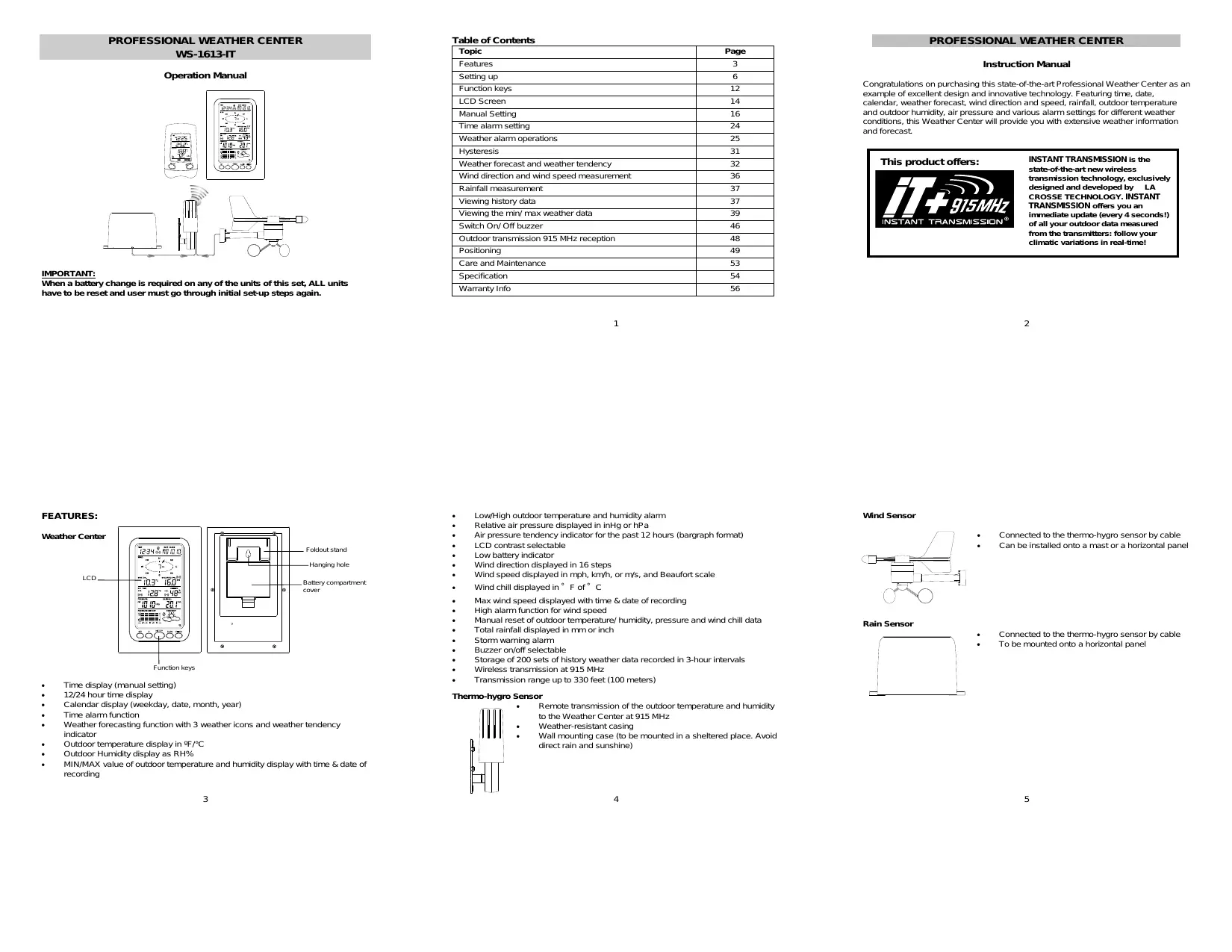
USER MANUAL WS 1613-ITC LA CROSSE TECHNOLOGY
SETNING UP: 2915 Me terre dar Me sensor me D: Rain sensor —_— naine themmo-hygre The radio communication between the receiver and the transmiter in the open field reaches distances of max 330 feet, provided there are no interfering obstacles Such 5 buildings, trees, vehicles, high voltage lines, etc.
11. Radio interferences created by PC screens, radios or TV sets can in some
cases entrely eut off radio communication. Please take this into consideration when chaosing standing or mounting locations. + Aterbateres are installed in the transmiter, instal the batteries in the weather center and the bonus recelver receive the signal rom the transmiter as Son as possible. Ifthe weather center is powered more than 5 hours after the ansmiter is powered, the weather center wil never receive signal successfully from this transmiter. In this case, user wil need to reinstal the batteries from the transmiter o redo set-up procedure. + Aterbateres are installed, there will be synchronization beteen weather center and the transrmiter. AL is time, the signal reception icon will be binking, (When the signal is successful received by the weather center, the icon wi be suitched on. (IIS not successful, the icon will not be show in LCD) So the {user can easily see whether the last reception was successful (icon on) or not ‘icon of. On the other hand, the short blinking of he icon shows that: à reception is in progress. Note: When puting the Weather Center into operation, is important to perforn in close proxdmity (e.g. on à table) à complete wring and set-up of the system Thé step is important lo test al components for coect function before placing and mounting them attheir final destinations (See Pasitioning below)
1. Unwind the cables of the Rain and the Wind sensors. Connect the Rain and the
Wind sensors 10 the Thermo-hygro sensor by plugging the connector heads of the to sensors into the appropriate sockets of the Therro-hygro sensor.
2. Firstinsert the batteries into the Thermo-hygro sensor (see ‘How to install and
replace the batteries into the Thermo-hygro sensor” belo)
3. Then insertthe batteries into the Weather Center (see “How to install and
replace the batteries into the Weather Center” below). Once the batteries are installed in the Weather Center, all segments of the LCD il light up briefly and à short signal tone vrll be heard. wl then display the Be a 12:00, he date
“rranamiser signal S recepion icon + ifihe signal reception is not-suecessful on the first frequency (915MHz) for 14 Seconds, the frequency is changed to 920MHz and the learning Is wied another 14 seconds. st not successful the reception Is Wied for 14 seconds on 910MHz. This wl also be done for re-synchronization. HOWTO INSTALL AND REPLACE THE BATTERIES INTO THE THERMO-HYGRO SENSOR ‘The outdoor Thermo-hygro sensor orks with 2 x'AA" IEC | | LRG 1.5V batteries. To install and replace the batteries, please follow the steps below LUninstall the rain cover of the transmiter. 2.Remover the battery compartment cover. = Zinsert the bateries, obsenving the correct polarty (see the mañdng in the battery compartment. LI 4.Replace the batery cover and the rain cover onto the unit. Aote: In the event of changing batteries in any of the unis, all units need 1 be reset by following the seting up procedures. This is because a random security code is assigned by the thermo-
will be shoum for. 5 1.1.05, the weather icons, and air pressure value. * outdoor data. à. Aferverds, the Weather Center vil start receiving data from the transrrter. ‘The outdoor temperature, humidity wind chil and wind speed should then be displayed on the Weather Center. this does not happen after 30 seconds, the batteries val need to be removed from both units. You val have to start again from step 1.
5. You maythen check al cables for correct connection and al components for
correct function by manualy tuming the wind-gauge, moving the eather:vane, ing the rain sensor lo hear the impact of the intemaly moving seesaw, etc. {See Positioning below.
6. Time and date shall be manual) set (See Manual Setting below).
‘After the Weather Center has been checked for correct function wi regarc to the above points and found ft, the intal set up of the weather station system is finished and the mountng of the system components can take place. IE must be ensured however that all components work proper Igether al their chosen mourting or standing locations. I e.g. there appear to be problerrs with he 915 MHz radio transmission, they can most be overcome by slighty changing the mourting locations.
8. Insertihe baterles into the Bonus Receiver (see ‘How to install and replace
the batteries into the Bonus Recelver” below).
9. Once the batteries are installed, al segments of the LCD wil light up brief. I
wäl then display the time as 12:00 and the Indoor terrperature.
10. | The outdoor temperature and huridity will be display after reception of data
from the wansmiter. If this does nothappen after 1 minute, the batteries will need to be removed from all the units. You wall have Lo start again from step 1. Note: Please refer to the “Bonus Receiver functions and settings” below.
hygro sensor at start-up and this code must be received and stored by the Weather Center in the first 30 seconds of power being supplied to I. HOW TO INSTALL AND REPLACE THE BATTERIES INTO THE WEATHER CENTER The Weather Center works with 3 x AA, IEC LR6, L.SV batteries. When the batteries need to be replaced, the low battery syrrbol vil appear on the LcD. To instal and replace the batteries, please follow the steps below:
1. Rerve the batery corpartment cover.
2. insertthe bteries obsening the correct
polariy (see the making in the battery compartment).
3. Replace the battery cover.
The Bonus Receiver use 2 x AA, IEC LRG, 15V -=-=. | batteries. When the batteries need to be replaced, the f lou battery syrbel vil appear on the LCD. f To instal and replace the batteries, please folow the steps below. sel 1. Rermve the battery corrpartment cover.
2. Insertihe batteries observing the correct polarty
{see the marting in the battery corrpartment}
3. Replace the battery cover.
BATTERY CHANGE: Ibis recommended lo replace the batteries in all units every 24 months to ensure optimum accuracy of these unis. Please participate in the preservation of the environment. Retum used batteries to an authorized depot. Note: ‘The stored History record vil not be kept after the battery change is done on the Weather Center. IMPORTANT: Wihen a battery change is required on any of the units of this set, ALL units. have to be reset and user must go through initial set-up steps again. See “Setting up” above.
cd S The LCD contrast can be set within 8 levels, from LCD 1" 10 "LCDE" (defaut seting is LCD 5)
3. Confimwihthe SET key and enter the MANUAL TIME SETTINE
+ Press to adjust (increase) the level of different settings + Stop the alarm during the üme alarm or weather alarm ringing + Press to confim resetthe maw/min record HISTORY key + Press display the weather data history records + Stop the alarm during the üme alarm or weather alarm ringing + Press Lo ext manual seting mode and alarm setting mode ALARM key Press lo enter the time alarm and weather alarm seting mode Confim particular alarm setting Press D exit the manual setting mode Stpp the alarm during the time alarm or weather alarm ringing Press t ex max/ min record display mode PANMAX key + Press b display minimum and mxämumrecords of various weather data + Press to adjust (decrease) the level of different setings + Stop the alarm during the üme alarm or weather alarm ringing LCD SCREEN The LCD screen is split into 5 sections displaying the following information:
Wind data Outdoor terrperature and huridity, Air pressure and Rainfall data Air pressure history and Weather forecast.
MANUAL TIME SETTING: You then may manually setthe time of he clock by following the steps below: Minutes fashing #80! Eh ‘The hour gi wil start flashing; Use the +or MIN/MAX key o setthe hour. Press the SET key to switch to the minutes. The minute digjt vil start flashing Use the +or MINMAX key lo setthe minute. Confirm the time with the SET key and enter the 12/24 HOUR TIME DISPLAY SETNNG. 1274 HOUR TIME DISPLAY SETTING:
The time can be set to view as 12-hour or 24-hour format. The defaut tme display mode is 12-h, To setto 24-h time display:
1. Use the +0r MIN/MAX key 1 toggje the value.
2. Confimwihthe SET key and enter the CALENDAR SETTING.
CALENDAR SETING: Date. Month (for 24h te display) Morin. Date (fr 12e spy) DATE nue" U tu The date default of the Weather Center s 1. 1. of year 2005, The date can be set manually by proceeding as follous. ‘The year di start flashing
2. Use the +or MIN/MAX key 1 setthe year. The range runs from 00" (2000) to
3. Press the SET key to confimthe year and enter the month setting, The month
ft wl stat flashing,
4. Use the +or MIN/MAX key 1D setthe month
5. Press the SET Key to confimthe month and enter the date setting mode. The
date digi vil! start flashing.
6. Use the +0r MINMAX key t setthe date.
7. Confimm al calendar setings th the SET key and enter the “FC
Flashing ‘The current relative pressure value will start flashing
2. Use the +or MIN/MAX key o increase or decrease the value. Continually
holding the key wil allow the value to increase faster.
3. Confimwihthe SET key and enter the WEATHER TENDENCY SENSITIVITY
VALUE SETNING. This feature is useful for those who Ie at elevations above sea level but want their air pressure display to be based on sea level elevation.
WEATHER TENDENCY SENSITIVITY LEVEL SETTING
PRESSURE “nn Fasbirg——— (js DITES You may select a definite swiching sensliuity value, .06, .08, or .12 InHg for the change in the display of weather icons. This represents the “senciiuty" of the weather forecast {the smaller the value selected, the more sensitive the weather forecast. The default value 15 0.09 ing.
2. Use the +or MIN/MAX key to bggle between F" or "C".
3. Confimwiththe SET key and enter tre WIND SPEED UNIT SETTING
MPh The ind speed uni can be set as mph (rie per hour), kmyh (kilometer per hour), or 1198 (mater per second. The default unit is mph.
1. Use the +or MIN/MAX key 1) toggle betmeen the unit “mph”,“Kmyh" or vs”
2. Confimwihthe SET key and enter the RAINFALL UNIT SETTING.
Inch — = The total rainfall unit can be setas inch or rrm The default unit is inch.
1. Use the +0r MIN/MAX key 1) toggle betmeen the unit inch or "mm
2. Confimthe unit with the SET key and enter he RELATIVE AIR PRESSURE
3. Confmwiththe SET key and enter the STORM WARNING SENSMIVITY
STORM WARNING THRESHOLD VALUE SETTING
You may also define à swtching sensithty value for the Storm waming display at a decrease of air pressure from .08 ing to .27 inHg over 6 hours (Default 0.15 inH). PRESSURE panne" {Gus
1. The sensivity value will start ashing.
2. Use the +or MINMAX key o select the value.
3. Confimwihthe SET key and enter the STORM ALARM ON/OFF SETTING.
STORM ALARM ON/ OFF SETTING
You may also choose Lo switch On or Off the acoustic Storm waming alarm (Default OFF)
3. Confmwiththe SET key and the normal display mode will be shown.
InhE The relative air pressure can be set as ing or hPa. The default uni is in.
1. Use the +0r MIN/MAX key 1) togge betmeen the unit Hg” or “hPa”
2.Confrmthe unit with the SET key and enter the RELATIVE PRESSURE REFERENCE VALUE SETTING.
RELATIVE PRESSURE REFERENCE VALUE SETTING
The default reference pressure value of he barometer is 29,91inHg when batteries level). Ask for the current atmospheri pressure of your home area (Local weather Senice, ww, opiician, callbrated instruments in public buldings, airport). The relative air pressure can be manualy set to another value within the range of
in case a storm waming alarm is actvated, he dourward weather tendency arrow Wil be flashing. (Also see WEATHER TENDENCY INDICATOR below)
(TO EXIT THE MANUAL SETTING MODE
To exithe manual seting anytime during he manual setting modes, press the ALARM key (or HISTORY key) or wa for the automatic timeout. The mode will return to the normal üme display.
The alarm time can be set by the use of the ALARM and SET key.
1. Press the ALARM key once. The ALARM" icon and time dits are shown atthe
2. Press and hold the SET key for about 2 seconds. The hour igit of he alarm
time will star flashing. Press the + or MIN/MAX key to set the hour of he alarm te.
3. Press the SET key to confimm and advance to the minute setting. The minute
Gigi wi be flashing. A. Press the +or MIN/MAX key setthe minute of the alarm time. Press the (ALARM key to contirm, Wait for about 30 seconds and the display él retum to normal display mode automatically.
5. Inthe normal display mode, press the ALARM once key to go 1 the time alarm
seting mode again. Then press short the SET key switch on or of the me alarm (The showing of the icon ({(+)) means that-tre time alarm is switched on.)
6. Press the HISTORY key or wait for about 30 seconds and the display wa retum
to normal display mode automatically. The alarm inging duration is 2 minutes. To stop the alarm, press any ey during the alarm ringing,
WEATHER ALARM OPERATIONS
The Weather alarrré can be set when certain weather conditions are met according to your requirements. For exarrgle, you can set the thresholds for the outdoor temperature to H104°F (+40°C) (high) and 14°F (10°C) (low while only enabling the High alarm and disabling the low alarm (Le. temperatures <LAF (-10°C) ont igger Alarm, but temperatures >-H104F (40°C) wil.
te SET key 1D switch on or off the alarm. (The showäng of the icon (((+)} means. that the alarm is suitched on.) A. Press the ALARM key once. The Low Outdoor Terrperature alarm display vil be shoun,
5. Press and hold the SET key for about 2 seconds. The temperature digi will start
the SET key to switch on or ff the alarm. (The showäng of the icon (((+)} means: that the alarm is suitched on.)
7. Press the HISTORY key or ai for about 30 seconds and the display wi retum
to normal display mode automatically. In case the temperature velie meets the condition for high alarm or low alarm, the value will be blinking, along with the corresponding icon ("HI AL"/"LO AL"). And the buzzer wi ing for 2 minutes. User Ihen may press any key to stop the ring. User may quit the alarm seing and return to the normal display mode by pressing the HISTORY key. HIGH AND LOW OUTDOOR HUMIDITY ALARM SETTING: Note: The High and Low outdoor humidity alarm can be set OrvON independent according ‘© your needs.
eau Si on mean — High uns EDS Siren The Weather Center can be set alert when a specific weather condition is reached. ‘The following Weather Alarm settings can be adjusted in the ALARM setting mode. High outdoor temperature alarm Low outdoor temperature alarm High outsoor humiey alarm Low outdoor humidiy alarrn High wind speed alarm
Setthe Outoor temperature alarm value (High or Low alarm value):
Huridity alarm display wâl be shown. HUMDT ma y % te) sh te) 8
2. Press and hold the SET key for about 2 seconds. The humidity digi will Start
the SET key LD switch on or ff the alarm. (The showäng of the icon (((+)} means: thatthe alarm is suitched on.) A. Press the ALARM key once. The Low Outdoor hurridity alarm display wall be shoun.
5. Press and hold the SET key for about 2 seconds. The humidit digi will Start
the SET key LD switch on or ff the alarm. (The showäng of the icon (((+)} means. that the alarm is suitched on.) 7... Press the HISTORY key or wai for about 30 seconds and the display wi retum to normal display mode automatically. In case the humidity value meets the condition for high alarm or low alarm, the value il be blinking, along wéth the corresponding icon (“HI AL”/"LO AL"). And the buzzer vil ing for 2 minutes, User may press any key to stop the sound.
Default alarm values: w_[rv0 Tenpere Vion for wave RaaiNe Low | 45% Huridiy Hion_— | 70% Wine speed | High | 62 0mpn (ro0En HIGH AND LOW OUTDOOR TEMPERATURE ALARM SETTING: The High and Low outdoor temperature alarm can be set OnvON independent, according to your needs. Setthe Outoor temperature alarm value (High or Low alarm value) :
1. Inthe normal display mode, press the ALARM key ice. The High Outioor
Terperaure alarm display will be shown our rewP High aammicon — HAL (28° ON on
2. Press and hold the SET key for about 2 seconds. The temperature digi will start
The High wind speed alarm can be set by following the steps below.
2. Press and hold the SET key for about 2 seconds. The ind speed digit vil start
the SET key LD switch on or ff the alarm. (The showäng of the icon (((+)} means: that the alarm is suitched on.) A. Press the ALARM key once 1 retum to the norral display mode. In case the wind speed exceeds the condition for high wind speed alarm the value il be flashing, along with the corresponding Nigh alarm icon ("HI AL"). And the buzzer ll ing for 2 minutes. User may press any key 1o stop the sound. HYSTERESIS To compensate for fluctuation of the measured data, which may cause the weather Alarm t sound constant ifthe measured reading is close to your set level, à hysteresis function has been implemented for each weather alarm. For example, the High temperature alarm is set to +77°F (25°C) and the current value moves 1 477°F (25°C), the alarm vil be actvated (fit has been enabled). Now when the terrperature
drops to 476.8/F (24.9°C) or below and thereatter again increases to beyond 477-F (25°C), the data val be blinking, but no alarm wil be activateel. IE has to drop 1D below +75.2°F (24C) (uñth a pre-sethysteresis of 1.8 (1°C)) so that the alarm can be produced again. Hysteresis values for the various weather data 1ypes are given in the folloning table: Weather de Hysmresis rerrperaiure ES) Humty RH Wind speed ET Note: The temperaure or humidity data wi keep on flashing even after a key has been pressed 1 stop the alarm or buzzer has been swched off, to indicate that the current weather condiion s out of the pre-set mis)
WEATHER FORECAST AND WEATHER TENDENCY
WEATHER FORECASTING ICONS: Weather forecasting icons is displayed in any of the following combinations atthe right bottom part of LCD: à .E ce? AIR PRESSURE HISTORY (ELECTRONIC BAROMETER WITH BAROMETRIC PRESSURE TREND) The bottom section of the LCD also shows the relative air pressure value and the air pressure history. Depending on programming condiions, display of the history of air pressure in for of à graph consisting of vertical bars. The bar graph of the electronic barometer shows the air pressure history of the past: 12 hours in five 3-hour steps. PRESSURE HISTORY
A7 ge mipa LC] Vo U On n On ner The horizontal axis represents the last 12 hours air pressure recording (-12, -9,-6, 3 and 0 hour). The bars are plotied at each of he 5 steps and give the trend over the recorded period. The scale on the right compare the result The "0" in the middle of this scale determines the current air pressure. The vertical axés represents the air pressure changes in inHg (40-12, 40.06, 0, -0.06, -
12. The "0" represents the current air pressure). The newy measured pressure Was
compared 1 the previously recorded pressure reading. The pressure change is expressed by the difference between the current ("Oh") and the past readings in sion of 42 hPa or 40.06 InHg. the bars are Hising i indicates that the weather is geting better due to an increase in air pressure. Ifthe bars go dou it indicates à
For every sudden or significant change in the air pressure, the weather icons wi update accoringly to represent the change in weather. Every time a new average pressure value has been obtained (once per minute), this value is compared with an intemal reference value. the difference between these values is bigger than the selected weather tendency senstiviy, the weather-icon changes, either for worse or for better. In this case, he current pressure value becomes the new weather tendency reference.) Ifthe icons do not change, either the air pressure has not changed or the change has been 190 smal for the Weather Center 1 register. So you may adjust he "sensitty" f the pressure change checking in the setting mode -See WEATHER TENDENCY SENSMVITY VALUE SETTING above. However, ifthe icon displayed s à sun or raining cloud, there will be no change of icon Ifthe weather gets any beter (nith Sunny icon) or worse (with rainy Icon) since the icons are already at their extreres. The icons displayed forecasts the weather in terme of geting better or orse and not necessary sunny or rainy as each icon indicates. For example, the current weather 1s cloudy and the rainy icon Is displayed, I does not mean that the products fault because itis not raining. IL simply means that the air pressure has dropped and the weather is expected 1) get worse but not necessary rainy: Note: Aller seting up, readings for weather forecasts should be disregardea for the next 12- 24 hours. This wil allow sufficient me for the Weather station to collect air pressure. ‘data at a constant alitude and therefore resut in à mare accurate forecast.
drop of the air pressure and the weather is expected 1) get worse from the present
At every ful hour the current air pressure is used as a basis for the display of a new graph bar. The exsting graph is then moved one column to the left. Note: For accurate barometrc pressure trend, the Weather Center should operate at the same altude. For example, should not be moved. Should the unit be moved, or instance from the ground t the second floor of he house, the readings for the next 12-24 hours shall be discarded.
WIND DIRECTION AND MIND SPEED MEASUREMENT
In normal display mode, the second section of the LCD shows the following wind data. + Wind direction (shown onthe a compass scale of 16 divisions) and wind spaed in Beaufort scale + Windchilin°F er °C 2 Wind Speed in mph, km orme Tex showing wind speed in Beaufor scale
curenty detected wind mo ou © moyen al — re sommet ne ME A am ii, nach Common to weather forecasting, absolute accuracy cannot be guaranteed. The weather forecasting feature is estimated to have an accuracy level of about 75% due Lo the varying areas the Weather Center has been designed for use. In areas that experience surdden changes in weather (for exarple from sunny Lo rain), the Weather Center wi be more accurate compared to use in areas where the weather is stagnant most of the time (for example most sunny If the Weather Center is moved to another location significantly higher or lower than is inhial standing point (for exarrple from the ground floor to the upper floors of à house, discard the weather forecast for the next 48-60 hours, as he Weather Center may mistake the ne location as being à possible change in air-pressure when really itis due to the Slght change of altitude.
WEATHER TENDENCY INDICATOR
Werling together véth the weather icons is the weather tendency indicators (arrow located on the left and right sides of the weather icons). When the indicator points; upsards, means thatthe air-pressure Is increasing and the weather Is expected to improve, but when indicator points dowrwards, the air-pressure is dropping and the weather Is expected to become worse. Taking th into account, one can see how the weather has changed and is expected Lo change. For example, if he indicator is pointing dourwards together with cloud and Sun icons, then the Last notceable change in the weather was when IL was sunny (the Sun icon ony). Therefore, the next change in the weather vil! be cloud with rain icons Since the indicator is poinüng dounwarcks. Note: ‘Once the weather tendency indicator has registered a change in air pressure, Iwâll remain permanent} visualized on the LCD.
RAINFALL MEASUREMENT The total rainfall measurement is displayed in the fourth section of the LCD, in the unit of mm or inch. (see IEWING THE MIN/MAX WEATHER DATA belou) CHER
VIEWING THE HISTORY DATA
The Weather Center can store up to 200 sets of weather data which are recorded automatically at 3-hour intervais after the weather station is powered up, atthe nearest time of 0:00, 03:00, 06:00, 09:00, 12:00, 15:00, 18:00 and 21:00. For instance, if user has manually setthe time as 14:52 aîter Instaling batteries, the frst History record will be made at the coming 15:00 automatically, Then the second record wl be on 18:00 and so on. Each weather record includes the Wind direction, Wind speed in Beaufort scale, Wind chi temperature, wind speed, Outdoor temperature and huridity, relative pressure and total rainfal, pressure story and weather tendency. Also, the time and date of recording vil be displayed Note: in erder to acquire the correct me of recording of the history recorcs, you shall manually setthe current üme as soon as instaling batteries to the Weather Center. Aferwards, you should avoid changing the pre-set time as it will also alter the recorded "me of recording" of each history record, which may lead 19 confusion.
‘To views the weather history:
1. Press the HISTORY key. The latest weather record vil be shown th the date
and üme of recording. The “HISTORY" icon vil be displayed at the bottom of the LCD. nn 12:34 ox AD 1 10,
2. Press MIN/MAX to view older records.
{Press MIN/MAX and + key to view "Previous" and Next” record respectively. The records are made at 3-hour intervals) Note: + The stored history record will note retained after battery change or whenever battery is removed.
5. Min Wind chil temperature uith the date and time of recording
ses 34 mnvéndent—— 1 vue 1 an icon— ren Max Wind chil temperature with the date and time of recording + The total rainfal value wi be exhibted in whole number (no decimal place) in the history record. VIEWING THE MN/MAX WEATHER DATA. The Weather Center vil record he maximum and minimum value of the various weather data wéth time and date of recording automatically. The following storedi MIN/MAX weather data can be viewed by pressing the MIN/MAX key in normal display mode:
1. | Min outdoor temperature with the date and time of recording
7... Min Relative pressure with the date and time of recording
8. Max Relative pressure with the date and time of recording
MAX relative | (NT 1 LAIT) pressure ae
2. Max outrloor temperature with the date and time of recording
3. Min outrloor humidity with the date and time of recording
4. Max outroor humidity with the date and time of recording
1234 ADD ID rss à orrcording BAL aa Purdty value
1. Press MINMAX Key to show the desired weather data. For instance, i your ant
2. Press and hold the SET key for about 2 second, then the "RESET" icon will
appear at the bottom part of the LCD.
10. Total rainfall amount
The total rainfall measurement is displayed in the fourth section of the LCD, in the unit of mm or inch. 1Eshows the total rainfal accumulated since last reset of he Weather Center. In normal display mode, press the MINMAX key 10 times 1 show the total rainfal value. The "RESET" icon vil also be shoun atthe same le. Jess 00e en
1. The distance of the Weather Center or tranémitter should be at least 5 to 6.5
feet away from any interfering sources such as computer monitors or TV sets.
2. Avold positoning the Weather Center ont or in the immediate proxrnity of
metal doors or window frames.
3. Using other electrical products such as headphones, speakers, or cordiess
Phones operating on the same signal frequency (915 MHz) may prevent correct Signal transmission and reception.
4. Nelghbors using electrical devices operating on the 915 MHz signal frequency
can also cause interference.
5. “Viibilty" of Weather Center and Therr-hygro sensor (e.g. through à window)
increases the range. Note: When the 915 MHz signal is received, do not re-open the battery compartment couer of either the transmiter or Weather Center, as the batteries may spring fre from the contacts and force à false reset. Should this happen accidentaly then reset all unis. (see Setting up above) othernise transmission problems may occur. During normal operation, after the outdoor display shows *- - the weather station vil change t receive the outdoor data every 15 minutes, unil the data is read. Then the reception period wil return to 4.5 seconds. If no reception is passible despite the observation af these factors, all system units have to be reset (see Setting up) POSITIONING Prior to permanenty affng any fthe unis, please ensure the following points are considered:
To resetthe rainfall reading, press the +key once when the Rainfal value and “Reset icon is show, Then the lotal rainfall amount wil be reset to 0, and the time updated 1 current üme. Note: After power up, the time and date and total rainfal is displayed as ajusted manual), the set time wil be shown. AAter time is
SWITCHING ON/OFF THE BUZZER
User may choose to tu off the buzzer 50 that when the time alarm is switched on and activated, the buzzer will not sound but we can st see the alarrn icon ((+))) Mlashing on the LCD for time alarm. On the other hand, when the buzzer is tumed off and any weather alarm is activated, the particular weather digits wl flash to show user that the weather condition is being ut of the preset threshold value, yet the buzzer wil not sound. Te such of the buzzer In normal display mode, press and hold the SET key until the icon "BUZZER. OFF" is shoun atthe right side above the Wind direction scale. The LCD wil change lo setting mode.
+ Cable lengths of the units meet th our distance requirements atthe point of ang + Signals fromthe sensors can be received by the base station at points of mounting leather Center The Weather Center has been designed to be hung onto wall or free standing with the foldout stand. ‘To well mount Choose a sheltered place, such as under the eve of à ro. Avoid direct rain and sunshine. Before all mounting, please check that he outioor temperature and humidity values can be received from the desired locations, To wall mount:
1. Fixa screw (not supplied) into the desired all leaving
the head extended out the by about Srrm.
2. Hang the Center onto the screwr. Remember to ensure
thatitlocks into place before releasing. Thermo-hygro Sensor qui, I | ain “1 L. To re-enable the buzer ‘When the BUZZER OFF kcon is shoun on LCD, press the SET key short and the BUZZER OFF icon will isappear.
2. Press ALARM key once 1 retum to the normal display mode. The "BUZZER
OFF" icon will no longer be show. Then the alarm will sound nornaly. LOWBATTERY INDICATOR The low battery indicator ofthe Weather Center and the Thermo-hygro sensor val be displayed atthe top and bottom portion of the LCD respectively when the battery power slow LS recommended to replace the batteries in al unis on an annual basis to ensure opürum aceuracy of the system. + Aterbatery change, both the Weather Center and the Therrm-hygro sensor need 1) be reset (see note “Setting up) + The History data recorc wil be clear after the battery change. OUTDOOR TRANSMITTER 915 MHz RECEPTION The outdoor terrperature, humidiy, wind data and rainfal are transrited from the Thermo-hygro sensor every 4.5 seconds. The Weather Center wil then be synchronized to the Thermo-hygro sensor to receiver outdoor data. The transmission range (up Lo 320 feet af he Outioor Thermo-hygro sensor may be affected by the ambient temperature. At cold temperatures the ransmiting distance may be decreased. Please keep this in mind when placing the transmiter. If the outdoor data are not being received within 30 seconds after setting up (or the ‘outdoor display shows “_ - "in the outloor section of the Weather Center after consecutve failed atterpts during nommal operation). Please check the following points: An ideal mountng place for the Thermo-hygro sensor would be the outer wall beneath the extension of à ro0f, as this will protect the sensor from direct sunlght and other extreme weather conditions. To wall mount, use the 2 screws to affix he wall bracket to the desired wal, plug in the Thermo-hygro sensor to 1he bracket and secure both parts by the use of the supplied screw and ensure that the cables from the wind and rain sensors are correct plugged in otherwise data transmission errors could oceur. Wind Sensor Hortzantal panel First, check that the vénd-fan and the wind-vane can rotate reely before fiing the unit. For correct and accurate readings Lis important lo mount he sensor so that the front (marked E) is pointng in EastWest direction. The wind sensor should now be
mourted using the screw or cable te provided onto a solid al panel mast or mast tn allowthe wind to travel around the sensor unhindered from all directions (ideal mast Size should be from diameter about 4" (16 mr) to 1°" (33 rm). (Once the wind sensor ls fixed ont the mast, connect the cable 19 the corresponding thermo-hygro sensor socket 50 that operating power Supply can be received and data can be transmited to the base station. Rain Sensor Horantal panel For best results, the rain sensor should be securely mounted onto a horizontal surface about 2-3 (60-90cm) above the ground and in an open area away from trees or other coverings where rainfal may be reduced causing inaccurate readings. ‘When securing into place, check that rain excess will not collect and store at the base ef the unit but can flow out between the base and the mounting surface (test by pourng clean water, After mounting the rain sensor, connect the cable t the thermo-hygro sensor atthe corresponding socket 50 power supply can be received and data be transmited to the base station LCD SCREEN AND SETTINGS: PSE y
re Je. ransmiter Low baty indice Que numy Recalver Lou batery inccat “when the signal is successfully received by the Bonus Receiver, the outcloor reception icon vil be swtched on. {fnot-suecessful, the icon will not be shown on the LCD) So the user can easily see whether the last reception was successfu (icon on) r not (icon off. On the other hand, the short blinking of the icon shows that à recepüon - is being done current MANUAL SETTINGS: 12/ 24- HOUR TIME DISPLAY SETTING AND TEMPERATURE UNIT (°C/F) SETNG The Bonus Receiver can be set to display üme in 12-hour or 24-hour mode. Default seting 12h display mode and temperature display in degree Faiwenhelt:
The rain sensor is now operable. For testing purposes, very slowy pour à small amount-of clean water into the rain sensor funnel, The water wl act 25 rainfal and wi be received and displayed at the base station after about 2 minutes delay Le. when the reading interval is reached.
Note: Wen the time display is set as 12-hour mode, the temperature unit will be fixed 10 *F; when the time mode Is 24-hour, the temperature unit will be fixed tn °C.
1. in normal display mode, press and hold the set/ch key for about 3 seconds. The
The time can be manual set. Please follow the steps below.
broceed to the minute seting,
3. The minute digt will be flashing. Press the min/ma/+key to adjustthe minute.
Press the setich key once more 10 return 1 nor display, MEMING THE MINIMUM AND MAXIMUM READING: The minimum and maximum temperature and humidity data records of the indoor or outdoor channels can be view by following the steps below.
1. Press the min/max/+key once 1) view the minimum indoor temperature,
rrinirmum outdoor temperature and minimum outdoor humidity.
+ Lowbatteryindicator + Table standing or wall mourtable (foldout table stand) FUNCTION KEYS: Bonus Receive The Bonus Recaiver features only bn easy-to-use function keys. sante ETS ES vin men key Setich key (Setting/Ci + Press and hold for about 3 seconds t enter the Manual Seting mode. Mnirrax/+ key (Mi Max + Used to Inggie between the minimum and maximum recorded readings of indoor 8: outioor temperature and outroor humidit.
maximum outdoor temperature and maximum outdoor huit}. RESETTING THE MINIMUM AND MAXIMUM RE ADINGS: To resetthe minimum and maximum temperature and humiity data to the current value, follow the step below
1. Press the minmax/+key to display the minimum values.
2. Press and hold the miny/max/+key for about 3 seconds to reset all the
rinirmuny maximum indoor and outdoor data to the current values in à single action. POSITIONING THE BONUS RECIVER: The Bonus Receiver comes with à foldout able stand, which provides the option of table standing or wall mounting the unit Before wall mountng, please check that the outdoor temperature and humidity values can be recelved from the desired locations.
1. Fixa screw (not supplied) into the desired wall leaving
the head extended out the by about Srrm.
2. Hang the Bonus Recelver onto the screw. Remember to
“ensure that tlocks into place before releasing,
CARE AND MAINTENANCE: + Extreme terrperatures, vibration and shock should be avoided as these may. cause damage to the unis and give inaccurate forecasts and readings. + When cleaning the display and casings, use a sof dar cloth only. Do not use soivents or scouring agents as they may mark the LCD and casings. + Do notsubmerge the unis in water. + immediately remove all low powered batteries 19 avold leakage and damage. Replace only with new batteries of the recommended type. + Do make any repair atermpts 19 the units. Return it their original point of purchase for repair by à qualified engineer. Opening and tampering with the units may invalidate their guarantee. + Do notexpose the unis to extreme and sudden terrperature changes, this may lead 10 rapid changes in forecasts and readings and hereby reduce their. accuracy. + Allclecronie instuments mustfrom now on be recycled. User shall take an active partin the reuse, recycling and recovery of he electrical and electronic vaste. + The unresticted dispos of electronic waste may de harm on public health and the quality of environment. + À stated on the gi box and labeled on the product, reading the “User manual” Is high recommended for the benefit of the user, This product must however not be throun in general rubbish collection points. + The manufacture and supplier cannot accept any responsibility for any incorrect readings and any consequences that occur Should an inaccurate reading take place. + This productis designed for use in the home oniy as indication of the temperature. {This product is notto be used for medical purposes or for public information. ‘The Specifications of this product may change without prior notice. ‘This product is nota toy. Keep out of the reach of chidren. No part of ts manual may be reproduced without written authorization of the manufacturer. WARRANTY For warranty work, technical support, or Information contact La Grosse Technology, Li Springfield / Lacrosse Canada: 2809 Losey Blvd. South 1-800-661-6721 La Crosse, WI 54601 5151 Thimens Rd. Phone: 608.782.1610 Montreal, Quebec Fax 608,796.1020 HA 2C8
SPECIFICATIONS: WEATHER CENTER: Temperature measuring range: Outdoor AOF 10 4139.8°F with 0.2°F resolution AOC to +59.9C with 0.1 resolution (OF L" displayed if outside this range) Relative humidiy measuring range: Outdoor 1% 10 99% with 1% resolution {2 displayed if <1%, "99" displayed if > 99%) Wind speed 9 to 111.8 mph (0 to 50 ms) (displayed "OF L" when >50ms) Wind chi AO'F 10 #139.8°F (40°C Lo 459.920) (displayed "OF Li outside this) Relative pressure pre-set range 27.17 to 31.90 inHg (919 to 1080 hPa) Rainfal 0° t 393.6" (0 to 9999 mr) (displayed *OF.L" when >9999rm) Outdoor data reception every 4.5 seconds Air pressure checking interval every 15 seconds. Transmission range up 19 330 feet (100meters) in open space Power consumption: Weather Center 3XAA IEC LRG, 15 Thermo-hygro sensor 2XAA, IEC LRG, LV Batery life: approximately 24 months (Alkaline baterles recormendecl) Dimensions {Lx W xH) Weather Station 6.51" x 1.21" x 5,58" (165.4 x 30.8 x 141.9 mm) Therno-hygro ransmiter
e-mait suppor@iacrossetechnology.com Cearranty work sales@lacrossetechnology.com “information on other produets) web wmiacrossetechnology.com For more information, please visit: smlacrossetect Al ghts reserved. This handbook must notbe reproduced in any form even in excerps, or uphcated or processed using slectrone, mechanial or chemical procedures whout vien permission ofthe publisher. {This handbook may contain mistakes and printing errors. The information in his handbook is reguiaty checked and corrections made in the next issue. We accaptno lisblty for technical mistakes or prinäng error, or tneir consequences. Allrademans and patents are acknowedgedl
Wind sensor Rain sensor (250 x 164 x 192.7 ren) (144 x 54.6 x 88 rm) BONUS RECEIVER: Temperature measuring range indoor AA.L'F Lo 4139.8°F vit 022*F resolution _9.90C to 459.92C with O.1C resolution COFL' displayed if outside this range) Outdoor + -39.8°F Lo #129.8°F with 0.2°F resolution 39.92€ to +59,92€ with 0. resolution COFL' displayed if outside this range) Outdoor Hurmidity measurement : 10 99% (Displays "1%" when <1%; displays 9996" when 2 9996) Indoor temperature checking interval : every 15-seconds Qutéoor data checking interval every 4.5-seconds Power consumption Bonus Recaiver 2XAA, IEC LRG, LV Battery lfe cycle: _ approximately 24 months (Alkaline batteries recommended) Dimensions {Lx W x H} Bonus Receiver 2.76" x 1.14" x 4.547 (70 x 29 x 115,2) LIABILITY DISCLAIMER + The electrical and electronic wastes contain hazardous substances. Disposal of electronic waste in wild country and/or in unauthorized grounds strongiy damages the environment. + Please contact your local orjand regional authors 1 retrieve the addresses of legal durrping grounds with selective collection.