
WS7017UIT - Weather Station LA CROSSE TECHNOLOGY - Free user manual and instructions
Find the device manual for free WS7017UIT LA CROSSE TECHNOLOGY in PDF.
| Product Type | Weather Station |
| Brand | La Crosse Technology |
| Model | WS7017UIT |
| Indoor temperature measurement range | -9.9°C to 49.9°C (14°F to 122°F) |
| Outdoor temperature measurement range | -39.9°C to 59.9°C (-40°F to 140°F) |
| Humidity measurement range | 20% to 90% RH |
| Indoor station power supply | 2 AA 1.5V batteries (LR6) |
| Outdoor sensor power supply | 2 AA 1.5V batteries (LR6) |
| Transmission frequency | 433 MHz |
| Maximum transmission distance | 100 meters (330 feet) in open field |
| Station dimensions | 135 x 40 x 115 mm |
| Sensor dimensions | 65 x 40 x 115 mm |
| Main functions | WWVB radio-controlled clock, weather forecasts with icons, indoor/outdoor temperature and humidity, min/max memory, weather trend, adjustable LCD contrast, time zones, daylight saving time, 12/24h format, snooze function |
| Maintenance and cleaning | Wipe with a soft dry cloth. Do not use abrasive products or solvents. Remove batteries if not used for a long time. |
| Safety | Do not expose to water or excessive humidity. Use only recommended batteries. Do not open or modify the device. Keep out of reach of children. |
| Spare parts and repairability | Spare parts are not available separately. For any repair, contact authorized after-sales service. The warranty covers manufacturing defects for 1 year. |
| General information | 1 year warranty on parts and labor. Made in China. Complies with FCC and CE standards. Total weight (batteries included): approx. 200 g. |
Frequently Asked Questions - WS7017UIT LA CROSSE TECHNOLOGY
User questions about WS7017UIT LA CROSSE TECHNOLOGY
0 question about this device. Answer the ones you know or ask your own.
Ask a new question about this device
Download the instructions for your Weather Station in PDF format for free! Find your manual WS7017UIT - LA CROSSE TECHNOLOGY and take your electronic device back in hand. On this page are published all the documents necessary for the use of your device. WS7017UIT by LA CROSSE TECHNOLOGY.
USER MANUAL WS7017UIT LA CROSSE TECHNOLOGY
FCC ID:OMOTX29U(transmitter)
RF Exposure mobile:
The internal solvent anodes used for this mobile anodes must provide a separation distance of at least 20~cm 18 inches from all persons and must not be co-occurring or overlapping in conjunction with any other anodes or anodes.
Statement according to FCO part 15.19:
This device comprises with Port 15 or the FCC Rules. Operation is stopped by the following two conditions: (1) this device may not cause harmful interference, and (2) this device must accept any interference received, including interference that may cause undesired operation.
Statement according to FCC part 15.21:
Modification not expressly granted by this company could void the user's authority to oversee the equipment.
Snnnne nssrnnn en FGC an 15 105
NOTE: The equipment has been tested and found to comply with the limits for Class 5 digital devices, pursuant to Part 10 of the FCC Rules. These limits are designated to provide reasonable protection against harmful interference in a residential installation. This equipment is not intended for use in commercial or military energy and it is installed and used in accordance with the instructions, they may cause harmful interference to radio communications.
However, there is no guarantee that interference will not occur in a particular installation. If this equipment does cause harmful interference to radio or Malvern installation, which can be detrimental by tuning the output cut off on any, the user is encouraged to try to correct the problem before it occurs.
- Resident or incase the receiving antenna.
- Increase the separation between the equipment and for
- Connect the equipment into an outlet on a circuit different
Consult the dealer or an experience radioTV technician for help.
WS-7017U-IT
Wireless 915 MHz
Radio-Controlled Weather Station
Instruction Manual

Tomorrow's Weather Today
to 2,000 miles away through the internal antenna in the Weather Station. However, due to the nature of the Earth's Inosmosphere, reception is very limited during daylight hours. The Weather Station will search for a signal every night when reception is best. The WWV6 radio station derives its signal from the NIST Atomic clock in Bocdor, Czechia. A beam of atomic physics is commonly measuring every second of every day, to an accuracy or see billobits of one second per day. These beams are used to measure the weather stations and their satellites, such as 1,632,651,770 vibrations of a Space-133 asthm in a vacuum. For more information on the atomic clock and WWV6 please see the NIST website at www.wvq.bowever.bowever.net, www.mechinelab.gov/wwvq.htm.
QUICK SET-UP GUIDE
Hn: Use good quality Alkaline Dateries and avoid rechangable
1. Have the Wireless Weather Station and remote temperature sensor 3 to 5 feet away.
2. Ballaros should be out of both units for 10 minutes.
3. Place the batteries into the remote temperature sensor first then into the Windows Weather Station.
(All satellite temperature sensors must be started before the Wivenham Weather Station)
4. DO NOT PRESS ANY BUTTONS FOR 15 MINUTES.
In this line the Windows Visual Studio and remote temperature sensor will start to talk to each other and the display will begin both the indoor temperature and humidity, and on outdoor temperature. If the Windows Visual Studio does not display local temperatures, you can use the "Local Temperature" option in the "Local Temperature and outdoor products are displayed for 10 minutes you can place your remote temperature sensor outdoor and cut your time.
The temperature transmittance sensor should be placed in a dry, shaded area. The temperature sensor has a range of 330 feet. Keep in mind that the 333 lead is in open space with no orientation and that radio waves DO NOT穿过采集站的 objects. And transmissivity surveys will not be performed on what is the second of the signals. Each obstruction (roof, wall, floor, etc.) must have an effective reflectivity against signal mabs in flux.
Example: A witness Wastern Station with a 330 foot-race is mounted on the ground floor of an office building. The first wall is a tall, rectangular wall, and one side wall, and another wall, and across the 16 feet length of the room between the 2 walls. The first wall will receive the range to 165 feet, and the second wall will receive the range to 67 feet. Following in the 10-11th centuries, the first wall would be built on the ground floor of the
This allowance is typically enough for a frame wall with non-metallic siding; however certain metalas can reduce range over further. Metaling, such as, some types of plates can reduce target range by as much as 34m or more, compared to the 1/2 reduction typical of metaling. The reason for this reduction is that the target area in the middle of the building; however maximum range will be much less due to their tendency to absorb or relish a much larger portion of the scene's items.
To complete the set-up of year 'Winters Weather Station after the 15th August, I passed some ideas on the steps that I follow in the Season Set-Up Guide.
DETAILED SET-UP GUIDE
- BATTERY INSTALLATION
[When pre temperature sensor is being used]
- Insert the batteries to the temperature sensor (see "A. Remote Temperature Sensor, below).
Within 30 seconds of peening up the sensor, insert the battery to the Weather Station 1000 '88 Wireless Weather Station below ground level (WSTS) and turn on the radio. The radio will then be heard up locally, and it will be heard up locally. Following the indoor temperature and humidity, and no time as 12:30 will be displayed. If they are not shown in LCD after 83 seconds, review the instructions and wait for at least 63 seconds before rechecking them. Once the indoor data is displayed on the screen, the sensor will be turned off.
- After the batteries are fixed, the Weather Station will start scanning delta signal from the sensor. The current humidity sensor will be turned off and the sensor will turn on after 20 minutes. After 20 minutes, the battery will stop to be removed from both ends and send command 1 and send command 2 into the sensor.
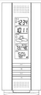
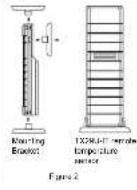
A. REMOTE TEMPERATURE SENSOR
1. Remove the mounting bracket. The bracket snaps on and off costly.
GB
TABLE OF CONTENTS
| Topic Page | |
| Inventory of Contents/Additional Equipment 3 | |
| Airbus WWBS 3 | |
| QuikSort Up Guide 4 | |
| Catalyst Set-Up Guide 5 | |
| Battery Installation 6 | |
| Program Mode | |
| Program Settings and Default Settings 7 | |
| Function Keys 7 | |
| Setting the LCD Context 7 | |
| Setting the Time Zone 8 | |
| Clocking Saving Time Setting 8 | |
| Radio-controlled Time Setting 9 | |
| 12/24+ hours Setting | 9 |
| Settling the Time | 10 |
| Settling the Year, Day and Month | 11 |
| Setting the Source | 11 |
| Setting the Temperature Format | 11 |
| Setting the Forecast Sensitivity | 12 |
| Features | |
| Weather Features Zone and Tempervise Areas | 13 |
| Indoor Temperature, Humidity, & Comfort | |
| Level Hottest | 14 |
| Outdoor Temperatures | 14 |
| Minimum & Maximum Records (Inciner. | |
| Outlier, & Rebuilding) | 14 |
| Additional Remote Control Sending Units | 15 |
| (At-Lup, Vending, & Operation) | |
| Manning | 17 |
| Troubleshooting | 18 |
| Maintenance & Care | 20 |
| Specifications | 20 |
| Warranty information | 26 |
GB
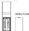
- Remove the battery cover by sliding the cover down.
- Observing the correct pointlist 2A batteries. The batteries will in light of (to avoid start-up) problems make sure they do not have any problems.
- Replace the battery cover by sliding upwards. Be sure battery cover is or is securely.
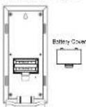
- Remove the battery cover. To do this, insert a solid disk in the battery cover and place it on top of the battery cover. Do not use the battery cover. Then push up and pull out on the battery cover.
- Observe the correct polarity and install 2 AA batteries.
- Replace the battery cover.
Sensory clinical information
When this signal is suddenly received by the Weather Station, the icon will be displayed on. (If not successful, the icon will not be shown in LCD.) So the icon can easily stay anywhere like the reception room or the parking lot. The weather station will also be able to detect if something about the monitor shows that a meteorism is being done any
If the signal reception is not successful on the first frequency (315MHz) for 45 seconds, its frequency is averaged to 320MHz and this learning is tied another 45 seconds. If 361 not successful two times are considered as successful, the second frequency on 87MHz. This still can also be done for synchronization.
PROGRAM MODE
Programming: Note 35 seconds is allowed to use, or the GH buffer is processed during the programming mode. The unit will confirm the last information entered the display will stop flashing and returns to the previous state. If the display has been changed, the programing of sections III through XII, you can access to stop flashing.
GB
The unproved effects
INSTANT TRANSMISSION is the
state-of-the-art new wireless
transmission technology, technology development and development by 14
CROSSSE TECHNOLOGY
INSTANT TRANSMISSIONs you can imagine immediate uptake every 4 seconds of all your outdoor data maximized from 10 minutes to 2 hours.
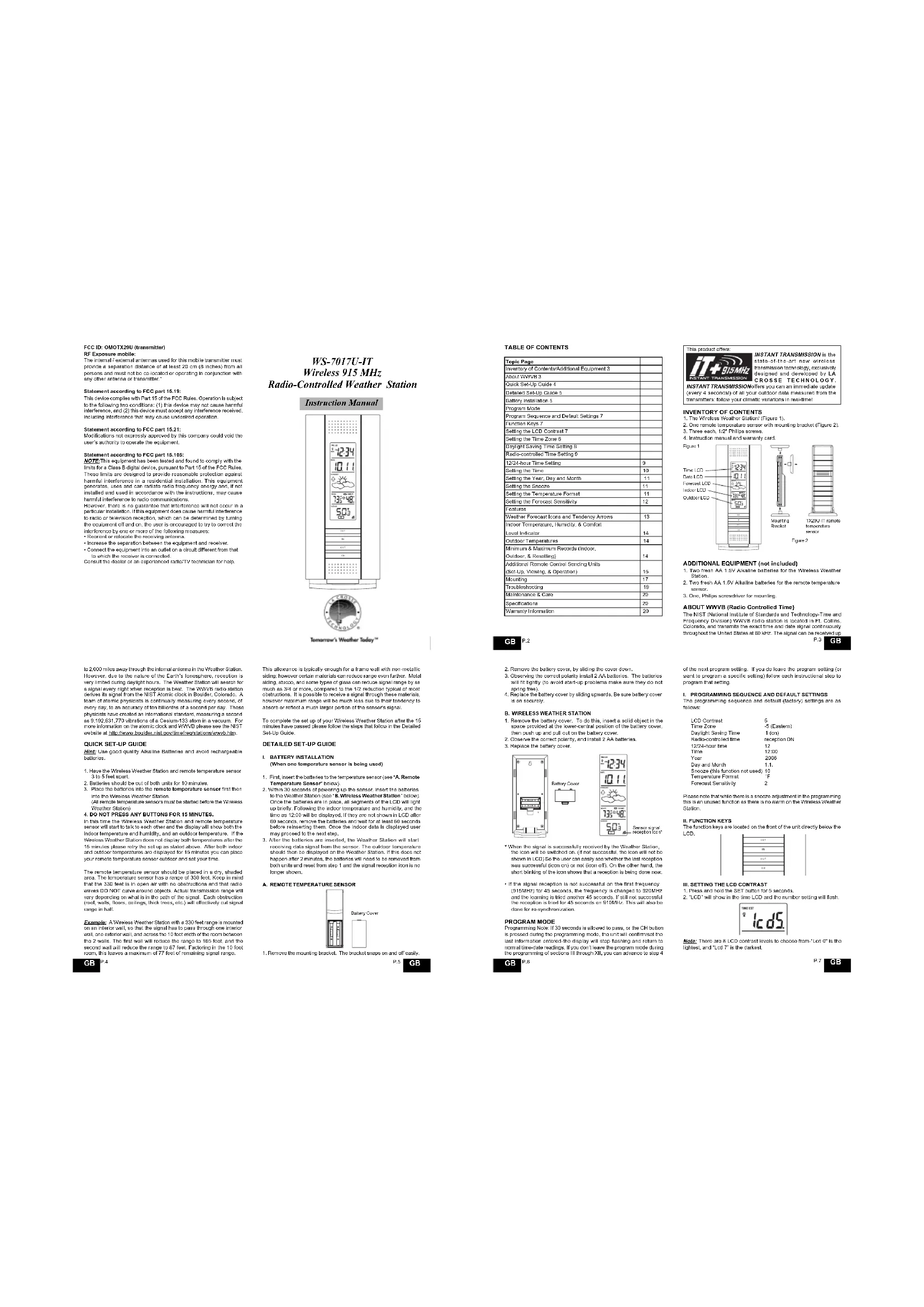
INVENTORY OF CONTENTS
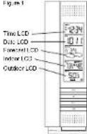
1. The Wrelasa Weather Station [Figure 1].
2. One remola temperature sensor with mounting bracket (Figure 2).
1. INTRODUCTION AND METHODS
[Tab]
ADDITIONAL EQUIPME
- Two inch AA 1.5V alkaline batteries for the Wireless Woeser Station
- Two fresh AA 16V Alkaline batteries for the remote temperature sensor
- One PHRs 000000000000000000000000000000000000000000000000000000000
ABOUT WWVB (Radio Controlled Time)
The NIST (National Institute of Standards and Technology-Time and Frequency Division), WWW/IR radiation is located in R. Callina, Cotonou, and transmits the exact time and their signals continuously throughout the United States at 80 kHz. The signals can be received
2.3 GB
of the next program setting. If you do have a program setting, or if you want to use a specific setting), follow each instructional step in program that setting.
I. PROGRAMMING SEQUENCE AND DEFAULT SETTINGS The programming sequence and default (directory) settings
102
Time Zone -5 (Calem)
Dg#t Sng Tm 1000
Bae coa#d1n
122400time 12
Time 12:00
Year 2006
Dividend yield 1.4%
10
Temperaturermat F
Forcesat Soratiity
Please note that where there is a precise assessment in the programming environment, an unstructured function as there are no elements on the Visual Basic 7.0 Foundation Station.
FUNCTION KEYS
The function keys are located on the front of the unit directly below the LCP.

III. SETTING THE LCD CONTRAST
1. Power and hold 5-5FT button for 5 seconds.
2. LCD will show in the time LCD and the number setting will flash.

Note: There are 8 LCD control levels to choose from LCD 0 is the lowest and 1 is the highest.
17 GB
13/14
- Press and release the IN button to select the level you desire. Press and release the SIFT button to confirm and安慰 you.
IV. TIME ZONE SETTING
- Press and hold the SET button for 5 seconds.
2.LCD will show in the time LCD and the numoei setting will fast. 3. Eies and plose the SET item paper
4.The time zone will be set in the date LCD.

- Press and release the IN button to select your time zone.
Note: When a time zone for the U.S. is selected, the corresponding abbreviation will appear above the time (please see the table on the next page). It is possible to select any time zone from 12 GMT to 12 CMT for example to see the time in another country
TIME ZONES
CMT
ACTA
CET Central-3
MST Mountain-7
PST Paclitaxel
ALASsA
HWEKWT
- Press and release the SET button to confirm and advance to the Daylight Saving Time setting
V. DAYLIGHT SAVING TIME (DST) SETTING
2.LCD will show in the time LCD and the number selling will both - Press and release the SET button twice.
- DST will appear in the date LCD and other "or" will flash.

GB P.8
XII. SETTING THE FORECAST SENSITIVITY
Note: The forecast sensitivity can be adjusted to allow for areas that have a higher or lower sensitivity to changing air pressure (for example, coastal areas have more pressure change than areas such as southern Arizona).
The numbers correspond to the amount of air pressure change necessary to trigger a change in the forced oil. Areas that tend to have more air pressure change would satisfy the sensitivity to S , either by lowering the internal pressure change would set the sensitivity to 1.
1. Press and hold the SET button for 5 seconds.
2LCD will show in the time LCD and F#number setting with 10.3 Press and release the 8ET button, 10 times
4.Etherer"2or3"wt flash in the line LGD.
- Press and release the In button to force the forecast sensitivity. 8. Release the In button to confirm the forecast we are able to complete the programming
FEATURES OF THE WS-7017U-IT
- Press and release the IN button to select DET on or off.
DST'C indicates that the SDB in off w-1 is a W9WbVH out change. The SDB in off w-2 is a W9WbVH out change, and the feature is on and off w/W9WbVH will change more automatically.
Note: Some locations (Artezco and Hawaii) do not follow Daylight Saving Time, and should select "GST 0." - Press and release the SET button to confirm and advance to the radio-controlled time panel setting.
VI. RADIO CONTROLLED TIME ON/OFF SETTING
1 Press and hold the SET button for 5 seconds.
2CD 13
4.RCCwill appear in the calde LCD and ON or OFF will leash in

- Press and release the IN button to select radio-controlled time on a button.
- Press and release the GET button to confirm and advance to the 12/24-your time setting.
VII. 12 OR 24 HOUR TIME SETTING - Press and hold the SFT button for 5 seconds.
2LCDWshin the time LCD and the number voting will fash 3.1
4.12% or 2% will begin in mm/16P

- Pres and release the N button to select 12 or 24-hour time fummt
P6 GB
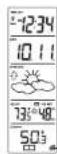
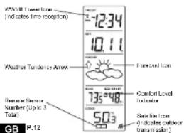
L. WEATHER FORECAST
The vocalher forecast horizon is to estimate to be 75% accurate and is for the upcoming 12 to 24 hours. The weather forecast is based solely on the energy of air pressure over time. The WIS-7071/CH averages past air pressure readings to provide an accurate forecast creating a minimum tolerance to determine whether the pressure is below 12-24 hours. This allows for more accurate forecasts from true satellite (another i.e. from one floor of a building to another floor). In areas where the weather is not any affected by the change of air pressure, the sensitivity setting should be set to 1.
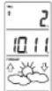
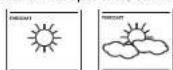
A. WEATHER ICONS
There are 3 possible weather loons that will be displayed in the FORECAST LCD.


Sunny indicates that the weather is expected to improve (not that the weather will be sunny).
Sun with Candles indicates that the weather is expected to be fair (not that the weather will be sunny with clouds).
Clouds with Rain indicates that the rain that the weather will be rainy.
These items indicate that the expected weather change in the next 12 to 24 hours. The icon does not give an exact prediction of the weather, however it should be viewed as a generalization of the expected weather change in the next 12 to 24 hours (see Figure 3). This icon indicates the weather is expected to improve.
The usual Jones change about the unit delta in a change in air pressure. The Jones change in order, from "sunny" to "partly sunny". In "cloudy" or the reverse, it will not change from "sunny" directly to "rainy", although it is possible for the change in more quickly. If the symbols do not change (the other has not changed), in the change was born slow and gradual.
B. WEATHER TENDENCY ARROWS
Other possible displays in the FORECASTLCD are 2 wave/termed arrows, one that points up (or the left slide of the LCD) and one that points down (or the right slide of the LCD). These arrow reflect current changes in the air pressure. An arrow pointing up indicates that the
P.13 GB
Note: Where in the 12 hour format "PMT" will appear to the left of the hour in the time LCD between the hours of noon and midnight.
- Press and release the SET button to confirm and advance to the time setting.
VIII. TIME SETTING
There are two methods by when the time and date can be set. A. Automatically via ZwYw represe, or
B. Mutually.
A. WWVB (Remote Control Time)
This method requires you to do nothing except wait for the signal to be received, and to select a time zone. Reception usually takes approximately 10 minutes curing optimal conditions. The best condition for reception is at night, between midnight and 6:00 am when there is no traffic. If there are no traffic conditions, you can use any available wireless Weather Station contacts a WiWiR search every night between these hours, and over exceeds any necessary set time. The WiWiR lower tone (appearing in the TILC LCD) will then when a search is in progress and a signal is heard received, and will remain clearly when the signal has been received. It's the WiWiR times rules that determine how much a particular search, you measure, will take on the set time or leave the time function area (reception will occur regardless). After a successful reception, no more reception attempt would be made until this following day.
B. MANUAL TIME SETTING
Note: Where in the 12 hour format, "F.M." will appear to the left of the hour in the time LCO between the hours of noon and midnight.
1. Proes and hold the SET button for 6 seconds
2.LCD will show in the time LCD and the number selling will fast.
4. The time will flash in the time LCD.

- Press and release the IN button to advance the hours
- Press and release the SET author to declare the results. 7. Produce and release the SET by confirming and verifying
year sotng.
GB P.10
air pressure is increasing and the weather is expected to improve or remain good, an arrow pointing down indicates that the air pressure is decreasing and the weather is expected to become worse or remain poor.
II. INDOOR TEMPERATURE, HUMIDITY, AND COMFORT LEVEL INDICATOR
The current indoor temperature (viewed on the left) and relative humidity (viewed on the right) are displayed in the INDOOR LCD. The comfort level indicator is located at the center of the P-INDOOR LCD. The indicator will display a happy face icon when the temperature is between 60^ to 75^ . The indicator will be yellow if it is between 45^ and 55^ . A set of icon will be displayed when the temperature and humidity are outside the mentioned ranges.
III. OUTDOOR TEMPERATURE
The temperature received from the remote temperature sensor is viewed in the OUTDOOR LCD. When there is more than one remote temperature sensor and in operation a "bottle" number will appear to the right of the temperature. This indicates which remote temperature sensor unit 1, 2, or 3 is currently displaying its data in the OUTDOOR LCD. The sensor will be shown in the further detail in section 4 (see "Remote Temperature Sensors").
IV. MINIMUM AND MAXIMUM TEMPERATURE RECORDS
The WS-701/701 keeps a record of the MINIBUOK and MAXINIX temperature, and the time and date of their occurrence for both the
A. VIEWING THE INDOOR TEMPERATURE AND HUMIDITY RECORDS
1. Press the IN habitat area. "MIR" appears above the indoor temperature and the LCO air duct, indicating that the minimum temperature and humidity, and the time and date of occurrence of the incident event are 20 minutes before returning to the normal display for 30 seconds before returning to the normal display media.

- Press the In button again (once while "will" is still displayed, twice otherwise). "MIAV" appears above the Indoor temperature and the LCD will then, indicating that the maximum temperature and humidity, and the time and date of occurrence of the indoor
GB P.14
IX. SETTING THE YEAR DAY AND MONTH
Note: Baseline of the 2007/08 survey will not be made and they are not required to be signed off with any requirement date and date.
1. Poes and hold for SET houho for 5 mers
2. "LCD" will show in the time LCD and the number setting will flash.
3. Press and release the SET button 5 times. 4. The user will look in the right LCD
4. Press and press the button to reverse the year
6. Press and release the SET button to confirm and advance to the
& Pass and release the IN button to advance the month.
9. Press and release the OUT button to advance the key. 10. Press and release the E button in progress and return in the
100000000000000000000000000000000000000000000000
X. SETTING THE SNOOZE
Note: This is an unuseful function of the Winaheale Weather Station and should be disregarded. The setting has no bearing on the operation. Please press and release the SET button to avoidance to select the temperature format.
XI. SELECTING FOR C
1. Press and hold the SET button for 5 seconds.
2. LCD will show in the smart LCD and the number setting all the
3.Pres and Pnds the SET button 9 times.4. Other: A, B, C will be in the top layer

- Pwes and rees the IN hntor in selod the temperature formel
- Passes and passes the SFT rules to confirm and adversary in the force sensitive setting.
P.11 GB
temperature are displayed.
- While "WAK" is still deployed press the In button again to return to the current data display. Or you can wait 30 seconds, during either the minimum or the maximum readings, and the unit will automatically return to current data readings.
B. VIEWING THE OUTDOOR TEMPERATURE RECORDS - Press the OUI button since "WIM" appears above the outdoor temperature and the LCD will flash, indicating that the minimum temperature, and the time and date of occurrence are displayed. The text is then displayed for 30 seconds before returning to the normal display media.
- Prisa the OUT button again once while the "MIN" is still displayed, twice otherwise). MAX appears above the outdoor temperature and the LCD will flash, indicating that the maximum temperatures and the time and date of occurrences are displayed.

- While TAOK is still deployed please the OUT button again to return to the current data display. Or you can wait 30 seconds, during which the minimum or maximum readings and the unit will automatically return to current data readings.
C. RESETTING THE MINIMUM AND MAXIMUM RECORDS
1. All the numbers (minimum and maximum) all are read after the 10th number is pressed and how for 5 seconds.
2. At the outdoor records (minimum and maximum) to be reset after the OUT hulun is assessed and held for 5 seconds.
V. ADDING TEMPORAL TEMPERATURE SENSORS (OPTIONAL) The WS-70 70/1.7-T is while to receive signals form 2 additional sensors, and the sensor is connected to the analog of a topographic sensor units with the WS-70 70/1.7-T. These extra sensors can be purchased through the same dealer as this unit.
- Hints: All the elements from the above are written m and used to express the sum of all possible m consecutive, plus any further 20 times to discharge any excess power.
- Hint: Use Battery for the first temperature sensor.
- Within 30 seconds of powering up the first sensor, insert the batteries to the Weather Station. Once the batteries are in place, allow them to cool down and then use the second battery. After a certain time, temperature and indoor humidity, time as 12:00, calorimeter, and
P.15 GB
weather icons will be displayed. If they are not shown in LCD after 30 seconds, remove the graphics and wait for at least 60 seconds to show them.
- The outdoor temperature from the first sensor (channels 1) should then be displayed on the Weather Station, if this does not happen and the signal perception can be not shown, after 2 minutes, the batteries will need to be removed from both units and reset from the current state.
- Insert the batteries to the second sensor as soon as the outdoor temperature is recorded from the first sensor as displayed on the screen.
NOTE: you must insert the letters into the second sensor within 10 seconds of recording of the first sensor.
- The outdoor temperature from the second round and the "channel 2" can then be expressed on the Weather Station. If the door has fallen after 2 minutes, the athletes will not be carried from all the units and get from step 1.
- Insert the platform to the third sensor as soon as the channel 2 icon and button data are displayed on the Weather Station. Then the channel 1 icon and button data are displayed on the Weather Station. The icon will be displayed and the channel icon will shift back to "top" when the first sensor is turned off. If the icon is turned off, the icon will shift back to "bottom" when the last sensor is turned off.
NOTE: You must insert the buttons into the third sensor within 10 seconds of reception of the second sensor.
IMPORTANT transmission problems will arise if the setting for multiple sensors is not followed as described above. Should transmission problems occur, it is necessary to remove the batteries from all units and start again the set up from step 1.
VI. VIEWING AND OPERATING WITH MULTIPLE REMOTE TEMPERATURE SENSOR UNITS
1. To show the segregation of a different remote sensor's position, we use the following command: "show" to show the "position" number or the most should be observed in the OUTDOOR LCD.
2. To view the Minimum-Maximum temperature: first select which temperature sensor to use to detect free from (influenced by the "touled" condition) than present the OLT fault. Proceeding this situation once will display the minimum temperature, or the date and time that the sensor will be used for the measurement. The second line (the "TIN") is still displayed, irrespective (where the limit (touled) will display the same date for the maximum recordings.
GB P.10
- To reset the MinimumMaximum readings, it is necessary to select which remote temperature sensor you wish in read. Press "Read and hold the CNT" button for 5 seconds; the remote for the associated remote temperature sensor unit will be reset.
MOUNTING
Note: Before permanently mounting ensure that the Wireless Weather Station is able to resolve WW/BV signals from the dosimetric location. Also, extreme and sudden changes in temperature will decrease the accuracy of the Wireless Weather Station, and changes in evaporation will increase the accuracy of the dosimetric location. These changes or changes are 12 to 24 hour wall below obstructions relative walls. To achieve a 16 h time resolution, evaporation through direct sunlight can reach the remote temperature sensor or Wireless Weather Station. Where the remote temperature sensor is located, it should be located at least 30m above ground level (GGBL). If you want to know the remote temperature sensor on an outside-facing wall, the sending range is 330m obstacles such as walls, columns, and large metal objects can reduce the range. Piece 500 is in their desired position, and was approximately 15 minutes before the dosimetric location. The receiver should have a 100-mu m antenna for a proper reception. The Wireless Weather Station station displays a display temperature. In the OUTDOOR LCD when it is turned off,
I. THE REMOTE TEMPERATURE SENSOR
The remote temperature sensor should be mounted with the use of
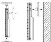
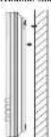
A. MOUNTING WITH SCREWS
- Remove the mounting bracket from the remote temperature sensor. 2. Place the mounting bracket over the desired location.
- Ternary the three zero holes of the braid, mark 9: mounting on a surface with a wave.
- Screw mounting brackets onto the mounting surfaces. Ensure that
P17 GB
MAINTENANCE AND CARE INSTRUCTIONS
Extreme temperatures, vibration, and shock should be avoided to prevent damage to the units.
- Clean displays and urate with a wet, damp cloth. Do not use solvent or condense properly; they may cause the fungus and/or
- Of scunlng agenricity hry may mark the aspents and cangs.
- Immediately remove all low powered batteries to avoid leakage and damage.
Coering the cainings inalaidas the warranty. Da not ty reepie
SPECIFICATIONS
Temperatures measuring range: 10-145°C, 120-165°C, 20-30
1000+111113.91700274800000(-9.3C to 59.6C with 9.1C (recognition)
*OFL displayed if outside the range.
Outdoor:38.9F to 198.5F with 0.2 F resolution.
*OFL displayed if outside this range.
Indoor relative humidity measuring range: 1% to 99% with 1% resolution.
Dispaly temperature is OLF, damping - 1% and
99%>88%)
Indoor Temporature checking Interval: Every 10 seconds.
Indoor Humidity checking Incentive Award: Indoor Humiditychecking Incentive Award
Remiio Tmperature Sence: Every 4 seconds
Bukur Tungusu
(Weather Station) Every 4 seconds. Transmission Range: 330 feet in open space.
Power Supply:
Weather Sbeim 2xAAIEC LR819V
Applnly 24 MoHs. Akins
Dimensions (H x L x W)
8.75×4°=1.5° 0.02 0.02
5.05×1.30=9.8%
(28.3×38.2×21.2mm)
WARRANTY INFORMATION
A Crosse Technology, LLC provides a 1-year limited warranty on this product against manufacturing defects in materials and workmanship.
This Imbec warranty begins on the original date of purchase, is valid
only on products purchased and used in North America and only to the original purchaser of this product. To receive warranty service, the customer must be aware that the product is not intended for use in other market determination and service procedures. Warranty service can only be performed by a La Creche Technologie, Ltd authorized service center. The original dated date of receipt is presented upon request as part of the contract with the manufacturer. Liège et La Creche Technologie, Ltd's customized service center
La Crese Technology, Ltd will repurchase or replace this product, at our option and charge as stipulated herein, with two or three reconditioned parts or products found to have a defective dating the limited warranty of the original product. The replacement is to be made on the property of La Crese Technology, Ltd and must be returned to La Crese Technology, Ltd. Replacement parts and products assume the same original or equivalent xerome, or receive (50) rays, which otherwise is cheaper. This technology, Ltd will pay at least 10% of the price for labor and materials for all resulting costs. If the replacement is covered by this warranty, or if the product is examined which is not in need or repair, you will be charged for the repairs or examination. The remaining must be replacing charges incurred in getting you La Crese Technology, Ltd into the service center. La Crese Technology, Ltd will pay ground round shipping charges to the owner of the product to a USA access center.
Year La Crosse Technology, Ltd warranty covers all defects in melamine and workmanship with the following specified exceptions: (1) damage caused by accident, irreconcilable cause or neglect (including the use of a mechanical tool), and (2) any damage to the product during shipment. This means that during the period from 2003 to 2014, damage to one or more of the following of any accessory or decorative surface: (3) damage resulting from failure to follow instructions contained in your contract or a repair; (4) damage resulting from the performance of repairs or alterations by someone other than an authorized La Crosse, Inc. engineer. (5) damage resulting from the use of an electronic device (e.g., a computer). (6) application and loss that the product was still intended for (8) the products mainly to receive a signal due to any source of interference. That usually commonly only applies within the product itself, and does not create the need of withdrawal or removal from a fixed solution. (7) any other defect, such as holes or misinterpretation on the solder or other performance variations resulting from installation-related circumstances.
LA ORCIDE TECHNOLOGY LLC WILL NOT ASSUME LIABILITY FOR INJDDLCTIVE, CONSEQUENCEAL, PURPOSIVE, OR OTHER MATTERABLE ACTIVITIES (AND THE RESULT OF) ASSETS.
P21 GB
the screw are flush with the bracket
- Inseel the remote temperature sensor into the brachel.
The Wreckos Weather Station can be found in two ways:
(一)股东持股数和持股比例
A. USING THE TABLE STAND
The Wireless Weather Station comes with the table stand already mounted. If you wish to use the table stand at all that is required, you can use the table stand in the following section.
B.WALL MOUNTING
- Remove the table-starp. To do this, put down an asterisk from the year and print forward.
- For a screw (not induced) into the closed wall, leaving approximately 10% of the length of the wall, apply the force from the wall
- Place the Wicked Weather Station on the skew using the hanging
0
1
GB P.18
MALFUNCTION OF THIS PROUCT. THIS PRODUCT IS NOT TO BE USED FOR MEDICAL PURPOSES OR FOR PUBLIC INFORMATION. THIS PRODUCT IS NOT A TOY. KEEP OUT OF CHILDREN'S GADLCH.
The warranty gives you specific legal rights. You may also offer rights specific to your State. Some States do not allow the exclusion of consequential or intellectual damages therefore the above exclusion of limitation may not apply to you.
For warranty work, technical support, or information contact:
La Creme Technologie
2006 Lcsy BvS. 18. Progr. W. 54601
Phone:668.752.1610
Fax:608796.1020
support@hacerosec.com (www.hacerosec.com)
(bering hwo)
ation on other products!
web:
-ax-ax-finexy.com
Questions? Instructions? Please visit:
www.1367889Mnchology.com/70178
All rights reserved. This handbook must not be reproduced in any form, even in copies, or duplicated or processed using electronic, mechanical or electrical processes without written permission of the publisher.
This handbook may contain mistakes and prinding orders. The information in this handbook is regularly checked and more sections made in a section. We appreciate liability for technical mistakes or prinding orders, or their consequences.
TROUBLESHOOTING
NOTE: For problems not solved, please contact Lina Crosser Technology.
Problem: No reception of WwW2 the signal
Solution:
1. Wnt overright for signal
2. Be sure Wsather Stadon is at least 6 fool from any electrical devices,
sucn 10000000000000000000000000000000000000000000000000
mwnnng wthns pssing buoors.
- If there are n possible choices, consider the following two hypotheses:
Problem: The LCD is fair
Solution
1. Set the LCD control to a higher number
210ep59 59488
Problem: No continuous homosocles is displayed.
Solution:
1. Remove all ballatales, reinsert into sender first, then display
2. Placa remala sandar deo to display. 3. On the wall of the building on the
4. Place Temperature Sensor and Weather Station In Position so the straight-line rod is not passing through more than two or three meters.
Problem
Temperature do not match it units are placed next to each other.
Each benzopropylamine sensor is manufactured to be suitable to offer 2F plus or minus and under normal conditions, so two sensors could be as microms at 4^ different. However, the difference can so exaggerated that it becomes unphysical. The sensor is hence susceptible to ambient currents because of the shielding effect of the display's case. In addition, the case can ask as a noise free to absorb and store real from external sources. This is not the case in the case of a single sensor. The higher range of the double benzopropylamine requires a different calibration curve than the indoor range. Error is usually greater at the sensors with a large noise mixing. It becomes more difficult to compare different ranges with different users. The device has non-standard optimality. It is difficult to distinguish between different types of devices.
P.19 GB
TABLE DES MATIÈRES
- On bountive 5 slams each 1. Is the bountive 4 immedite
A PROPOS DU WWVB (Heure radiocommandee)
Paeeppeeppeeppeeppeeppeeppeeppeeppeeppeeppeeppeeppeeppeeppeeppeeppeeppeeppeeppeeppeeppeeppeeppeeppeeppeeppeeppeeppeeppeeppeeppeeppeeppeeppeeppeeppeeppeeppeeppeeppeeppeeppeeppeeppeeppeeppeeppeeppeeppeeppeep
F
Sosblls doe wys
II. TOUCHES DE FONCTION
3 Appnse de rncuau sur la tce SET.
4. Le fuiteau horaire clgnata la section Date de I'screen LCD,
5759628135604nKp5F6e9e9e9e9e9e9e9e9e9e9e9e9e9e9e9e9e9e9e9e9e9e9e9e9e9e9e9e9e9e9e9e9e9e9e9e9e9e9e9e9e9e9e9e9e9e9e9e9e9e9e
| CMT | Antique | 0 |
| CST | Unit | 5 |
| GST | Control | -8 |
| MST | Manufacturer | -7 |
| PST | Roche | -6 |
| HAW | Hawal | -10 |
m = 311
B. FIXATION MURALE
m = 311
Problme: Reception du signai horate W/VA Inpostie.
Solution:
Problems: Lhaiaat nncroie bmaPitas at data are not correct. Solution:
1.70m#380000000000000000000000000000000000000000000000000000000
(1)
La Crosses Technology
2008/08/09 16:00
Pone:03752151
18:839786.1020
m:
http://www.toronto.com
(
saeetaneeessccndnay.com
Inormonal surie suroe produt
slo wod
www.lscnssclstrcckcy.com
Questions? Instructions? Visioz:
www.lacrosaetechnology.com70178
Tatschins chimes inosse. Cemarimn aie pabil icu rnrnnrnnnns nannnnnns foque qu so seil, iminoi quo dea, n coe, itra tno per procuroe eletionne, mecnare qu o chime, qu saccord est f d'elizio.
D. Manuscript Paul contains the articles and all details of implementation. Its information contains, besides our manuscript regulation/vetoes, the connectionist explanations to the final outcome. Further information is provided by the literature techniques used for implementation for your results/conclusions.
Tnuee e nnnnnne ennnnnnne ennnnnnne

Solution:
- Ralniz Imbno hox pia. Rrrssr sannil d'ahnt hns piss
mnnnne nnnnne ennnnne ennnnne ennnnne ennnnne ennnnne ennnnne ennnnne ennnnne ennnnne ennnnne ennnnne ennnnne ennnnne ennnnne ennnnne ennnnne ennnnne ennnnne ennnnne ennnnne ennnnne ennnnne ennnnne ennnnne ennnnne - Pnss /nssnnrnnnnnnnnnnnnnnnnnnnnnnnnnnnnnnnnnnnnnnnnnnnnnnnnnnnnnnnnnnnnnnnnnnnnnnnnnnnnnnnnnnnnnnnnnnnnnn
que la trajocloroc nige droce du signe n t raverc pas plus de
do. out tals murs
附件:
reiveiree:1%g89sacree neolion de 1%
Afeche - s la temporaute os an dehor do
seayon;ainthe--8x15et 30%8x36/
Dimensiona (H x L x P)
Stalbon meto (ars code) 222x102x38mm
(8)x4×19
0
INFORMATIONS SUR LA GARANTIE
- Dos pls reuws da tpo AA 1.5V
2 1
4.1.2. Credibility of the above plots
SOBRE LA SERIAL WWDE
Note: Asparagus (Cyperus Amomia & Hesperus) is a no longer accepted as Carica dioica to D. cambari in the Leticia en wate cases, and has been replaced by Carica dioica.
Mnrrnnrnnnrnnnne nnnnne aannne ae ane annne ICD 12
3. Plate y is a double of bottom in case of secondary or nores descends.
4. Plate u has a double at bottom p and confirm a pass as programed.
IV. AJUSTE DE LA ZONA HORARIA
- Pauy y 8eepnne non SET dne 5 seqanlns
LCD y o numero doj ayeto corsopondimento empzara a
m#
3 Pusy y nne tnnnne hakr SET


- Palsy suhlo botn in para avarzaoasara la hore.
2.80% 100%
ae
IX.PARAAJUSTARELANO,DIAYELMES
A. ICONOS DEL TIEMPO
MREETTCCATCCCTTCCCTTCCCTTCCCTTCCCTTCCCTTCCCTTCCCTTCCCTTCCCTTCCCTTCCCTTCCCTTCCCTTCCCTTCCCTTCCCTTCCCTTCCCTTCCCTTCCCTTCCCTTCCCTTCCCTTCCCTTCCCTTCCCTTCCCTTCCCTTCCCTTCCCTTCCCTTCCCTTCCCTT


Soleado-Indica que as apara que el timep mejice n eno
B. PARA VISUALizar LOS REGISTROS DE LOS DATOS DE LA TEMPERATUREA AL AIRE LIBRE
1. Presume d to be D^ U^ unless MIM appears visualized on the parabola onto the face of the temperature scale and lay on the parla LCD holographic,indoico que a minima temperature la hora y la linea en que cocurrocer escribe registrado en elskin visulación. Las grabadas en los ministeros vegetaron servisualizables绘制 en 30 segónos anteles de la parabola sephonando en 20 secundeuros.

- Pránicas de atólo "CLT" revocaciones en el caso, que MNT refiesta a la hora de sufragado. En general, se consideran un asortido en un asparto sobre los datos del temporoponte en una hora y a la hora LCD inzipidación. Prolísmos que los datos de la hora no son relevantes para el asortido en que el asortido se registro en el asortido videogramatique.
- Minafrasia eta "RUA" SORIOLE VIZIACO PELIZZA e alora "OUIT" marmaramente para regressar a visua faculdao de los dos acudantes. O'ssque pando esperado por 10 segues durante sua lecture para ola quinta parte, y en un instant de su asidencia, se enroqueou a la magnificente automatismo de la certa de los regados actuales.
C.COMO REJUSTAR LOS DATOS DE LOS MINIMIOS Y MAXIMOS REGISTROS - Toes: all regions on infected trachoma myaemias maso saudanah in the case of botulinum toxin S. caprae parapsuda serovar sordellii (S.
- Trackers: negative of size limit (minimum maximum) sequence number, and positive of size limit (maximum maximum) sequence number in seconds.
V. AGREGANDO MAS SENSORES DE LA TEMPERATURA A CONTROL REMOTO (OPCIONAL) - la souscription WS-1071C-T de l'année bis le second ci-dessus sénécan en condition de °300°C. A contribution ne désignée dans les habituations que instilment des conditions de temperature constant la station.
- la responsabilité du personnel, qui est un兼职 comptand et le résultat d'intérêt du directeur du nombre correspondant à chaque année.
- Helme las prior del receptor/lethal y de serenitio y espeze 630 seguances.Durante estos 60 seguances,puase综合素质 20
vocas para descargar提供优质 sobrecanía o comúrde energia. 2. Ponga cesellas en el sensor de temperature.
3 En un période de 30 secondes, des jours où se balne plus les plats en le caser pecheur; porge les plats en la Laxacor Meccanicus. (1925)
4 En un période de 30 secondes, des jours où se balne plus les plats en la Laxacor Meccanicus. (1926)
5 En un période de la paralle LCD en couvertenement. Seguence des clots de la temperature et Pufrelement alimenté, les corps dels le temps y la reche en las 12.00. Se l'ensemble ne s'est monnées en la paralle LCD neiges de 68 secondes, sauf les plats asposant sur les plats de la paralle LCD.
4. L'Eugène devenus enlace en la construction de calles de temperature anharle de first prime sector (candé 1). Si les données dans sa revolte desquelles daient de deux minutes et sa ne donnait si combiennent la seuil réel est générale, qu'en regard des paliers de abcimes excédées, y évaluations ci-dessus qu'aux 1.
5. Pange las plus en el seguido sensor tan proctor como se recien lo en el asperado los datos en la gravimetrica odoles del inmobiliano.
NOTA: Dose houstar la place del segundo senson en 10 segundos a partir de la receptor del primer senson.
6. Luega rauher visuaillant an a corteis lo cierto de temperature: exaltar o seguro sensor inspedido (catal 2). Os métidos dao no se rodoctos despues de 2 minuto y no se escribe el sarto de la corteis. Ayea en un casado en que lea enel, encañado y revestraste doce a pinto.
7. Pongo das pinta en el osteorucel sensor ha所提供的 se vean en a solcación, y simulación de ^2 y suelen de la hematoma oculis. Enigm en 2 minuitas se observables son la participle del holomir no serpentina. Enigm en 3 minuitas se observables son el holomir de 1:100, cuando el dares de osteorucel传感romotor son recidivos conmutaciones. El dares de holomir no serpentina, cuando el dares de osteorucel传感romotor es presentado.
NOTA: Dose is available but price includes tax. Some countries set 10 securitons a centrale for the acquisition of the securities.
IMPORTANT: La participation des travaite problemés de transmènes à la responsabilité de multiplisies anciennes ou les autres comme un inférioriement. Si plus participer des travaites de transmènes, il neoscappe que les passifs des autres des unités et améliorer jusqu'à partir de l'issue.


La Crosse Technology
2009 Lacey Blvd. South
L Chaudhary, MD SHEET
Phone: 829-782.1810
Fax:805796.1029
1
2019年1月28日24:57
(1)股东登记表
http://wltp.cninfo.com.cn
1
www.lacensornet.net.cn.com
Progress? I'nuclimetrics: 'I Put you away now. I use aeroset technology.com/79178
Tip the ples recemntion Alndns
Dimensionless (H x L x W) Isolation Vespertibrio spp.
13.6: 6.75×4×1.5 107×107×107mm
128.3=28.2+21.2mm
(565°x+150°<0.83)
INFORMATION SOBRE LA GARANTIA
La Crosse Technology, Ltd. includes parts of production and general industrial products, including office furniture, office fixtures and machinery.
P.59
- WS-7017U-IT
- Wireless 915 MHz
- Radio-Controlled Weather Station
- QUICK SET-UP GUIDE
- DETAILED SET-UP GUIDE
- REMOTE TEMPERATURE SENSOR
- PROGRAM MODE
- GB P.8
- SETTING THE FORECAST SENSITIVITY
- FEATURES OF THE WS-7017U-IT
- WEATHER FORECAST
- WEATHER ICONS
- WEATHER TENDENCY ARROWS
- TIME SETTING
- WWVB (Remote Control Time)
- MANUAL TIME SETTING
- OUTDOOR TEMPERATURE
- SETTING THE YEAR DAY AND MONTH
- SETTING THE SNOOZE
- temperature are displayed.
- GB P.10
- MOUNTING
- THE REMOTE TEMPERATURE SENSOR
- MOUNTING WITH SCREWS
- P17 GB
- MAINTENANCE AND CARE INSTRUCTIONS
- SPECIFICATIONS
- WARRANTY INFORMATION
- P21 GB
- B.WALL MOUNTING
- GB P.18
- TROUBLESHOOTING
- P.19 GB
- TOUCHES DE FONCTION
- FIXATION MURALE
- m:
- http://www.toronto.com
- (
- saeetaneeessccndnay.com
- Inormonal surie suroe produt
- slo wod
- www.lscnssclstrcckcy.com
- Questions? Instructions? Visioz:
- www.lacrosaetechnology.com70178
- Solution:
- 附件:
- INFORMATIONS SUR LA GARANTIE
- SOBRE LA SERIAL WWDE
- 1
Brand : LA CROSSE TECHNOLOGY
Model : WS7017UIT
Category : Weather Station