
DRA-685 - Audio Amplifier DENON - Free user manual and instructions
Find the device manual for free DRA-685 DENON in PDF.
| Product Type | FM/AM Stereo Receiver Amplifier |
| Dimensions (W x H x D) | 434 x 171 x 416 mm |
| Weight | 10.0 kg |
| Power Supply | AC 120 V, 60 Hz |
| Power Consumption | 3.4 A |
| Rated Output Power | 100 W + 100 W (8 Ω, 20 Hz-20 kHz, 0.05% THD) |
| Speaker Impedance | A or B: 4-16 Ω; A+B: 8-16 Ω |
| Audio Inputs | Phono (MM), CD, Tuner, DVD/VDP, VCR, V.AUX, Tape |
| Audio Outputs | Preamp (PRE OUT), Speakers A/B, Multi-source, Headphones |
| Video Inputs/Outputs | Composite, 1 Vp-p / 75 Ω |
| FM Tuning Range | 87.5 MHz – 107.9 MHz |
| FM Sensitivity (usable) | 1.4 μV (14.2 dBf) |
| AM Tuning Range | 520 kHz – 1710 kHz |
| AM Sensitivity | 18 μV |
| Signal-to-Noise Ratio (FM mono) | 80 dB (IHF-A) |
| Total Harmonic Distortion (FM mono) | 0.15% (1 kHz) |
| Main Functions | Multi-source, RC-872/RC-873 remote controls, station presets, speaker A/B switching, loudness control (LOUDNESS) |
| Maintenance and Cleaning | Unplug the unit before cleaning; use a dry cloth; do not use solvents |
| Safety | Do not block ventilation openings; do not expose to moisture; disconnect during thunderstorms or prolonged absence |
| Spare Parts and Repairability | Contact an authorized DENON service center; no user-serviceable parts |
| General Information | SLDC (Signal Level Divided Construction) design for improved signal purity |
Frequently Asked Questions - DRA-685 DENON
User questions about DRA-685 DENON
0 question about this device. Answer the ones you know or ask your own.
Ask a new question about this device
Download the instructions for your Audio Amplifier in PDF format for free! Find your manual DRA-685 - DENON and take your electronic device back in hand. On this page are published all the documents necessary for the use of your device. DRA-685 by DENON.
USER MANUAL DRA-685 DENON
AM-FM STEREO RECEIVER
DRA-685
OPERATING INSTRUCTIONS
MODE D'EMPLOI
FOR ENGLISH READERS
PAGE 2\~ PAGE 29
POUR LES LECTEURS FRANCAIS PAGE 2,30\~ PAGE 55
We greatly appreciate your purchase of this unit.
To be sure you take maximum advantage of all the features this unit has to offer, read these instructions carefully and use the set properly. Be sure to keep this manual for future reference should any questions or problems arise.
"SERIAL NO.
PLEASE RECORD UNIT SERIAL NUMBER ATTACHED TO THE REAR OF THE CABINET FOR FUTURE REFERENCE"
The lightning flash with arrowhead symbol, within an equilateral triangle, is intended to alert the user to the presence of uninsulated "dangerous voltage" within the product's enclosure that may be of sufficient magnitude to constitute a risk of electric shock to persons.

The exclamation point within an equilateral triangle is intended to alert the user to the presence of important operating and maintenance (servicing) instructions in the literature accompanying the appliance.
WARNING: TO REDUCE THE RISK OF FIRE OR ELECTRIC SHOCK, DO NOT EXPOSE THIS APPLIANCE TO RAIN OR MOISTURE.
CAUTION
TO PREVENT ELECTRIC SHOCK, MATCH WIDE BLADE OF PLUG TO WIDE SLOT, FULLY INSERT.
ATTENTION
POUR ÉVITER LES CHOCS ÉLECTRIQUES, INTERODUIRE LA LAME LA PLUS LARGE DE LA FICHE DANS LA BORNE CORRESPONDANTE DE LA PRESE ET POUSSER JUSQU' AU FOND.
This device complies with Part 15 of the FCC Rules. Operation is subject to the following two conditions: (1) This device may not cause harmful interference, and (2) this device must accept any interference received, including interference that may cause undesired operation.
This Class B digital apparatus meets all requirements of the Canadian Interference-Caising Equipment Regulations.
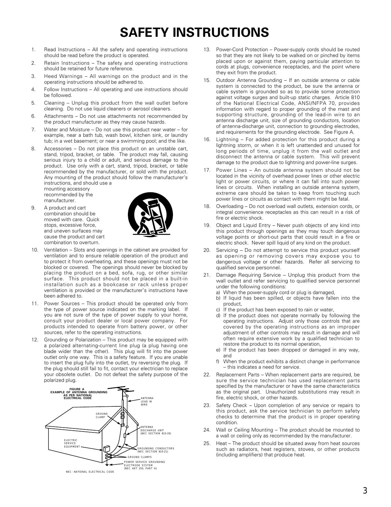
- Read Instructions - All the safety and operating instructions should be read before the product is operated.
- Retain Instructions - The safety and operating instructions should be retained for future reference.
- HeedWarnings - All warnings on the product and in the operating instructions should be adhered to.
- Follow Instructions - All operating and use instructions should be followed.
- Cleaning - Unplug this product from the wall outlet before cleaning. Do not use liquid cleaners or aerosol cleaners.
- Attachments - Do not use attachments not recommended by the product manufacturer as they may cause hazards.
- Water and Moisture - Do not use this product near water - for example, near a bath tub, wash bowl, kitchen sink, or laundry tub; in a wet basement; or near a swimming pool; and the like.
- Accessories - Do not place this product on an unstable cart, stand, tripod, bracket, or table. The product may fall, causing serious injury to a child or adult, and serious damage to the product. Use only with a cart, stand, tripod, bracket, or table recommended by the manufacturer, or sold with the product. Any mounting of the product should follow the manufacturer's instructions, and should use a
mounting accessory recommended by the manufacturer.
- A product and cart combination should be moved with care. Quick stops, excessive force, and uneven surfaces may cause the product and cart combination to overturn.

- Ventilation – Slots and openings in the cabinet are provided for ventilation and to ensure reliable operation of the product and to protect it from overheating, and these openings must not be blocked or covered. The openings should never be blocked by placing the product on a bed, sofa, rug, or other similar surface. This product should not be placed in a built-in installation such as a bookcase or rack unless proper ventilation is provided or the manufacturer's instructions have been adhered to.
- Power Sources - This product should be operated only from the type of power source indicated on the marking label. If you are not sure of the type of power supply to your home, consult your product dealer or local power company. For products intended to operate from battery power, or other sources, refer to the operating instructions.
- Grounding or Polarization - This product may be equipped with a polarized alternating-current line plug (a plug having one blade wider than the other). This plug will fit into the power outlet only one way. This is a safety feature. If you are unable to insert the plug fully into the outlet, try reversing the plug. If the plug should still fail to fit, contact your electrician to replace your obsolete outlet. Do not defeat the safety purpose of the polarized plug.
NEC-NATIONAL ELECTRICAL CODE
- Power-Cord Protection - Power-supply cords should be routed so that they are not likely to be walked on or pinched by items placed upon or against them, paying particular attention to cords at plugs, convenience receptacles, and the point where they exit from the product.
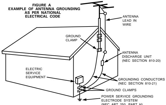
- Outdoor Antenna Grounding - If an outside antenna or cable system is connected to the product, be sure the antenna or cable system is grounded so as to provide some protection against voltage surges and built-up static charges. Article 810 of the National Electrical Code, ANSI/NFPA 70, provides information with regard to proper grounding of the mast and supporting structure, grounding of the lead-in wire to an antenna discharge unit, size of grounding conductors, location of antenna-discharge unit, connection to grounding electrodes, and requirements for the grounding electrode. See Figure A.
- Lightning – For added protection for this product during a lightning storm, or when it is left unattended and unused for long periods of time, unplug it from the wall outlet and disconnect the antenna or cable system. This will prevent damage to the product due to lightning and power-line surges.
- Power Lines - An outside antenna system should not be located in the vicinity of overhead power lines or other electric light or power circuits, or where it can fall into such power lines or circuits. When installing an outside antenna system, extreme care should be taken to keep from touching such power lines or circuits as contact with them might be fatal.
- Overloading – Do not overload wall outlets, extension cords, or integral convenience receptacles as this can result in a risk of fire or electric shock.
- Object and Liquid Entry – Never push objects of any kind into this product through openings as they may touch dangerous voltage points or short-out parts that could result in a fire or electric shock. Never spill liquid of any kind on the product.
- Servicing - Do not attempt to service this product yourself as opening or removing covers may expose you to dangerous voltage or other hazards. Refer all servicing to qualified service personnel.
- Damage Requiring Service – Unplug this product from the wall outlet and refer servicing to qualified service personnel under the following conditions:
a) When the power-supply cord or plug is damaged,
b) If liquid has been spilled, or objects have fallen into the product,
c) If the product has been exposed to rain or water,
d) If the product does not operate normally by following the operating instructions. Adjust only those controls that are covered by the operating instructions as an improper adjustment of other controls may result in damage and will often require extensive work by a qualified technician to restore the product to its normal operation,
e) If the product has been dropped or damaged in any way, and
f) When the product exhibits a distinct change in performance – this indicates a need for service.
- Replacement Parts - When replacement parts are required, be sure the service technician has used replacement parts specified by the manufacturer or have the same characteristics as the original part. Unauthorized substitutions may result in fire, electric shock, or other hazards.
- Safety Check - Upon completion of any service or repairs to this product, ask the service technician to perform safety checks to determine that the product is in proper operating condition.
- Wall or Ceiling Mounting - The product should be mounted to a wall or ceiling only as recommended by the manufacturer.
- Heat - The product should be situated away from heat sources such as radiators, heat registers, stoves, or other products (including amplifiers) that produce heat.
INTRODUCTION
Thank you for choosing the DENON AM-FM Stereo receiver. This remarkable component has been engineered to provide outstanding high fidelity reproduction of your favorite music sources.
As this product is provided with an immense array of features, we recommend that before you begin hookup and operation that you review the contents of this manual before proceeding.
TABLE OF CONTENTS
1 Before Using 4
2 Cautions on Installation 5
3 Cautions on Handling. 5
4 Features 5
5 Connections 6~10
6 Part Names and Functions 10, 11
Remote Control Unit. 12~17
8 Operations 17~23
9 Listening to the Radio 24~26
10 Initialization of the Microprocessor 27
[11] Last function memory 27
12 Troubleshooting 28
13 Specifications 29
■ ACCESSORIES
Check that the following parts are included in addition to the main unit:
① Operating instructions 1
② Warranty 1
③ Service station list 1
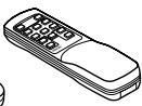
④ Remote control unit (RC-872)
(RC-873)
④
(RC-872)
(RC-873)
5
⑥
⑦
1 BEFORE USING
Pay attention to the following before using this unit:
- Moving the set
To prevent short circuits or damaged wires in the connection cords, always unplug the power cord and disconnect the connection cords between all other audio components when moving the set.
- Before turning the power operation switch on
Check once again that all connections are proper and that there are not problems with the connection cords. Always set the power operation switch to the standby position before connecting and disconnecting connection cords.
- Store this instructions in a safe place.
After reading, store this instructions along with the warranty in a safe place.
- Note that the illustrations in this instructions may differ from the actual set for explanation purposes.
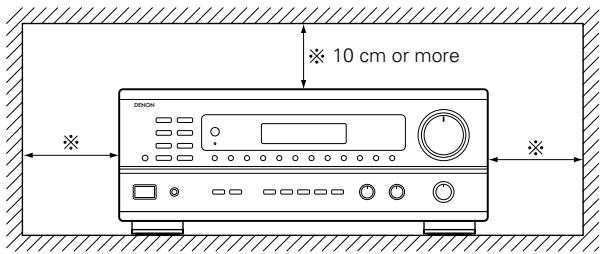
2 CAUTIONS ON INSTALLATION
Noise or disturbance of the picture may be generated if this unit or any other electronic equipment using microprocessors is used near a tuner or TV.
If this happens, take the following steps:
Install this unit as far as possible from the tuner or TV.
- Set the antenna wires from the tuner or TV away from this unit's power cord and input/output connection cords.
- Noise or disturbance tends to occur particularly when using indoor antennas or 300 / ohms feeder wires. We recommend using outdoor antennas and 75 / ohms coaxial cables.
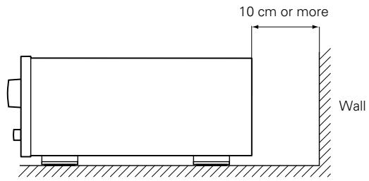
For heat dispersal, leave at least 10cm of space between the top, back and sides of this unit and the wall or other components.
3 CAUTIONS ON HANDLING
- Switching the input function when input jacks are not connected
A clicking noise may be produced if the input function is switched when nothing is connected to the input jacks. If this happens, either turn down the VOLUME control or connect components to the input jacks.
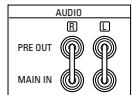
- Muting of PRE OUT jacks
The PRE OUT jacks include a muting circuit. Because of this, the output signals are greatly reduced for several seconds after the power operation switch is turned on.
If the volume is turned up during this time, the output will be very high after the muting circuit stops functioning. Always wait until the muting circuit turns off before adjusting the volume.
4 FEATURES
1. Multi Room Music Entertainment System
Multi Source Function:
This unit's Multi Source function lets you select different audio or video sources for viewing or listening. Different sources can thus be enjoyed in the main room and the subroom simultaneously. This novel feature gives you considerable flexibility when setting up and enjoying your system with the this unit. The output level, adjustable by the remote commander, is as much as 1V, enough to operate the optional power amplifier placed in a subroom.
2. Powerful, Versatile Amplifier
High-Quality Power Amplifier:
High-speed, high-power transistors employed in a rational circuit configuration reflect DENON'S advanced amplifier technology and ensure a very hefty, clean power output.
3. Signal Level Divided Construction (SLDC)
The circuits handling low-level and high-level signals have been divided into separate blocks to ensure that influences from these signals on each other are held to an absolute minimum. This chassis design in the this unit is called the Signal Level Divided Construction (SLDC). Signals for output are cleaner than before, allowing them to be reproduced with even greater fidelity and clarity.
- Whenever the power operation switch is in the STANDBY state, the apparatus is still connected on some AC line voltages.
Please be sure to unplug the cord when you leave home for, say, a vacation.
4. Remote Control Functions
- Remote Control unit with pre-memory function (RC-872):
This unit comes with a remote control unit equipped with a pre-memory function. The remote control command codes for DENON remote controllable AV components as well as for DVD players, video decks, TVs, etc., of other major manufacturers are prestored in the memory.
- Multi Source Remote Control Unit (RC-873):
This unit comes with the Multi Source Remote Control Unit, which operates the Multi Source Output and commands the receiver to select the function, recalling preset stations, and adjust the volume level from a subroom.
5 CONNECTIONS
- Do not plug in the power cord until all connections have been completed.
- Be sure to connect the left and right channels properly (left with left, right with right).
- Insert the plugs securely. Incomplete connections will result in the generation of noise.
-
Use the AC OUTLETS for audio equipment only. Do not use them for hair driers, etc.
-
Note that binding pin plug cords together with power cords or placing them near a power transformer will result in generating hum or other noise.
- If hum or other noise is produced when the ground wire is connected, disconnect it.
- Noise or humming may be generated if a connected component is used independently without turning the power of this unit on. If this happens, turn on the power of the this unit.
Connecting the audio components
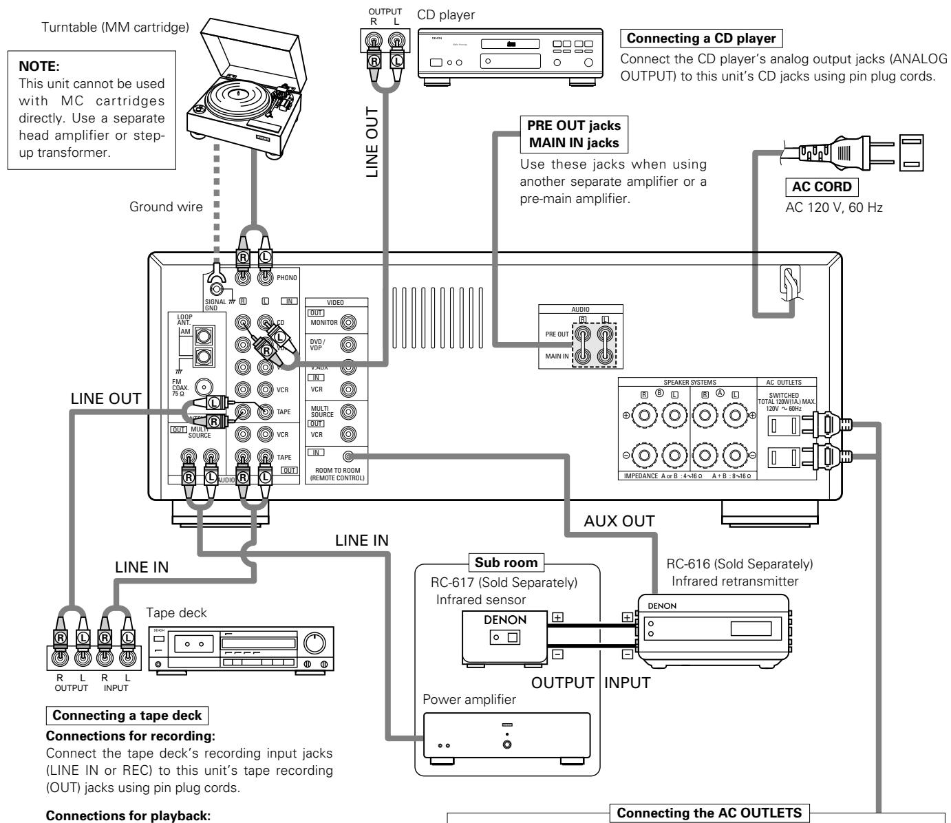
Connections for playback:
Connect the tape deck's playback output jacks (LINE OUT or PB) to this unit's tape playback (IN) jacks using pin plug cords.
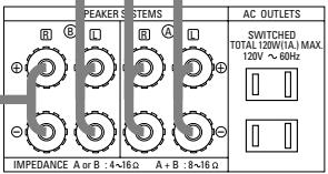
AC OUTLETS
- SWITCHED
(total capacity - 120 W (1 A.)
The power to this outlet is turned on and off in conjunction with the POWER operation switch on the main unit, and when the power is switched between on and standby from the remote control unit.
No power is supplied from these outlets when this unit's power is at standby. Never connect equipment whose total capacity is above 120 W (1 A.)
NOTE:
Use the AC OUTLETS for audio equipment only. Do not use them for hair driers, etc.
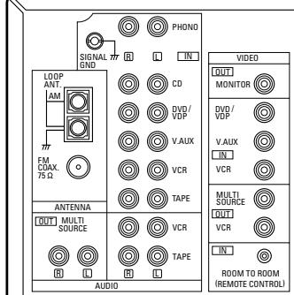
Connecting the video equipments
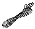
To connect the video signal, connect using a 75 Ω/ohms video signal cable cord. Using an improper cable can result in a drop in sound quality.
- When making connections, also refer to the operating instructions of the other components.
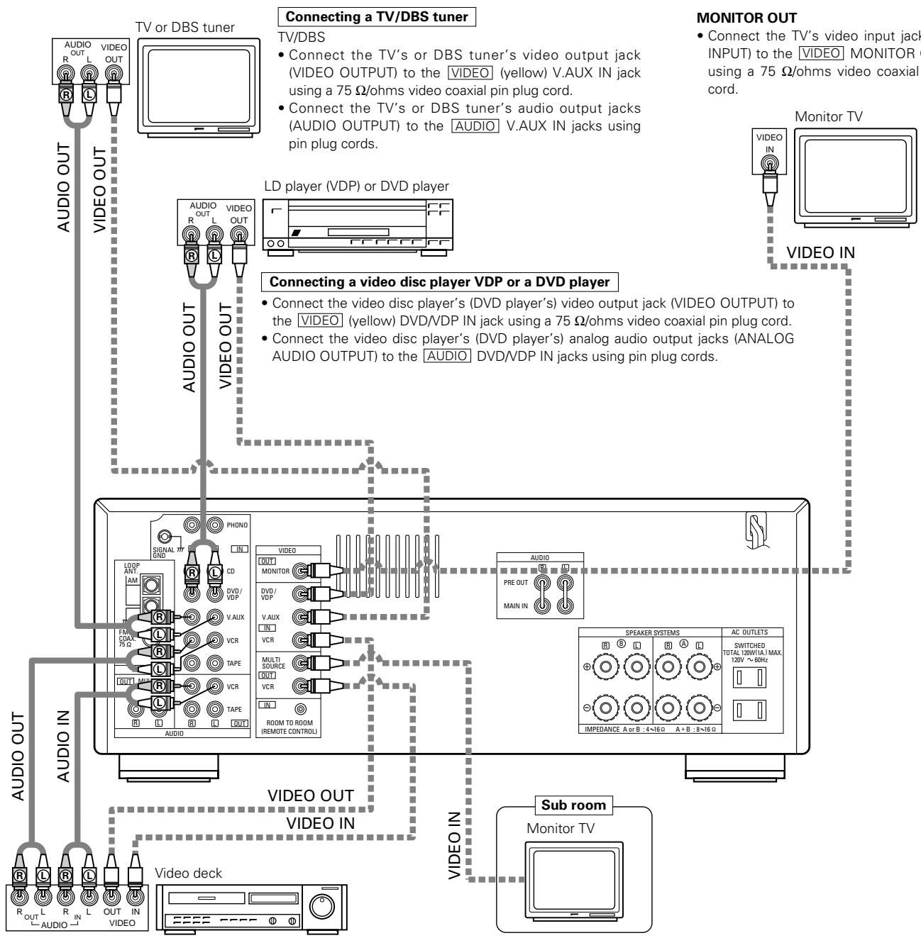
Connecting a video decks
Video input/output connections:
- Connect the video deck's video output jack (VIDEO OUT) to the [VIDEO] (yellow) VCR IN jack, and the video deck's video input jack (VIDEO IN) to the [VIDEO] (yellow) VCR OUT jack using 75 Ω/ohms video coaxial pin plug cords.
Connecting the audio output jacks
- Connect the video deck audio output jacks (AUDIO OUT) to the AUDIO VCR IN jacks, and the video deck's audio input jacks (AUDIO IN) to the AUDIO VCR OUT jacks using pin plug cords.
Connecting the antenna terminals
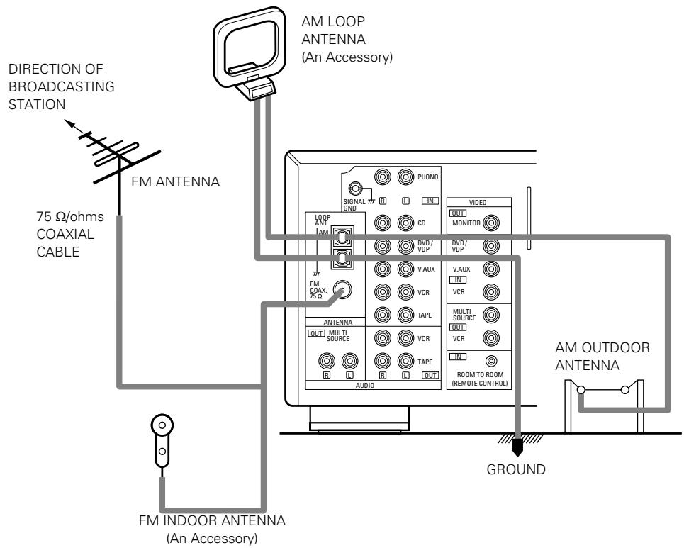
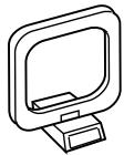
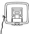
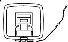
AM loop antenna assembly


Connect to the AM antenna terminals.


a. With the antenna on top any stable surface
Remove the vinyl tie and take out the connection line.
Bend in the reverse direction.
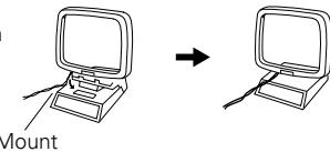
b. With the antenna attach to a wall.
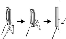
Instillation hole Mount on wall, etc.
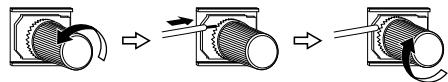
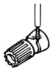
Connection of AM antennas
-
Loosen by turning counterclockwise.
-
Insert the cord.
-
Tighten by turning clockwise.
Note to CATV system installer:
This reminder is provided to call the CATV system installer's attention to Article 820-40 of the NEC which provides guidelines for proper grounding and, in particular, specifies that the cable ground shall be connected to the grounding system of the building, as close to the point of cable entry as practical.
NOTES:
- Do not connect two FM antennas simultaneously.
- Even if an external AM antenna is used, do not disconnect AM loop antenna.
- Make sure AM loop antenna lead terminals do not touch metal parts of the panel.
Speaker system connections
- Connect the speaker terminals with the speakers making sure that like polarities are matched (⊕ with ⊕, ⊙ with ⊙). Mismatching of polarities will result in weak central sound, unclear orientation of the various instruments, and the sense of direction of the stereo being impaired.
- When making connections, take care that none of the individual conductors of the speaker cord come in contact with adjacent terminals, with other speaker cord conductors, or with the rear panel.
NOTE:
NEVER touch the speaker terminals when the power is on.
Doing so could result in electric shocks.
Speaker Impedance
- When speaker systems A and B are use separately, speakers with an impedance of 4 to 16/ohms can be connected for use as speakers.
- Be careful when using two pairs of speakers (A + B) at the same time, since use of speakers with an impedance of 8 to 16/ohms .
- The protector circuit may be activated if the set is played for long periods of time at high volumes when speakers with an impedance lower than the specified impedance are connected.
Connecting the speaker terminals
- Loosen by turning counterclockwise.


- Insert the cord.
- Tighten by turning clockwise.


Connecting banana plugs
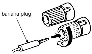
Turn clockwise to tighten, then insert the banana plug.
- Precautions when connecting speakers If a speaker is placed near a TV or video monitor, the colors on the screen may be disturbed by the speaker's magnetism. If this should happen, move the speaker away to a position where it does not have this effect.
SPEAKER SYSTEMS
System B


SPEAKER SYSTEMS
System A


Protector circuit
- This unit is equipped with a high-speed protection circuit. This circuit protects the internal circuitry from damage due to large currents flowing if the speaker jacks are not completely connected or if an output is generated by a short circuit.
In such a case, the protection circuit will operate to cut off the output to the speakers. Should this happen, turn the power off and check the speaker connections. Then turn the power on again. After muting for several seconds, the receiver should be operating normally.
If the protection circuit is activated again even though there are no problems with the wiring or the ventilation around the unit, switch off the power and contact a DENON service center.
Note on speaker impedance
- The protector circuit may be activated if the set is played for long periods of time at high volumes when speakers with an impedance lower than the specified impedance (for example speakers with an impedance of lower than 4/ohms ) are connected. If the protector circuit is activated, the speaker output is cut off. Turn off the set's power, wait for the set to cool down, improve the ventilation around the set, then turn the power back on.
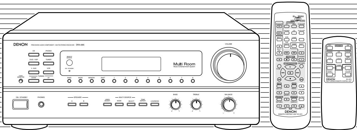
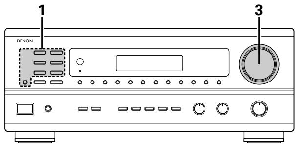
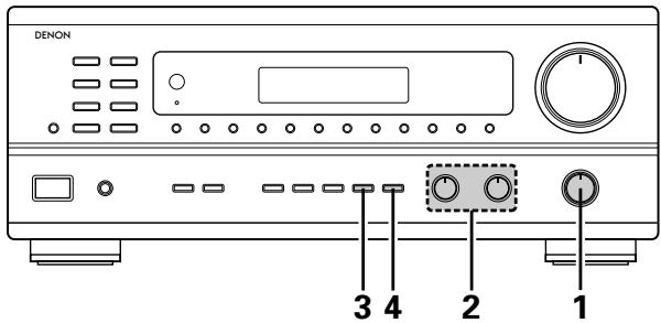
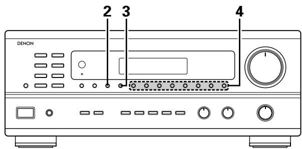
6 PART NAMES AND FUNCTIONS
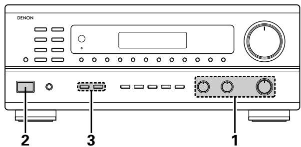
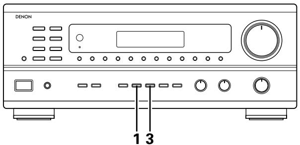
Front Panel
- For details on the functions of these parts, refer to the pages given in parentheses ( ).
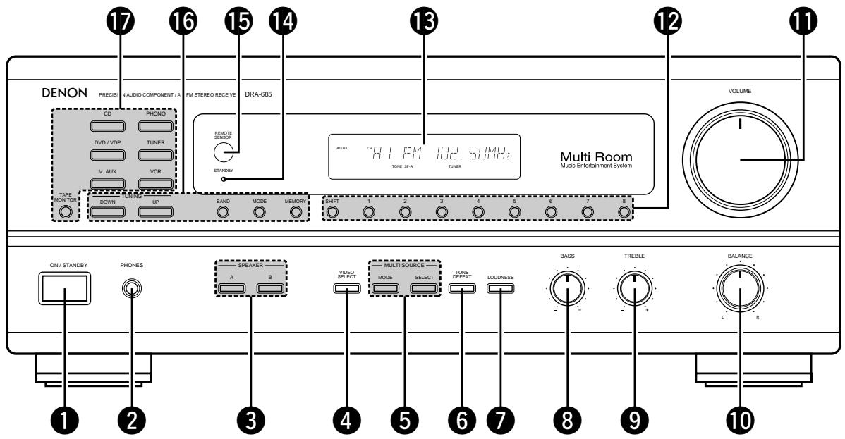
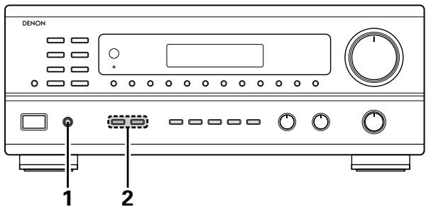
Power operation switch (17)
2 Headphone jacks (PHONES) (22)
3 SPEAKER A/B buttons. (17)
VIDEO SELECT button (22)
5 MULTI SOURCE buttons (19, 20)
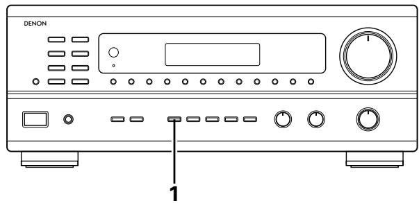
6 TONE DEFECT button (18)
7 LOUDNESS button (18)
BASS adjustment control (18)
9 TREBLE adjustment control (18)
10 BALANCE control. (18)
11 VOLUME control (18)
12 Preset memory selector buttons (26)
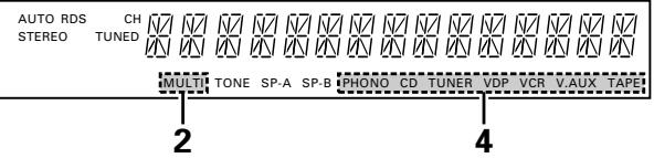
13 Display
14 Power indicator. (17)
Remote control sensor (REMOTE SENSOR) (12)
16 TUNING buttons (25, 26)
17 Input source selector buttons (18)
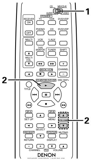
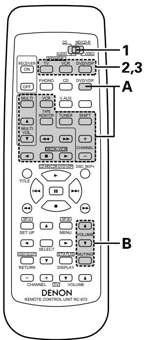
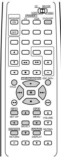
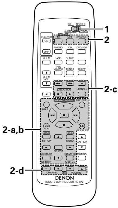
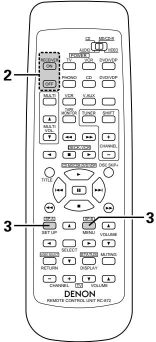
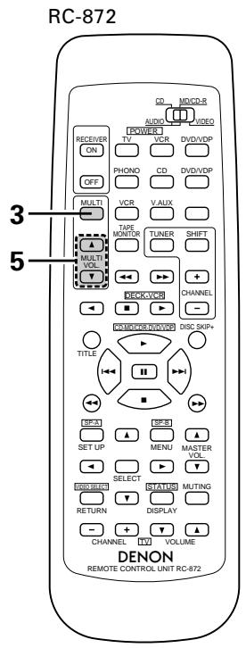
Remote control unit (RC-872)
- For details on the functions of these parts, refer to the pages given in parentheses ( ).
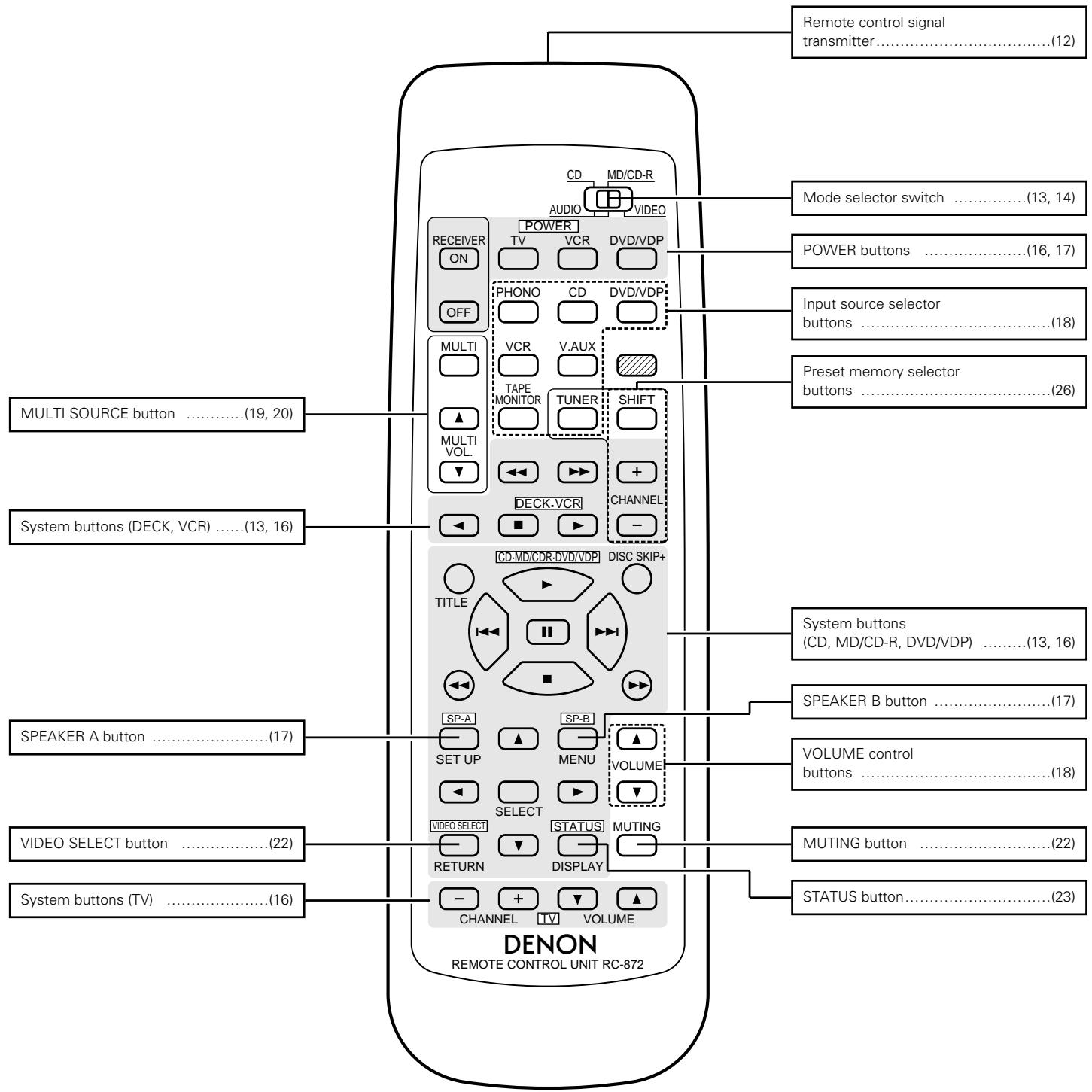
NOTE:
- The shaded buttons do not function with the this unit.
(Nothing happens when they are pressed.)
7 REMOTE CONTROL UNIT
Following the procedure outlined below, insert the batteries before using the remote control unit.
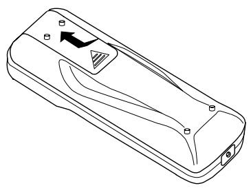
Range of operation of the remote control unit
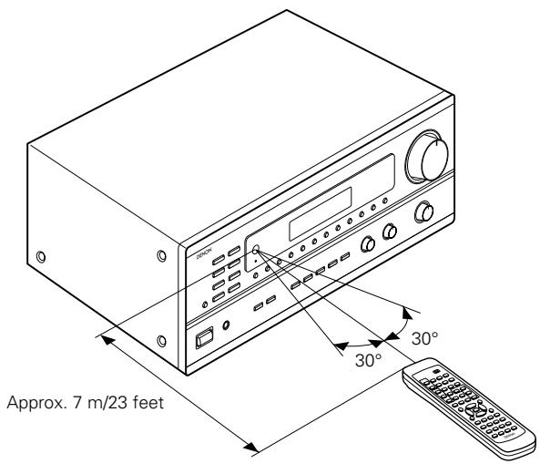
Point the remote control unit at the remote control sensor as shown on the diagram at the left.
NOTES:
- The remote control unit can be used from a straight distance of approximately 7 meters/23 feet, but this distance will shorten or operation will become difficult if there are obstacles between the remote control unit and the remote control sensor, if the remote control sensor is exposed to direct sunlight or other strong light, or if operated from an angle.
- Neon signs or other devices emitting pulse-type noise nearby may result in malfunction, so keep the set as far away from such devices as possible.
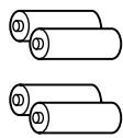
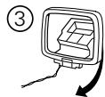
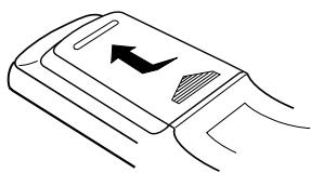
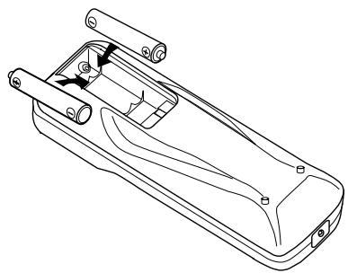
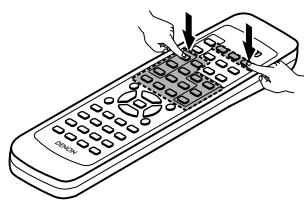
Inserting the batteries
For remote control unit (RC-872)
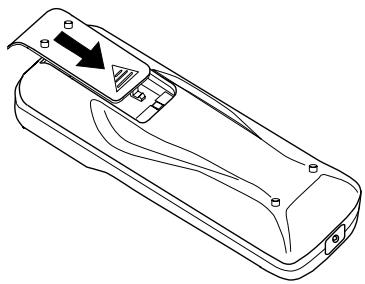
① Press as shown by the arrow and slide off.
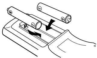
② Insert the R6P/AA batteries properly, as shown on the diagram.
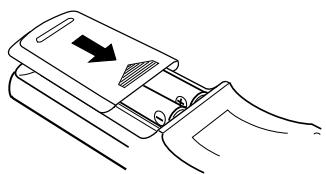
③ Close the lid.
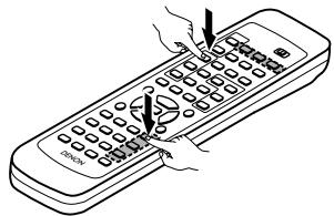
For multi-source remote control unit (RC-873)
① Press as shown by the arrow and slide off.
② Insert the R03/AAA batteries properly, as shown on the diagram.
③ Close the lid.
NOTES:
- Be sure the polarities are correct. (See the illustration inside the battery compartment.)
- Remove the batteries if the remote control transmitter will not be used for an extended period of time.
- If batteries leak, dispose of them immediately. Avoid touching the leaked material or letting it come in contact with clothing, etc. Clean the battery compartment thoroughly before installing new batteries.
- Even if less than a year has passed, replace the batteries with new ones if the set does not operate even when the remote control unit is operated nearby the set. (The included battery is only for verifying operation. Replace it with a new battery as soon as possible.)
- When replacing the batteries, after removing them wait for about one minute before inserting the new batteries.
Operating DENON audio components
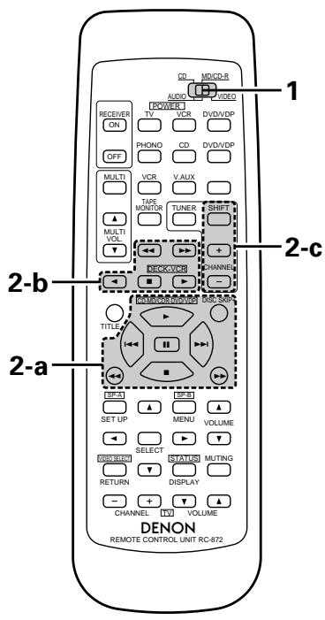
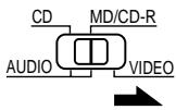
DENON remote-controllable audio components can be controlled using this unit's remote control unit. Note that some components, however, cannot be operated with this remote control unit.
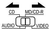
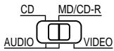
1 Set the slide switch to the position for the component to be operated (CD or MD/CD-R).
Use the buttons shown below to operate the audio component. For details, refer to the respective component's manual.
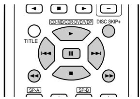
a. For CD player and MD/CD-R
: Manual search (reverse and forward)
:Stop
: Play
1:Auto search
:Pause
DISC : Disc selection
SKIP+ (CD changer only)
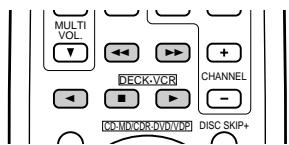
b. For tape deck (DECK)
: Reverse
Forward
:Stop
Forward play
: Reverse play
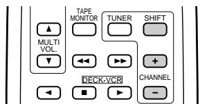
c. For TUNER
SHIFT : Switch preset channel range
CHANNEL: Preset channel
+,- up/down
NOTE:
- Tape deck (DECK) and TUNER can be operated when the switch is at "AUDIO" position.
Preset memory (Audio component)
DENON components can be operated by setting the preset memory for MD or CD-R.
1 Set the slide switch to "MD/CD-R".
2 Holding in the PLAY (▶) button, press the button for the components you want to set. (Refer to table 1.)
Table 1: Combinations of Personal System Codes
| ▲ VOLUME | ▼ VOLUME | |
| PLAY (►) | MD | CD-R |
NOTE:
- The memory can only be preset for either the MD or the CD-R.
※ Preset codes set upon shipment from the factory and when reset.
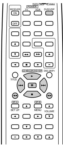
Preset memory (Video component)
DenON and other makes of components can be operated by setting the preset memory for your make of video component. Operation is not possible for some models.
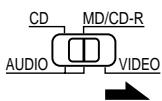
1 Set the slide switch to "VIDEO".
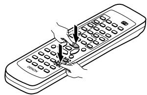
2 Holding in the POWER button of the components (DVD/VDP, VCR or TV) you want to set, press the button for the corresponding manufacturer in block A. (Refer to Table 2.)
3 Next, while holding in the POWER button, press the button for the code in block B. (Refer to Table 2.)
4 To continue registering other components, repeat steps 2 to 3.
This remote control unit can be used to operate components of other manufacturers without using the learning function by registering the manufacturer of the component as shown on Table 2.
Table 2: Combinations of Personal System Codes for Different Manufacturers
"DVD"
| A\B | MASTER VOL. | MASTER VOL. | MUTING |
| DVD/VDP | - | - | - |
| MULTI | DENON A | DENON B | - |
| VCR | - | - | - |
| MULTI VOL.▲ | - | - | - |
| TAPE MONITOR | PANASONIC | - | - |
| TUNER | - | - | - |
| SHIFT | - | - | - |
| MULTI VOL.▼ | - | - | - |
| TAPE | SONY | - | - |
| TAPE | PIONEER | - | - |
| TUNER | TOSHIBA | - | - |
| TAPE | - | - | - |
| TAPE | - | - | - |
| TAPE | - | - | - |
| TUNER | - | - | - |
"VDP"
| A\B | MASTER VOL. | MASTER VOL. | MUTING |
| DVD/VDP | DENON A | DENON B | DENON C |
| MULTI | — | — | — |
| VCR | MITUBISHI | — | — |
| MULTI VOL.▲ | PANASONIC | — | — |
| TAPE MONITOR | — | — | — |
| TUNER | SONY | — | — |
| SHIFT | PIONEER | — | — |
| MULTI VOL.▼ | — | — | — |
| TAPE | — | — | — |
| TAPE | — | — | — |
| TUNER | — | — | — |
| TAPE | PHILIPS | — | — |
| TAPE | RCA | — | — |
| TAPE | — | — | — |
| TUNER | — | MAGNAVOX | — |
NOTE:
- The memory can only be preset for either the DVD or the VDP.
※ Preset codes set upon shipment from the factory and when reset.
"VCR"
| A\B | MASTER VOL. | MASTER VOL. | MUTING |
| DVD/VDP | — | — | — |
| MULTI | HITACHI A | HITACHI B | — |
| VCR | MITUBISHI A | MITUBISHI B | MITUBISHI C |
| MULTI VOL.▲ | PANASONIC A | PANASONIC B | PANASONIC C |
| TAPE MONITOR | JVC (VICTOR) A | JVC (VICTOR) B | JVC (VICTOR) C |
| TUNER | SONY A | SONY B | SONY C |
| SHIFT | PIONEER | — | — |
| MULTI VOL.▼ | TOSHIBA A | TOSHIBA B | — |
| TAPE | SANYO A | SANYO B | — |
| TAPE | SHARP A | SHARP B | — |
| TUNER | NEC A | NEC B | NEC C |
| TAPE | PHILIPS A | PHILIPS B | PHILIPS C |
| TAPE | RCA A | RCA B | — |
| TAPE | GENERAL ELECTRIC A | GENERAL ELECTRIC B | — |
| TUNER | MAGNAVOX A | MAGNAVOX B | MAGNAVOX C |
"TV"
※ Preset codes set upon shipment from the factory and when reset.
NOTES:
- The signals for the pressed buttons are emitted while setting the preset memory. To avoid accidental operation, cover the remote control unit's transmitting window while setting the preset memory.
- Some models and years of manufacture of components of the manufacturers listed on Table 2 cannot be used.
- The unit is equipped with several types of remote control codes which depend on the manufacturer. If there is no operation when set to A, please change the setting to B or C and try again.
Operating a video component stored in the preset memory
1 Set the slide switch to "VIDEO".
Operate the video component.
- For details, refer to the component's operating instructions.
※ Some models cannot be operated with this remote control unit.
a. For DVD player
POWER : Power on/off
■ : Stop
▶ : Play
|▶,▶| : Auto search (cue)
■ | Pause
TITLE : Call out title
MENU : Call out menu
DISPLAY : Switch display
SET UP : DVD setup
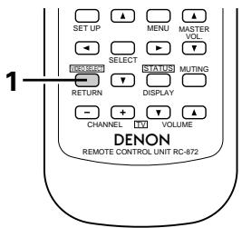
RETURN : Menu return
▲,▼ : Cursor up/down
▲,▶ : Cursor left/right
SELECT : Enter setting
DISC SKIP + : Disc selection
NOTE:
Some manufacturers use different names for the DVD remote control buttons, so also refer to the instructions on remote control for that component.
b. For video disc player (VDP)
c. For video deck (VCR)
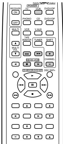
POWER : Power on/off
: Manual search (reverse and forward)
:Stop ▲ Play 1,Auto search (cue) :Pause
POWER : Power on/off
: Manual search (reverse and forward)
:Stop ▲ :Play
CHANNEL: Switch channel
+,-
d. For TV
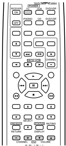
POWER : Power on/off
VOLUME : Volume
, up/down
CHANNEL: Switch channel
+,一
NOTE:
The TV can be operated when the switch is at any position.
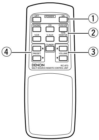
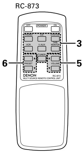
Multi-source remote control unit (RC-873)
This is a remote control unit for multi-source and multi-zone playback.
Buttons ② can not be used when the main unit's multi-source mode is set to the REC OUT mode.
Buttons ④ can only be used when the main unit's multi-source mode is set to the MULTI mode.
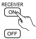
(1) The main unit's POWER (ON, OFF) buttons.
② MULTI SOURCE terminal output function control buttons (PHONO, TUNER, CD, DVD/VDP, VCR, V.AUX and TAPE).
③ MULTI SOURCE terminal output level control buttons (VOLUME up and down).
※ DEFAULT SETTING (MULTI VOLUME LEVEL) :---- dB (MINIMUM)
④ PRESET up and down buttons (when MULTI SOURCE function is set to TUNER).
8 OPERATIONS
Before operating
Preparations:
Check that all connections are proper.
1 Set to the center position.
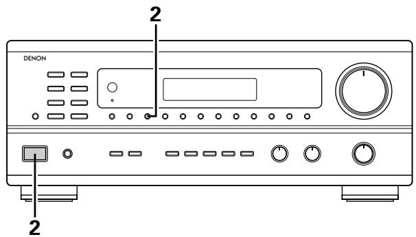
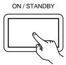
Turn on the power.
Press the power operation switch (button).
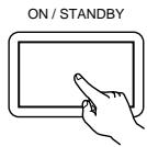
ON/STANDBY
When the button is pressed, the power turns on and the display lights.
When pressed again, the power turns off, the standby mode is set and the display turns off.
Several seconds are required from the time the power switch is set to the "ON" position until sound is output. This is due to the built-in muting circuit that prevents noise when the power switch is turned on and off.
Set the power operation switch to this position, the power on and off from the included remote control unit.
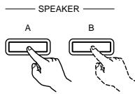
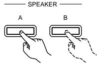
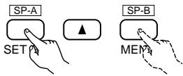
2 Select the front speakers.
Press the SPEAKER A or B button turn the speaker on.
※ Set the slide switch to "AUDIO".
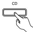
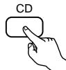
Playing the program source
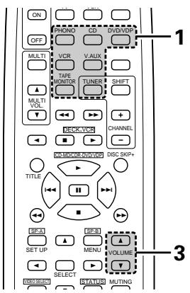
Press the button for the program source to be played.
EX 2: TAPE

- Press the button once to switch the source to TAPE MONITOR input, again to cancel input.
2 Start playback on the selected component.
For operating instructions, refer to the various components' manuals.
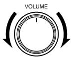
3 Adjust the VOLUME control.

Adjusting the BALANCE, TONE, and LOUDNESS control
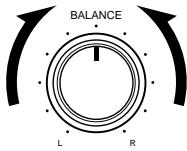
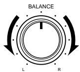
1 Adjust the left/right BALANCE control. Turn the control counterclockwise to reduce the volume of the right channel, clockwise to reduce the volume of the left channel.
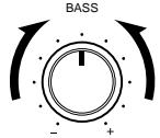
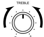
2 Adjust the BASS and TREBLE control.
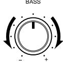
Turn the control clockwise to increase the bass, counterclockwise to decrease it.
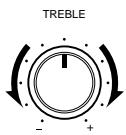
Turn the control clockwise to increase the treble, counterclockwise to decrease it.
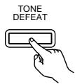
3 Press the TONE DEFEAT button. Use this when you do not want to adjust the sound.
4 Press the LOUDNESS button. Press the loudness button ON when listening to music at a low volume. The low notes and high notes will be corrected to produce a natural sound.
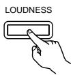
※ LOUDNESS button can be used when the TONE DEFEAT ON mode.
Multi-Source recording/playback
The Multi-Source function allows you to record a source other than the source currently playing or to output its signal to the MULTI SOURCE output terminal.
■ Recording a source other than the one currently playing (REC OUT mode)
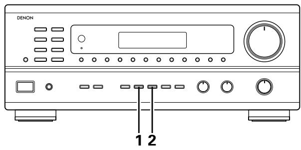
DISPLAY
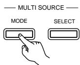
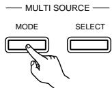
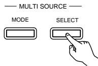
Press the MULTI SOURCE MODE button until "REC OUT" appears on the display.
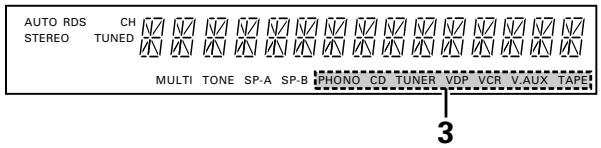
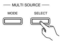
2 Select the source to be output to the recording output terminal. Press the MULTI SOURCE SELECT button repeatedly until the desired source appears on the display.
※ The REC OUT mode cannot be set from the remote control unit.
The selected source is indicated.
※ The signals of the source selected with the REC OUT mode are also output from the MULTI SOURCE AUDIO/VIDEO OUT terminals.
※ To cancell the REC OUT mode. Press the MULTI SOURCE MODE button repeatedly until "SOURCE" appears on the display.
■ Playing a source other than the one currently playing in a different room (MULTI mode)
DISPLAY
Press the MULTI SOURCE MODE button repeatedly until "MULTI OUT" appears on the display.
2 Turn on the "MULTI" indicator.
3 Select the source to be output to the MULTI SOURCE output terminal. Press the MULTI SOURCE SELECT button repeatedly until the desired source appears on the display.

(RC-872)
※ When the MULTI SOURCE button on the RC-872 remote control unit is pressed, the MULTI mode is set directly (the "MULTI" indicator lights), and the source to be output from the MULTI SOURCE terminals can be selected.
※ When the PHONO TAPE buttons on the RC-873 multi source remote control unit is pressed, the MULTI mode is set directly (the "MULTI" indicator lights), and the source to be output from the MULTI SOURCE terminals can be selected directly. (This cannot be selected when the main unit is in the REC OUT mode.)
The selected source is indicated.
※ To cancel the MULTI mode.
Press the MULTI SOURCE MODE button or the MULTI button on the RC-872 remote control unit repeatedly until "SOURCE" appears on the display.
NOTE:
The signals of the source selected in the MULTI mode are also output from the TAPE and VCR recording output terminals.
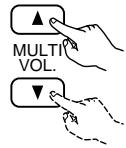
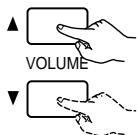
The output level of the MULTI SOURCE AUDIO terminals can be controlled using the MULTI VOLUME and buttons on the RC-872 remote control unit or the VOLUME up and down buttons on the RC-873 multi source remote control unit.
(RC-872)
(RC-873)
※ DEFAULT SETTING (MULTI VOLUME LEVEL) : - - - dB (MINIMUM)
6 When the MULTI SOURCE function is set to TUNER, the preset channel can be selected using the PRESET and buttons on the RC-873 multi source remote control unit. (This is only possible when the main unit is in the MULTI mode.)
NOTE:
Note that this also switches the preset reception channel on the main unit when playing or recording the tuner in the MULTI mode.
■ Multi-source and multi-zone playback
- When the outputs of the MULTI SOURCE AUDIO/VIDEO OUT terminals are wired and connected to power amplifiers or TV displays installed in other rooms, different sources can be played in rooms other than the main room in which the this unit and the playback devices are installed. (Refer to SUB ROOM-1 on the diagram.)
- When the output of the SPEAKER SYSTEM-B terminals is wired and connected to speakers in a sub room, the same source can be played in both the main room and sub room. Set the this unit's SPEAKER A/B selector according to the room in which the source is to be played. (Refer to SUB ROOM-2 on the diagram.)
- When a separately sold room-to-room remote control unit (DENON RC-616 or 617) is wired and connected between the main room and the sub room, the remote-controllable devices in the main room can be controlled from the sub room using the remote control unit.
※With SUB-ROOM-1 multi-source playback, the this unit's MULTI SOURCE output can be controlled with the included RC-873 multi source remote control unit.
Operations on the RC-873 remote control unit other than turning the multi source output volume up and down can not be performed when the main unit is in the REC OUT mode.
※With SUB ROOM-2 playback, the this unit and DENON CD players or tape decks etc. can be controlled using the included RC-872 system remote control unit.
To control playback devices other than the ones above, either use that device's remote control unit or preset a separately sold programmable remote control unit (DENON RC-770, etc.).
NOTE:
- Use a 75 Ω/ohms coaxial pin-plug cord for video signals to connect and wire the MULTI SOURCE VIDEO output. For the AUDIO output, use high quality pin-plug cords and wire in such a way that there is no humming or noise.
- For instructions on installation and operation of separately sold devices, refer to the devices' operating instructions.
Use this switch to monitor a video source other than the audio source.
1 Holding the VIDEO SELECT button until the desired source appears on the display.


※ Set the slide switch to "AUDIO".
The video source switches as follows each time the button is pressed:

Cancelling simulcast playback.
- Press the VIDEO SELECT button again.
- Switch the program source to the component connected to the video.
Using the muting function
Use this to turn off the audio output temporarily.
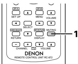
Press the MUTING button.
Cancelling MUTING mode. Press the MUTING button again.

- Caution:
Switching off the power of the unit will cancel the settings.
Listen with headphones
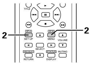
1 Connect the headphones to the headphones jack of the front panel.
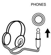
Press the SPEAKER A or B button turn the speaker off.
※ Set the slide switch to "AUDIO".
Front panel display
When an operation is performed on the remote control unit, that operation appears on the display, making it possible to check the operation visually.
The set's operating status can also be checked on the display using the procedure described below.
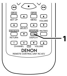
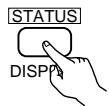
Press the STATUS button.
※ Set the slide switch to "AUDIO".
- The input and output sources and the setting, etc., appear in order on the display each time the button is pressed.
Recording the program source (recording the source currently being monitored)
1 Follow steps 1 to 3 under "Playing the program source".
2 Start recording on the tape or video deck. For instructions, refer to the component's operating instructions.
Simultaneous recording
The signals of the source selected with the function selector button are output simultaneously to the TAPE and VCR REC OUT jacks. If a total of two tape and/or video decks are connected and set to the recording mode, the same source can be recorded simultaneously on every decks.
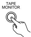
In addition, if the TAPE MONITOR button is pressed, the audio signals from the tape deck are output to the VCR AUDIO REC OUT jacks.
Tape monitor function
When a three-head tape deck is used, the sound actually being recorded can be monitored during recording by pressing the TAPE MONITOR button.
Press the button again to cancel monitoring.
This unit is equipped with a function for automatically searching for FM broadcast stations and storing them in the preset memory.
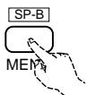
1 Switch off the unit.
2 Switch on the unit using the main unit's power operation switch while holding in the MEMORY button. The unit automatically begins searching for FM broadcast stations.

3 When the first FM broadcast station is found, that station is stored in the preset memory at channel A1. Subsequent stations are automatically stored in order at preset channels A2 to A8, B1 to B8, C1 to C8, D1 to D8 and E1 to E8, for a maximum of 40 stations.
4 Channel A1 is tuned in after the auto preset memory operation is completed.
NOTES:
- If an FM station cannot be preset automatically due to poor reception, use the "Manual tuning" operation to tune in the station, then preset it using the manual "Preset memory" operation.
- To interrupt this function, press the power operation button.
DEFAULTVALUE
| AUTO TUNER PRESETS | |
| A1 ~ A8 | 87.5/89.1/98.1/107.9/90.1/90.1/90.1 MHz |
| B1 ~ B8 | 520/600/1000/1400/1500/1710 kHz/90.1/90.1 MHz |
| C1 ~ C8 | 90.1 MHz |
| D1 ~ D8 | 90.1 MHz |
| E1 ~ E8 | 90.1 MHz |
Auto tuning
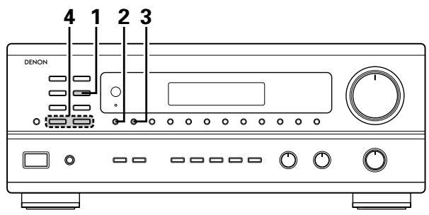
1 Set the input function to "TUNER".
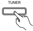
2 Watching the display, press the BAND button to select the desired band (AM or FM).
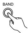
Press the MODE button to set the auto tuning mode.
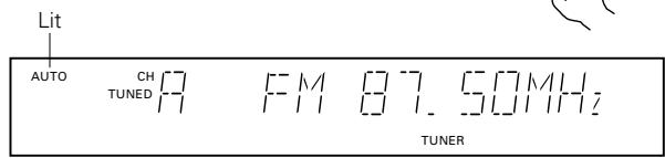
4 Press the TUNING UP or DOWN button.
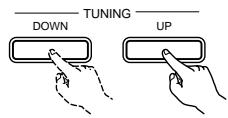
- Automatic searching begins, then stops when a station is tuned in.
NOTE:
- When in the auto tuning mode on the FM band, the "STEREO" indicator lights on the display when a stereo broadcast is tuned in. At open frequencies, the noise is muted and the "TUNED" and "STEREO" indicators turn off.
Manual tuning
1 Set the input function to "TUNER".
2 Watching the display, press the BAND button to select the desired band (AM or FM).
Press the MODE button to set the manual tuning mode. Check that the display's "AUTO" indicator turns off.
4 Press the TUNING UP or DOWN button to tune in the desired station. The frequency changes continuously when the button is held in.
NOTE:
- When the manual tuning mode is set, FM stereo broadcasts are received in monaural and the "STEREO" indicator turns off.
Preset memory
1 Use the "Auto tuning" or "Manual tuning" operation to tune in the station to be preset in the memory.
Press the MEMORY button.

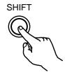
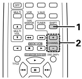
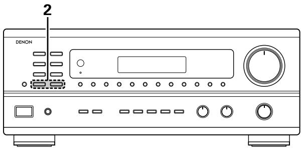
Press the SHIFT button and select the desired memory block (A to E).
Press the preset channel button (1 to 8) to select the desired preset channel (1 to 8).
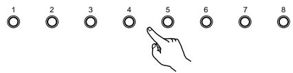
※ To preset other channels, repeat steps 1 to 4. A total of 40 broadcast stations can be preset — 8 stations (channels 1 to 8) in each of blocks A to E.
Recalling preset stations
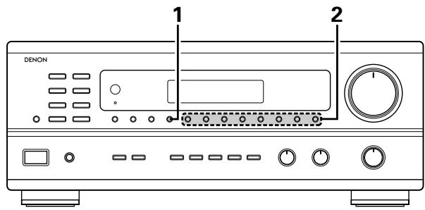
1 Watching the display, press the SHIFT button to select the preset memory block.


※ Set the slide switch to "AUDIO".
2 Watching the display, press the preset channel button (1 to 8) to select the desired preset channel. (When using the remote control unit, select the preset channel by pressing the preset channel button.)


10 INITIALIZATION OF THE MICROPROCESSOR
When the indication of the display is not normal or when the operation of the unit does not show the reasonable result, the initialization of the microprocessor is required by the following procedure.
1 Switch off the unit and remove the AC cord from the wall outlet.
2 Hold the following TUNING UP button and TUNING DOWN button, and plug the AC cord into the outlet.
3 Check that the entire display is flashing with an interval of about 1 second, and release your fingers from the 2 buttons and the microprocessor will be initialized.
11 LAST FUNCTION MEMORY
- This unit is equipped with a last function memory which stores the input and output setting conditions as they were immediately before the power is switched off.
- The unit also equipped with a back-up memory. This function provides approximately one week of memory storage when the main unit's power operation switch is off and with the power cord disconnected.
12 TROUBLESHOOTING
If a problem should arise, first check the following.
- Are all connections correct?
- Have you operated the receiver according to the Operating Instructions?
- Are the speakers, turntable other components operating property?
If this unit is not operating properly, check the items listed in the table below. Should the problem persist, there may be a malfunction.
Disconnect the power immediately and contact your store of purchase.
| Symptom | Cause | Measures | Page | |
| Common problems arising when listening to the CD, records, tapes, and FM broadcasts, etc. | DISPLAY not lit and sound not produced when power operation switch set to on. | • Power cord not plugged in securely. | • Check the insertion of the power cord plug. • Turn the power on with the remote control unit after turning the Power operation switch on. | 6 17 |
| DISPLAY lit but sound not produced. | • Speaker cords not securely connected. • Improper position of the audio function button. • Volume control set to minimum. • MUTING is on. | • Connect securely. • Set to a suitable position. • Turn volume up to suitable level. • Switch off MUTING. | 9, 10 18 18 22 | |
| — PROTECT — display appears. | • Speaker terminals are short-circuited. • Block the ventilation holes of the set. • The unit is operating at continuous high power conditions and/or inadequate ventilation. | • Switch power off, connect speakers properly, then switch power back on. • Turn off the set's power, then ventilate it well to cool it down. Once the set is cooled down, turn the power back on. • Turn off the set's power, then ventilate it well to cool it down. Once the set is cooled down, turn the power back on. | 9, 10 5 5 | |
| Sound produced only from one channel. | • Incomplete connection of speaker cords. • Incomplete connection of input/output cords. | • Connect securely. • Connect securely. | 9, 10 6 ~ 8 | |
| Positions of instruments reversed during stereo playback. | • Reverse connections of left and right speakers or left and right input/output cords. | • Check left and right connections. | 6 ~ 10 | |
| When playing records | Humming noise produced when record is playing. | • Ground wire of turntable not connected properly. • Incomplete PHONO jack connection. • TV or radio transmission antenna nearby. | • Connect securely. • Connect securely. • Contact your store of purchase. | 6 6 - |
| Howling noise produced when volume is high. | • Turntable and speaker systems too close together. • Floor is unstable and vibrates easily. | • Separate as much as possible. • Use cushions to absorb speaker vibrations transmitted by floor. If turntable is not equipped with insulators, use audio insulators (commonly available). | - - | |
| Sound is distorted. | • Stylus pressure too weak. • Dust or dirt on stylus. • Cartridge defective. | • Apply proper stylus pressure. • Check stylus. • Replace cartridge. | - - | |
| Volume is weak. | • MC cartridge being used. | • Replace with MM cartridge or use a head amplifier or step-up transformer. | 6 | |
| Remote control unit. | This unit does not operate properly when remote control unit is used. | • Batteries dead. • Remote control unit too far from this unit. • Obstacle between this unit and remote control unit. • Different button is being pressed. • ⊕ and ⊕ ends of battery inserted in reverse. | • Replace with new batteries. • Move closer. • Remove obstacle. • Press the proper button. • Insert batteries properly. | 12 12 12 - 12 |
13 SPECIFICATIONS
Audio section
(Power amplifier)
Rated output: 100 W + 100 W (8 Ω/ohms, 20 Hz ~ 20 kHz with 0.05 % T.H.D.)
Output terminals: A or B 4 to 16 Ω/ohms
A + B 8 to 16 Ω/ohms
(Analog)
LINE input - PRE OUT
Input sensitivity/input impedance: 200 mV / 47 k/ kohms
Frequency response: 10Hz 50kHz ± 1.5 dB
S/N ratio: 100 dB (IHF-A weighted)
Total harmonic distortion: 0.009 % (-3 dB at rated output,8 Ω/ohms) (1 kHz)
Rated output: 1.2 V
PHONO input -REC OUT
Input sensitivity/input impedance: 3.0mV / 47k / kohms
RIAA deviation: ±0.5 dB (20 Hz ~ 20kHz)
S/N ratio: 74 dB (IHF-A weighted, with 5 mV input)
Total harmonic distortion: 0.03% (1 kHz, 3V)
Rated output/Maximum output: 150mV / 7V
Video section
(standard video jacks)
Input/output level and impedance: 1 V p-p, 75 Ω/ohms
Frequency response: 5Hz 10MHz + 1 -3 dB
- Tuner section
| [FM] (note: μV at 75Ω /ohms, 0 dBf = 1 × 10-15W) | [AM] | |
| Receiving range: | 87.50 MHz ~ 107.90 MHz | 520 kHz ~ 1710 kHz |
| Usable sensitivity: | 1.4 μV (14.2 dBf) | 18 μV |
50 dB quieting sensitivity: MONO 2.8 V (20.2 dBf)
STEREO 23μV (38.5 dBf)
S/N ratio: MONO 80 dB (IHF-A weighted)
STEREO 75 dB (IHF-A weighted)
Total harmonic distortion: MONO 0.15% (1kHz)
STEREO 0.3% (1kHz)
- General
Power supply: AC 120 V, 60 Hz
Power consumption: 3.4 A
Maximum external dimensions: 434 (W) x 171 (H) x 416 (D) mm (17-1/16" x 6-23/32" x 16-3/8")
Weight: 10.0kg (22 lbs)
- Remote control unit
RC-872
Batteries: R6P/AA Type (two batteries)
External dimensions: 54 (W) x 172 (H) x 27.2 (D) mm (2-1/8" x 6-3/4" x 1-1/16")
Weight: 100 g (Approx. 6 oz) (including batteries)
RC-873
Batteries: R03/AAA Type (two batteries)
External dimensions: 47.5 (W) x 127 (H) x 18 (D) mm (1-27/32" x 5 x 11/16")
Weight: 70 g (Approx. 2.4 oz)
- For purposes of improvement, specifications and design are subject to change without notice.
INTRODUCTION
| ▲ VOLUME | ▼ VOLUME | |
| PLAY (►) | MD | CD-R |

REMARQUES:
Lecture multi-source et multi-zone
SYSTEME DE DIVERTISSEMENT MUSICAL MULTI-PIECE
Entree PHONO -REC OUT
(Prises video standard)
- AM-FM STEREO RECEIVER
- DRA-685
- OPERATING INSTRUCTIONS
- MODE D'EMPLOI
- CAUTION
- ATTENTION
- INTRODUCTION
- TABLE OF CONTENTS
- ■ ACCESSORIES
- Check that the following parts are included in addition to the main unit:
- BEFORE USING
- Pay attention to the following before using this unit:
- - Moving the set
- - Before turning the power operation switch on
- CAUTIONS ON INSTALLATION
- CAUTIONS ON HANDLING
- FEATURES
- Multi Room Music Entertainment System
- Powerful, Versatile Amplifier
- Signal Level Divided Construction (SLDC)
- Remote Control Functions
- CONNECTIONS
- Connecting the audio components
- Connections for playback:
- AC OUTLETS
- - SWITCHED
- NOTE:
- Connecting the video equipments
- Connecting a video decks
- Video input/output connections:
- Connecting the audio output jacks
- Connecting the antenna terminals
- AM loop antenna assembly
- Connection of AM antennas
- Note to CATV system installer:
- NOTES:
- Speaker system connections
- Speaker Impedance
- Connecting the speaker terminals
- Protector circuit
- Note on speaker impedance
- PART NAMES AND FUNCTIONS
- Front Panel
- Remote control unit (RC-872)
- REMOTE CONTROL UNIT
- Range of operation of the remote control unit
- Inserting the batteries
- For remote control unit (RC-872)
- For multi-source remote control unit (RC-873)
- Operating DENON audio components
- Preset memory (Audio component)
- Preset memory (Video component)
- Operating a video component stored in the preset memory
- Multi-source remote control unit (RC-873)
- OPERATIONS
- Before operating
- Preparations:
- Playing the program source
- Adjusting the BALANCE, TONE, and LOUDNESS control
- Multi-Source recording/playback
- ■ Recording a source other than the one currently playing (REC OUT mode)
- ■ Playing a source other than the one currently playing in a different room (MULTI mode)
- DISPLAY
- ■ Multi-source and multi-zone playback
- Using the muting function
- Listen with headphones
- Front panel display
- Recording the program source (recording the source currently being monitored)
- Simultaneous recording
- Tape monitor function
- DEFAULTVALUE
- Auto tuning
- Manual tuning
- Preset memory
- Recalling preset stations
- INITIALIZATION OF THE MICROPROCESSOR
- LAST FUNCTION MEMORY
- TROUBLESHOOTING
- SPECIFICATIONS
- Audio section
- (Analog)
- PHONO input -REC OUT
- Video section
- - Tuner section
- - General
- - Remote control unit
- RC-873
- REMARQUES:
- Lecture multi-source et multi-zone
- SYSTEME DE DIVERTISSEMENT MUSICAL MULTI-PIECE
Brand : DENON
Model : DRA-685
Category : Audio Amplifier