
PP 40 DCDR F - Cooker SCHOLTES - Free user manual and instructions
Find the device manual for free PP 40 DCDR F SCHOLTES in PDF.

| Product type | Built-in gas hob |
| Brand | SCHOLTES |
| Model | PP 40 DCDR F |
| Number of burners | 5 (including one dual flame inner/outer burner) |
| Maximum total power | 12.9 kW |
| Compatible gas types | Natural gas (G20), Butane (G30), Propane (G31) |
| Ignition | Integrated electronic spark ignition |
| Safety device | Flame safety thermocouple |
| Surface material | Stainless steel (estimate) |
| Cleaning | Removable burners washable with hot water and mild detergent |
| Installation class | Class 1 or 3 depending on edge height (edge height 87 mm) |
| Electrical supply | 230 V ~ 50 Hz |
| Gas connection | 1/2 cylindrical male gas |
| Nominal gas supply pressure | G20: 20 mbar, G30: 28-30 mbar, G31: 37 mbar |
| Net weight | Approximately 12 kg (estimate) |
| Dimensions (W x D x H) | Not specified in the manual |
Frequently Asked Questions - PP 40 DCDR F SCHOLTES
User questions about PP 40 DCDR F SCHOLTES
0 question about this device. Answer the ones you know or ask your own.
Ask a new question about this device
Download the instructions for your Cooker in PDF format for free! Find your manual PP 40 DCDR F - SCHOLTES and take your electronic device back in hand. On this page are published all the documents necessary for the use of your device. PP 40 DCDR F by SCHOLTES.
USER MANUAL PP 40 DCDR F SCHOLTES
Electrical connection
Gas connection
Data plate
Burner and nozzle specifications
Description of the appliance, 20
Overall view
Start-up and use, 21
Advice when using burners
Precautions and tips, 22
General safety
Disposal
PP 40 DCDR F...
PP 40 DCDR SF...
PP 40 TC F...
PP 40 TC SF...
B PP 40DCDR/CS...
B PP 40DCDR...
B PP 40TC/CS...
B PP 40TC...
Care and maintenance, 23
Switching the appliance off
Cleaning the appliance
Gas tap maintenance
Troubleshooting, 24
! Please keep this instruction booklet in a safe place for future reference. If the appliance is sold, given away or moved, please make sure the booklet is also passed on to the new owners so that they may benefit from the advice contained within it.
! Please read this instruction booklet carefully: it contains important information on installation, operation and safety.
Positioning
! Do not let children play with the packaging material;
it should be disposed of in accordance with local separated waste collection standards (see Precautions and tips).
! The appliance must be installed by a qualified professional in compliance with the instructions provided. Incorrect installation may damage property or cause harm to people or animals.
! The appliance may only be installed in permanently-ventilated rooms, in accordance with current national regulations and subsequent amendments. The following requirements must be observed:
- The room must be fitted with an air extraction system which expels any combustion fumes produced. This may consist of a cooker hood or an electric fan which starts automatically every time the appliance is switched on.
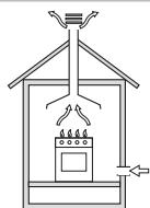
In a chimney stack or branched flue. exclusively for cooking appliances)
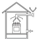
Directly to the Outside
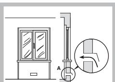
Examples of ventilation holes for combustant air.
Enlarging the ventilation slot between window and floor.
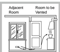
- The room must also allow for proper air circulation, as air is needed for combustion to occur normally. The flow of air must not be less than 2m3/h per kW of installed power.
The air circulation system may take air directly from the outside environment by means of a pipe with an inner cross section of at least 100 cm2 ; the opening must not be vulnerable to any type of blockages.
The system can also provide the air needed for combustion indirectly, i.e. from adjacent rooms fitted with air circulation ducts as described above. However, these rooms must not be shared living rooms, bedrooms or rooms presenting a fire hazard.
- Liquid petroleum gas sinks to the floor as it is heavier than air. Therefore, rooms containing LPG cylinders must also be equipped with vents in order to allow gas to escape in the event of a leak. As a result LPG cylinders, whether partially or completely full, must not be installed or stored in rooms or storage areas which are below ground level (cellars, etc.). Only the cylinder currently being used should be kept in the room. It must not be exposed to direct heat sources (ovens, fireplaces, stoves, etc.) which could raise the temperature of the cylinder above 50ircC .
Built-in appliance
Gas and mixed hobs are manufactured with type X degree protection against overheating; it is therefore possible to install the appliance next to kitchen cabinets which are no taller than the worktop. The following precautions must be taken when installing the hob:
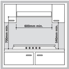
- Kitchen cabinets which are adjacent to the appliance and taller than the top of the hob must be at least 50 mm from the edge of the hob.
- Cooker hoods must be installed in accordance with their corresponding installation instruction manuals and at a
minimum distance of 700 mm from the hob.
- Place the wall cabinets adjacent to the hood at a minimum height of 540 mm from the hob (see Figure).
If the hob is installed beneath a wall cabinet, the latter must be situated at a minimum of 700 mm above the hob (see Figure).
Installing sit-on hobs
All the necessary precautions must be taken in order to install the appliance according to current accident-prevention regulations for gas and electrical connections. To ensure sit-on hobs installed in kitchen cabinets operate correctly, the minimum distances shown in Fig. 1 should be observed. All adjacent surfaces and the back panel should also be able to withstand an overheating temperature of 65ircC .
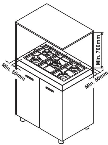
Fig. 1
Fitting the hob to the cabinet
There are three different groups of appliance as far as installation is concerned:
Fig. 2
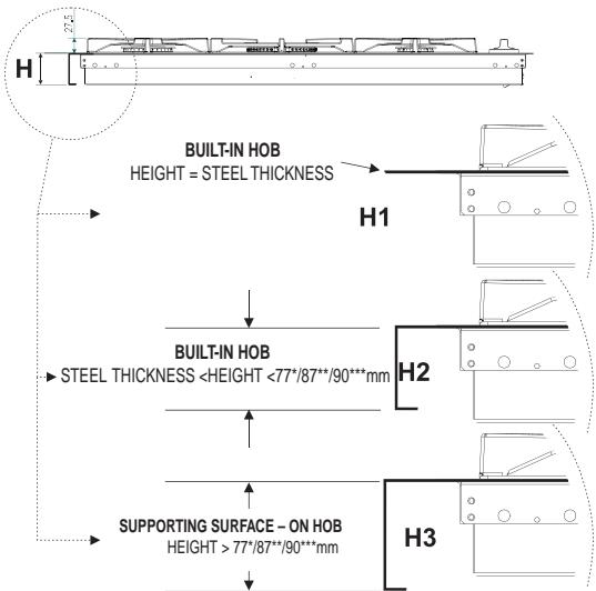
77* for models PP 40 TC F...PP 40 TC SF...-B PP 40TC/CS... 87 for models PP 40 DCDR F...PP 40 DCDR SF...-B PP 40DCDR/CS... 90* for models BP 40 TC...-B PP 40DCDR...
1-Built-in hobs to be slotted in (Class 3 - see Figure 2, detail H1). In this case it is necessary to make a hole in the worktop whose measurements match those of the hob. The measurement at the side should be reduced by 1cm so as to ensure that 1 cm of the perimeter of the hob overlaps with and rests on top of the supporting surface. To slot in the hob flush with the worktop, the cut-out on this supporting surface must be lowered (see Figure 4a), so that both the edge of the hob and the seal underneath it can be positioned there. Before fitting the hob to the worktop, position the seal provided along the perimeter of the hob, as illustrated in figure 4b. Brackets for fixing worktops to the cabinet have been provided, and these should be fitted as shown in detail S (fig. 3).
2-Built-in hobs (Class 3) with edges lower than 77/87*mm (see Figure 2, detail H2); to install this type of hob, a hole large enough to accommodate the whole lower casing of the appliance must be made in the worktop intended to be underneath the hob. Remember to leave a gap of at least 1 cm between the lower casing and the worktop around the whole perimeter of the appliance (the underside of the casing can, however, touch the surface below it). To fit the appliances, follow the instructions given above in point 1 or use any supplementary instruction leaflet that is provided in special cases.
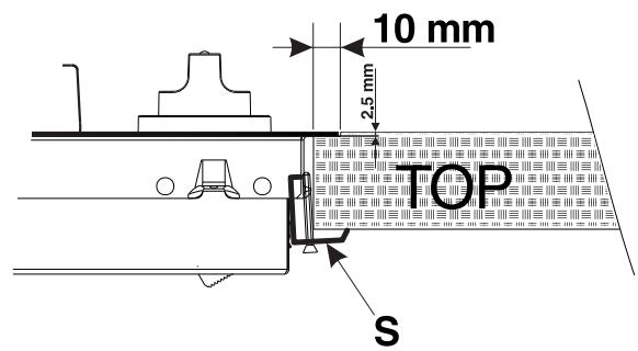
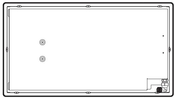
Fig. 3
FOR MODELS: PP 40 DCDRF ... - PP 40 TCF
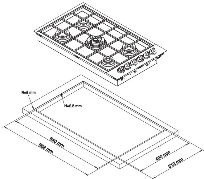
Fig. 4a
3- Sit-on hobs (Class 1) with edges higher than 77/ 87 / 90** mm (see Figure 2, detail H3); in this case, the lower casing of the hob does not protrude further than the edge of the appliance. Even when the hob is resting on the worktop, it will suffice to leave space for the gas supply tube and electricity supply cable.
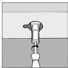
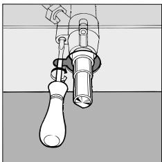
To fit this type of hob, follow the instructions below (Fig. 5):
Fix the two screws provided "A" at a distance from the back panel as shown in Figure 5, leaving the heads of the screws sticking out of the wood by 1.5 mm .
- Hook the hob onto the two screws "A" and push it towards the back.
Fix the appliance to the cabinet at the rear, using the two brackets "B" and the four screws "C" (these are all provided).
FOR MODELS: PP 40 DCDR SF... - PP 40 TC SF...
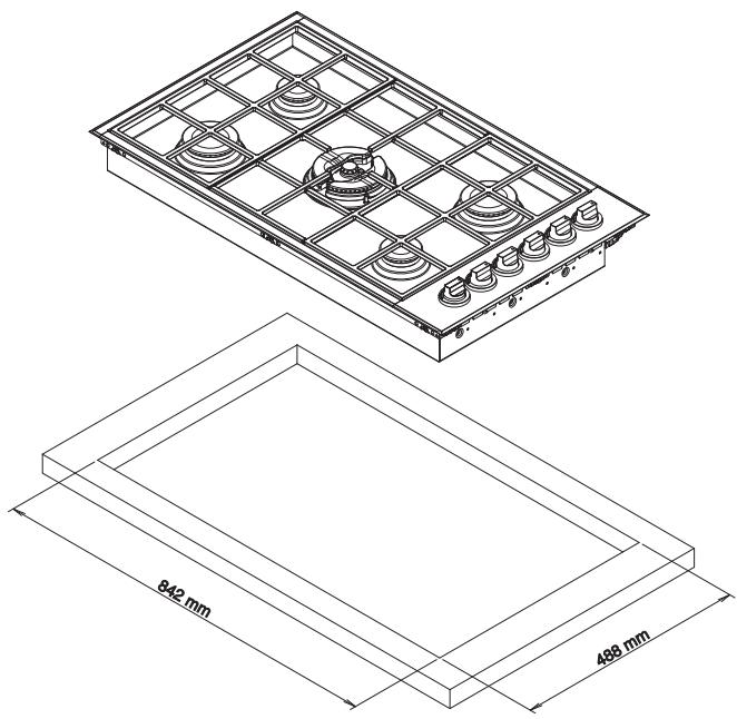
Fig. 4b
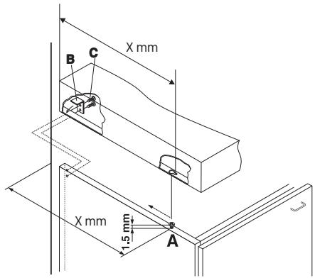
Fig. 5
N.B.: To maximise the efficiency of all technical maintenance procedures, the area around the hob must be easily accessible after it has been installed (i.e. there should be no completely closed-off elements).
Electrical connection
Hobs equipped with a three-pole power supply cable are designed to operate with alternating current at the voltage and frequency indicated on the data plate (this is located on the lower part of the appliance). The earth wire in the cable has a green and yellow cover. If the appliance is to be installed above a built-in electric oven, the electrical connection of the hob and the oven must be carried out separately, both for electrical safety purposes and to make extracting the oven easier.
Connecting the power supply cable to the electricity mains
Fit a standardised plug, suitable for the load indicated on the data plate, to the power supply cable.
The appliance must be directly connected to the mains using an omnipolar switch with a minimum contact opening of 3mm installed between the appliance and the mains. The switch must be suitable for the charge indicated and must comply with current electrical regulations (the earthing wire must not be interrupted by the switch). The supply cable must be positioned so that it does not come into contact with temperatures higher than 50ircC at any point.
! The installer must ensure that the correct electrical connection has been made and that it is compliant with safety regulations.
Before connecting the appliance to the power supply, make sure that:
- the appliance is earthed and the plug is compliant with the law;
- the socket can withstand the maximum power of the appliance, which is indicated on the data plate;
- the voltage falls between the values indicated on the data plate;
- the socket is compatible with the plug of the appliance. If the socket is incompatible with the plug, ask an authorised technician to replace it. Do not use extension cords or multiple sockets.
!Once the appliance has been installed, the power supply cable and the electrical socket must be easily accessible.
!The cable must not be bent or compressed.
!The cable must be checked regularly and replaced by authorised technicians only (see Assistance).
! The manufacturer declines any liability should these safety measures not be observed.
Gas connection
The appliance should be connected to the mains gas supply or to a gas cylinder in compliance with current national regulations and subsequent amendments. Before carrying out the connection, make sure the cooker is compatible with the gas supply you wish to use. If this is not the case, follow the instructions indicated in the paragraph "Adapting to different types of gas". When using liquid gas from a cylinder, install a pressure regulator which complies with current national regulations and subsequent amendments.
!Make sure that the gas supply pressure is consistent with the values indicated in Table 1, "Burner and nozzle specifications". This will ensure the safe operation and durability of your appliance while maintaining efficient energy consumption.
Connection with a rigid pipe (copper or steel)
! Connection to the gas system must be carried out in such a way as not to place any strain of any kind on the appliance.
There is an adjustable L-shaped pipe fitting on the appliance supply ramp and this is fitted with a seal in order to prevent leaks. The seal must always be replaced after rotating the pipe fitting (seal supplied with the appliance). The gas supply pipe fitting is a threaded 1/2 gas cylindrical male attachment.
Connecting a flexible jointless stainless steel pipe to a threaded attachment
The gas supply pipe fitting is a threaded 1/2 gas cylindrical male attachment.
These pipes must be installed so that they are never longer than 2000 mm when fully extended. Once connection has been carried out, make sure that the flexible metal pipe does not touch any moving parts and is not crushed.
Only use pipes and seals that comply with the relevant current national regulations.
Checking the tightness of the connection
! When the installation process is complete, check the pipe fittings for leaks using a soapy solution. Never use a flame.
Adapting to different types of gas
To adapt the hob to a different type of gas other than the default type (indicated by the label placed on the lower part of the hob or on the packaging), the burner nozzles should be replaced as follows:
- Remove the hob grids and slide the burners off their seats.
- Unscrew the nozzles using a 7 mm socket spanner, and replace them with nozzles for the new type of gas (see table 1 "Burner and nozzle specifications").
- Reassemble the parts, following the above procedure in the reverse order.
- Once this procedure is finished, replace the old rating sticker with one indicating the new type of gas used. Stickers are available from any of our Technical Assistance Centres.
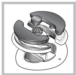
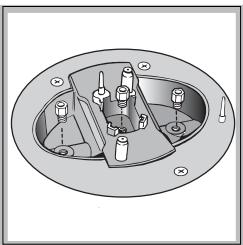
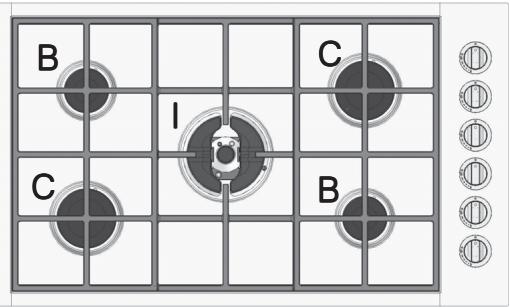
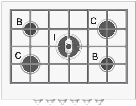
Replacing the "independent double flame" burner nozzles
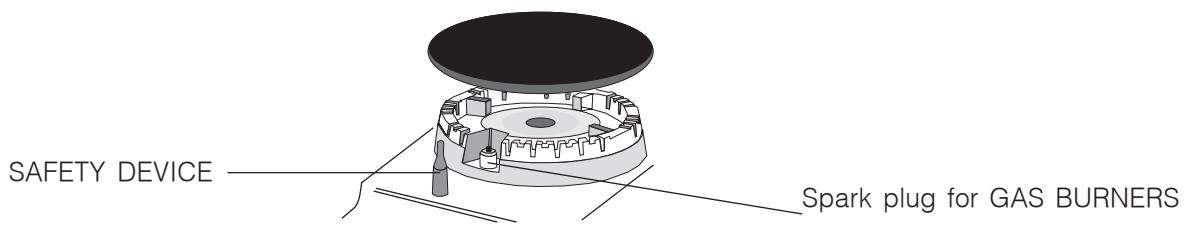
- Remove the hob grids and slide the burners off their seats. The burner consists of two separate parts (see Figures).
- Unscrew the nozzles using a 7 mm socket spanner. The inner burner has one nozzle and the outer burner has two (these are the same size). Replace the nozzles with models which are suitable for use with the new type of gas (Table 1).
- Replace all the components by following the above instructions in reverse.
- Adjusting the burners' primary air The burners do not require primary air adjustment.
-
Setting the burners to minimum
-
Turn the tap to its minimum setting position.
- Remove the knob and adjust the adjustment screw, which is positioned in or next to the tap pin, until the flame is small but steady.
- Having adjusted the flame to the required low setting, while the burner is alight, quickly change the position of the knob from minimum to maximum and vice versa several times, making sure that the flame is not extinguished.
- Some appliances have a safety device (thermocouple) fitted. If the device fails to work when the burners are set to the low flame setting, increase this low flame setting using the adjustment screw.
- Once the adjustment has been made, replace the seals on the by-passes using sealing wax or a similar substance.
! If the appliance is connected to liquid gas, the adjustment screw must be fastened as tightly as possible.
!Once this procedure is complete, replace the old rating sticker with one indicating the new type of gas used. Stickers are available from any of our Technical Assistance Centres.
! If the gas pressure used is different (or varies slightly) from the recommended pressure, a suitable pressure regulator must be fitted to the inlet pipe (in order to comply with current national regulations relating to "regulators for channelled gas").
| DATA PLATE | |
| Electrical connections | see data plate |
| CE | This appliance conforms to the following European Economic Community directives: -2006/95/EEC dated 12/12/06 (Low Voltage) and subsequent amendments -2004/108/EEC dated 15/12/04 (Electromagnetic Compatibility) and subsequent amendments -93/68/EEC dated 22/07/93 and subsequent amendments. -2009/142/EEC dated 30/11/09 (Gas) and subsequent amendments. -2002/96/EC and subsequent amendments. |
Burner and nozzle specifications
| Table 1 | Liquid gas | Natural gas | |||||||
| Burner | Diameter (mm) | Heating power kW (H.s.*) | By-pass 1/100 (mm) | Nozzle 1/100 (mm) | Flow rate * g/h | Nozzle 1/100 (mm) | Flow rate * l/h G20 | ||
| Nomin. | Red. | G30 | G31 | ||||||
| D. Triple ring | 130 | 3.25 | 1.3 | 57 | 91 | 236 | 232 | 124 | 309 |
| C. Rapid | 100 | 3.00 | 0.7 | 40 | 86 | 218 | 214 | 116 | 286 |
| B. Semi-rapid | 75 | 1.65 | 0.4 | 30 | 64 | 120 | 118 | 96 | 157 |
| I. Double flame (inner DC-DR) | 30 | 0.90 | 0.4 | 30 | 44 | 65 | 64 | 70 | 86 |
| I. Double flame (outer DC-DR) | 130 | 4.10 | 1.3 | 57 | 70 | 298 | 293 | 110 | 390 |
| Supply pressure | Nominal (mbar) | 28-30 | 37 | 20 | |||||
| Minimum (mbar) | 20 | 25 | 17 | ||||||
| Maximum (mbar) | 35 | 45 | 25 | ||||||
- At 15°C and 1013 mbar - dry gas
** Propane P.C.S. = 50.37 MJ/kg
*** Butane P.C.S. = 49.47 MJ/kg
Natural P.C.S. = 37.78 MJ/m³
!The hob can only be installed above built-in ovens with a cooling ventilation system.
PP 40 TC F...
PP 40 TC SF...
B PP 40TC/CS...
B PP 40TC...
PP 40 DCDR F...
PP 40 DCDR SF...
B PP 40DCDR/CS...
B PP 40DCDR...
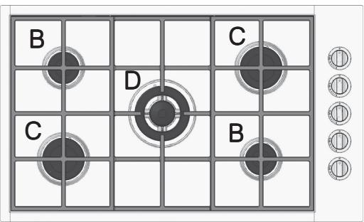
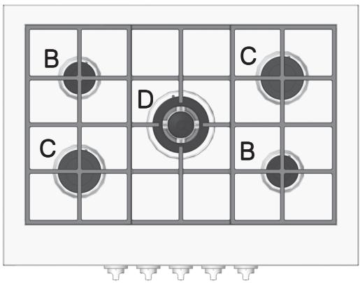
Description of the appliance
GB
Overall view
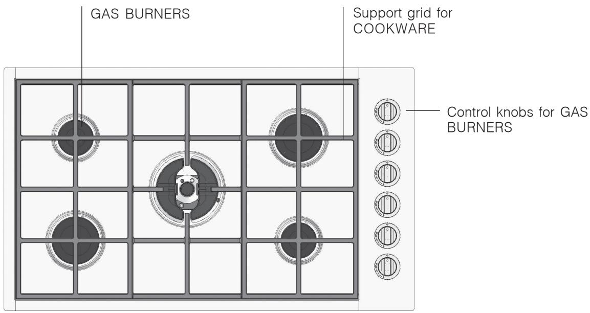
- GAS BURNERS vary in terms of size and power. Select the most suitable burner in accordance with the diameter of the cookware you wish to use.
- Control knobs for the GAS BURNERS adjust the flame or power setting.
- GAS BURNER ignition enables a specific burner to be lit automatically.
- SAFETY DEVICE: stops the gas flow if the flame is accidentally extinguished.
! The position of the corresponding gas burner or electric hotplate is shown on every knob.
Gas burners
Each burner can be adjusted to one of the following settings using the corresponding control knob:
0 Off
Maximum
Minimum
To light one of the burners, hold a lit match or lighter near the burner and, at the same time, press down and turn the corresponding knob anti-clockwise until it reaches the maximum setting.
For models fitted with a safety device, the knob should be held down for approximately 2-3 seconds, until the automatic device keeping the flame alight has heated up.
When using models with an ignition button, light the desired burner by pressing down the corresponding knob as far as possible and turning it anti-clockwise towards the maximum setting, keeping it pressed down until ignition has been achieved.
! Some models have a Double Flame burner. In this case, to activate it, simply start by turning the knob so that it is aligned with the symbol, then press it all the way in and hold it in this position for approximately 6 seconds, until the automatic device keeping the flame alight has heated up.
! If the burner flame is accidentally extinguished, shut off the control knob and wait for at least one minute before attempting to light the burner again.
To switch off the burner, turn the knob in a clockwise direction until it stops (position marked by the "0" symbol).
The "independent double flame" burner:
This gas burner consists of two concentric flame rings which can be used together or independently of each other. Using both simultaneously at maximum power makes it possible to reach a higher overall power level, thus reducing cooking time with respect to the time required by traditional burners. The double flame ring also distributes heat more evenly across the base of the pan, especially when both burners are set to the minimum power level. To ensure that the double-flame burner is used to its full potential, never set the inside ring to minimum and the outside ring to maximum at the same time. Cookware of all sizes may be used; when cooking with small recipients use only the inner burner. Each individual ring with an "independent double flame burner" has its own control knob:
the knob marked with the symbol controls the outer ring;
the knob marked with the symbol controls the inner ring.
To light the desired ring, press the corresponding knob fully in and turn it in an anticlockwise direction until it reaches the maximum power position. The burner is equipped with an electronic lighting system which is activated automatically when the knob is pressed.
As the burner is fitted with a safety device, the knob should be held down for approximately 2-3 seconds, until the automatic device keeping the flame alight has heated up.
Each burner can be adjusted to one of the following settings using the corresponding control knob: 0 Off
Maximum
Minimum
To switch off the burner, turn the knob in a clockwise direction until it stops (position marked by the "0" symbol).
Practical advice on using the burners
To ensure the burners operate efficiently:
- Use cookware which is suited to each burner (see table) in order to prevent the flames from extending beyond the base of the pans.
- Always use cookware with a flat base and a cover.
- When the contents of the pan reach boiling point, turn the knob to the minimum setting.
| Burner | Ø Cookware diameter (cm) |
| B. Semi-rapid | 12 – 22 |
| C. Rapid | 21 – 26 |
| D. Triple ring | 24 - 26 |
| I. DC-DR (inner) | 10 - 14 |
| I. DC-DR (outer) | 24 - 28 |
! For models equipped with a reducer grid, the latter must be used only for the inner Double Flame burner (inner DCDR), when pans with a diameter of less than 12 cm are used.
! Make sure the pans do not overlap the edges of the hob while it is being used.
! This appliance was designed and manufactured in compliance with international safety standards. The following warnings are provided for safety reasons and must be read carefully.
General safety
- This is a built-in appliance:
- Class 1: all models with edges that are higher than 77 / 87*mm (see Fig. 2, detail H3).
- Class 3: all models with edges that are higher than <77/87*mm (see Fig. 2, details H1 and H2).
- Gas appliances require regular air exchange in order to maintain efficient operation. When installing the hob, follow the instructions provided in the paragraph relating to "Positioning" the appliance.
- These instructions are only valid for the countries whose symbols appear in the manual and on the serial number plate.
- The appliance was designed for domestic use inside the home and is not intended for commercial or industrial use.
- The appliance must not be installed outdoors, even in covered areas. It is extremely dangerous to leave the appliance exposed to rain and storms.
- Do not touch the appliance when barefoot or with wet or damp hands and feet.
- The appliance must be used by adults only for the preparation of food, in accordance with the instructions provided in this booklet. Any other purpose (for example, heating the room) constitutes improper use of the oven and is dangerous. The manufacturer may not be held responsible for any damage caused as a result of improper, incorrect and unreasonable use of the appliance.
- Make sure that the power supply cables of other electrical appliances do not come into contact with the hot parts of the oven.
- The openings used for ventilation and heat dispersal must never be covered.
Always make sure the knobs are in the "0" position when the appliance is not in use. - When unplugging the appliance, always pull the plug from the mains socket; do not pull on the cable.
- Never perform any cleaning or maintenance work without having disconnected the appliance from the electricity mains.
- If the appliance breaks down, under no circumstances should you attempt to perform the repairs yourself. Repairs carried out by inexperienced individuals may cause injury or further malfunctioning of the appliance. Contact an authorised Service Centre (see Assistance).
- Always make sure that pan handles are turned towards the centre of the hob in order to avoid accidental burns.
-
Do not close the glass cover (if present) while the gas burners or electric hotplates are still hot.
-
Do not use unstable or warped pans.
- As it is a potential hazard, make sure that children and disabled individuals do not have access to the glass ceramic cooking zones (if present) during and immediately after cooking, as these zones remain hot for at least half an hour after they have been switched off.
- If the glass ceramic surface breaks, please contact any assistance centre which has been authorised by the manufacturer.
- If the glass ceramic surface breaks, it is best to disconnect the appliance from the electricity supply.
- Remove any liquids on the cover before opening it.
- Do not let children play with the appliance.
- The appliance should not be operated by people (including children) with reduced physical, sensory or mental capacities, by inexperienced individuals or by anyone who is not familiar with the product. These individuals should, at the very least, be supervised by someone who assumes responsibility for their safety or receive preliminary instructions relating to the operation of the appliance.
- The conditions relating to the adjustment procedure are listed on the label (or on the data plate); before installing the product, make sure the local supply conditions and the adjustment status are compatible.
- Intensive and prolonged operation of the appliance may require additional ventilation, for example a window should be opened or more efficient ventilation provided (the power of any mechanical ventilation system could be increased, for instance).
- The appliance is not intended to be operated by means of an external timer or separate remote-control system.
Disposal
- When disposing of packaging material: observe local legislation so that the packaging may be reused.
- The European Directive 2002/96/EC relating to Waste Electrical and Electronic Equipment (WEEE) states that household appliances should not be disposed of using the normal solid urban waste cycle. Exhausted appliances should be collected separately in order to optimise the cost of re-using and recycling the materials inside the machine, while preventing potential damage to the atmosphere and to public health. The crossed-out dustbin is marked on all products to remind the owner of their obligations regarding separated waste collection. Exhausted appliances may be collected by the public waste collection service, taken to suitable collection areas in the area or, if permitted by current national legislation, they may be returned to the dealers as part of an exchange deal for a new equivalent product. All major manufacturers of household appliances participate in the creation and organisation of systems for the collection and disposal of old and disused appliances.
Switching the appliance off
Disconnect your appliance from the electricity supply before carrying out any work on it.
Cleaning the appliance
! Do not use abrasive or corrosive detergents such as stain removers, anti-rust products, powder detergents or sponges with abrasive surfaces: these may scratch the surface beyond repair.
! Never use steam cleaners or pressure cleaners on the appliance.
- It is usually sufficient simply to wash the hob using a damp sponge and dry it with absorbent kitchen towel.
- The removable parts of the burner should be washed regularly with warm water and soap, ensuring any stubborn residue is removed.
- For hobs which light automatically, the terminal part of the electronic instant lighting devices should be cleaned frequently and the gas outlet holes should be checked for blockages.
- Stainless steel can be marked by hard water that has been left on the surface for a long time, or by aggressive detergents containing phosphorus. After cleaning, rinse well and dry thoroughly. Any remaining drops of water should also be dried.
Gas tap maintenance
Over time, the taps may become jammed or difficult to turn. If this occurs, the tap must be replaced.
! This procedure must be performed by a qualified technician who has been authorised by the manufacturer.
It may happen that the appliance does not function properly or at all. Before calling the service centre for assistance, check if anything can be done. First check to see that there are no interruptions in the gas and electrical supplies, and, in particular, that the gas taps for the mains supply are open.
Problem
The burner does not light or the flame is not even.
The flame does not remain lit in models with a safety device.
The burner does not remain lit when set to minimum.
The cookware is unstable.
Possible causes / Solutions:
- The gas holes on the burner are clogged.
- All the movable parts that make up the burner are assembled correctly.
-
There are draughts near the appliance.
-
The knob has not been pressed all the way in.
- The knob has not been pressed in long enough to activate the safety device.
-
The gas holes aligned with the safety device are blocked.
-
The gas holes are blocked.
-
There are draughts near the appliance.
-
The minimum setting has not been adjusted properly.
-
The bottom of the cookware is perfectly flat.
- The cookware is positioned correctly at the centre of the burner.
- The pan support grids have been positioned incorrectly.
If, despite all these checks, the hob does not function properly and the problem persists, contact your nearest Technical Assistance Centre. Please have the following information to hand:
- The appliance model (Mod.).
- The serial number (S/N).
This information can be found on the data plate located on the appliance and/or on the packaging.
! Never use the services of unauthorised technicians and never accept spare parts which are not original.
FR

Italiano, 1

English, 13

Français, 25

Deutsch, 37

Nederlands, 49

Espanol, 61
PP 40 DCDR F...
PP 40 DCDR SF...
PP 40 TC F...
PP 40 TC SF...
B PP 40DCDR/CS...
B PP 40DCDR...
B PP 40TC/CS...
B PP 40TC...
Sommaire
Installation, 26-31
Positionnement

- Description of the appliance, 20
- Start-up and use, 21
- Precautions and tips, 22
- Care and maintenance, 23
- Positioning
- Built-in appliance
- Installing sit-on hobs
- Fitting the hob to the cabinet
- FOR MODELS: PP 40 DCDRF ... - PP 40 TCF
- To fit this type of hob, follow the instructions below (Fig. 5):
- FOR MODELS: PP 40 DCDR SF... - PP 40 TC SF...
- Electrical connection
- Connecting the power supply cable to the electricity mains
- Gas connection
- Connection with a rigid pipe (copper or steel)
- Connecting a flexible jointless stainless steel pipe to a threaded attachment
- Checking the tightness of the connection
- Adapting to different types of gas
- Replacing the "independent double flame" burner nozzles
- Burner and nozzle specifications
- Description of the appliance
- Gas burners
- The "independent double flame" burner:
- Practical advice on using the burners
- General safety
- Disposal
- Switching the appliance off
- Cleaning the appliance
- Gas tap maintenance
- Problem
- Possible causes / Solutions:
- Sommaire
- Installation, 26-31
Brand : SCHOLTES
Model : PP 40 DCDR F
Category : Cooker