
MCF-LW13MIO - Smart Home MCF88 - Free user manual and instructions
Find the device manual for free MCF-LW13MIO MCF88 in PDF.


| Product Type | Smart Home Device |
| Model | MCF-LW13MIO |
| Brand | MCF88 |
| Dimensions (approximate) | 120 x 80 x 30 mm |
| Weight (approximate) | 150 g |
| Power Supply | DC 5V, 1A (USB) |
| Main Functions | Voice control, remote control via app, scheduling, scene modes, compatibility with Alexa and Google Assistant |
| Connectivity | Wi-Fi 2.4 GHz, Bluetooth 4.2 |
| Range | Up to 30 meters in open space (Wi-Fi dependent) |
| Sensors | Temperature, humidity, motion (optional) |
| Control Interface | Touch panel, smartphone app, voice commands |
| Compatibility | iOS and Android smartphones |
| Cleaning and Maintenance | Wipe with a dry, soft cloth. Do not use liquids or solvents. |
| Safety Features | Overload protection, fire-resistant plastic casing, automatic shutdown after 24 hours of inactivity |
| Operating Temperature | 0°C to 40°C |
| Humidity Range | 10% to 90% non-condensing |
| Spare Parts Availability | Common parts such as USB cables and adapters are widely available. Specific internal components may require contacting support. |
| Repairability | Moderate; user-replaceable fuse and battery (if applicable). Advanced repairs recommended for professionals. |
| Included Accessories | USB cable, user manual, mounting brackets (if applicable) |
| Warranty | 1 year limited warranty |
Frequently Asked Questions - MCF-LW13MIO MCF88
User questions about MCF-LW13MIO MCF88
0 question about this device. Answer the ones you know or ask your own.
Ask a new question about this device
Download the instructions for your Smart Home in PDF format for free! Find your manual MCF-LW13MIO - MCF88 and take your electronic device back in hand. On this page are published all the documents necessary for the use of your device. MCF-LW13MIO by MCF88.
USER MANUAL MCF-LW13MIO MCF88
MCF-LW13MIO is a LoRaWAN™ multi I/O module actuator with 16 opto-isolated AC/DC inputs and 8 relay outputs.

2. CONNECTION OF THE DEVICE
2.1 Power supply
Connect the power supply to pins 11 and 12 of J3.
Valid range is 24Vac/dc ± 10%
2.2 Digital inputs
| Type | Optoisolated |
| Rated operating voltage | 12÷24Vac/dc |
| OFF voltage | 0÷2 Vac/dc |
| ON voltage | 5 ÷ 28 Vac/dc |
| Input current | 30mA@12Vdc / 66mA@24Vdc |
In case of DC input, the positive terminal must be connected to the positive input.
| Connector | Pin | Name | Desciption |
| J1 | 1 | I+1 | Digital input 1 positive |
| 2 | I-1 | Digital input 1 negative | |
| 3 | I+2 | Digital input 2 positive | |
| 4 | I-2 | Digital input 2 negative | |
| 5 | I+3 | Digital input 3 positive | |
| 6 | I-3 | Digital input 3 negative | |
| 7 | I+4 | Digital input 4 positive | |
| 8 | I-4 | Digital input 4 negative | |
| 9 | I+5 | Digital input 5 positive | |
| 10 | I-5 | Digital input 5 negative | |
| 11 | I+6 | Digital input 6 positive | |
| 12 | I-6 | Digital input 6 negative |
| Connector | Pin | Name | Desciption |
| J2 | 1 | I+7 | Digital input 7 positive |
| 2 | I-7 | Digital input 7 negative | |
| 3 | I+8 | Digital input 8 positive | |
| 4 | I-8 | Digital input 8 negative | |
| 5 | I+9 | Digital input 9 positive | |
| 6 | I-9 | Digital input 9 negative | |
| 7 | I+10 | Digital input 10 positive | |
| 8 | I-10 | Digital input 10 negative | |
| 9 | I+11 | Digital input 11 positive | |
| 10 | I-11 | Digital input 11 negative | |
| 11 | I+12 | Digital input 12 positive | |
| 12 | I-12 | Digital input 12 negative |
| Connector | Pin | Name | Desciption |
| J3 | 1 | I+13 | Digital input 13 positive |
| 2 | I-13 | Digital input 13 negative | |
| 3 | I+14 | Digital input 14 positive | |
| 4 | I-14 | Digital input 14 negative | |
| 5 | I+15 | Digital input 15 positive | |
| 6 | I-15 | Digital input 15 negative | |
| 7 | I+16 | Digital input 16 positive | |
| 8 | I-16 | Digital input 16 negative | |
| 9 | VSS | VSS | |
| 10 | VSS | VSS | |
| 11 | Vac1 | Power supply | |
| 12 | Vac2 | Power supply |
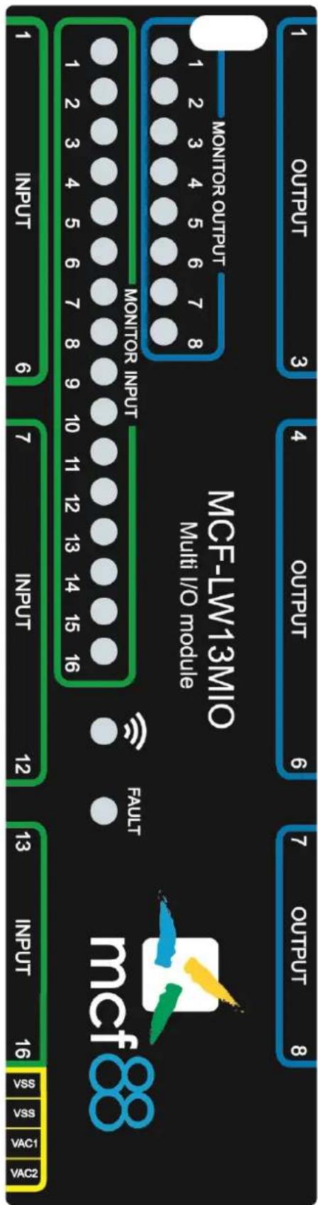
2.3 Digital outputs:
| Contact mode | SPDT |
| Max. power commutable | 1250VA |
| Maximum switching voltage | 250Vac |
| Minimum switching load mW | 500mW (10V/5mA) |
| Min. Number of operation | 100.000 |
| Max. current | 5A |
If driving an inductive load in AC, a Snubber must be provided in parallel to the contacts formed by a RC resistance network = 100Ohm 2w in series with a 100nF 400Volt polyester capacitor. In the case of a DC-controlled load, an anti-parallel diode must be placed on the load (ex. 1N4007). Each line must be protected with a suitable fuse (FUSE).

| Connector | Pin | Name | Desciption |
| J4 | 1 | NC_1 | Normally closed 1 |
| 2 | COM_1 | Common output 1 | |
| 3 | NO_1 | Normally open 1 | |
| 4 | NC_2 | Normally closed 2 | |
| 5 | COM_2 | Common output 2 | |
| 6 | NO_2 | Normally open 2 | |
| 7 | NC_3 | Normally closed 3 | |
| 8 | COM3 | Common output 3 | |
| 9 | NO_3 | Normally open 3 |
| Connector | Pin | Name | Desciption |
| J5 | 1 | NC_4 | Normally closed 4 |
| 2 | COM_4 | Common output 4 | |
| 3 | NO_4 | Normally open 4 | |
| 4 | NC_5 | Normally closed 5 | |
| 5 | COM_5 | Common output 5 | |
| 6 | NO_5 | Normally open 5 | |
| 7 | NC_6 | Normally closed 6 | |
| 8 | COM6 | Common output 6 | |
| 9 | NO_6 | Normally open 6 |
| Connector | Pin | Name | Desciption |
| J6 | 1 | NC_7 | Normally closed 7 |
| 2 | COM_7 | Common output 7 | |
| 3 | NO_7 | Normally open 7 | |
| 4 | NC_8 | Normally closed 8 | |
| 5 | COM_8 | Common output 8 | |
| 6 | NO_8 | Normally open 8 |
3. LORAWAN™ ACTIVATION
The device supports the following activations on a LoRaWAN ™ network:
NONE: sensor not activated
OTAA: needs settings of appkey and appEUI
OTAA MCF88: Over the air activation according to mcf88 specifications
ABP: needs settings of NwkSkey, AppSkey, DevAddr
The device exits factory activated with NONE mode. The devEUI of the device is shown on the product label.
MCF-LW13MIO is a Class C LoRaWAN TM device.
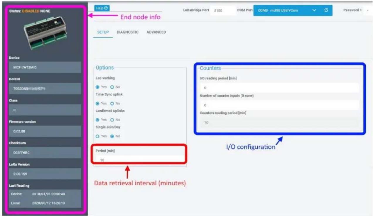
4. DEVICE CONFIGURATION
The activation parameters and the device settings can be read and modified via USB using the appropriate "LoRaWEB" desktop application (https://iot.mcf88.cloud/LoRaWeb/#/configuration):
LoRaWAN® Parameters
![LoRaWAN® Network Key App Key Device Address AppEUI DevEUI 70B 3D 5G 6G 7G 8G 9G 10G 11G LoRa Band Europe EU [868 MHz] LoRaWAN® Activation NONE OTAA MCF88 OTAA ABP Carrier Any Objenious Network Public Network Private Network](/content/2026/06/1340684/images/bbd6176cbdfca1829701d122133d8521d6d6801f6778e8c344a754ff60a8f6f4.jpg)
Road
Save File
Cancel
Save LoRaWAN® parameters
← → C iot.mcf83.cloud/LoRaWeb/#/configuration

Setup Download Resources Info Request offer
5. INSTALLATION
The magnetic antenna must be positioned on a metal body. It should preferably be vertical and at least 30 cm away from other metal bodies.

The installation must take place in a place where the LoRaWAN ™ signal coverage is good (SF=7 optimal, SF=12 weak).
6. ORDERING CODE
| Ordering Code | Description |
| MCF-LW13MIO | L0RaWAN Multi I/O module EU863-870 |
| MCF-LW13MIO-AS | LoRaWAN Multi I/O moduleAS923 |

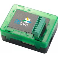
Brand : MCF88
Model : MCF-LW13MIO
Category : Smart Home