MCF-LW06424D - Home Automation MCF88 - Free user manual and instructions
Find the device manual for free MCF-LW06424D MCF88 in PDF.


| Product Type | Smart Home Automation Hub |
| Brand | MCF88 |
| Model | MCF-LW06424D |
| Dimensions (L x W x H) | 90 x 90 x 28 mm |
| Weight | 120 g |
| Power Supply | AC 100-240V, 50/60Hz |
| Max Power Load | 10A (2200W) |
| Wireless Connectivity | Wi-Fi 2.4GHz, Zigbee |
| Smart Assistant Compatibility | Amazon Alexa, Google Assistant |
| App Control | MCF88 Home app (iOS & Android) |
| Voice Control | Yes, via Alexa & Google Assistant |
| Remote Access | Yes, via cloud |
| Scheduling | Yes, timer and countdown |
| Energy Monitoring | Real-time power consumption |
| Operating Temperature | -10°C to 40°C |
| Housing Material | Fire-resistant PC/ABS |
| Safety Certifications | CE, RoHS |
| Maintenance | Wipe with dry cloth, do not use liquids |
| Spare Parts | Not user-serviceable; contact support |
| Warranty | 2 years |
| Package Contents | Hub, user manual, quick start guide |
Frequently Asked Questions - MCF-LW06424D MCF88
User questions about MCF-LW06424D MCF88
0 question about this device. Answer the ones you know or ask your own.
Ask a new question about this device
Download the instructions for your Home Automation in PDF format for free! Find your manual MCF-LW06424D - MCF88 and take your electronic device back in hand. On this page are published all the documents necessary for the use of your device. MCF-LW06424D by MCF88.
USER MANUAL MCF-LW06424D MCF88
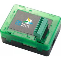
MCF-LW06424D is a class A LoRaWAN interface, ables to read 4 analog inputs 4-20mA with a resolution of 12 bit. Inputs have an insulation of 1000Vdc with respect to the power supply, and are protected against polarity inversion. It has a protected digital output to drive a load 24Vac/dc up to 500mA, useful for power the connected sensors only when making the measurement, and save energy.
MCF-LW06424D is available with an optional DIN rail mount board (MCF-DIN105) as follow:

2. CONNECTION OF THE DEVICE
2.1 Connection as stand-alone device:

| Pin | Name | Description |
| J3.7 | IO5 | Digital output positive (yellow) |
| J3.8 | IO6 | Digital output negative (white) |
| J3.9 | GND | Negative power supply (black) |
| J3.10 | VDD | Positive power supply range [10-36Vdc] (red) |
Power can also be supplied by USB.
2.2 Connection with MCF-DIN105:

2.2.1 Digital output:
| Pin | Name | Description |
| J1.1 | ||
| J1.2 | ||
| J1.3 | ||
| J1.4 | ||
| J1.5 | ||
| J1.6 | ||
| J1.7 | IO5 | Digital output positive |
| J1.8 | IO6 | Digital output negative |
Maximum load voltage: 26Vac/34Vdc Maximum load current: 500mA.
2.2.2 Power supply:
| Pin | Name | Description |
| J2.1 | VDD | Positive power supply range [10-36Vdc] |
| J2.2 | GND | Negative power supply |
Power can also be supplied by USB.
2.3 Analog inputs

| Pin | Name | Descriprion | Range | Resolution |
| J1.1 | AI1 | Analog input 1 | 4-20mA | 12 bit |
| J1.2 | GA | Common | ||
| J1.3 | AI2 | Analog input 2 | 4-20mA | 12 bit |
| J1.4 | GA | Common | ||
| J1.5 | AI3 | Analog input 3 | 4-20mA | 12 bit |
| J1.6 | GA | Common | ||
| J1.7 | AI4 | Analog input 4 | 4-20mA | 12 bit |
| J1.8 | GA | Common |
| Current Loop (4-20mA) | |
| Input resistance | 125Ω |
| Absolute maximum value | 24mA |
| Max error | ±0.1% |
| Insulation | 1000Vdc |
Current values less than 3mA generate a "disconnected sensor" condition.
Caution: inputs are not galvanically isolated from each other.
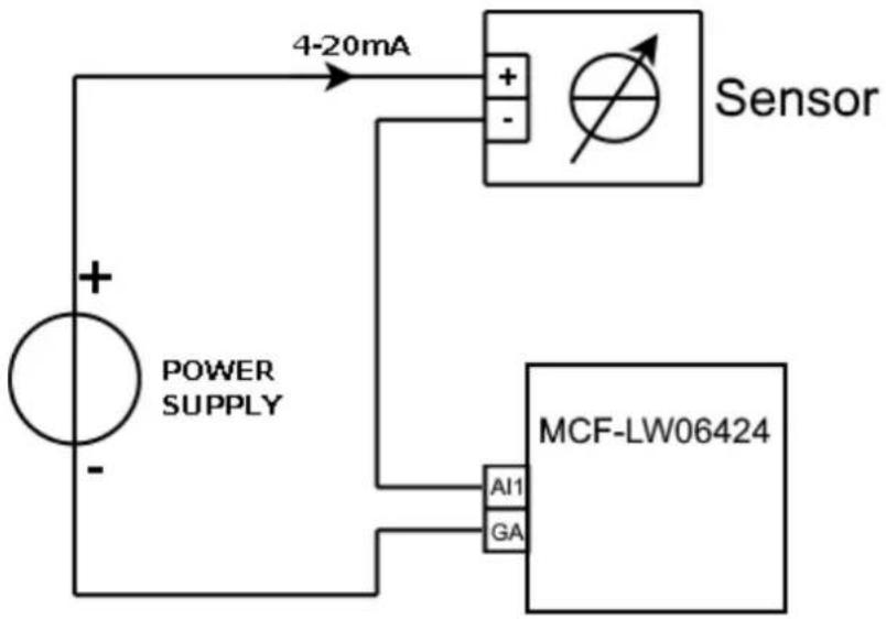
Connection examples for current inputs:
- 1 sensor
- 2 sensors
![graph TD A["Power Supply"] --> B["Measurement Device 1"] A --> C["Measurement Device 2"] B --> D["4-20mA Current Path"] C --> E["4-20mA Current Path"] D --> F["MCF-LW06424 Module"] E --> F style A fill:#f9f,stroke:#333 style B fill:#ccf,stroke:#333 style C fill:#ccf,stroke:#333 style D fill:#dfd,str…](/content/2026/05/1081986/images/c5836c09908e3e45308dbdb8c5ee8d7865df3d5dc8b3c20e0de49997069dd211.jpg)
2.4 Connect the antenna as shown below, using the provided clip to hold the antenna connector in place:

3. LORAWAN™ ACTIVATION
The device supports the following activations on a LoRaWAN ™ network:
NONE: sensor not activated
OTAA: needs settings of appkey and appEUI
OTAA MCF88: Over the air activation according to mcf88 specifications
ABP: needs settings of NwkSkey, AppSkey, DevAddr
The device exits factory activated with NONE mode. The devEUI of the device is shown on the product label. MCF-LW06420D is a Class A LoRaWAN ™ device.
4. DEVICE CONFIGURATION
The activation parameters and the device settings can be read and modified via USB using the appropriate "LoRaWEB" desktop application (https://iot.mcf88.cloud/LoRaWeb/#/configuration):
LoRaWAN® Parameters
×
![LoRaWAN® Network Key App Key Device Address AppEUI DevEUI 70B3D 589102024 LoRa Band Europe EU [868 MHz] LoRaWAN® Activation NONE OTAA MCF88 OTAA ABP Carrier Any Objurious Network Public Network Private Network](/content/2026/05/1081986/images/540d912455f2efe1d75d5f80b4ad7c4ee8b3e829a35a775b50885a26e8b90212.jpg)
Read
Save File
Cancel
Save LoRaWAN® parameters

5. INSTALLATION
The magnetic antenna must be positioned on a metal body. It should preferably be vertical and at least 30 cm away from other metal bodies.
The installation must take place in a place where the LoRaWAN ™ signal coverage is good (SF=7 optimal, SF=12 weak).
6. ORDERING CODE
| Ordering Code | Description |
| MCF-LW06424D | 4-20mA to LoRaWAN interface with DO EU863-870 |
| MCF-LW06424D-AS | 4-20mA to LoRaWAN interface with DO AS923 |
| MCF-DIN105 | DIN Rail option 105mm |


Brand : MCF88
Model : MCF-LW06424D
Category : Home Automation