
Farum - Fireplace FABER - Free user manual and instructions
Find the device manual for free Farum FABER in PDF.
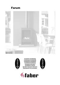


| Product Type | Wood-burning Fireplace |
| Brand | Faber |
| Model | Farum |
| Fuel Type | Wood logs |
| Heat Output | Approximately 12 kW |
| Efficiency | Up to 80% |
| Dimensions (H x W x D) | 1200 x 800 x 600 mm |
| Weight | 180 kg |
| Flue Outlet Diameter | 200 mm (top or rear) |
| Material | Steel and cast iron |
| Door Type | Single glass door with self-cleaning air wash |
| Primary Air Control | Manual slide control |
| Secondary Air Control | Adjustable for optimum combustion |
| Ash Pan | Removable for easy cleaning |
| Certification | CE, EN 13240 |
| Installation Type | Freestanding or built-in |
| Maintenance | Regular cleaning of glass and ash removal; annual chimney sweep recommended |
| Warranty | 5 years on combustion chamber |
Frequently Asked Questions - Farum FABER
User questions about Farum FABER
0 question about this device. Answer the ones you know or ask your own.
Ask a new question about this device
Download the instructions for your Fireplace in PDF format for free! Find your manual Farum - FABER and take your electronic device back in hand. On this page are published all the documents necessary for the use of your device. Farum by FABER.
USER MANUAL Farum FABER
40011116-1114
NL
NO
DK
DE
CZ
ENG
HU


1.1

2.1

2.2

2.3

3.1

3.2

3.3

3.4

4.1

4.2


1 NL....5 2 NO 12 3 DK....19 4 DE....26 5 CZ....33 6 ENG....40 7 HU 47 8 RU 54
1 NL
1.1 Introduction
C + E = 1 + 1 2 m
D = 1 × 2 m 2 m
4m
Add the vertical lengths
A 1 m
G 1 m
2 m

Calculation example 2
Add the horizontal lengths
J + L = 0.5 + 0.5 = 1 m
K + M = 2 + 2 = 4 m
N 1 m

Total vertical lengths
H 1 m

1 m

1.12.2 Flow table
C + E = 1 + 1 = 2 m
D = 1 × 2 = 2 m
Total 4 m
J + L = 0.5 + 0.5 = 1 m
K + M = 2 + 2 = 4 m
1 m
2.12 Table
Find the correct number of vertical and horizontal lengths in the table.
3.12 Table
C + E = 1 + 1 2 m
D = 1 × 2 m 2 m
4 m
J + L = 0, 5 + 0, 5 1 m
K + M = 2 + 2 m 4 m
N = 1 m
6 m
5.12 Table
The appliance can only be installed by a competent person in accordance with the Gas Safety. We urgently advise you to read this installation manual properly.
This appliance complies with the guidelines for European gas appliances (Gas Appliances Directive) and bears the CE mark.
6.2 Safety instructions.
- The appliance should be placed, connected and annually checked in accordance with these installation instructions and valid national and local Gas Safety (Installation and Use) Regulations.
- Check whether the data on the registration plate are in agreement with the local type of domestic gas and pressure.
- The fitter is not permitted to change these adjustments or the construction of the appliance!
- Do not place any additional imitation logs or glowing coals on the burner or in the combustion chamber.
- The appliance has been designed for ambience and heating purposes. This means that all surfaces of the appliance, including the glass, can become very hot (hotter than 100 °C). An exception to this are the bottom of the appliance and the controls.
- Do not place any inflammable materials within a distance of 0.5 m from the radiation of the appliance and ventilation grills.
- Due to natural air circulation of the appliance, moisture and volatile components from paint, building materials, floor coverings etc. that haven't yet set, can be drawn through the convection system and can be deposited on cold surfaces as soot. That is why you should not use the appliance shortly after a renovation.
- The first time the appliance is switched on, let the fire run on maximum setting for several hours so that the lacquer coating will have an opportunity to set and possible vapours released can be safely
removed by ventilation. We advise you to be outside the room as much as possible during this process!
- Please note that:
1 all transport packaging should be removed. 2 children or pets should not be present in the room.
6.3 Installation requirements
6.3.1 Minimum distance around the fire
Keep in mind that there has to be a minimal distance of 200 millimetres between the side glass of the appliance and a wall. At the backside there has to be a minimal distance of 80 millimetres.
6.3.2 Requirements flue system and outlets
- You should always make use of the materials prescribed by Faber International Ltd. Only by using these materials can Faber International Ltd. guarantee a proper functioning.
- The outside of the concentric flue material can reach a temperature of approx 150°C. Make sure of proper isolation and protection in case of transit through combustible wall or ceiling constructions. And observe sufficient distance.
- Make sure that the concentric flue materials are bracketed every 2 metres when they have an extended length, so that the weight of the flue material is not resting on the appliance itself.
- You may never start with a cut-down concentric pipe directly on to the appliance.
6.3.3 Terminals
The flue outlet can end on an external wall or a roof. Check whether the outlet desired by you complies with local requirements concerning good function and ventilation systems.
For proper functioning, the terminal should be at least 0.5 m away from:
- Corners of the building.
- Roof overhangs and balconies.
- Eaves (with the exception of the roof ridge).
6.3.4 Existing Chimney
You can also connect the appliance to an existing chimney. The existing chimney will function as an air supply and a flexible stainless steel pipe drawn up through the chimney will remove the combustion gas. The flexible stainless steel pipe of ∅ 100 mm should have a CE mark for temperatures up to 600° Celsius.
The chimney should comply with the following requirements:
- The diameter of the flue system must be at least 150x150 mm.
- There should be no more than 1 appliance connected to a flue pipe.
- The chimney must be in good condition.
- No leakage and
- It should be properly swept.
For more information about connections to existing flue systems, see the manual "Connections".
6.4 Preparation and Installation Instructions
6.4.1 Gas Connection
The gas connection must comply with locally valid standards.
We advise that pipe work from the meter to the appliance must be of adequate size, with a gas isolator tap near the appliance that should always be accessible. Place the gas connection in such a way that it is easily accessible, and that before service, the burner unit can be disconnected at all times.
6.4.2 Electric Connection
If an adapter is used for the power supply, then a wall socket 230VAC - 50Hz must be mounted in the close neighbourhood of the hearth.
6.4.3 Preparation of the Appliance
- Remove the packaging of the appliance. Make sure the gas pipes underneath the appliance are not damaged.
- Clear a safe space to store the frame and the glass.
- Remove the frame (if necessary) and the glass, and take the separately wrapped parts out of the appliance.
- Prepare the gas connection to the gas control valve.
6.4.4 Placing the Appliance
Take the installation requirements into account (see chapter 3).
6.4.5 Mounting the Smoke Emission Outlet Materials
- In case of a wall or roof terminal, the hole must be at least 5 mm bigger than the diameter of the flue material.
- Horizontal parts must be installed at a (3 degree) slope up away the appliance.
- Build up the system from the appliance. If this is not possible, you should make use of a adjustable pipe
- For fitting the system a 1/2 metre cut-down pipe should be used. Make sure the inner pipe is always 2 cm longer than the outer pipe. Wall and roof terminal are also shortened. These parts must be secured with a self tapping screw.
- Do not insulate but ventilate build-in flue material (approx.100cm2)
6.5 Removing the glass
- Place the suction discs onto the glass
- Remove the cover strips on the left and right hand side. (see fig. 2.1.)
- Remove the glass clips, by using a screwdriver. (see fig. 2.2.)
- Slide the glass upwards so that the bottom edge is released. Now gradually move the bottom edge of the glass forwards and lower the glass (see fig.2.3)
To replace the glass repeat the process in reverse order.
Remove all fingerprints from the glass, these will be burned into it once the appliance is used.
6.6 Placing the decorative material
It is not allowed to add different or more materials to the combustion chamber. Always keep the pilot burner free from decorative material!
6.6.1 Placing the imitation logs
- Place the imitation logs. Make sure that the logs are properly connected to the tube burners (see fig. 4.1 or the imitation logs instruction card supplied).
- Now divide the vermiculite pebbles and the chips in the combustion chamber. Avoid covering the air vent(s).
- Place the glass and check the fire image.
6.6.2 Pebbles
- Place the pebbles over the burner and the bottom. Spread the pebbles evenly to a double layer. The surface of the pebbles may be very slightly higher than the burner tube (see fig. 4.2).
- Place the glass and check the flame picture into the appliance.
6.7 Checking the installation.
6.7.1 Checking the ignition of the pilot burner and main burner.
Start the pilot and main burner according to the instructions in the user's manual.
- Check whether the pilot light is properly positioned above the main burner and is not covered by chips, an imitation log, or pebbles.
- Check the ignition of the main burner at full mark or low mark. (The ignition should take place quickly and easily.)
6.7.2 Checking for gas leakage.
Check all connections and joins for possible gas leaks by means of a gas leak detector or spray.
6.7.3 Checking the burner pressure and the pre-pressure.
Check whether the burner pressure and the inlet pressure measured agree with the data indicated on the registration plate.
Measuring the inlet-pressure:
- Turn off the gas control tap.
- Open the pressure gauge nipple A (see figure 1.1) a few turns and connect a pressure gauge hose to the gas control valve.
- Carry out this measurement when the appliance is on at full gas mark and when it is on the pilot light.
- If the inlet pressure is too high you are not permitted to connect the appliance.
Measuring the burner pressure:
Only perform this measurement if the inlet-pressure is correct.
- Open the pressure gauge nipple B (see fig. 1.1) a few turns and connect a pressure gauge hose to the gas control valve.
- The pressure must agree with the value indicated on the registration plate. In case of deviations, get in touch with the manufacturer.
* Close the pressure gauge nipples and check these for gas leaks.
6.7.4 Checking the flame picture.
Allow the appliance to burn for at least 20 minutes at full and then check the flame picture for:
- Distribution of the flames
- Colour of the flames
If either one or both points are unacceptable, then check:
- The positioning of the imitation logs and/or the quantity of pebbles or chips on the burner.
- The connections of the flue materials for leakage (in case of blue flames).
- Whether the correct flue restrictor has been mounted.
- The outlet: wall terminal is installed correctly.
- Roof terminal is fitted and sited correctly.
The flue system is correctly calculated.
6.8 Instructing the client
- Recommend that the appliance be serviced annually by a competent person in order to guarantee safe use and a long lifespan.
- Advise and instruct the client about maintenance and cleaning of the glass. Emphasize the risk of burning from fingerprints.
- Instruct the client about the operation of the appliance and the remote control unit, including the
replacement of the batteries and adjusting the receiver for initial use.
- Hand over to the client: • Installation manual
- User's manual
- Imitation logs instruction card • • Annual maintenance
6.9 Service and cleaning:
- Check and clean if necessary after checking:
- The pilot light
- The burner
- The combustion chamber
- The glass
- The logs for possible fractures
- The outlet
6.9.1 Replace:
○ If necessary the chips/embers.
6.9.2 Cleaning the glass
Most of the deposits can be removed with a dry cloth. You can use ceramic hob cleaner to clean the glass.
Note: prevent fingerprints on the glass. These will be burned into it once the appliance is used and cannot be removed anymore!
Carry out the check-up according to the instructions in chapter 7 “Checking the installation”.
6.10 Conversion to a different type of gas (e.g. propane)
This can only be done by installing the proper burner unit. For this purpose, get in touch with your supplier.
Always mention the type and serial number of the appliance when ordering.
6.11 Calculation of flue system
The possibilities for the lengths of flue pipes and the possible restrictors have been recorded in a table (see chapter 12). This table works with a vertical and a horizontal length.
- To define the vertical length, all lengths of flue pipes in a vertical direction should be added up.
- The roof terminal always counts as 1 metre.
- To define the horizontal length, all lengths of flue pipes in a horizontal direction should be added up.
- Every 90° bend in the horizontal part counts as 2 metres.
- Every 45° bend in the horizontal part counts as 1 metre.
- Turns from vertical to horizontal or vice versa are not reckoned in the calculation.
- The wall terminal always counts as 1 metre.
If there is transit under 45° then the real vertical and horizontal lengths should be calculated.
6.11.1 Points of particular interest:
- You should never start with a cut-down pipe from the appliance.
6.11.2 Sample computations
Sample calculation 1
Count the horizontal lengths
Flue pipe lengths C+E = 1 + 1 = 2 m
Bend D = 1 x 2 m = 2 m
Total 4 m
Count the vertical lengths
Flue pipe length A = 1 m
Roof terminal G
1 m
Total 2 m

Sample calculation 2
Count the horizontal lengths
Flue pipe lengths J + L = 0.5 + 0.5 = 1 m
Bends K + M = 2 + 2 = 4 m
Wall terminal 1 m
Total horizontal length 6 m
Count the vertical lengths
Flue pipe length H 1 m
Total 1 m

6.12 Table
Find the correct vertical and horizontal lengths in the table.
In case of an "x", or if the values are outside the table, the combination is not permitted.
The value found indicates the width of the restrictor to be placed (“0” means no restrictor should be placed).
Generally a 30mm restrictor is pre-installed
* When only a vertical flue length is used, then you must install the additional air restrictor under in the appliance (see fig 3.1 up to 3.4)
| Horizontaal | ||||||||
| 0 | 1 | 2 | 3 | 4 | 5 | 6 | ||
| Verticaal | 0 | x | x | x | x | x | x | x |
| 0.5 | x | 30 | x | x | x | x | x | |
| 1 | 30* | 30 | 30 | 0 | 0 | 0 | 0 | |
| 1.5 | 30* | 30 | 30 | 30 | 0 | 0 | 0 | |
| 2 | 30* | 40 | 30 | 30 | 30 | 0 | 0 | |
| 3 | 40* | 50 | 40 | 30 | 30 | 30 | 0 | |
| 4 | 50* | 50 | 50 | 40 | 30 | 30 | 30 | |
| 5 | 50* | 60 | 50 | 50 | 40 | 30 | 30 | |
| 6 | 60* | 60 | 60 | 50 | 50 | 40 | 30 | |
| 7 | 60* | 60 | 60 | 60 | 50 | 50 | x | |
| 8 | 60* | 65 | 60 | 60 | 60 | x | x | |
| 9 | 65* | 65 | 65 | 60 | x | x | x | |
| 10 | 65* | 65 | 65 | x | x | x | x | |
| 11 | 65* | 65 | x | x | x | x | x | |
| 12 | 65* | x | x | x | x | x | x | |
6.13 Technical data
| Gascat. | II2H3+ | II2H3+ | II2H3+ | |
| Type of Apliance | C11 C31 | C11 C31 | C11 C31 | |
| Reference gas | G20 | G30 | G31 | |
| Input Nett | kW | 4.5 | 4.2 | 4.2 |
| Efficiency class | 2 | 2 | 2 | |
| NOx class | 5 | 4 | 4 | |
| inlet-pressure | mbar | 20 | 30 | 37 |
| Gas rate at 15°C and 1013 mbar | l/h | 482 | 127 | 164 |
| Gas rate at 15°C and 1013 mbar | gr/h | 320 | 310 | |
| Burner pressure at full mark | mbar | 10 | 24,8 | 31,6 |
| Injector main burner | mm | 1.90 | 1.1 | 1.1 |
| Reduced input restraint | mm | 1.1 | 0.85 | 0.85 |
| Pilot assembly | OPNG9030 | OPLPG9222 | OPLPG9222 | |
| Code | - | - | - | |
| Diameter inlet / outlet | mm | 150-100 | 150-100 | 150-100 |
| Gas control valve | GV60 | GV60 | GV60 | |
| Gas connection | 3/8” | 3/8” | 3/8” | |
| Electrical connection | V | 220 | 220 | 220 |
| Batteries receiver | V | 4x1.5AA | 4x1.5AA | 4x1.5AA |
| Batteries sender | V | 9 | 9 | 9 |
7 HU
7.1 Introduction
C + E = 1 + 1 = 2 m
D = 1 × 2 = 2 m
Total 4 m
J + L = 0.5 + 0.5 = 1 m
K + M = 2 + 2 = 4 m
N = 1 m
Total 6 m

7.12 Table
8.12 Table

- NL
- INTRODUCTION
- CALCULATION EXAMPLE
- FLOW TABLE
- TABLE
- SAFETY INSTRUCTIONS
- INSTALLATION REQUIREMENTS
- MINIMUM DISTANCE AROUND THE FIRE
- REQUIREMENTS FLUE SYSTEM AND OUTLETS
- TERMINALS
- EXISTING CHIMNEY
- PREPARATION AND INSTALLATION INSTRUCTIONS
- GAS CONNECTION
- ELECTRIC CONNECTION
- PREPARATION OF THE APPLIANCE
- PLACING THE APPLIANCE
- MOUNTING THE SMOKE EMISSION OUTLET MATERIALS
- REMOVING THE GLASS
- PLACING THE DECORATIVE MATERIAL
- PLACING THE IMITATION LOGS
- PEBBLES
- CHECKING THE INSTALLATION
- CHECKING THE IGNITION OF THE PILOT BURNER AND MAIN BURNER
- CHECKING FOR GAS LEAKAGE
- CHECKING THE BURNER PRESSURE AND THE PRE-PRESSURE
- MEASURING THE INLET-PRESSURE
- MEASURING THE BURNER PRESSURE
- CHECKING THE FLAME PICTURE
- INSTRUCTING THE CLIENT
- SERVICE AND CLEANING
- REPLACE
- CLEANING THE GLASS
- CONVERSION TO A DIFFERENT TYPE OF GAS (E.G. PROPANE)
- CALCULATION OF FLUE SYSTEM
- POINTS OF PARTICULAR INTEREST
- SAMPLE COMPUTATIONS
- SAMPLE CALCULATION
- COUNT THE VERTICAL LENGTHS
- TECHNICAL DATA
- HU
Brand : FABER
Model : Farum
Category : Fireplace