
GT-10 - Guitar Multi-Effects ROLAND - Free user manual and instructions
Find the device manual for free GT-10 ROLAND in PDF.

| Product type | Multi-effects for guitar |
| Brand | Roland |
| Model | GT-10 |
| Dimensions (W x D x H) | 426 x 173 x 63 mm |
| Weight | 3,4 kg |
| Power supply | DC 9 V AC adapter (included) |
| Power consumption | 800 mA max |
| Number of effects | More than 70 |
| Amp modeling | COSM (Composite Object Sound Modeling) |
| A/D converter | 24 bits |
| Sampling frequency | 44,1 kHz |
| Expression pedal | Built-in (volume, wah control, etc.) |
| Inputs | 6.35 mm jack (guitar), AUX IN (3.5 mm jack) |
| Outputs | 6.35 mm jack (L/R), headphones (6.35 mm jack) |
| MIDI | In/Out (5-pin) |
| USB | Type B (PC connection) |
| Tuner function | Built-in chromatic tuner |
| Effects loop | Yes (send/return) |
| Display | Backlit LCD screen |
| Memory | 100 user patches + 100 presets |
| Maintenance and cleaning | Clean with a dry, soft cloth. Avoid solvents. |
| Safety | Do not expose to humidity or extreme temperatures. |
| Spare parts and repairability | Parts available from authorized Roland service centers. |
| General information | Complete manual downloadable from the Roland website. |
Frequently Asked Questions - GT-10 ROLAND
User questions about GT-10 ROLAND
0 question about this device. Answer the ones you know or ask your own.
Ask a new question about this device
Download the instructions for your Guitar Multi-Effects in PDF format for free! Find your manual GT-10 - ROLAND and take your electronic device back in hand. On this page are published all the documents necessary for the use of your device. GT-10 by ROLAND.
USER MANUAL GT-10 ROLAND
GT-10 GUITAR EFFECTS PROCESSOR
Owner's Manual
Thank you, and congratulations on your choice of the BOSS GT-10.
Before using this unit, carefully read the sections entitled: "USING THE UNIT SAFELY" (p. 2-3), and "IMPORTANT NOTES" (p. 4-5). These sections provide important information concerning the proper operation of the unit. Additionally, in order to feel assured that you have gained a good grasp of every feature provided by your new unit, Owner's manual should be read in its entirety. The manual should be saved and kept on hand as a convenient reference.
USING THE UNIT SAFELY
INSTRUCTIONS FOR THE PREVENTION OF FIRE, ELECTRIC SHOCK, OR INJURY TO PERSONS
About WARNING and CAUTION Notices
| ▲WARNING | Used for instructions intended to alert the user to the risk of death or severe injury should the unit be used improperly. |
| ▲CAUTION | Used for instructions intended to alert the user to the risk of injury or material damage should the unit be used improperly. * Material damage refers to damage or other adverse effects caused with respect to the home and all its furnishings, as well to domestic animals or pets. |
About the Symbols
| ▲ | The △ symbol alerts the user to important instructions or warnings. The specific meaning of the symbol is determined by the design contained within the triangle. In the case of the symbol at left, it is used for general cautions, warnings, or alerts to danger. |
| ◎ | The ⊙ symbol alerts the user to items that must never be carried out (are forbidden). The specific thing that must not be done is indicated by the design contained within the circle. In the case of the symbol at left, it means that the unit must never be disassembled. |
| ● | The ● symbol alerts the user to things that must be carried out. The specific thing that must be done is indicated by the design contained within the circle. In the case of the symbol at left, it means that the power-cord plug must be unplugged from the outlet. |
ALWAYS OBSERVE THE FOLLOWING
WARNING
- Do not open (or modify in any way) the unit or its AC adaptor.

- Do not attempt to repair the unit, or replace parts within it (except when this manual provides specific instructions directing you to do so). Refer all servicing to your retailer, the nearest Roland Service Center, or an authorized Roland distributor, as listed on the "Information" sheet.

-
Never use or store the unit in places that are:
-
Subject to temperature extremes (e.g., direct sunlight in an enclosed vehicle, near a heating duct, on top of heat-generating equipment); or are

- Damp (e.g., baths, washrooms, on wet floors); or are
- Humid; or are
- Exposed to rain; or are
- Dusty; or are
-
Subject to high levels of vibration.
-
Make sure you always have the unit placed so it is level and sure to remain stable. Never place it on stands that could wobble, or on inclined surfaces.

- Be sure to use only the AC adaptor supplied with the unit. Also, make sure the line voltage at the installation matches the input voltage specified on the AC adaptor's body. Other AC adaptors may use a different polarity, or be designed for a different voltage, so their use could result in damage, malfunction, or electric shock.
WARNING
- Use only the attached power-supply cord. Also, the supplied power cord must not be used with any other device.

- Do not excessively twist or bend the power cord, nor place heavy objects on it. Doing so can damage the cord, producing severed elements and short circuits. Damaged cords are fire and shock hazards!

- This unit, either alone or in combination with an amplifier and headphones or speakers, may be capable of producing sound levels that could cause permanent hearing loss. Do not operate for a long period of time at a high volume level, or at a level that is uncomfortable. If you experience any hearing loss or ringing in the ears, you should immediately stop using the unit, and consult an audiologist.

- Do not allow any objects (e.g., flammable material, coins, pins); or liquids of any kind (water, soft drinks, etc.) to penetrate the unit.


WARNING
-
Immediately turn the power off, remove the AC adaptor from the outlet, and request servicing by your retailer, the nearest Roland Service Center, or an authorized Roland distributor, as listed on the "Information" page when:
-
The AC adaptor, the power-supply cord, or the plug has been damaged; or
- If smoke or unusual odor occurs
- Objects have fallen into, or liquid has been spilled onto the unit; or
- The unit has been exposed to rain (or otherwise has become wet); or
-
The unit does not appear to operate normally or exhibits a marked change in performance.
-
In households with small children, an adult should provide supervision until the child is capable of following all the rules essential for the safe operation of the unit.

- Protect the unit from strong impact. (Do not drop it!)

-
Do not force the unit's power-supply cord to share an outlet with an unreasonable number of other devices. Be especially careful when using extension cords—the total power used by all devices you have connected to the extension cord's outlet must never exceed the power rating (watts/amperes) for the extension cord. Excessive loads can cause the insulation on the cord to heat up and eventually melt through.
-
Before using the unit in a foreign country, consult with your retailer, the nearest Roland Service Center, or an authorized Roland distributor, as listed on the "Information" sheet.

- The unit and the AC adaptor should be located so their location or position does not interfere with their proper ventilation.

- Always grasp only the plug on the AC adaptor cord when plugging into, or unplugging from, an outlet or this unit.

-
At regular intervals, you should unplug the AC adaptor and clean it by using a dry cloth to wipe all dust and other accumulations away from its prongs. Also, disconnect the power plug from the power outlet whenever the unit is to remain unused for an extended period of time. Any accumulation of dust between the power plug and the power outlet can result in poor insulation and lead to fire.
-
Try to prevent cords and cables from becoming entangled. Also, all cords and cables should be placed so they are out of the reach of children.

- Never climb on top of, nor place heavy objects on the unit.

- Never handle the AC adaptor or its plugs with wet hands when plugging into, or unplugging from, an outlet or this unit.

- Before moving the unit, disconnect the AC adaptor and all cords coming from external devices.

- Before cleaning the unit, turn off the power and unplug the AC adaptor from the outlet (p.26).

- Whenever you suspect the possibility of lightning in your area, disconnect the AC adaptor from the outlet.

- Should you remove the screw and the USB connector cap, keep them in a safe place out of children's reach, so there is no chance of them being swallowed accidentally.

Power Supply
- Do not connect this unit to same electrical outlet that is being used by an electrical appliance that is controlled by an inverter (such as a refrigerator, washing machine, microwave oven, or air conditioner), or that contains a motor. Depending on the way in which the electrical appliance is used, power supply noise may cause this unit to malfunction or may produce audible noise. If it is not practical to use a separate electrical outlet, connect a power supply noise filter between this unit and the electrical outlet.
- The AC adaptor will begin to generate heat after long hours of consecutive use. This is normal, and is not a cause for concern.
- Before connecting this unit to other devices, turn off the power to all units. This will help prevent malfunctions and/or damage to speakers or other devices.
Placement
- Using the unit near power amplifiers (or other equipment containing large power transformers) may induce hum. To alleviate the problem, change the orientation of this unit; or move it farther away from the source of interference.
- This device may interfere with radio and television reception. Do not use this device in the vicinity of such receivers.
- Noise may be produced if wireless communications devices, such as cell phones, are operated in the vicinity of this unit. Such noise could occur when receiving or initiating a call, or while conversing. Should you experience such problems, you should relocate such wireless devices so they are at a greater distance from this unit, or switch them off.
- When moved from one location to another where the temperature and/or humidity is very different, water droplets (condensation) may form inside the unit. Damage or malfunction may result if you attempt to use the unit in this condition. Therefore, before using the unit, you must allow it to stand for several hours, until the condensation has completely evaporated.
- Depending on the material and temperature of the surface on which you place the unit, its rubber feet may discolor or mar the surface. You can place a piece of felt or cloth under the rubber feet to prevent this from happening. If you do so, please make sure that the unit will not slip or move accidentally.
Maintenance
- For everyday cleaning wipe the unit with a soft, dry cloth or one that has been slightly dampened with water. To remove stubborn dirt, use a cloth impregnated with a mild, non-abrasive detergent. Afterwards, be sure to wipe the unit thoroughly with a soft, dry cloth.
- Never use benzine, thinners, alcohol or solvents of any kind, to avoid the possibility of discoloration and/or deformation.
Repairs and Data
- Please be aware that all data contained in the unit's memory may be lost when the unit is sent for repairs. Important data should always be backed up on a another MIDI device (e.g., a sequencer), or written down on paper (when possible). During repairs, due care is taken to avoid the loss of data. However, in certain cases (such as when circuitry related to memory itself is out of order), we regret that it may not be possible to restore the data, and Roland assumes no liability concerning such loss of data.
Additional Precautions
- Please be aware that the contents of memory can be irretrievably lost as a result of a malfunction, or the improper operation of the unit. To protect yourself against the risk of loosing important data, we recommend that you periodically save a backup copy of important data you have stored in the unit's memory in another MIDI device (e.g., a sequencer).
- Unfortunately, it may be impossible to restore the contents of data that was stored in another MIDI device (e.g., a sequencer). once it has been lost. Roland Corporation assumes no liability concerning such loss of data.
- Use a reasonable amount of care when using the unit's buttons, sliders, or other controls; and when using its jacks and connectors. Rough handling can lead to malfunctions.
- Never strike or apply strong pressure to the display.
- When connecting / disconnecting all cables, grasp the connector itself—never pull on the cable. This way you will avoid causing shorts, or damage to the cable's internal elements.
- To avoid disturbing your neighbors, try to keep the unit's volume at reasonable levels. You may prefer to use headphones, so you do not need to be concerned about those around you (especially when it is late at night).
-
When you need to transport the unit, package it in the box (including padding) that it came in, if possible. Otherwise, you will need to use equivalent packaging materials.
-
Use only the specified expression pedal (Roland EV-5, BOSS FV-500L/500H with a connection cable (stereo 1/4'' phone - stereo 1/4'' phone); sold separately). By connecting any other expression pedals, you risk causing malfunction and/or damage to the unit.
- Some connection cables contain resistors. Do not use cables that incorporate resistors for connecting to this unit. The use of such cables can cause the sound level to be extremely low, or impossible to hear. For information on cable specifications, contact the manufacturer of the cable.
Copyright
- This product can be used to record or duplicate audio without being limited by certain technological copy-protection measures. This is due to the fact that this product is intended to be used for the purpose of producing original music, and is therefore designed so that material that does not infringe copyrights belonging to others (for example, your own original works) can be recorded or duplicated freely.
- Do not use this unit for purposes that could infringe on a copyright held by a third party. We assume no responsibility whatsoever with regard to any infringements of third-party copyrights arising through your use of this unit.
Printing Conventions and icons in This Manual
| Text or numerals enclosed in square brackets [ ] | Indicate buttons. [WRITE] WRITE button |
| NOTE | Indicates information that you should be aware of when using the GT-10. |
| MEMO | Indicates supplementary information about an operation. |
| TIP | Indicates information about a convenient operation. |
| cf. (p.**) | Indicates a reference page. |
About the Explanations of Procedures in the Text
- For selecting items like those shown in the screen view below, the explanations describe how to make the selection using the knobs, but you can also select the items using [] and [] (the cursor buttons).
IMPORTANT NOTES 4
Main Features 10
Names of Things and What They Do. 11
Front Panel. 11
Rear Panel 13
Quick Guide 14
Getting Ready 14
Playing Sounds 16
Editing 18
Basic Operation. 18
Creating Sounds Based on Existing Patches 18
Creating Sounds with Ease 20
Chapter 1 Playing Sounds 22
Making the Connections 22
Turning on the Power 23
The Icons in the Play Screen 23
Switching the Play Screen 24
Adjusting the Output Level 24
Making Settings for a Connected Device (Output Select) 25
Turning Off the Power 26
Tuning theGuitar (TUNER) 26
Turning the Tuner Function On and Off 26
About the Display During Tuning 26
How to Tune 27
Changing the Tuner Settings (Tuner Pitch) 27
Changing the Tuner Settings (Tuner Out) 28
Selecting a Tone (Patch Change) 29
What is a Patch? 29
Using the Pedal to Select the Patch 30
Using the Dial to Select the Patch 31
Separating Patches into Groups (CATEGORY) 31
Adjusting a Tone 31
Chapter 2 Creating Sounds (Patch Edit) 32
Creating Sounds with Ease (EZ TONE) 32
Creating a Tone for the Song You Envision (Create) 32
Adjusting the Tone (Edit) 33
Setting the Effects 34
Turning an Effect On and Off 34
Setting the Effects Simply (Quick Setting) 35
Switching Between Knob View and List View 35
Adjusting the Parameters 36
Changing the Connection Order of Effects (Effect Chain) 38
Grouping Patches by Category (CATEGORY) 39
Naming User Categories (CATEGORY NAME) 40
Naming a Patch (PATCH NAME) 41
Chapter 3 Saving a Tone 42
Saving a Patch (PATCH WRITE) 42
Copying Patches (PATCH COPY) 42
Exchanging Patches (PATCH EXCHANGE) 43
Initializing Patches (PATCH INITIALIZE) 43
Storing Settings by Effect (User Quick Settings) 44
Copying or Swapping PREAMP Settings Between Channels 45
Chapter 4 Playing Sounds 46
Setting the Functions of the Knobs of the Play Screen 46
Using Pedals to Control the Parameters 47
Using the CTL/EXP Pedal With the Same Functions Assigned at All Times (Pedal Function) 47
Setting CTL/EXP Functions Individually in Each Patch (Pedal FX) 48
Setting Each Controller Functions to Individual Patches (Assign) 50
Activating the Virtual Expression Pedal at the Start of Operations (Internal Pedal System).... 54
Turning the Effects On and Off with the BANK/Number Pedals (Manual Mode) 55
Switching to Manual Mode 55
Switching Effects On and Off with the Pedals 55
Assigning an Effect On/Off Switch to a Pedal 56
Switching Settings with the Number Pedals 57
Phrase Loop Play 58
What's Phrase Loop? 58
Using the Phrase Loop 58
Setting Phrase Loop 59
Overview of Phrase Loop Operation 60
Chapter 5 Making Global Settings. 61
Making Settings Matched to the Connected Guitar (Input Select) 61
Adjusting the Overall Sound to Match the Usage Environment (Global) 62
Adjusting the Overall Tone (Global EQ) 62
Controlling the Overall Effect of the Noise Suppressor (Total Noise Suppressor) 63
Controlling the Overall Reverb Level (Total REVERB) 64
Setting the Output Reference Level to Match the Connected Equipment (Main Out Level).... 65
Adjusting the Output Level of the DIGITAL OUT Jack 66
Adjusting the Display Contrast (LCD Contrast) 67
Keeping Effect Sounds Playing After Patches Are Switched (Patch Change Mode) 68
Using the Identical Preamp Settings in All Patches (Preamp Mode) 69
Using the System Preamp 69
Setting the System Preamp 69
Saving the Current Preamp Setting As the System's Preamp Setting 70
Limiting the Banks That Can Be Switched (Bank Extent) 71
Setting the Timing Used for Switching Patches (Bank Change Mode) 72
Having Values from an EXP Pedal Carried Over When Patches are Called Up (EXP Pedal Hold)....73
Switching How the Pedal Indicators Light (Pedal Indicate) 74
Selecting the Dial Function (Dial Function). 75
Restoring the Factory Settings (Factory Reset) 76
Adjusting the EXP Pedal 77
Chapter 6 Using the GT-10 with External MIDI Devices Connected...79
What Can You Do with MIDI? 79
Operating From the GT-10. 79
Remotely Controlling the GT-10 Using an External MIDI Device 79
Making the Settings for MIDI Functions 80
Setting the MIDI Receive Channel. 80
Setting the MIDI Omni Mode. 81
Setting the MIDI Transmit Channel 81
Setting the MIDI Device ID. 81
Setting the MIDI Sync Clock. 81
Sending Program Change Messages 82
Sending EXP Pedal Operations as Control Change Messages 82
Sending EXP Pedal Sw Operations as Control Change Messages 82
Sending External EXP Pedal Operations as Control Change Messages 82
Sending CTL Pedal Operations as Control Change Messages 83
Sending External Footswitch Operations as Control Change Messages 83
Setting the Correspondences Between Program Change Messages and Patches
(Program Change Map) 84
Enabling/Disabling the Program Change Map Settings (MIDI Map Select) 84
Setting the Program Change Map 84
Changing Patches Using Bank Select Messages 85
Changing Patch Numbers on an External MIDI Device from the GT-10 85
Changing Patch Numbers on the GT-10 from an External MIDI Device 86
Transmitting Data to an External MIDI Device (Bulk Dump) 87
Making the Connections 87
Transmitting 88
Receiving Data from an External MIDI Device (Bulk Load) 89
Making the Connections 89
Receiving 89
Chapter 7 Using the GT-10 Connected to a Computer Via USB......90
Before Connecting with USB 90
Installing and Setting the USB Driver 90
Switching the Driver Mode 91
Setting the USB Functions 92
Setting the Digital Audio Signal Input and Output 92
Setting the Direct Monitor 93
Controlling the Direct Monitor Setting from an External Device 94
Recording the GT-10's Output with a Computer 94
Applying GT-10 Effects to a Computer's Audio Playback. 95
Chapter 8 Parameters Guide. 96
COMP (Compressor) 96
OD/DS (Overdrive/Distortion) 96
PREAMP 98
Preamp Type List 98
EQ (Equalizer) 101
FX-1/FX-2 102
T.WAH (Touch Wah) 102
AUTO WAH (Auto Wah) 103
SUB WAH. 103
ADV.COMP(Advanced Compressor) 104
LIMITER 104
GRAPHIC EQ (Graphic Equalizer) 104
PARA EQ (Parametric Equalizer) 105
TONE MODIFY 105
GUITAR SIM. (Guitar Simulator) 106
SLOW GEAR. 106
DEFRETTER. 106
WAVE SYNTH 107
GUITAR SYNTH 107
SITAR SIM. (Sitar Simulator) 108
OCTAVE. 109
PITCH SHIFTER 109
HARMONIST 110
AUTO RIFF 111
Creating Original Phrases (User Phrase) 112
SOUND HOLD 112
AC.PROCESSOR (Acoustic Processor) 112
FEEDBACKER 113
ANTI-FEEDBACK. 113
PHASER. 114
FLANGER 114
TREMOLO. 115
ROTARY 115
UNI-V. 115
PAN 115
SLICER 116
VIBRATO 116
RING MOD. (Ring Modulator) 117
HUMANIZER 117
2X2 CHORUS 118
SUB DELAY 118
DELAY 119
DELAY Common Parameters 119
Pan. 120
Dual-S, Dual-P, Dual-L/R. 120
Warp 120
Modulate 120
CHORUS 121
REVERB 121
MASTER 122
MASTER BPM/KEY 122
PEDAL FX. 122
SW&PDL FUNCTION 122
ASSIGN 1-8. 126
TARGETPARAMETER 127
SEND/RETURN 132
AMP CONTROL 132
NS1/NS2 (Noise Suppressor) 133
EZ TONE 133
STEP1: SETTING 133
STEP2: TONE 134
STEP3: DRIVE 134
STEP4: EFX. 134
SYSTEM 134
TUNER. 134
INPUT/OUTPUT 134
PHRASE LOOP 135
MANUAL MODE SETTING 136
PLAY OPTION 136
CONTROLLER 137
LCD 139
MIDI 139
USB 140
OUTPUT SELECT 141
Appendices 142
Signal Flow 142
MIDI Implementation Chart 143
Specifications 144
Error Messages 145
Troubleshooting 145
Problems with the sound 145
Other Problems 146
Index 147
Newer, More Powerful BOSS COSM Effects
Totally new effects made possible by an original, high-performance processor that relies on the latest BOSS technology.
Utilizing COSM technology that transcends the realm of mere modeling, these effects achieve sounds with an even more natural performance feel and richer expressiveness than previous designs.
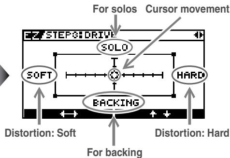
Create Tones Intuitively with EZ TONE
The EZ TONE provides an innovative user interface that enables you to create your own tones with absolutely no special knowledge of effect parameters needed.
Sound making on the EZ TONE is truly intuitive. EZ TONE shows you the way to create the sound with both graphical icons and intuitive terms such as "SOFT" or "HARD." Choose the basic sound you want according to the music genre, song imagery, performance-style. Then you can shape the sound by just moving the cursor on the TONE GRID toward "SOFT" or "HARD," "for SOLO" or "for BACKING."
Now everyone can easily create his or her own tones the instant a sonic image comes to mind.
Phrase Loop Feature
The Phrase Loop feature lets you record and play loop performances, whereby you continue adding new sounds as the loop plays.
Up to 38 seconds of recording time means you can switch effects as you add rhythm, solos, and other performance touches to a recorded loop.
You can also take phrases recorded beforehand without effects and then apply the perfect tone, adding the effects as you play back the phrase.
A Wide Variety of Tones with Parallel Chain
The GT-10 features a "Parallel Chain" function, which allows you to split the effects "chain"—the sequence of effects used in processing the sound—to create two independent chains. Each chain gives you full freedom to arrange effects in any order you want.
You can, for example, use separate chain settings in the left and right stereo channels to produce an effect just like a twin guitar sound. Additionally, using a dynamic-type COSM amp, you can even switch chains with your picking dynamics.
Works Like a Compact Effects Processor
Operating the GT-10 is like using compact effects processors. It's easy to make super-fast tone adjustments, even in the middle of live performances. Just select an effect type, then directly adjust the four optimal parameters with the front-panel knobs. Of course, you can also switch the display to show all effect parameters to create tones with even more exacting detail.
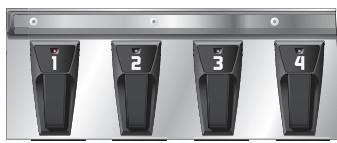
High-Visibility Indicators
Foot pedal indicators and other lights all utilize brightly lit LEDs. Clearly visible in any situation, whether it be in a live outdoor concert or up on a pitch-black stage, these indicators help ensure accurate operation.
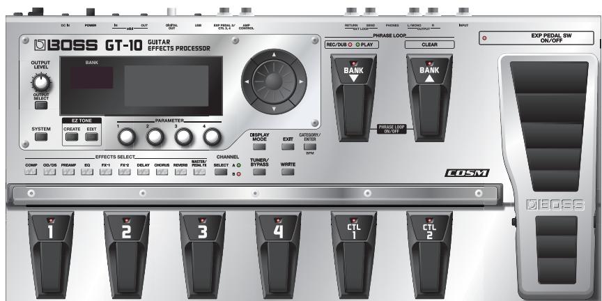
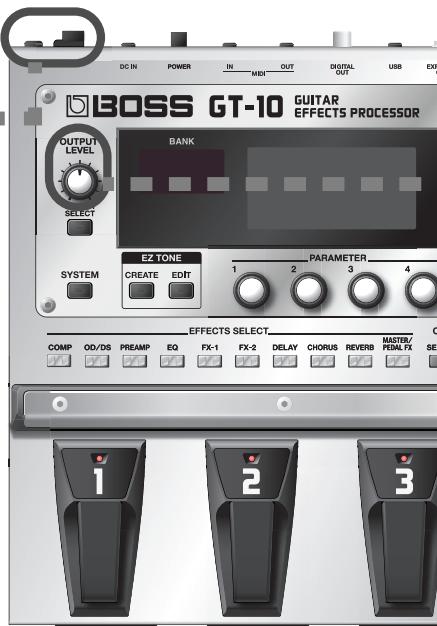
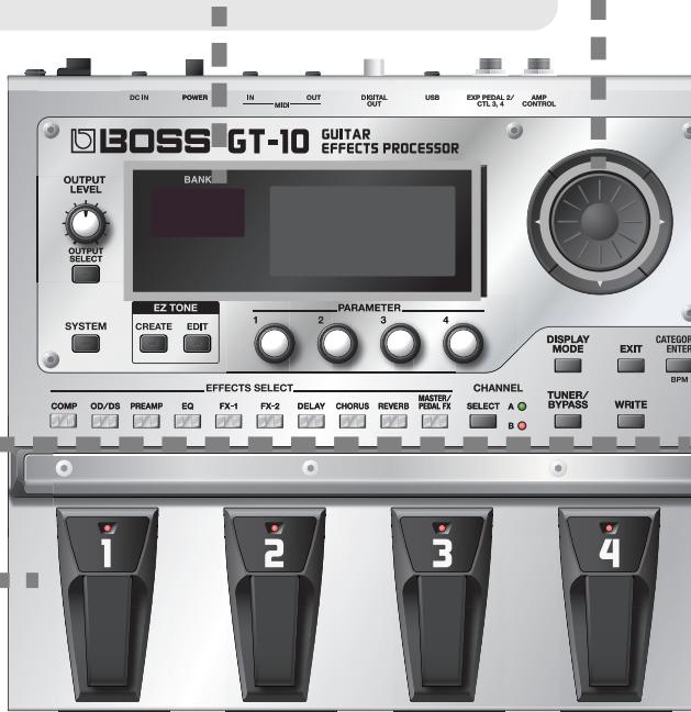
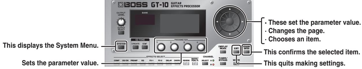
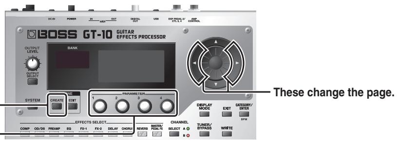
Front Panel
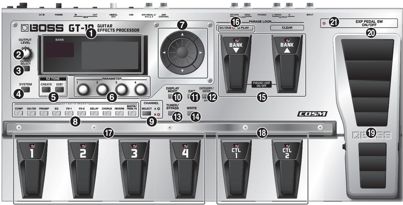
1. Display
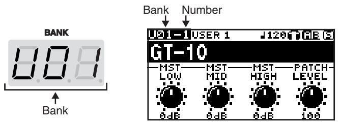
Various information about the GT-10 is shown here. The display screen on the left side shows the bank number.
2. OUTPUT LEVEL Knob
This adjusts the volume level at the OUTPUT jack and the PHONES jack.
3. OUTPUT SELECT Button
This adjusts the characteristics of the output from the GT-10 to match the type of equipment that is connected (p. 24).
4. SYSTEM Button
This makes global settings for the GT-10 (p. 61).
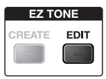
5. EZ TONE
CREATE Button
This makes it easy to create tones based on the musical genre and the feel of the song you have in mind (p. 32).
EDIT Button
This provides a simple way to modify tones (p. 33).
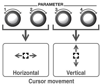
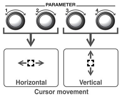
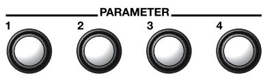
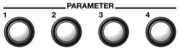
6. Parameter Knobs P1 Through P4
These change the values of the parameter shown on the display.
7. Dial
This switches patches and modifies values.
[ ], [ ], [ ], and [ ] (Cursor Buttons)
These move the onscreen cursor up, down, or to the left or right.
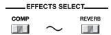
8. EFFECTS SELECT
Use these buttons to switch effects on or off, or to change their settings (p. 34). When an effect is switched on, the button's indicator lights up; the indicator goes out when the effect is off.
- [MASTER/PEDAL FX] does not light up.
COMP (Compressor) Button
OD/DS (Overdrive/Distortion) Button
PREAMP Button
EQ (Equalizer) Button
FX-1 Button
FX-2 Button
DELAY Button
CHORUS Button
REVERB Button
MASTER/PEDAL FX (Master/Pedal Effect) Button
9. SELECT Button
These switch between the A and B channels for the PREAMP (p. 98).
10. DISPLAY MODE Button
Allows you to change the way things are shown in the display (p. 24).
11进出口
Use this to go back to the previous screen or to cancel an operation.
12. CATEGORY/ENTER Button
Use this button for the following operations:
- When executing an operation
- When selecting patches arranged by category (p. 31)
- When doing tap input for MASTER BPM (p. 122) or Delay Time (p. 119)
13. TUNER/BYPASS Button
Press to use the tuner features (p. 26).
14. WRITE Button
Use this to store patch settings in memory, or to replace or copy settings (p. 42).
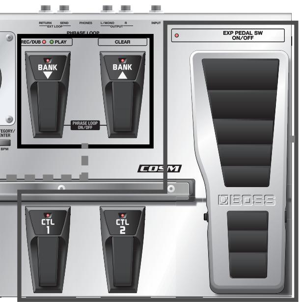
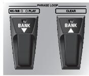
15. BANK Pedals
Use these when switching patch banks (p. 30) or performing operations with phrase loops (p. 58).
MEMO
You can switch a phrase loop on or off by depressing the two BANK pedals at the same time (p. 58).
16.PHRASE LOOP (p. 58)
REC/DUB (Recording/Over dubbing) Indicator
This lights steadily when you're recording or overdubbing a phrase, and flashes during recording standby.
PLAY Indicator
This lights up while phrase playback is in progress.
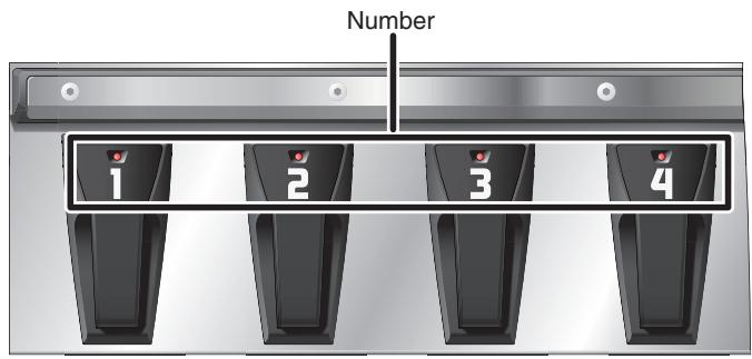
17.Number Pedals 1 through 4
These switch the patch number (p. 30).
18. CTL (Control) Pedals 1 and 2
These can be used to control a variety of functions you assign, such as the A and B channels for the PREAMP (p. 98) or switching the Tuner on or off (p. 47).
19. EXP (Expression) Pedal
Controls volume, wah, and other parameters (p. 47).
NOTE
When operating the EXP Pedal, be careful not to get your fingers pinched between the movable part and the panel. In places with small children, an adult should provide supervision and guidance until the child is capable of following all the rules essential for the safe operation of the unit.
20. EXP PEDAL SW (EXP Pedal Switch)
The switch is turned on or off by firmly pressing on the toe of the EXP Pedal.
21.exp PEDAL SW ON/OFF
(EXP Pedal Switch On/Off) Indicator
This lights up when the feature controlled by the EXP PEDAL SW is on and goes out when the controlled feature is off.
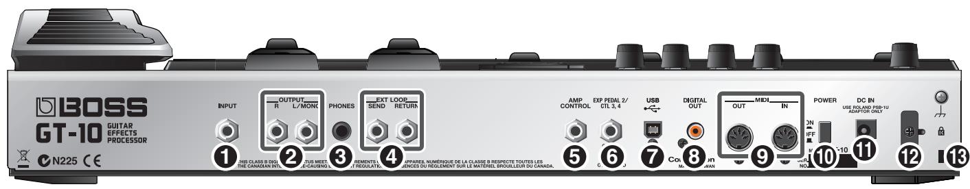
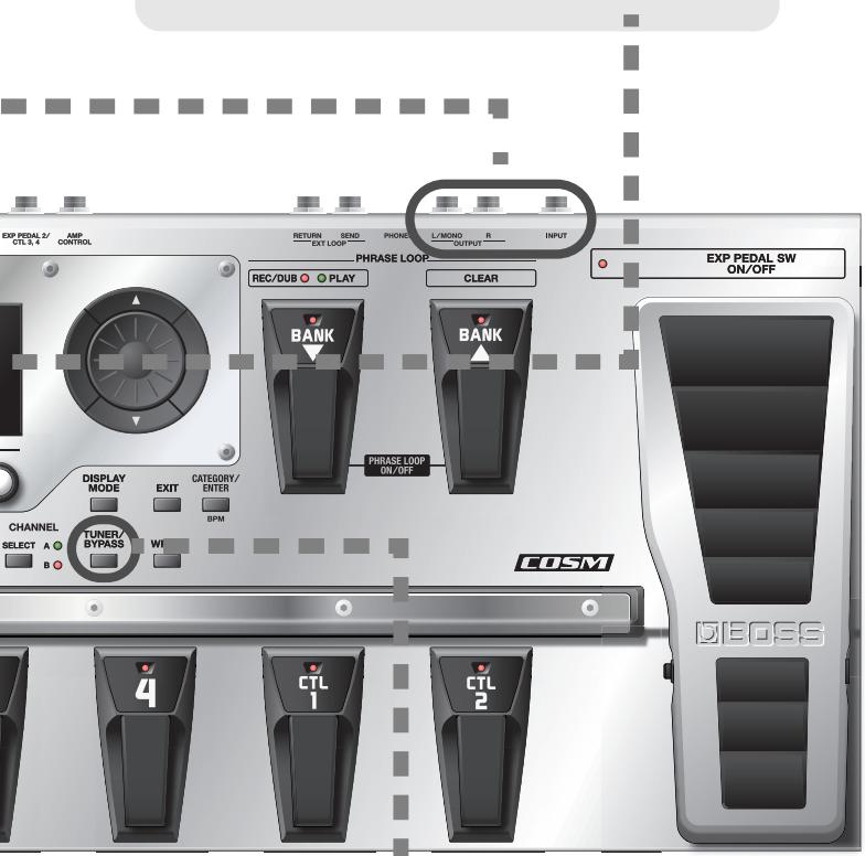
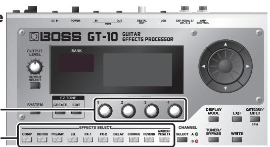
Rear Panel
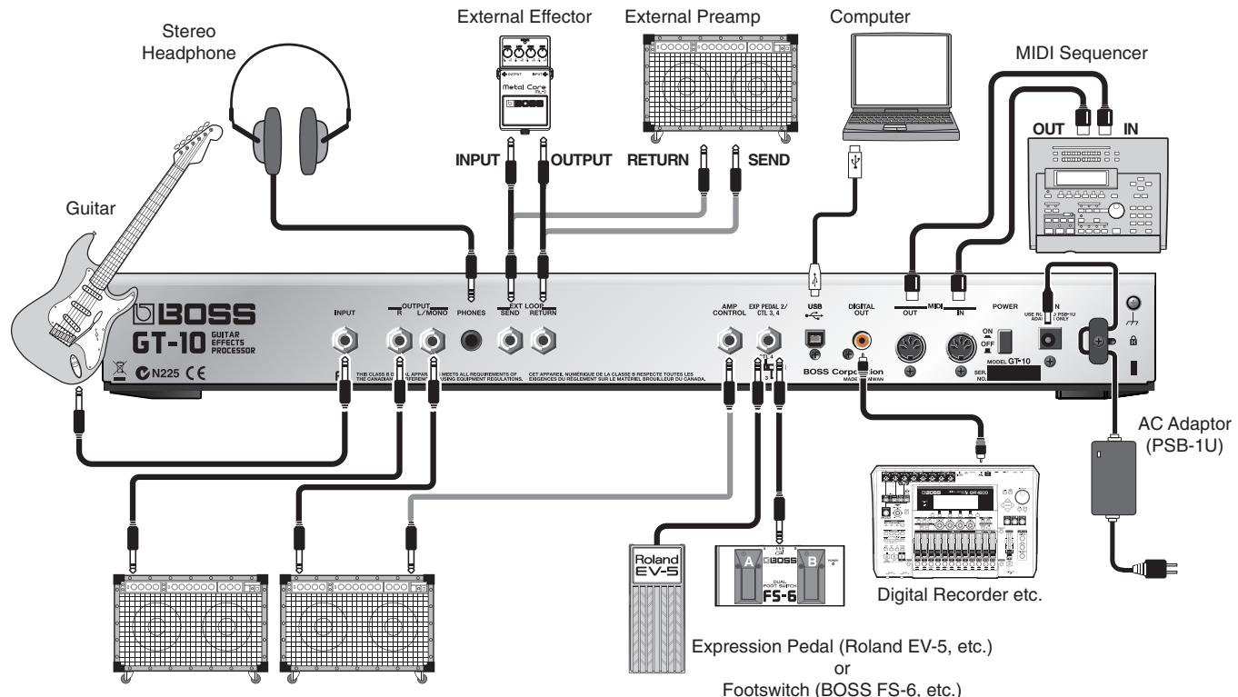
1. INPUT Jack
The guitar is connected here.
2. OUTPUT L/MONO R Jacks
Connect to your amp, mixer, or such device.
3. PHONES Jack
Connect headphones here.
MEMO
When headphones are connected to the PHONES jack, tonal adjustments are applied so the sound is close to that produced by a guitar amp.
4. EXT LOOP SEND RETURN Jacks
Connect to external effects processor or amp.
5. AMP CONTROL Jack
When using the AMP CONTROL function (p. 132), connect to the jack used for switching guitar amp channels.
6. EXP PEDAL/CTL 3, 4 Jack
Connect an optional expression pedal (such as the Roland EV-5) or footswitch (such as the BOSS FS-6) here (p. 22).
7. USB Connector
Use a USB cable to connect a computer to this connector and enable exchange of data between the GT-10 and the computer (p. 90).
8. DIGITAL OUT Connector
Outputs digital audio signals (p. 66).
9. MIDI IN/OUT Connectors
Connect an external MIDI device to these connectors to transmit and receive MIDI messages (p. 79).
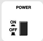
10. POWER Switch
Turns the power on and off.
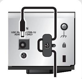
11.DC IN (AC Adaptor) Jack
Connect the included AC adaptor here.
- To prevent damaging the GT-10, please be sure not to use any AC adaptor other than the one included with the GT-10.
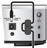
12. Cord Hook
Hook the AC adaptor cord here to prevent the adaptor plug from being disconnected (p. 22).
- Disconnecting the AC adaptor while the GT-10 is in use may result in corruption of important data.
13. Security Slot (K)
Connect a commercially available anti-theft security cable here.
http://www.kensington.com/
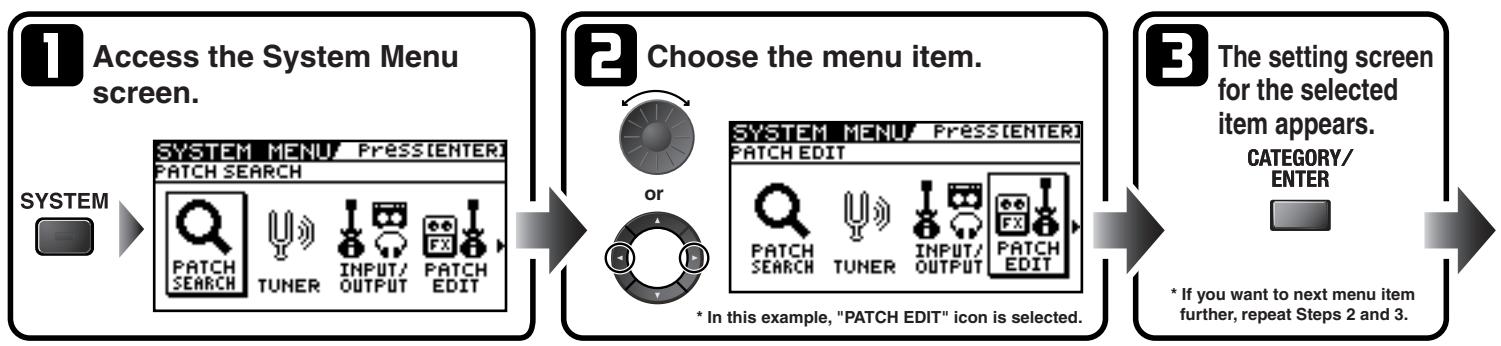
The Quick Guide describes required settings and basic operations. For detailed descriptions of operations, refer to the explanations in chapter 1 and after.
Getting Ready
1 Connect the Guitar and Amp
1. Connect the guitar and the guitar amp.
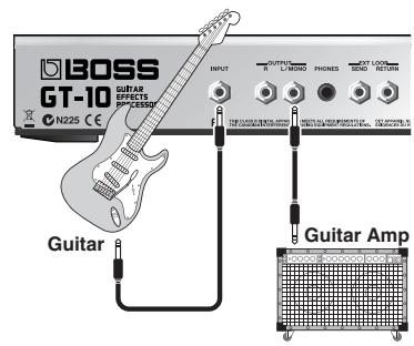
Before turning on the power, confirm the following.
- Are all external devices properly connected?
- Is the volume on the GT-10, your amp, and all other connected devices turned down to the minimum level?
NOTE
Raise the amp volume only after turning on the power to all connected devices.

For detailed information on how to make the connections, refer to "Making the Connections" (p. 22).

Turn On the Power
NOTE
Once the connections have been completed, turn on power to your various devices in the order specified. By turning on devices in the wrong order, you risk causing malfunction and/or damage to speakers and other devices.
- Insert the DC plug on the AC adaptor into the DC IN jack on the GT-10.
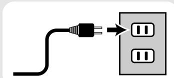
- Plug the AC adaptor into a power outlet.
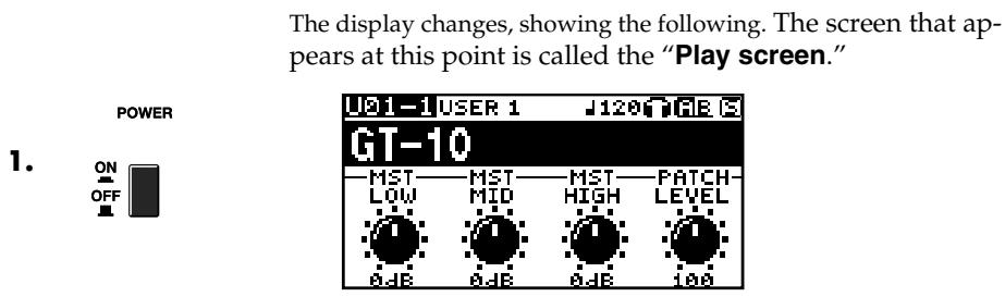
- Use the POWER switch to switch on the power.
- Power up the guitar amp.

For information on how to switch off the power, refer to "Turning Off the Power" (p. 25).

Use the OUTPUT LEVEL knob to adjust the volume level.
Tune the Guitar
Each press of the TUNER/BYPASS button switches the Tuner feature on or off.
Switching on the Tuner feature enables direct output of input sounds (bypass), and lets you tune the guitar while in this state. For more information, refer to "Tuning the Guitar (TUNER)" (p. 26).
Examples of Connections Using the SEND/RETURN Jacks
Example 1: Using an External Effects Unit
This enables use as one of the GT-10's effects.
Example 2: Using Send and Return on the Guitar Amp
This allows you to switch between use of the GT-10 and the guitar amp's preamp.
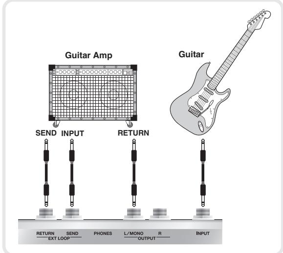
- When you're making connections using the SEND/RETURN jacks, you also need to make settings for the "SEND/RETURN" (p. 132).
Playing Sounds
Once you've finished getting ready to play, try playing sounds as you operate the GT-10.
Choosing a Patch in the Current Bank
Choose the patch you want to use by depressing the corresponding number pedal.
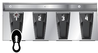
The indicator for the number pedal you pressed lights up and the patch is switched.
Choosing a Patch in a Different Bank
- Press the BANK pedals to select the desired bank.
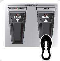
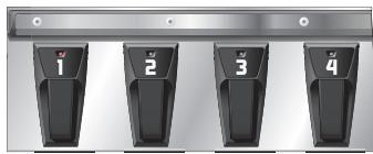
The GT-10 stands by for specification of the patch number, and the number pedal indicators blink.
- Choose the patch you want to use by depressing the corresponding number pedal.
The indicator for the number pedal you pressed lights up and the patch is switched.
NOTE
If you're not at the Play screen (p. 23), you won't be able to switch patches. Press the [EXIT] button to go back to the Play screen, then choose the patch.
MEMO
You can also use the BANK pedals to operate the Phrase Loop feature. Phrase Loop is a feature that lets you record a performance and play it back as a loop. For more information, refer to "Phrase Loop Play" (p. 58).
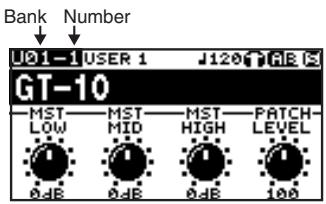
About the Bank and Number Display
The display on the left side shows the bank, and the display on the right side shows the bank and patch number.
What is a Patch?
A combination (or set) of effects together with a group of parameter settings is called a "patch." The GT-10 can store 400 different patches in memory, organized by bank and number as shown below.
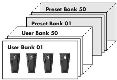
Patches include User patches, which you can use to save the settings for newly created effects, and Preset patches, for which modified settings cannot be saved. For more information, refer to "Selecting a Tone (Patch Change)" (p. 29).
Switch the Patch with the Dial
When you're at the Play screen (p. 23), turning the dial switches the patch.

Working with Effects Using the Pedals
The EXP Pedal and the CTL 1 and 2 pedals can be set to use in switching effects on or off for individual patches, use as a volume pedal, and other such operations.
Executing these operations during a performance lets you modify the sound more effectively.
| Press the CTL 1 pedal. The CTL1 pedal function is switched on. (The indicator for the CTL 1 pedal lights up.) Press a second time to switch off. (The indicator for the CTL 1 pedal goes out.) | |
| Press the CTL 2 pedal. The CTL2 pedal function is switched on. (The indicator for the CTL 2 pedal lights up.) Press a second time to switch off. (The indicator for the CTL 2 pedal goes out.) | |
| Press the toe of the EXP Pedal. The EXP Pedal value rises. | |
| Press the heel of the EXP Pedal. The EXP Pedal value decreases. | |
| Press the toe of the EXP Pedal firmly. The EXP PEDAL SW function is switched on. (The EXP PEDAL SW ON/OFF indicator lights up.) Press firmly a second time to switch off. (The EXP PEDAL SW ON/OFF indicator goes out.) |

You can assign the parameters you want to the EXP Pedal, EXP PEDAL SW and the CTL 1 and 2 pedals and operate them accordingly. For more information, refer to "Using Pedals to Control the Parameters" (p. 47)."
Editing
Basic Operation
This describes the basic operations you use when editing settings.

Buttons and Knobs You Use
Creating Sounds Based on Existing Patches
Let's try creating a new sound based on a patch whose sound is close to what you want to make.
Switching Effects On and Off
-
Choose a patch whose sound is close to the sound you want to create (p. 16).
-
Choose the effect you want to switch on or off.

For more information about each parameter, refer to "Chapter 8 Parameters Guide" (p. 96).
- Again press the button you pressed in step 2. The effect is switched on or off. Effect on: button illuminated Effect off: button extinguished

Buttons and Knobs You Use
These set the parameter value. These choose the effect.
Adjusting Effect Parameters
-
Switch on the effect you want to adjust.
-
Adjust the parameters for the effect.

For more information about each parameter, refer to "Chapter 8 Parameters Guide" (p. 96).
- Repeat steps 1 and 2 until you obtain the sound you want.
NOTE
If you switch patches, all settings that have been made will be lost. To save the sound you've created, carry out the Write procedure (p. 42).
Creating Sounds with Ease
Using the EZ Tone feature (p. 32) lets you quickly find settings close to the musical genre and feel of the song you want to create, and enables you to create the sound easily. Let's try creating sounds using EZ Tone.
TIP
Buttons and Knobs You Use
This starts the EZ Tone feature.
These set the parameter values.
3 Adjust the Distortion
Using Tone Grid, adjust the distortion until you get the sound you want.

4 Adjust the Other Effects
Using Tone Grid, adjust the effects until you get the sound you want.
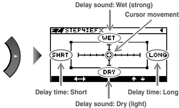
Ex. When you adjust the Delay
NOTE
If you switch patches, you'll lose all the settings you've made. To save the sound you've created, carry out the Write procedure (p. 42).
TIP
You can take parameters you've adjusted with EZ TONE CREATE and fine-tune them further using EZ TONE EDIT or parameter operations. For more information, refer to "Adjusting the Tone (Edit)" (p. 33).
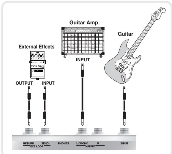
Making the Connections
Guitar Amplifier
NOTE
- To prevent malfunction and/or damage to speakers or other devices, always turn down the volume, and turn off the power on all devices before making any connections.
- Raise the amp volume only after turning on the power to all connected devices.
- When connection cables with resistors are used, the volume level of equipment connected to the INPUT jack may be low. If this happens, use connection cables that do not contain resistors.
- When outputting in mono, connect the cable to the OUTPUT L/MONO jack.
- Use only the specified expression pedal (Roland EV-5 or BOSS FV-500L; sold separately). By connecting any other expression pedals, you risk causing malfunction and/or damage to the unit.
- Depending on the circumstances of a particular setup, you may experience a discomforting sensation, or perceive that the surface feels brittle to the touch when you touch this device, microphones connected to it, or the metal portions of other objects, such as guitars. This is due to an infinitesimal electrical charge, which is absolutely harmless. However, if you are concerned about this, connect the ground terminal (see figure) with an external ground. When the unit is grounded, a slight hum may occur, depending on the particulars of your installation. If you are unsure of the connection method, contact the nearest Roland Service Center, or an authorized Roland distributor, as listed on the "Information" page.
Unsuitable places for connection
Water pipes (may result in shock or electrocution)
Gas pipes (may result in fire or explosion)
- Telephone-line ground or lightning rod
(may be dangerous in the event of lightning)
- Place the AC adaptor so the side with the indicator (see illustration) faces upwards and the side with textual information faces downwards.
The indicator will light when you plug the AC adaptor into an AC outlet.
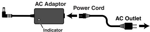
MEMO
- To prevent the inadvertent disruption of power to your unit (should the plug be pulled out accidentally), and to avoid applying undue stress to the AC adaptor jack, anchor the power cord using the cord hook, as shown in the illustration.
- When connecting an expression pedal to the EXP PEDAL2/CTL 3,4 jack, set the minimum volume for the connected expression pedal to the "MIN" position.
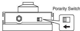
- When connecting a BOSS FS-6 footswitch (optional) to the EXP PEDAL 2/CTL 3,4 jack, set the MODE switch and POLARITY switch as shown below.
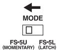

- When connecting a BOSS FS-5U footswitch (optional) to the EXP PEDAL 2/CTL 3,4 jack, set the POLARITY switch as shown below.
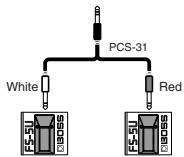
- You can use the special (optional Roland) PCS-31 connector cord to connect two footswitches.
cf.
- When using the unit with an expression pedal or a footswitch (the optional FS-6 or FS-5U) connected to the EXP PEDAL 2/CTL 3,4 jack, make the settings given on "Using Pedals to Control the Parameters" (p. 47).
- For more on using the AMP CONTROL jack, refer to "AMP CONTROL" (p. 132).
Turning on the Power
Before turning on the power, confirm the following.
- Are all external devices properly connected?
- Is the volume on the GT-10, your amp, and all other connected devices turned down to the minimum level?
NOTE
Once the connections have been completed, turn on power to your various devices in the order specified. By turning on devices in the wrong order, you risk causing malfunction and/or damage to speakers and other devices.
MEMO
- Upon power-up, the patch most recently selected when the power was last turned off is selected.
- This unit is equipped with a protection circuit. A brief interval (a few seconds) after power up is required before the unit will operate normally.
-
The explanations in this manual include illustrations that depict what should typically be shown by the display. Note, however, that your unit may incorporate a newer, enhanced version of the system (e.g., includes newer sounds), so what you actually see in the display may not always match what appears in the manual.
-
Turn on the power to any external effects processors the guitar amp (power amp).
The Icons in the Play Screen
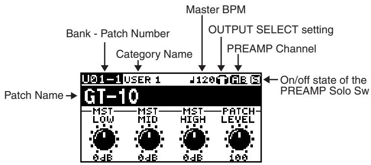
| 1120 Displays the Master BPM (p. 122) value for each patch. | ||
| 6E | When the PREAMP Ch.Mode is set to Single, preamp channel A is se- lected. | When the PREAMP Ch.Mode is set to Dynamic, the display switches be- tween A and B according to the input level. |
| 4B | When the PREAMP Ch.Mode is set to Single, preamp channel B is select- ed. | |
| 13 | This is displayed when the PREAMP Ch.Mode is set to Dual Mono or Dual L/R. | |
| 3 | This is displayed when the PREAMP Solo Sw is Off. | |
| 8 | This is displayed when the PREAMP Solo Sw is On. | |
cf.
For details on the OUTPUT SELECT icons, refer to "Making Settings for a Connected Device (Output Select)" (p. 24).
Switching the Play Screen
The GT-10 has a variety of Play screen variations. You can switch the information shown in the Play screen by pressing

MEMO
- You can use the PARAMETER knobs 1 through 4 to work with the values of the parameters displayed at the bottom of the Play screen. Also, for each parameter, you can change the corresponding assignment at the SYS KNOB ASSIGN screen (p. 46).
The parameter name displayed at the each Play screen is abbreviated. For details about parameter names, refer to "Parameters You Can Set with PDL:CTL/EXP" (p. 125) or "Display of Parameters You Can Set with SYS KNOB SETTING" (p. 138).
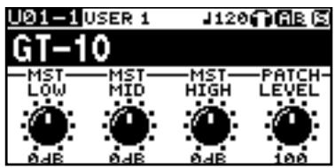
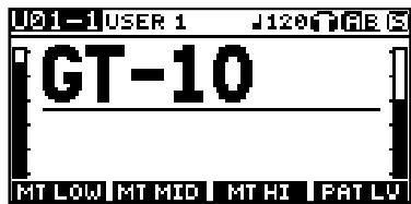
Screen 1
This displays the name of the patch and the parameters you can work with using the PARAMETER 1 through 4 controls.
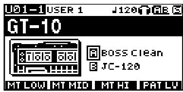
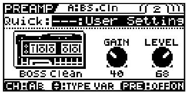
Screen 2
The patch name is displayed, along with the patch's preamp selections and an icon for the preamp channel that's currently in use.
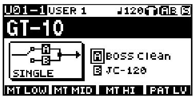
Screen 3
This screen displays the preamp channel mode and the preamp that's in use.
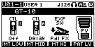
Screen 4
This screen displays the functions assigned to CTL 1 and 2, the EXP PEDAL SW, and the EXP Pedal.
* About the S icon and A icon displayed at the Screen 4 and 5.
The Sicon displays when the Pedal Function is enabled (p. 47).
The A icon displays when the Patch Assign Function is enabled (p. 50).
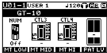
Screen 5
This screen displays the functions assigned to the Number Pedal Switch, CTL 3 and 4, the external expression pedal (EXP PEDAL2).
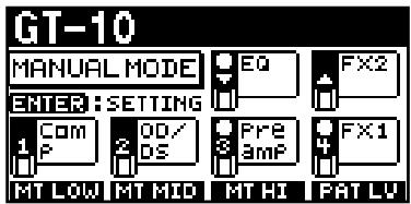
Screen 6
This is the screen shown when you're in Manual mode (p. 55). Manual mode is enabled only while this screen is displayed. Pressing [CATEGORY/ENTER] in this screen allows you to make settings for MANUAL MODE SETTING.
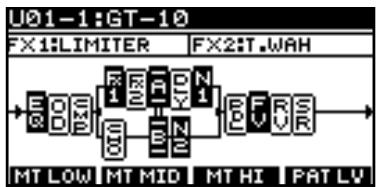
Screen 7
The effects used, as well as their connection sequence (CHAIN) in a channel is indicated.
Screen 8
The patch name and the output level meter are displayed.
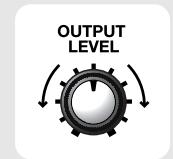
Adjusting the Output Level
1.

OUTPUT LEVEL
Adjust the GT-10's output level with the OUTPUT LEVEL knob.
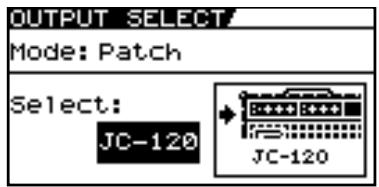
Making Settings for a Connected Device (Output Select)
Select the type of device connected to the OUTPUT jack.
MEMO
To derive the maximum performance from the GT-10, be sure to make the correct setting for OUTPUT SELECT, the one that's most suitable for your setup.
- The speaker simulator (p. 99) is enabled only when OUTPUT SELECT is set to LINE/PHONES.
- You cannot change the tone with Output Select when PREAMP On/Off (p. 98) is set to Off.
The OUTPUT SELECT settings screen appears.
1.

2.
Move the cursor to Mode.

Set the Mode.
3.
| Value | Explanation |
| Patch | This uses the patch's Output Select setting. You can use a different output setting for each individual patch. |
| System | This uses the system's Output Select setting. The same output setting is used for all patches. |
4.

Move the cursor to Select.
5.

Choose the operation for the Select parameter.
| Value | Explanation | Icon displayed on the Play screen |
| JC-120 | Use this setting when connecting to Roland's JC-120 guitar amp. | |
| SMALL AMP | Use this setting when connecting to small guitar amp. | |
| COMBO AMP | Use this setting when connecting to the guitar input of a combo amp other than the JC-120 guitar amp (where the amp and speaker or speakers are combined in a single unit).* Depending on your guitar amp, you may be able to obtain good results with the “JC-120” setting. | |
| STACK AMP | Use this setting when connecting to the guitar input of a stack-type guitar amp (where the amp and speaker or speakers are separated). | |
| JC-120 Return | Use this setting when connecting to the RETURN jack of a JC-120. | |
| COMBO Return | Use this setting when connecting to the RETURN jack with a combo amp. | |
| STACK Return | Use this setting when connecting to the RETURN jack of a stack amp or rack mounted power amp. | |
| LINE/PHONES | Use this setting when using headphones or when connecting to a multi-track recorder for recording.* When using the speaker simulator, set this to LINE/PHONES. |
Turning Off the Power
Before turning off the power, confirm the following.
-
Is the volume on the GT-10, your amp, and all other connected devices turned down to the minimum level?
-
Turn off the power to the guitar amp (power amp) any external effects processors and other devices.

- ON OFF
Tuning the Guitar (TUNER)
When the Tuner is turned on, sounds input to the GT-10 are output directly as is (bypassed), and the tuner is activated.
Under these conditions you can then tune your guitar.
Turning the Tuner Function On and Off
1.
TUNER/
BYPASS

The tuner is switched on or off.
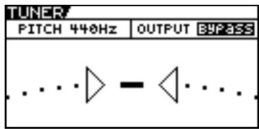
About the Display During Tuning
With the GT-10's internal tuner, the Note Name and the Tuning Guide are shown of the display, indicating the difference between the input sound and the sound in the display.
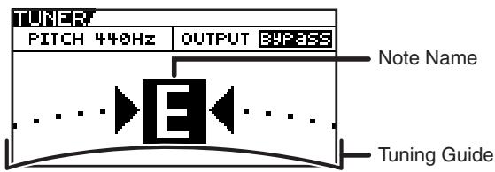
When the difference from the correct pitch falls within 50 cents, the Tuning Guide then indicates the size of that difference. As you watch the Tuning Guide, tuning until the center indicator lights up.
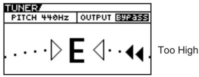
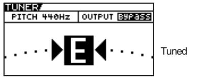
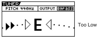
How to Tune
- Play a single open note on the string being tuned.
The Note Name closest to the pitch of the string that was played appears in the display.
- Tune the string until the string name appears in the display.
- Keep checking the Tuning Guide, tuning until the center indicator lights up.
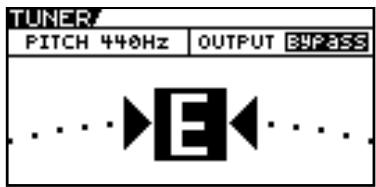
- Repeat Steps 1-3 until all of the strings are tuned.
MEMO
Only play a single note on the one string being tuned.
TIP
General Tuning
| 7th | 6th | 5th | 4th | 3rd | 2nd | 1st | |
| Regular | B | E | A | D | G | B | E |
| 1/2 Step Down | A# | D# | G# | C# | F# | A# | D# |
TIP
When tuning guitars equipped with a tremolo bar, when one string is tuned, the others may end up being out of tune. In this case, tune to the pitch indicated by the initial note name, then tune the other strings again, repeatedly fine-tuning each string.
Changing the Tuner Settings (Tuner Pitch)
1.
TUNER/
BYPASS

Turn on the Tuner.
2.
Move the cursor to PITCH.
3.

Change the reference pitch.
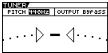
MEMO
- The frequency of A4 (the middle A on a piano keyboard) played by an instrument (such as a piano) that provides the pitch to which the other instruments refer in tuning before a performance begins is called the reference pitch.
This is set to 440Hz when shipped from the factory.
| Range | Explanation |
| 435Hz–445Hz | This sets the reference pitch. |
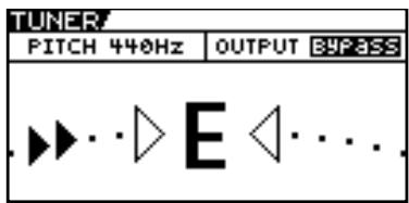
Changing the Tuner Settings (Tuner Out)
1.
TUNER/ BYPASS
BTPASS

Turn on the Tuner.
2.
Move the cursor to OUTPUT.
3.

Select the output while Tuner is on.
MEMO
- When OUTPUT is set to "Bypass," and Tuner is set to ON, you can adjust the volume of the direct sound by operating the EXP Pedal.
- OUTPUT is set to "Bypass" when shipped from the factory.
| Value | Explanation |
| Bypass | Sounds input to the GT-10 bypass the processing and are output directly as is. |
| Mute | Sounds are muted, and no sound is output. |
TIP
Switching the Tuner On and Off with the CTL Pedal
By setting the CTL Pedal function (p. 47) to "Tuner," you can switch the tuner on and off with one of the CTL pedals.
Switching the Tuner On and Off by Lifting Up on the EXP Pedal
When the EXP Pedal is functioning as a Foot Volume control, set one of the ASSIGN 1-8 Assign Variable settings (p. 50) as follows.
With these setting, you can switch on the Tuner by drawing back the EXP Pedal.
| Target: | Tuner Sw | Src Mode: | Moment |
| Min: | On | ActRngLo: | 0 |
| Max: | Off | ActRngHi: | 1-127 |
| Source: | EXP1 PEDAL |
Switching the Tuner On and Off with the Number Pedal
Set the Num Pdl Sw function (p. 57) to Tuner to switch the tuner on and off with the number pedal of the current patch.
Selecting a Tone (Patch Change)
What is a Patch?
A combination (or set) of effects together with a group of parameter settings is called a "patch."
The GT-10 can store 400 different patches in memory, organized by bank and number as shown below.
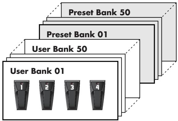
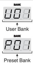
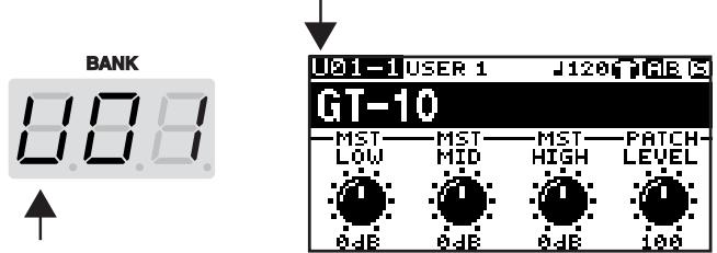
User Banks (U01-U50)
Newly created effects settings are saved in the User banks. Patches in these banks are called "User patches."
A "U" appears in the display when a User patch is selected.
Preset Banks (P01-P50)
The Preset banks contain effect settings that make full use of the features the GT-10 has to offer. The patches in these banks are called "Preset patches." When you change the settings of a Preset patch, save the result as a User patch. Preset patches cannot be overwritten.
A "P" appears in the display when a Preset patch is selected.
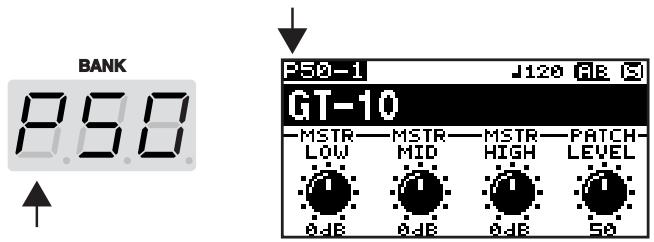
Using the Pedal to Select the Patch
Patches are switched by selecting a "bank" (U01-U50, P01-P50) and "number" (1-4). The bank and number appear in the GT-10's display as shown in the following figure.
MEMO
- When selecting a patch, even if a new bank is selected, the patch is not switched until you also choose the number. If you want to be able to switch patches merely by selecting a different bank, adjust the Bank Change mode (p. 72) setting.
- You can also set the unit so certain effects continue to be used with a following patch after you switch patches. For details, refer to "Keeping Effect Sounds Playing After Patches Are Switched (Patch Change Mode)" (p. 68).
Choosing a Patch in the Same Bank
1.
Choose the number of the patch you want to use.
Choosing a Patch in a Different Bank
1.
Select the bank.
2.
Choose the number of the patch you want to use.
MEMO
- The indicator for the selected number pedal lights up.
- On the GT-10, you cannot switch patches in any screen other than the Play screen. Press [EXIT] to return to the Play screen (p. 24).
MEMO
Press the BANK pedals to select the desired bank. After bank selection, the GT-10 stands by for specification of the patch number, and the number pedal indicators light up.
MEMO
- The indicator for the selected number pedal lights up.
- On the GT-10, you cannot switch patches in any screen other than the Play screen. Press [EXIT] to return to the Play screen (p. 24).
Using the Dial to Select the Patch
1.

Select the Patch.
MEMO
On the GT-10, you cannot switch patches in any screen other than the Play screen. Press [EXIT] to return to the Play screen (p. 24).
Separating Patches into Groups (CATEGORY)
The GT-10 includes a function that allows you to categorize patches into a number of different groups. This is called the CATEGORY function (p. 39). Specifying the category for each patch makes searching for patches more convenient.
| 1. CATEGORY/ ENTER | The CATG screen appears. The categories and the patches in these categories are shown in list format. | MEMO • On the GT-10, you cannot switch patches in any screen other than the Play screen. Press [EXIT] to return to the Play screen (p. 24). • You can also display the CATG screen from PATCH SEARCH in the SYSTEM screen. |
| CATG USER 1 J01-1 GT-10 J01-2 DUELIN 04 CRUNCH J01-3 SEATTLLE 68 J01-4 AUSTIN 86 J02-1 FAT CLEAN J02-2 BLUE S LEAD J02-3 80s LOUD MS+OD-1 | ||
| 2. | Select the category. | |
| 3. | The GT-10 switches to the selected patch. |
Adjusting a Tone
On the GT-10, the master equalizer parameters are assigned to the PARAMETER knobs of the Play screen by default. You can use these PARAMETER knobs to adjust the sound quality globally, for all patches.
| 1. | Select the Patch. | |
| 2. | P1 knob: Adjust the low frequency range tone. P2 knob: Adjust the middle frequency range tone. P3 knob: Adjust the high frequency range tone. |
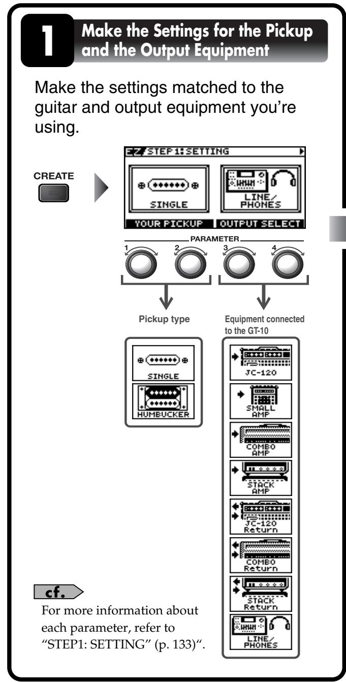
Creating Sounds with Ease (EZ TONE)
Creating a Tone for the Song You Envision (Create)
If you already have a clear idea about the kind of sound you want to create, you can save yourself a lot of trouble by starting out with a patch that is relatively similar to what you have in mind, then tweak its settings until you arrive at what you want.
EZ TONE CREATE lets you create sounds easily by choosing settings close to the musical genre and the feel of the song you want to compose.
| The SETTING screen for EZ TONE CREATE appears. | ||
| EZ/TONE CREATE EDIT | EZ/STEP1:SETTING SINGLE | LINE/ PHONES |
| YOUR PICKUP OUTPUT SELECT | ||
| P1, P2 knob: This selects the pickup type. P3, P4 knob: This selects the equipment connected to the GT-10. | ||
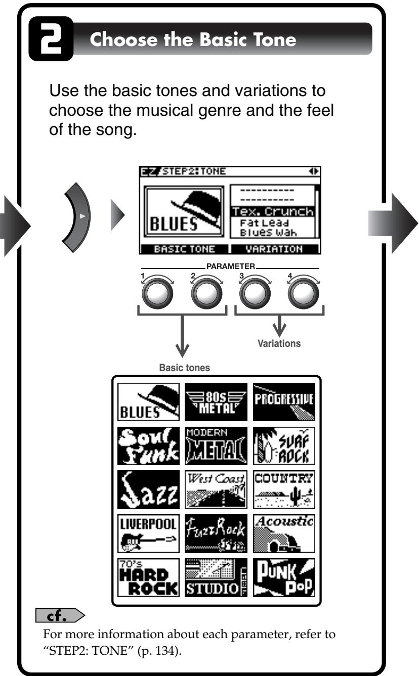
| The TONE screen for EZ TONE CREATE appears. | ||
| EZ/STEP2: TONE BLUES | TEX, Crunch Fat Lead Blues Wah | |
| BASIC TONE VARIATION | ||
| P1, P2 knob: This selects the basic tone. P3, P4 knob: This selects a variation. | ||
| The DRIVE Tone Grid for EZ TONE CREATE appears. | ||
| EZ/STEP3: DRIVE SOLO | HARD | |
| SOFT BACKING | ← | | + | ← | |
| P1, P2 knob: This adjusts the distortion (DRIVE). P3, P4 knob: This adjusts the volume level of the distortion. | ||
| The EFX Tone Grid for EZ TONE CREATE appears. | ||
| EZ/STEP4:EFX | WET SHRT | | LONG | |
| ← | | + | ← | ||
| Adjust the effects until you get the sound you want. (Ex.) When you adjust the Delay effect P1, P2 knob: Adjusts the delay time. P3, P4 knob: Adjusts the volume level of the delay. | NOTE Switching patches causes all settings that have been made to be lost. To save the sound you've created, carry out a Write operation (p. 42). MEMO You can take parameters you've adjusted with EZ TONE CREATE and fine-tune them further using EZ TONE EDIT or parameter operations. For more information, refer to “Adjusting the Tone (Edit)” (p. 33). | |
Adjusting the Tone (Edit)
By using EZ TONE EDIT you can adjust the sound of a patch with ease, without having to manipulate complicated parameters.
The EZ TONE EDIT screen appears.
1.
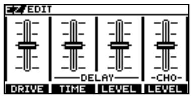
2.

P1 knob: Adjusts the distortion (DRIVE).
P2 knob: Adjusts the delay time.
P3 knob: Adjusts the volume level of the delay.
P4 knob: Adjusts the volume level of the chorus.
Setting the Effects
Turning an Effect On and Off
The GT-10's internal effects are switched on and off with button controls. When an effect is switched on, the button's indicator lights up; the indicator goes out when the effect is off.
MEMO
[MASTER/ PEDAL FX] does not light up.
The setting screen for the effects appears.
(Press the button you pressed in step 1 a second time.) 2. COMP \~ REVERB The effect is switched on or off.
- To select another effect to be switched on and off, repeat Steps 1 and 2.
MEMO
- With [FX-1] and [FX-2], the settings for the currently selected effect are shown.
- Pressing [MASTER/PEDAL FX] displays the MST/PDL FX screen.
MEMO
- If you want to name the patch or edit the name, proceed to "Naming a Patch (PATCH NAME)" (p. 41) before you save.
- If you want to save a tone with the settings you've made, proceed as described in "Saving a Patch (PATCH WRITE)" (p. 42).
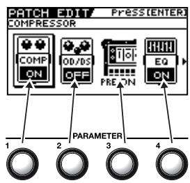
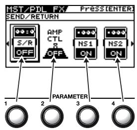
On/Off Operations Using the PARAMETER Knobs
You can use the P1 through P4 knobs to switch on or off the effects whose icons are displayed in the PATCH EDIT screen or MST/PDL FX screen.
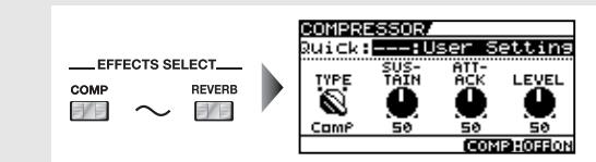
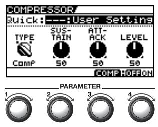
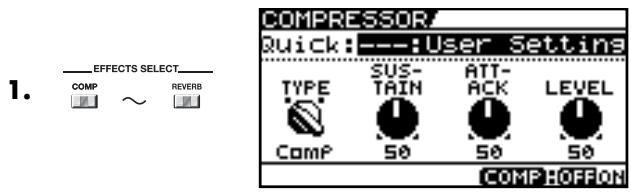
Setting the Effects Simply (Quick Setting)
Each effect includes prepared sample settings called "Quick Settings."
You can easily create new effect sounds just by selecting and combining these Quick Settings.
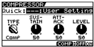
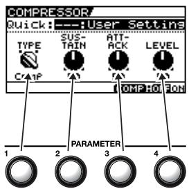
| The setting screen for the effects appears. | MEMO • With FX-1 and FX-2, the settings for the currently selected effect are shown. • Pressing [MASTER/PEDAL FX] displays the MST/PDL FX screen. • “----: User Setting” indicates that the effect indicated in the display is set to be saved to the currently selected patch, or that the settings are currently being modified. | |
| COMPRESSOR Quick:User Setting TYPE SUS-ATT-PICK LEVEL Comp 50 50 50 COMPHOFFON | ||
| Select the Quick Setting you want. U**:User Quick Setting P**:Preset Quick Setting MEMO For PREAMP, the various FX-1 or FX-2 effects, or the ASSIGN 1 through 8 Quick Settings, you can call up the respective settings described below. • PREAMP (You can call up settings separately for channel A and B.) U01-1.A - U50-4.B:User Patch Setting P01-1.A - P50-4.B: Preset Patch Setting • Each effect of the FX-1 or FX-2 (You can call up settings separately for FX1 and FX2.) U01-1.1 - U50-4.2:User Patch Setting P01-1.1 - P50-4.2: Preset Patch Setting • ASSIGN (You can call up settings separately for ASSIGN 1 through 8) U01-1.1 - U50-4.8:User Patch Setting P01-1.1 - P50-4.8: Preset Patch Setting | MEMO • When FX-1 or FX-2 has been selected in Step 1, the settings for the effect selected by means of the FX1/FX2 Select parameter (p. 102) are switched. • When PREAMP has been selected in Step 1, you can choose different of settings for channel A and B. • If you want to name the patch or edit the name, proceed to “Naming a Patch (PATCH NAME)” (p. 41) before you save. • If you want to save a tone with the settings you've made, proceed as described in “Saving a Patch (PATCH WRITE)” (p. 42). | |
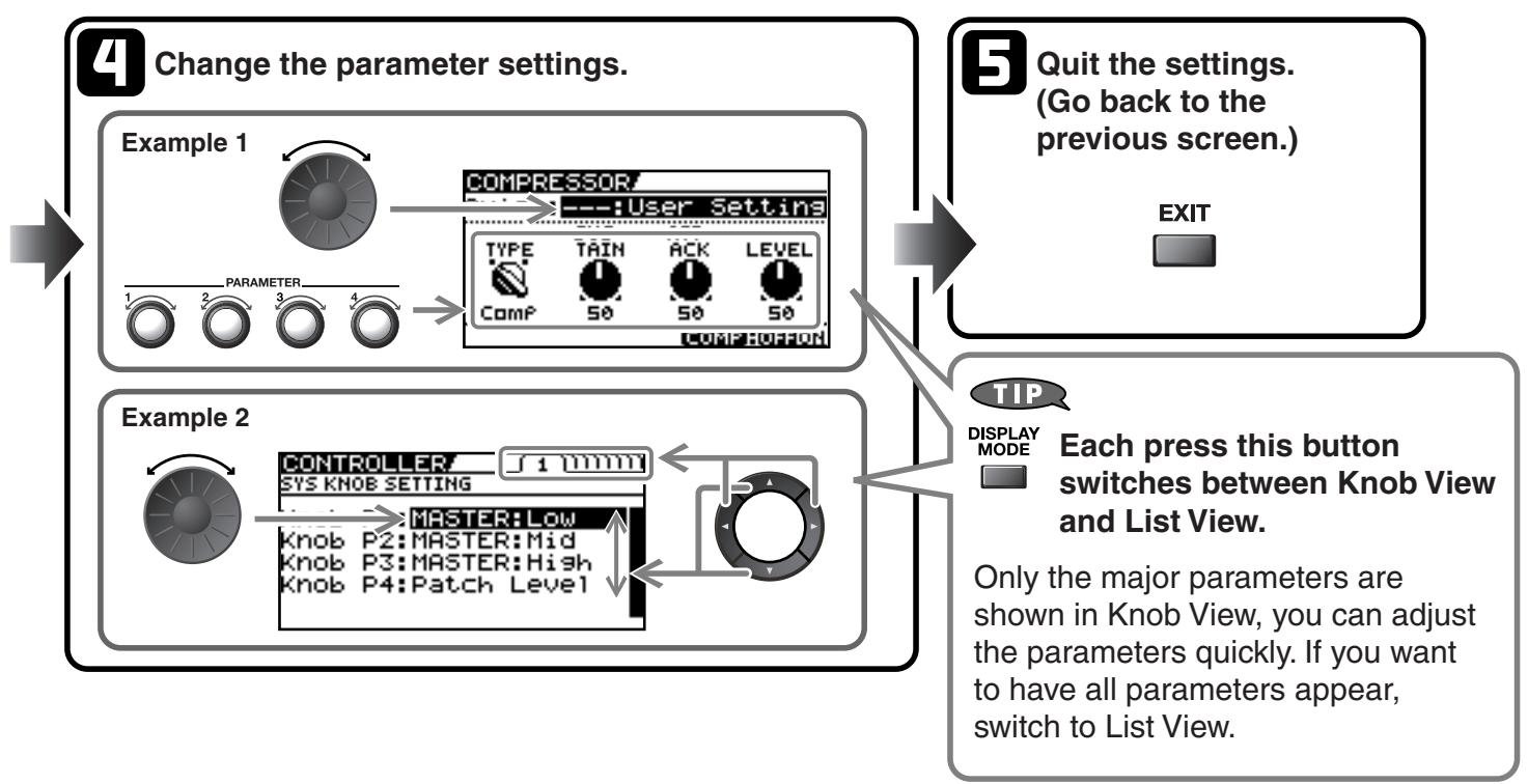
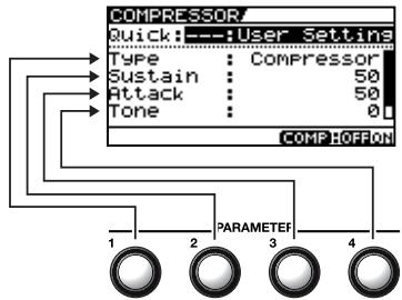
Switching Between Knob View and ListView
You can switch the setting screen for effects between a knob-format view and a list-format view.
| 1. EFFECTS SELECT COMP ~ REVERSE | The setting screen for the effects appears. | With [FX-1] and [FX-2], the settings for the currently selected effect are shown. | |
| Each press switches between Knob View and List View. Only the major parameters are shown in Knob View, you can adjust the parameters quickly. If you want to have all parameters appear, switch to List View. | |||
| DISPLAY MODE | COMPRESSOR Quick:User Settings TYPE SUS- TRAIN ATT- ACK LEVEL Comp 50 50 50 COMP OFFON | ←→ | Compressor/ Quick:User Settings TYPE Compressor Sustain 50 Attack 50 Tone 0 |
Adjusting the Parameters
Each effect comprises several different kinds of parameters. You can more precisely create the sounds you want by editing each of these parameters individually.
The setting screen for the effects appears.
1.
2.
Make the settings for the parameters.
- To adjust another effect parameter, repeat Steps 1 and 2.
MEMO
- With [FX-1] and [FX-2], the settings for the currently selected effect are shown.
- Pressing [MASTER/PEDAL FX] displays the MST/PDL FX screen.
MEMO
Some effects include multiple pages for the parameter settings. You can use [ ] and

] to switch the pages.
MEMO
- If you want to name the patch or edit the name, proceed to "Naming a Patch (PATCH NAME)" (p. 41) before you save.
- If you want to save a tone with the settings you've made, proceed as described in "Saving a Patch (PATCH WRITE)" (p. 42).
Operations Using the PARAMETER Knobs
In the effects screens, the knobs correspond to the displayed parameters.
Selecting TYPE for OD/DS or PREAMP
Changing the OD/DS or PREAMP screen to Knob View lets you make the selection for TYPE using the P1 knob and [▼] and [▲].
The TYPE values for OD/DS and PREAMP are grouped into several categories.
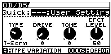
P1 knob: This selects the general category for OD/DS (or PREAMP).

These select the TYPE value within the category.

For details, refer to "Chapter 8 Parameters Guide" (p. 96).
Adjusting EQ (Equalizer)
In the EQ screen, using [DISPLAY MODE] to switch the screen lets you check the current status of the settings by means of a graph.
Use [] and [] to switch pages, and use the P1 through P4 knobs to adjust the respective parameters.

You can use the same technique to adjust the various parameters under PARA EQ for FX-1 and FX-2 as well.
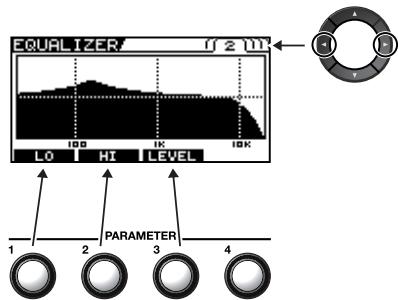

For details, refer to "Chapter 8 Parameters Guide" (p. 96).
Adjusting GRAPHIC EQ for FX-1/2
In the GRAPHIC EQ screen for FX-1 or FX-2, using [DISPLAY MODE] to switch the screen lets you check the current status of the settings by means of a slider view.
Use [] and [] to select the range you want to adjust, and use the P1 through P4 knobs to adjust the respective parameters.
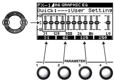

For details, refer to "Chapter 8 Parameters Guide" (p. 96).
Changing the Connection Order of Effects (Effect Chain)
Here's how you can change the order in which the effects are connected.
| 1. | The MST/PDL FX screen appears. | |
| 2. | Select FX CHAIN. | |
| 3. | The FX CHAIN screen appears. | |
| 4. | Select an effect you want to move. | |
| 5. | Pressing the effect button for the effect you want to move lets you choose the effect. | |
| 6. | Move an effect to the point where you want to have an effect inserted. |
Checking the Effect Level with the Level Meter
In the upper right of the FX CHAIN screen, you can meter the output level of each effect.
To check an effect's output level, move the cursor to the desired effect.
MEMO
You can check the level of signals being input to the INPUT jack by selecting
Selecting allows you to check the level of signals output from the GT-10.
Grouping Patches by Category (CATEGORY)
You can assign categories to patches and group them accordingly.
| 1. | Select the patch you want to include in a category. | |
| 2. | The MST/PDL FX screen appears. MST/PDL FX PRESSENTER MASTER BPM KEY ASSIGN | |
| 3. | Select NAME. MST/PDL FX PRESSENTER PATCH NAME ABC FOX CHAIN NAME | |
| 4. | The PATCH NAME screen appears. | |
| 5. | Select a category. PATCH CATEGORY USER 1 GT-1# | |
| ABCDEFHJKLMNOPRSTUWXYZ DECURSOR INS DEL CATG | If you want to name the patch or edit the name, proceed to "Naming a Patch ( patches)" (p. 41) before you save. If you want to save a name of the patch with the settings you've made, proceed to "Saving a Patch (Patches)" (p. 42). |
Naming User Categories (CATEGORY NAME)
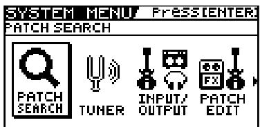
The CATEGORY function also features ten user categories (USER1-10) you can name however you like.
| The SYSTEM MENU screen appears. | ||
| SYSTEM MENU Press ENTER PATCH SEARCH Q PATCH SEARCH TUNER INPUT/ OUTPUT PATCH EDIT | ||
| 1. SYSTEM Choose category name. Select CATEGORY NAME. SYSTEM MENU PressEnter USER CATEGORY NAME LCD MIDI USB ABC CATEGORM NAME | ||
| 2. | The CATEGORY NAME screen appears. | |
| 3. CATEGORY/ ENTER | CATEGORY NAME USER CATEGORY 1 USER 1 ABCDEFGHIJKLMNOPQRSTUWXYZ O:CURSOR INS DEL VAL A0! AOKAR I CATG | |
| 4. | Select the name of the category you want to edit. | |
| 5. Use the same procedure as in "Naming a Patch (PACKH NAME)" (p. 41) to edit the name of the category. | ||
| 6. EXIT twice. The Play screen appears. | MEMO Category names are system parameters. They are saved at the time they are entered, and don't require the Write procedure. | |
Naming a Patch (PATCH NAME)
Each patch can be given a name (PATCH NAME) consisting of up to sixteen characters. You'll probably want to take advantage of this feature by assigning names that suggest the sound you'll obtain, or the song in which it'll be used.
| 1. | Select the patch whose name you want to edit. | |
| 2. | The MST/PDL FX screen appears. | |
| MASTMASTER/PEDAL FXEEMaster/PDLFXASSIGN | ||
| 3. | Select NAME. | |
| MST/PDL FX PressEnterPATCH NAME | ||
| FOX CHAIN NAME | ||
| 4. | The PATCH NAME screen appears. | |
| PATCH NAME/CATEGORIES:USER 1 | ||
| ST-10 | ||
| ABCDEFGHIJKLMNOPQRSTUWXYZ | ||
| CURSOR :INS DELKEYWD A0! 3<>A CATG | ||
| 5. | Move the cursor to the position at which you want to change a character. | |
| 6. | Select the character. |
You can use the following convenient operations.
| Operation | Description | Operation | Description |
| Inserts a blank space at the cursor position. | Deletes the character and shifts the characters that follow to the left. | ||
| 1 | Inserts a keyword associated with the patch at the cursor position. | 2 | Switches between letters, numerals, and symbols. |
| 3 | Switches between uppercase and lower-case letters. | 4 | Sets the category for the current patch. Refer to “Grouping Patches by Category (CATEGORY)” (p. 39) |
- If you want to edit names further, repeat Steps 5 and 6.
MEMO
If you want to save a name of the patch with the settings you've made, proceed to "Saving a Patch (PATCH WRITE)" (p. 42).
Saving a Patch (PATCH WRITE)
If you want to save the changes in the settings, carry out the Write procedure.
NOTE
The patch previously stored at the write destination will be lost once the write is executed.
| 1. WRITE The PATCH WRITE screen appears. | MEMO When no edits have been made to the currently selected patch, the PATCH COPY screen is displayed. |
| 2. Select the write-destination User patch. | MEMO To cancel the Write procedure, press [EXIT]. The Play screen returns to the display. |
| TIP You can also use the procedure described in “Using the Pedal to Select the Patch” (p. 30) to select the write-destination. | |
| 3. WRITE The GT-10 saves the changes in the settings to the write-destination patch. | MEMO If you want to name the patch or edit the name, proceed to “Naming a Patch (PATCH NAME)” (p. 41) before you save. |
Copying Patches (PATCH COPY)
You can copy a Preset or User patch to another User patch.
NOTE
The patch previously stored at the write destination will be lost once the write is executed.
| 1. | Select the patch you wish to copy. | "Selecting a Tone (Patch Change)" (p. 29) |
| 2. | The PATCH COPY screen appears. | MEMO When edits have been made to the currently selected patch, the PATCH WRITE screen is displayed. |
| 3. | Select the copy-destination User patch. COPY COPY 1 Copy to U01-1 GT-10 WRITE:EXECUTE COMP -MSI:QUICK FX WRITE DISPLAY:PACK NAME | MEMO To cancel the Write procedure, press [EXIT]. The Play screen returns to the display. TIP You can also use the procedure described in "Using the Pedal to Select the Patch" (p. 30) to select the copy destination. |
| 4. | The GT-10 copies the patch selected in Step 1 to the copy-destination patch. |
Exchanging Patches (PATCH EXCHANGE)
On the GT-10, you can "swap" or exchange the positions of two User patches. The following explains how this is done.
| 1. | Select the exchange source patch. | "Selecting a Tone (Patch Change)" (p. 29) |
| 2. | The PATCH COPY screen appears. | MEMO When edits have been made to the currently selected patch, the PATCH WRITE screen is displayed. |
| 3. | Select the PATCH EXCHANGE (page 2) screen. | |
| 4. | Select the exchange destination User patch. | MEMO To cancel the Write procedure, press [EXIT]. The Play screen returns to the display. TIP You can also use the procedure described in "Using the Pedal to Select the Patch" (p. 30) to select the exchange destination. |
| 5. | The GT-10 exchange the positions of the two User patches. |
Initializing Patches (PATCH INITIALIZE)
You can return (initialize) a User patch to its original factory settings. This is convenient when you want to create a new patch from scratch.
NOTE
Any tone settings you've stored in a patch are lost once the initialization is executed.
| 1. | WRITE | The PATCH COPY screen appears. | MEMO When edits have been made to the currently selected patch, the PATCH WRITE screen is displayed. |
| 2. | Select the PATCH INITIALIZIZE (page 3) screen. | ||
| Patch INITIALIZE w3e1 Initialize U01-1 GT-10 WRITE:EXECUTE COMP -MST:QUICK FX WRITE | |||
| 3. | Select the User patch you want to initialize. | MEMO To cancel the Initialize procedure, press [EXIT]. The Play screen returns to the display. TIP You can also use the procedure described in "Using the Pedal to Select the Patch" (p. 30) to select the initialize destination. | |
| 4. | WRITE | The selected patch is initialized. |
Storing Settings by Effect (User Quick Settings)
In addition to storing settings in the form of patches, you can also store settings for individual effects.
Since you can use such stored settings in other patches, just like with the Preset Quick Settings (p. 35), storing effects settings you like ahead of time User Quick Settings is a convenient way to create new patches.
| Effects That Can Be Stored | |||
| PREAMP for each channels | CHORUS | EQ | FX-1/FX-2 Effects |
| OD/DS | REVERB | PEDAL FX WAH and Pedal Bend | ASSIGN1-8 |
| DELAY | COMP | SEND/RETURN | |
| 1. WRITE The PATCH COPY screen appears. | |||
| 2. EFFECTS SELECT COMP ~ | Select the effect settings you want to save. QUICK FX WRITE! SOURCE COMPRESSOR Write to U01 NORMAL_COMP WRITE:EXECUTE COMP - MASTER:QFX SELECT DISPLAY:QFX NAME | The screen for specifying the destination to which to save the settings appears. | MEMO • To save ASSIGN 1-8 settings (p. 50), set the SOURCE parameter to ASSIGN 1-8. • When PREAMP is the source, the settings in the currently selected channel set by Channel Select (p. 98) will be saved. For FX-1/FX-2, the settings in the currently chosen effects set by FX1/FX2 (p. 102) will be saved. • The PREAMP channels change with each press of [PREAMP]. • The effects shown below change with each press of [MASTER/PEDAL FX]. - PEDAL WAH - PEDAL BEND - SEND/RETURN - ASSIGN 1-8 |
| 3. | Select the save-destination for the settings. | When you want to change the User Quick Setting name (12 characters), press [DISPLAY MODE]. For information on how to enter characters, refer to steps 4 through 6 of “Naming a Patch (PATCH NAME)” (p. 41). | |
| 4. WRITE The settings are saved. | |||
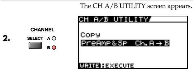
Copying or Swapping PREAMP Settings Between Channels
You can take the PREAMP settings for a particular channel and copy them to another channel, or swap the settings for the two channels.
- WRITE The PATCH COPY screen appears.
| Display | Explanation |
| PreAmp&Sp Ch.A→B | This copies the channel A PREAMP and SPEAKER settings to channel B. |
| PreAmp&Sp Ch.B→A | This copies the channel B PREAMP and SPEAKER settings to channel A. |
| PreAmp&Sp Ch.A←B | This swaps the channel A PREAMP and SPEAKER settings with the channel B settings. |
| Chain Ch.A←B | This swaps the channel A PREAMP and SPEAKER settings with the channel B settings and also swaps the arrangement of channel A and channel B in the FX Chain. |
- The selected function is executed.
Setting the Functions of the Knobs of the Play Screen
You can change the functions of the PARAMETER knobs.
| 1. | SYSTEM | The SYSTEM MENU screen appears. | |
| 2. | Select CONTROL. | ||
| SYSTEM MENU PRESSENTER. CONTROLLER PHRASE LOOP MANUAL SETTING PLAY OPTION CONTROL | |||
| 3. | CATEGORY/ ENTER | The CONTROLLER screen appears. | |
| 4. | Select the SYS KNOB SETTING screen (page 1). | ||
| CONTROLLER 1 1111 SYS KNOB SETTING | |||
| Knob P1:MASTER:Low Knob P2:MASTER:Mid Knob P3:MASTER:High Knob P4:Patch Level | |||
| 5. | Select the parameter knob (Knob P1-P4) whose assignment you want to change. | ||
| 6. | Change the parameter settings. | cf. For information on what settings you can assign, refer to “Display of Parameters You Can Set with SYS KNOB SETTING” (p. 138). | |
| 7. | To change another controller setting, repeat Steps 5-6. | ||
| 8. | EXIT twice. | The Play screen appears. | MEMO CONTROLLER parameters are system parameters. They are saved at the time they are entered, and do not require a Write procedure. |
Using Pedals to Control the Parameters
Using the CTL/EXP Pedal With the Same Functions Assigned at All Times (Pedal Function)
This applies the functions of the CTL pedal, EXP Pedal and EXP PEDAL SW globally to the GT-10.
| 1. | SYSTEM | The SYSTEM MENU screen appears. | |
| 2. | Select CONTROL. | ||
| SYSTEM MENU PresstENTER CONTROLLER PHRASE MANUAL PLAY OPTION CONTROL | |||
| 3. | CATEGORY/ENTER | The CONTROLLER screen appears. | |
| CONTROLLED 1 11111 SYS KNOB SETTING Knob P1: MASTER:Low Knob P2: MASTER:Mid Knob P3: MASTER:High Knob P4: Patch Level | |||
| 4. | Select the controller whose assignment you want to change. | ||
| CONTROLLED 11111 CTL1 PEDAL SETTING Prefernc: Patch Function: Off Min: Off Max: On Src Mode: Toggle | |||
| 5. | Select Prefernc. | ||
| 6. | Set the Prefernc parameter to System. | ||
| 7. | Select the parameter of the chosen controller whose settings you want to change. | ||
| 8. | Change the parameter settings. | cf. For information on what settings you can assign, refer to “Function” (p. 138). | |
| 9. | To change another controller setting, repeat Steps 4-6. | ||
| 10. | EXIT twice. | The Play screen appears. | MEMO CONTROLLER parameters are system parameters. They are saved at the time they are entered, and do not require a Write procedure. |

Example of Setting the Pedal Function
Setting the parameters as shown below in the EXP1 PEDAL SETTING screen enables you to constantly use the GT-10's EXP Pedal as a wah pedal.
| Prefernc: | System |
| Function: | WAH |
| Min: | 0 |
| Max: | 100 |
Setting CTL/EXP Functions Individually in Each Patch (Pedal FX)
This procedure sets the functions for the GT-10's controllers (CTL/EXP Pedal, EXP PEDAL SW) for individual patches.
- Set the Prefernc parameter of the CTL/EXP Pedal and EXP PEDAL SW (p. 137) settings to "Patch."
1.

The MST/PDL FX screen appears.
Select PEDAL/FX.
2.
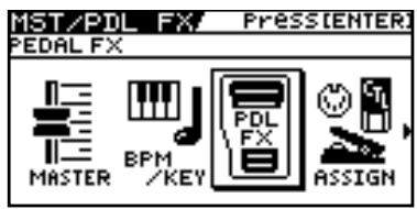
3.
The PDL:CTL/EXP screen appears.

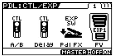
4.
Make the parameter settings.
P1:CTL1 Pedal
P2:CTL2 Pedal
P3: EXP PEDAL SW
P4: EXP Pedal
- To save the settings, use the Write procedure (p. 42).

Pressing [DISPLAY MODE] toggles the display between Knob View and List View.

- Some EXP Pedal parameters use multiple pages for the parameter settings. You can use [ ] and [ ] to switch pages.
Each time [MASTER/PEDAL FX] is pressed, the EXP Pedal functions alternate as shown below.
| Parameter | Functions Switched |
| FV | Foot Volume On/Off |
| PB | Pedal Bend On/Off |
| WAH | Wah On/Off |
| PB/FV | Pedal Bend, Foot Volume |
| WAH/FV | Wah, Foot Volume |
The currently selected setting is the one highlighted at the lower right of the display.

For information on what settings you can assign, refer to "SW&PDL FUNCTION" (p. 122).
TIP
EXP Pedal Function Quick Settings
You can select the Quick Settings by assigning either WAV/FV, PB/FV, WAH, or PB as the EXP Pedal Function.
Selecting these prepared sample settings (Quick Settings) lets you choose optimal values for the related parameters instantly. This allows you to complete the settings simply and easily without the need to set each parameter individually.
- Follow the procedure in "Setting CTL/EXP Functions Individually in Each Patch (Pedal FX)" (p. 48) step 1-3 to display the PDL:CTL/EXP screen.
| 2. | 4 | Select either WAV/FV, PB/FV, WAH, or PB. | |
| 3. | The CONTROLLER EXP1 PEDAL SETTING screen (Page 2) appears. | ||
| POLAROHF IF 20 Quick:---User Setting TYPE :PEDAL MAX EFFECT LEVEL WO WAH 0 100 100 MASTERHOFFON | |||
| 4. | Select the Quick Setting (P01-P08, U01-U10). | cf. For information on what settings you can assign, refer to "SW&PDL FUNCTION" (p. 122). |
| Display | Explanation | |
| Quick:U** | User Quick Settings | |
| Quick:P** | Preset Quick Settings | |
| U01-1-U50-4 | User Patch | MEMO |
| P01-1-P50-4 | Preset Patch | When you select a User patch or Preset patch, you can use the existing patch's assign settings just as they are. |
- To save the settings, use the Write procedure (p. 42).
MEMO
When SYSTEM or CONTROLLER Messages Are Displayed
These appear when the Prefernc parameter for the Controller whose settings you attempted to change (CONTROLLER screen (p. 137)) is set to System.
This means that the settings in the SW&PDF FUNCTION screen, which are the patch parameters, have no effect.
To enable the settings in the SW&PDF FUNCTION screen, set the Prefernc parameter to Patch beforehand.
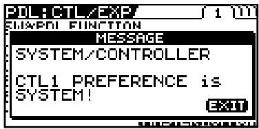
To dismiss this message, press [EXIT].
Setting Each Controller Functions to Individual Patches (Assign)
You can set the CTL/EXP Pedal, EXP PEDAL SW, and external controllers (footswitch and expression pedal) connected to the rear panel's EXP PEDAL 2/CTL 3,4 jacks for each individual patch.
You can save up to eight separate settings per patch (using Assign numbers 1 through 8) that determine what parameters are controlled by which controllers.
- Set the Prefernc parameter of the CTL/EXP Pedal and EXP PEDAL SW (p. 137) settings to "Patch."
Quick Settings
When you select prepared settings (Quick Settings), the relevant parameters are instantly set to their optimal values. This lets you make the settings simply, instead of setting each individual parameter separately.
| 1. | MASTER/PEDAL FX | The MST/PDL FX screen appears. | |
| 2. | Select ASSIGN. | ||
| MST/PDL FX PressEnter ASSIGN BPM /KEY ASSIGN | |||
| 3. | CATEGORY/ENTER | The ASSIGN screen appears. | |
| ASSIGN No.1 | 10000 Quick:---User Setting TARGET COUSET COMP COLD Source CTL On/Off PEDAL 12345678 MASTER:OFFON | |||
| 4. | Select one of the ASSIGN number (No.1-8). | ||
| 5. | MASTER/PEDAL FX | Set the selected Assign number to "On." | MEMO Each time [MASTER/PEDAL FX] is pressed it alternately switches the selected ASSIGN number on and off. When on, the Assign number at the bottom left of the display and the "ON" indication at the bottom right are highlighted. Be sure to set any Assign settings not being used to "Off." |
| 6. | Select the Quick Setting (P01-P08, U01-U10). |
| Display | Explanation | |
| Quick:U** | User Quick Settings | |
| Quick:P** | Preset Quick Settings | |
| U01-1.1-U50-4.8 | User Patch | MEMO |
| P01-1.1-P50-4.8 | Preset Patch | When you select a User patch or Preset patch, you can use the existing patch's assign settings just as they are. |
- To use the Quick Settings with other Assigns, repeat Steps 4-6.
- To save the settings, use the Write procedure (p. 42).
Manual Settings
Here, you can individually determine which controller is to control which parameter.
| 1. | MASTER/ PedAL FX | The MST/PDL FX screen appears. | |
| 2. | Select ASSIGN. | ||
| MST/PDL FX PressEnter ASSIGN | |||
| BPM /KEY PDL FX ASSIGN | |||
| 3. | CATEGORY/ ENTER | The ASSIGN screen appears. | |
| ASSIGN No.1 1 11111 QUICK:---USER SETTING TARGET COUSET COMP ON/Off CTL1 FEDAL | MEMO Each time [MASTER/PEDAL FX] is pressed it alternately switches the selected ASSIGN number on and off. When on, the Assign number at the bottom left of the display and the “On” indication at the bottom right are highlighted. Be sure to set any Assign settings not being used to “Off.” | ||
| 12345678 MASTEROFFON | |||
| 4. | Select one of the ASSIGN number (No.1-8). | ||
| 5. | MASTER/ PedAL FX | Set the selected Assign number to “On.” | |
| Select the controller that you want to edit the parameter. | |||
| 6. | 4 | Select the parameter you wish to control. | |
| 7. | 2 | Select the parameter you wish to control. | You can rapidly select the parameter you want by using the P1 knob to navigate down from the broad category. |
| 8. | To set the other Assigns, repeat Steps 4-7. | Only the TARGET and the SOURCE are shown in Icon View. If you want to have all parameters appear, switch to List View. | |
| 9. | To save the settings, use the Write procedure (p. 42). | ||
Parameters That Can Be Set in ListView
The following describes the parameters that can be set when you switch to ListView in the ASSIGN screen.
The screen that's shown uses ASSIGN No. 1 as an example.
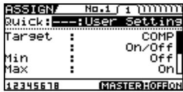
| Parameter | Explanation |
| Target | Use to select the parameter you want to control. |
| Min | This sets the minimum value for the target's controllable range. |
| Max | This sets the maximum value for the target's controllable range. |
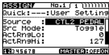
| Parameter | Explanation | |
| Source | This selects the controller assigned to the function. | |
| Src Mode | Moment | The normal state is Off (minimum value), with the switch On (maximum value) only while the footswitch is depressed. |
| Toggle | The setting is toggled On (maximum value) or Off (minimum value) with each press of the footswitch. | |
| ActRngLo | This sets the minimum for the range in which the value of the setting can be changed. | |
| ActRngHi | This sets the maximum for the range in which the value of the setting can be changed. | |
cf.
For more information about each parameter, refer to "ASSIGN 1-8" (p. 126).
About the Range of a Target's Change
The value of the parameter selected as the target changes within the range defined by "Min" and "Max," as set on the GT-10. When using an external footswitch, or other controller that acts as an on/off switch, "Min" is selected with Off (CLOSED), and "Max" is selected with On (OPEN).
When using an external expression pedal or other controller that generates a consecutive change in the value, the value of the setting changes accordingly, within the range set by the minimum and maximum values. Also, when the target is of an on/off type, the median value of the received data is used as the dividing line in determining whether to switch it on or off.
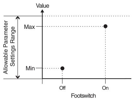
When using the footswitch:
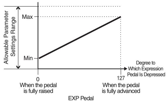
When using the EXP Pedal:
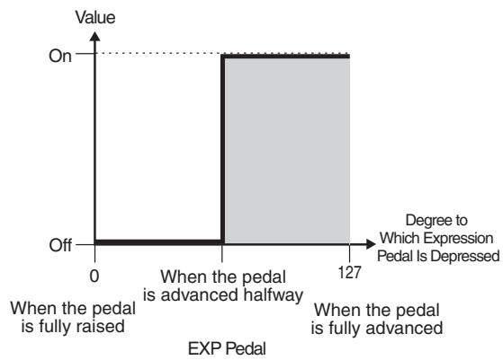
When controlling the On/Off target with the EXP Pedal:
- The range that can be selected changes according to the target setting.
- When the "minimum" is set to a higher value than the "maximum," the change in the parameter is reversed.
- The values of settings can change if the target is changed after the "minimum" and "maximum" settings have been made. If you've changed the target, be sure to recheck the "minimum" and "maximum" settings.
About the Range of a Controller's Change
This sets the operational range within which the value of the setting changes when an EXP Pedal or other controller that changes the value consecutively is used as the source. If the controller is moved outside the operational range, the value does not change, it stops at "minimum" or "maximum."
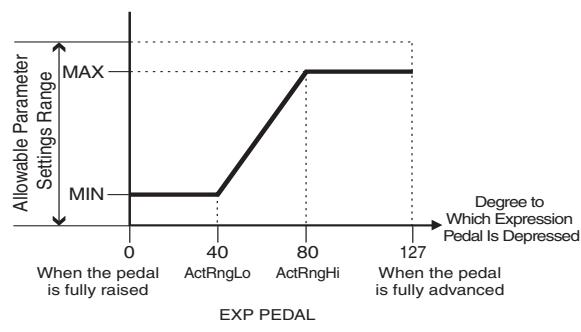
(Example) With ActRngLo: 40, ActRngHi: 80
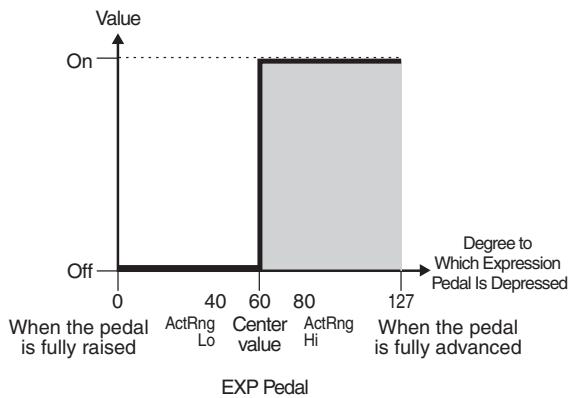
- When using a footswitch or other on/off switching controller as the source, leave these at "ActRngLo: 0" and "ActRngHi: 127." With certain settings, the value may not change.
TIP
Example of Assign Settings
Setting the parameters as shown below enables you to use the GT-10's EXP Pedal as a UNI-V rate parameter.
| Target: | FX1:UV:Rate | Src Mode: | Moment |
| Min: | 0 | ActRngLo: | 0 |
| Max: | 100 | ActRngHi: | 127 |
| Source: | EXP1 PEDAL |
Activating the Virtual Expression Pedal at the Start of Operations (Internal Pedal System)
The GT-10 features a function called Internal Pedal system. This function assigns specified parameters to a virtual expression pedal (the internal pedal), providing an effect that automatically changes volume and tone in real time just the way an expression pedal functions.
The Internal Pedal system features the following two functions, allowing you to set Source for each ASSIGN No.1-8 of the "Manual Settings" (p. 51).
- When the Internal Pedal or the Wave Pedal is used, set the ASSIGN Src Mode to Moment.
Internal Pedal
With the trigger you have set, the assumed expression pedal starts working. If you have set INTERNAL PDL to Source, set the Int Trig parameter.
cf.
For more detailed information on the parameters that can be set using Internal Pedal, refer to "Int Trig (Internal Pedal Trigger)" (p. 126), "Int Time (Internal Pedal Time)" (p. 126), and "IntCurve (Internal Pedal Curve)" (p. 126).
Wave Pedal
This changes the parameter selected as a target in a certain cycle with the assumed expression pedal. When you have set Wave Pedal for Source, the WaveRate and Waveform should be set.
cf.
For more detailed information on the parameters that can be set using Wave Pedal, refer to "WaveRate (Wave Pedal Rate)" (p. 126) and "Waveform (Wave Pedal Form)" (p. 127).
Turning the Effects On and Off with the BANK/Number Pedals (Manual Mode)
The GT-10 features a Manual mode, in which the pedals are used for switching specified effects on and off.
In Manual mode, you can switch effects on and off without changing the patch number.
Switching to Manual Mode
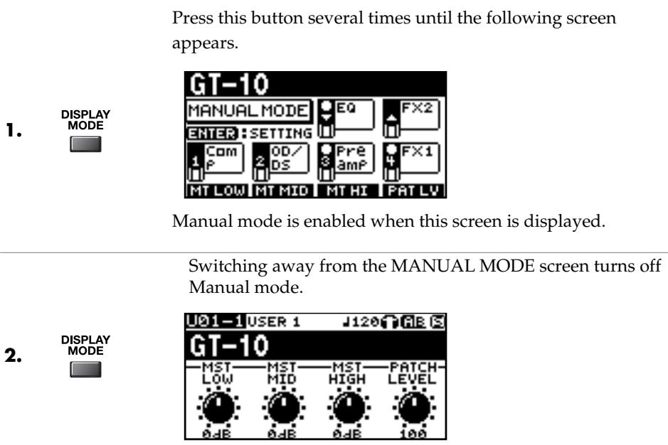
MEMO
- You can press [CATEGORY/ENTER] in this screen to switch to the MANUAL SETTING screen (p. 56).
- Setting the TARGET to Manual Mode Sw in "Manual Settings" (p. 51) enables you to switch Manual mode on and off.
Switching Effects On and Off with the Pedals
- Perform "Switching to Manual Mode" (p. 55), to turn Manual mode on.
- 1e3. The pedal switches the assigned effect on or off.
MEMO
The assigned effect is switched on or off with each press of the pedal. When the assigned effect is on, the indicator at the top of the pedal lights up.
Assigning an Effect On/Off Switch to a Pedal
| 1. | SYSTEM | The SYSTEM MENU screen appears. | MEMO You can also enter the MANUAL SETTING screen from the Play screen (p. 55). |
| 2. | Select MANUAL SETTING. | ||
| SYSTEM MENU Pressienter MANUAL MODE SETTING PHRASE LOOP MANUAL SETTING PLAY OPTION CONTROL | |||
| 3. | CATEGORY/ENTER | The MANUAL SETTING screen appears. | |
| MANUAL SETTING MANUAL MODE SETTING EQ FX2 1 Com 2 OD/ DS Preamp FX1 3 | |||
| 4. | Select the pedal whose assignment you want to change. | ||
| 5. | Select the effect switch you want to assign to the pedal. | ||
| 6. | To change another pedal setting, repeat Steps 4-5. | ||
Assignable Effect Switches
| Display | Explanation |
| Off | The function is not assign to the pedals. |
| Ch.A/B | Switches between Preamp channel A and B. |
| OD Sol | Switches OD/DS SOLO on and off. |
| Solo | Switches Preamp SOLO on and off. |
| A&BSol | Switches the preamp SOLO, for both channel A and B, on and off. If one of the two channels is off, both will be turned on. |
| Comp | Switches the COMP on and off. |
| OD/DS | Switches the OD/DS on and off. |
| Preamp | Switches the PREAMP/SPEAKER on and off. |
| EQ | Switches the EQ on and off. |
| FX1 | Switches FX-1 on and off. |
| FX2 | Switches FX-2 on and off. |
| Delay | Switches the DELAY on and off. |
| Chorus | Switches the CHORUS on and off. |
| Reverb | Switches the REVERB on and off. |
| PdlFX | Switches the Pedal FX on and off. |
| S/R | Switches the SEND/RETURN on and off. |
| AmpCTL | Switches the Amp Control on and off. |
| Tuner | Switches the TUNER/BYPASS on and off. |
| Display | Explanation |
| PL | Switches the PHRASE LOOP on and off. |
| PL R/P | Records/plays back the phrase. |
| PL Clr | Cleared the phrase. |
| PL M/P | Mutes playback of the phrase. |
| BPMTap | Used for tap input of the Master BPM. |
| DlyTap | Used for tap input of the delay time. |
| MIDI | Controls the Start/Stop of external MIDI devices (such as sequencers). |
| MMCPly | Controls the Play/Stop of external MIDI devices (such as hard disk recorders). |
| Lev+10 | Increases the patch volume level by 10 units. |
| Lev+20 | Increases the patch volume level by 20 units. |
| Lev -10 | Decreases the patch volume level by 10 units. |
| Lev -20 | Decreases the patch volume level by 20 units. |
| NumInc | Switches to the next higher patch number in the same bank as the currently selected patch. |
| NumDec | Switches to the next lower patch number in the same bank as the currently selected patch. |
| BnkInc | Switches to the next higher bank number. |
| BnkDec | Switches to the next lower bank number. |
Switching Settings with the Number Pedals
The GT-10 includes a function that allows you to turn the tuner on and off, switch preamp channels, and perform other tasks by pressing the pedal with the same number as the currently selected patch.
MEMO
You can switch the following functions in any condition other than the Manual Mode.
| 1. | SYSTEM | The SYSTEM MENU screen appears. | |
| 2. | Select PLAY OPTION. | ||
| SYSTEM MENU PresstENTER PLAY OPTION PHRASE LOOP MANUAL SETTING PLAY OPTION CONTROL | |||
| 3. | CATEGORY/ENTER | The PLAY OPTION screen appears. | |
| 4. | Select Num Pdl Sw. | ||
| PLAY OPTION BankExtentMin: U01 BankExtentMax: P50 EXP Pd1 Hold: Off Pd1 Indicate: Off Num Pd1 Sw: Off Dial Func: Pat&Val | |||
| 5. | Set the Num Pdl Sw Parameter. |
| Display | Explanation |
| Off | Not used. |
| Tuner | Switches the tuner on and off. |
| Ch. A/B | Switches between preamp channels A and B. |
| OD Solo | Switches to tones suited to solo performance. |
| Solo | Switches the preamp SOLO on and off. |
| AB Solo | Switches SOLO on or off for both preamp channels A and B. |
Phrase Loop Play
What's Phrase Loop?
In this mode, you can record up to 38 seconds of material (recorded in mono) and repeatedly play material as a "phrase loop." As the loop plays, you can overdub new material if desired.
You can record a phrase loop with effects, or you can add effects after a loop has been recorded. Adding effects after-the-fact lets you create special effects with recorded performances. It's also a great way to audition tones, as you can adjust effect parameters in real time while a phrase plays back.
Using the Phrase Loop
Recording a Phrase (REC)
| 1. | Press [BANK▼] and [BANK▲] at the same time. The unit goes into recording standby (The REC/DUB indicator flashes). | MEMO Simultaneously pressing these a second time stops loop playback and switches Phrase Loop off. |
| 2. | Recording starts. (The REC/DUB indicator lights up.) Play the phrase you want to record. | MEMO The maximum recording time for monaural recording is approximately 38 seconds. When the recording time reaches 38 seconds, playback of the recorded performance starts automatically. |
| 3. | Recording stops. (The REC/DUB indicator goes out.) The recorded phrase is looped (played repeatedly). (The PLAY indicator lights up.) |
Over dubbing Sound onto a Phrase (DUB)
- Follow the procedure in "Recording a Phrase (REC)" (p. 58) to record a phrase, then perform loop play. (The PLAY indicator lights up.)
OVERdubbing starts. (The REC/DUB indicator lights up.) 2. Play the phrase you want to overdub along with the playback of the loop.
Overdubbing stops. (The REC/DUB indicator goes out.)
The phrase you just recorded is combined with the phrase you recorded first and that sound is automatically played in a loop. (The PLAY indicator lights up.)
TERM
Recording on top of an existing performance is called "overdubbing."
MEMO
If you want to overdub additional material, repeat steps 2 and 3.
Deleting a Phrase (CLEAR)
The procedure for deleting a phrase differs according to the setting of the Clear Pdl parameter.

For information on the Clear Pdl parameter, refer to "Clear Pdl (Clear Pedal Function)" (p. 60).
| When the Clear PdI parameter is “Clear Only” | When the Clear PdI parameter is “Mute/Clear” | ||
| 1. | The phrase is deleted and the unit goes into recording standby. | 1. | Pressing this during recording stops recording and puts the unit in muted playback. (The PLAY indicator flashes.) No sound is produced, but loop play continues inside the GT-10. Pressing [BANK▼] while the unit is muted enables normal loop playback. (The PLAY indicator lights up.) |
| 2. | Pressing this while the sound is muted deletes the phrase and puts the unit in recording standby. | ||
Setting Phrase Loop
You can also enable different uses by changing the parameters.
| 1. | SYSTEM | The SYSTEM MENU screen appears. | |
| 2. | Select PHRASE LOOP. | ||
| SYSTEM MENU / PressEnter PHRASE LOOP PHRASE LOOP MANUAL SETTING PLAY OPTION CONTROL | |||
| 3. | CATEGORY/ENTER | The PHRASE LOOP screen appears. | |
| PHRASE LOOP Mode :Performance Pd1 Mode :Off Rec Mode :Mono Play Lev :100 Clear Pd1: Clear Only (ENTER:OFF) | |||
| 4. | Move the cursor to select the parameter you wish to change. | ||
| 5. | Change the parameter settings. |
| Parameter/ Range | Explanation |
| Mode | |
| Performance | This records the sound after it passes through the effects. This lets you achieve a rich variety of performances by combining different tones. |
| Patch Edit | This records the sound before it passes through the effects, and applies the effects during loop play. This enables you to adjust effects or compare patch tones. |
Chapter 4 Playing Sounds
| Parameter/Range | Explanation |
| Pdl Mode (Pedal Mode) | |
| Off | The BANK pedals are not used for operation of the Phrase Loop feature. These are used as bank switch pedals.TIPPhrase Loop can be controlled by assigning the Phrase Loop feature to any of the CTL pedals 1 through 4 and maintaining the BANK pedals' bank switching function. |
| On | The BANK pedals are used for operation of the Phrase Loop feature. |
| Rec Mode (Recording Mode) | |
| Mono | Phrases are recorded in mono (max. 38 seconds). |
| Stereo | Phrases are recorded in stereo (max. 19 seconds). |
| Play Lev (Play Level) | |
| 0-120 | Sets the phrase playback volume. |
| Clear Pdl (Clear Pedal Function) | |
| Clear Only | When you press [BANK▲] while the Phrase Loop feature is on, the recorded data is cleared and then GT-10 switches to STANDBY mode. |
| Mute/Clear | When you press [BANK▲] while the Phrase Loop feature is on, the performance of the recorded phrase is muted (the recorded data is not erased).If you then press [BANK▲] again while the phrase is muted, the recorded data is cleared and then GT-10 switches to STANDBY mode. |
Overview of Phrase Loop Operation
When the PHRASE LOOP function and the Pdl Mode parameter are both set to "on," phrase loop operation is switched as shown below.
When the Clear Pdl parameter is "Clear Only"
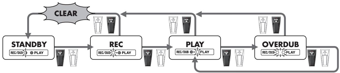
When the Clear Pdl parameter is "Mute/Clear"
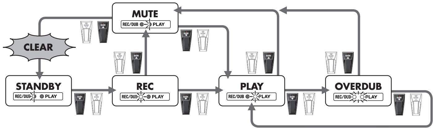
Making Settings Matched to the Connected Guitar (Input Select)
The GT-10 includes a feature for adjusting the tone to suit whatever guitar you have connected, allowing you to make settings for three guitar types (Guitar 1-3). This is effective when you are connecting a different guitar from the one used when the patch was created.
NOTE
When adjusting the input level and input presence, the input signals for all patches are affected. Note that the nuances of the effect sounds that occur in response to guitar volume may change, particularly with patches in which effects are controlled by the guitar volume.
SYSTEM The SYSTEM MENU screen appears.
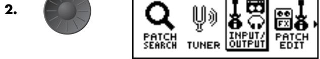
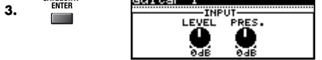
Select INPUT/OUTPUT.
4. Select the INPUT SELECT (Guitar 1-3) you want to set.
P2 knob: Adjusts the guitar input level.
P3 knob: Adjusts the tonal quality of the guitar's high end.
MEMO
Select USB In when you're inputting audio from a computer via USB (p. 134).
cf.
For information on the parameters, refer to "INPUT" (p. 134).
Adjusting the Overall Sound to Match the Usage Environment (Global)
The GT-10 includes a feature that allows you to change the overall tone of all patches. This is called the "Global function."
With the Global function, you can change your settings to match those of your equipment and the operating environment, while leaving the settings in the patches untouched.
Adjusting the Overall Tone (Global EQ)
This adjusts the tone of the OUTPUT regardless of the equalizer on/off settings of individual patches.
| 1. | SYSTEM | The SYSTEM MENU screen appears. | |
| 2. | Select INPUT/OUTPUT. | ||
| SYSTEM MENU PressEnter INPUT/OUTPUT PATCH SEARCH TUNER | |||
| 3. | CATEGORY/ ENTER | The INPUT/OUTPUT screen appears. | |
| 4. | Select the GLOBAL EQ (page 2) screen. | ||
| INPUT/OUTPUT 1/2 GLOBAL EQ Low Gain: 0dB Mid Gain: 0dB Mid Freq: 800Hz Mid Q: 1 High Gain: 0dB | |||
| 5. | Move the cursor to the parameter you want to set. | ||
| 6. | Adjust the parameter. | cf. For information on the parameters, refer to “GLOBAL EQ” (p. 134). |
| Parameter | Explanation |
| Low Gain | Adjusts the low frequency range tone. |
| Mid Gain (Middle Gain) | Adjusts the middle frequency range tone. |
| Mid Freq (Middle Frequency) | Specifies the center of the frequency range that will be adjusted by the MID GAIN. |
| Mid Q (Middle Q) | Adjusts the width of the area affected by the EQ centered at the MID FREQ. Higher values will narrow the area. |
| High Gain | Adjusts the high frequency range tone. |
Controlling the Overall Effect of the Noise Suppressor (Total Noise Suppressor)
This controls the overall threshold value for the noise suppressor settings in the individual patches. This is an effective tool when guitars are changed during performances and for making adjustments in response to noise levels at the performance venue.
This is an overall setting and does not alter the individual patch settings.
MEMO
This has no effect on patches in which the noise suppressor is turned off.
| 1. | SYSTEM | The SYSTEM MENU screen appears. | |
| 2. | Select INPUT/OUTPUT. | ||
| SYSTEM MENU PresstENTER INPUT/OUTPUT | |||
| PATCH SEARCH TUNER | INPUT/OUTPUT PATCH EDIT | ||
| 3. | CATEGORY/ ENTER | The INPUT/OUTPUT screen appears. | |
| 4. | Select the TOTAL (page 3) screen. | ||
| INPUT/OUTPUT | |||
| TOTAL | |||
| NS Threshold: 0dB | |||
| Rev Level: 100% | |||
| USB/DGT Out Lev: 100% | |||
| USB Mix Level: 100% | |||
| Main Out Level: -10dB | |||
| 5. | Move the cursor to NS Threshold. | ||
| 6. | Adjust the threshold level of the Noise Suppressor. | MEMO Set to “0 dB” when using this in individual patch settings. cf. For information on the parameters, refer to “NS Threshold (Noise Suppressor Threshold)” (p. 135). | |
Controlling the Overall Reverb Level (Total REVERB)
This controls the overall reverb level settings in the individual patches. This is effective for adjusting to the acoustics of the performance venue.
This setting does not affect the individual patch settings.

This has no effect on patches in which the reverb is turned off.
| 1. | SYSTEM | The SYSTEM MENU screen appears. | |
| 2. | Select INPUT/OUTPUT. | ||
| SYSTEM MENU PressEnter INPUT/OUTPUT | |||
| PATCH SEARCH TUNER | INPUT/ OUTPUT PATCH EDIT | ||
| 3. | CATEGORY/ ENTER | The INPUT/OUTPUT screen appears. | |
| 4. | Select the TOTAL (page 3) screen. | ||
| INPUT/OUTPUT 0f3 TOTAL | |||
| NS Threshold: 0dB Rev Level: 100% USB/DGT Out Level: 100% USB Mix Level: 100% Main Out Level: -10dB | |||
| 5. | Move the cursor to Rev Level. | ||
| 6. | Adjust the reverb level. | MEMO Set to "100%" when using this in individual patch settings. cf. For information on the parameters, refer to "Rev Level (Reverb Level)" (p. 135). |
Setting the Output Reference Level to Match the Connected Equipment (Main Out Level)
This sets the output reference level to match the equipment connected to the OUTPUT jack.
| 1. | SYSTEM | The SYSTEM MENU screen appears. | |
| 2. | Select INPUT/OUTPUT. | ||
| SYSTEM MENU PressEnter INPUT/OUTPUT | |||
| PATCH SEARCH TUNER | INPUT/ OUTPUT PATCH EDIT | ||
| 3. | CATEGORY/ ENTER | The INPUT/OUTPUT screen appears. | |
| 4. | Select the TOTAL (page 3) screen. | ||
| INPUT/OUTPUT | |||
| TOTAL | |||
| NS Threshold: 0dB | |||
| Rev Level: 100% | |||
| USB/DGT Out Lev: 100% | |||
| USB Mix Level: 100% | |||
| Main Out Level: -10dB | |||
| 5. | Move the cursor to Main Out Level. | ||
| 6. | Adjust the reference level. |
| Value | Explanation |
| -10dB | Choose this when connected to a guitar amp. |
| +4dB | Choose this when connected to a recorder, mixer, or other line device. |
Adjusting the Output Level of the DIGITAL OUT Jack
You can adjust the level of the audio signals output from the DIGITAL OUT jack.
Digital signals are output from the DIGITAL OUT jack on the rear panel. You can connect this directly to the digital in connector of a digital recorder or other device and record with no degradation in sound quality.
The same digital audio signals are output from DIGITAL OUT and USB.
| 1. | SYSTEM | The SYSTEM MENU screen appears. | |
| 2. | Select INPUT/OUTPUT. | ||
| SYSTEM MENU PresstENTER. INPUT/OUTPUT PATCH SEARCH TUNER | INPUT/PATCH OUTPUT/PATCH EDIT | ||
| 3. | CATEGORY/ ENTER | The INPUT/OUTPUT screen appears. | |
| 4. | Select the TOTAL (page 3) screen. | ||
| INPUT/OUTPUT (if 3) TOTAL NS Threshold : 0dB Rev Level : 100% USB/DGT Out Lev : 100% USB Mix Level : 100% Main Out Level : -10dB | |||
| 5. | Move the cursor to USB/DGT Out Lev. | ||
| 6. | Adjust the level. | . | |
Adjusting the Display Contrast (LCD Contrast)
Depending on where the GT-10 is placed, the display (on the right) may become difficult to read. If this occurs, adjust the display contrast.
SYSTEM The SYSTEM MENU screen appears. 1.
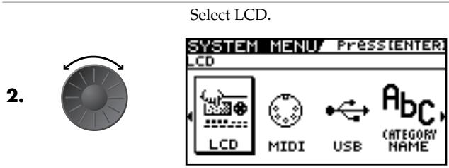
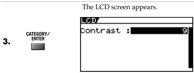
Keeping Effect Sounds Playing After Patches Are Switched (Patch Change Mode)
The GT-10 features a mode that is enabled when spatial effects (such as reverb and delay) are used, whereby the effects sound of one patch continues playing even after you switch to the next patch. If the necessary following conditions regarding the effects chain and effect parameter settings are met, you can then have the decay of reverb, delay, and similar effects continue on into the next patch after you switch patches.
- Effects are in the same effects chain
- When switching the delay off or on, or when the Type parameter and Dly Time parameter are identical
- When switching other effects off or on, or when the parameter settings are identical
MEMO
There still may be no reverberation in some cases, even after the above settings are made.
| 1. | SYSTEM | The SYSTEM MENU screen appears. | |
| 2. | Select PLAY OPTION. | ||
| SYSTEM MENU PressEnter PLAY OPTION PHRASE MANUAL SETTING PLAY OPTION CONTROL | |||
| 3. | CATEGORY/ENTER | The PLAY OPTION screen appears. | |
| 4. | Move the cursor to Patch ChgMode. | ||
| PLAY OPTION Preamp Mode: Patch Patch ChgMode: Fast Bank Chg Mode: Wait BankExtentMin: U01 BankExtentMax: P50 EXP Pd1 Hold: Off | |||
| 5. | Select the value of the Patch ChgMode parameter. |
| Value | Explanation |
| Fast | Patches are changed normally. The unit switches to the subsequent patch without any carry-over of the decay from the previous patch's reverb or delay. |
| Smooth | The unit switches to the subsequent patch with the decay from the previous patch's reverb or delay continued after the switch is made. MEMO To ensure smooth switching, the patches may be switched with a delay of one tempo beat. |
Using the Identical Preamp Settings in All Patches (Preamp Mode)
With the GT-10, you can have a preamp be set globally for use in all patches, allowing you to make settings for three preamp types.
This provides an effect that always gives you the sound of the same guitar amp regardless of the patches you set.
Using the System Preamp
1.

The SYSTEM MENU screen appears.
2.
Select PLAY OPTION.
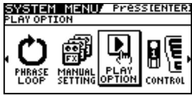
3.

The PLAY OPTION screen appears.
4.

Move the cursor to Preamp Mode.
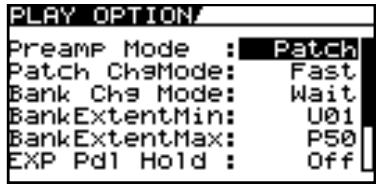
5.

Select the value of the Preamp Mode parameter you want to set.
| Value | Explanation |
| Patch | The patch preamp setting is used. This allows you to use different preamp settings in each individual patch. |
| System1-3 | The system's preamp setting is used. This applies the same preamp settings to all patches. |
Setting the System Preamp
When Preamp Mode is System1 through System3, the changed preamp setting is saved as the system's preamp setting.
The stored content is updated each time the settings are changed.
Saving the Current Preamp Setting As the System's Preamp Setting
You can save the current preamp setting as a preamp setting for the system (System1 through System3).
| 1. | WRITE | The PATCH COPY screen appears. | MEMO When edits have been made to the currently selected patch, the PATCH WRITE screen is displayed. |
| 2. | Select the SYS PREAMP WRITE screen. | ||
| SYS PREAMP WRITE 4 Write to System1 WRITE:EXECUTE | |||
| 3. | Select the save-destination system preamp (System1-3). | MEMO To cancel the Write procedure, press [EXIT]. The Play screen returns to the display. | |
| 4. | WRITE | The settings are saved. |
Limiting the Banks That Can Be Switched (Bank Extent)
By setting an limit to the range of banks that can be switched, you can set the GT-10 so that only the patches you need can be selected.
| 1. | SYSTEM | The SYSTEM MENU screen appears. | |
| 2. | Select PLAY OPTION. | ||
| SYSTEM MENU PRESS ENTER PLAY OPTION FRONT PHRASE LOOP MANUAL SETTING CONTROL | |||
| 3. | CATEGORY/ ENTER | The PLAY OPTION screen appears. | |
| 4. | Move the cursor to BankExtentMin. | ||
| PLAY OPTION Preamp Mode: Patch Patch Ch3Mode: Fast Bank Ch3 Mode: Wait BankExtentMin: U01 BankExtentMax: P50 EXP Pd1 Hold: Off | |||
| 5. | Set the lower limit for the banks. | ||
| 6. | Move the cursor to BankExtentMax. | ||
| 7. | Set the upper limit for the banks. |
Setting the Timing Used for Switching Patches (Bank Change Mode)
This sets the timing with which the GT-10 switches to the next patch when switching banks with the pedals.
| 1. | SYSTEM | The SYSTEM MENU screen appears. | |
| 2. | Select PLAY OPTION. | ||
| SYSTEM MENU PressEnter PLAY OPTION PHRASE MANUAL SETTING PLAY OPTION CONTROL | |||
| 3. | CATEGORY/ENTER | The PLAY OPTION screen appears. | |
| 4. | Move the cursor to Bank Chg Mode. | ||
| PLAY OPTION Preamp Mode: Patch Patch ChgMode: Fast Bank Chg Mode: NET BankExtentMin: U01 BankExtentMax: P50 EXP Pdl Hold: Off | |||
| 5. | Set the timing for switching patches. |
| Value | Explanation |
| Wait | Although the indication in the display is updated to reflect the change in the bank when a BANK pedal is pressed, the patch will not change. The patch changes when a number pedal is pressed. |
| Immed | The patch switches instantly when a BANK pedal or any of the number pedals is pressed. |
Having Values from an EXP Pedal Carried Over When Patches are Called Up (EXP Pedal Hold)
This setting determines whether or not the EXP Pedal operational status is carried over to the next patch when patches are switched.
MEMO
EXP Pedal Hold does not function if the Assign Source mode is set to Toggle (whereby the value is toggled between Min and Max each time the pedal is pressed).
| 1. | SYSTEM | The SYSTEM MENU screen appears. | |
| 2. | Select PLAY OPTION. | ||
| SYSTEM MENU PressEnter PLAY OPTION PHRASE MANUAL SETTING PLAY OPTION CONTROL | |||
| 3. | CATEGORY/ ENTER | The PLAY OPTION screen appears. | |
| 4. | Move the cursor to EXP Pdl Hold. | ||
| PLAY OPTION Preamp Mode: Patch Patch ChsMode: Fast Bank Chs Mode: Wait BankExtentMin: U01 BankExtentMax: P50 EXP Pdl Hold: Off | |||
| 5. | Set whether EXP Pedal Hold is used or not. |
| Value | Explanation |
| Off | The EXP Pedal status is not carried over. (Example) If a patch is switched while the volume is being controlled with an EXP Pedal, the volume of the subsequent patch is adjust to the value set in that patch. If the EXP Pedal is operated, and that information is transmitted to the GT-10, the volume will change in accord with the pedal's movement. |
| On | The EXP Pedal status is carried over. (Example) If a patch is switched while the volume is being controlled with the EXP Pedal, the volume of the subsequent patch will take on the value determined by the current pedal position (angle). If the patch switched to has the EXP Pedal controlling the wah effect, then the volume assumes the value set in the patch, and the patch's wah effect is given the value derived from the current pedal position (angle). |
Switching How the Pedal Indicators Light (Pedal Indicate)
You can have all unlit pedal indicators flash faintly instead.
This makes it easier to locate pedal positions on stage and in other darkened environments.
| 1. | SYSTEM | The SYSTEM MENU screen appears. | |
| 2. | Select PLAY OPTION. | ||
| SYSTEM MENU PressEnter: PLAY OPTION PHRASE MANUAL SETTING PLAY OPTION CONTROL | |||
| 3. | CATEGORY/ENTER | The PLAY OPTION screen appears. | |
| 4. | Move the cursor to Pdl Indicate. | ||
| PLAY OPTION BankExtentMin: U01 BankExtentMax: P50 EXP Pd1 Hold: Off Pd1 Indicate: Off Num Pd1 Sw: Off Dial Func: Pat&Val | |||
| 5. | Set whether Pedal Indicate function is used or not. |
| Value | Explanation |
| Off | The Pedal Indicator function is not use. |
| On | All unlit pedal indicators flash. |
Selecting the Dial Function (Dial Function)
This setting determines whether or not rotating the dial switches the patches.
| 1. | SYSTEM | The SYSTEM MENU screen appears. | |
| 2. | Select PLAY OPTION. | ||
| SYSTEM MENU PressEnter PLAY OPTION PHRASE MANUAL SETTING PLAY OPTION CONTROL | |||
| 3. | CATEGORY/ENTER | The PLAY OPTION screen appears. | |
| 4. | Move the cursor to Dial Func. | ||
| PLAY OPTION BankExtentMin: U01 BankExtentMax: P50 EXP Pd1 Hold: Off Pd1 Indicate: Off Num Pd1 Sw: Off Dial Func: Pet&V31 | |||
| 5. | Select the dial function. |
| Value | Explanation |
| Pat&Val | The dial is used both for switching patches and changing the value of settings. In addition to switching patches with the pedals, you can also switch them by rotating the dial. |
| Value | The dial is used only for changing the values of settings. |
Restoring the Factory Settings (Factory Reset)
Restoring the GT-10 to the settings made at the factory is referred to as a "Factory Reset."
Not only can you return all of the settings to the values in effect when the GT-10 was shipped from the factory, you can also specify the range of settings to be reset.
| 1. | SYSTEM | The SYSTEM MENU screen appears. | |
| 2. | Select FACTORY RESET. | ||
| SYSTEM MENU Press ENTER FACTORY RESET | |||
| PDL CALI-BRATION FACTORY RESET | |||
| 3. | CATEGORY/ENTER | The FACTORY RESET screen appears. | |
| FACTORY RESET SYSTEM ~ U50-4 ENTER:START | |||
| 4. | Set the range for the Factory Reset (Refer to the following table). | ||
| FACTORY RESET SYSTEM ~ U50-4 ENTER START | |||
| The range of data you wish to factory reset |
| Value | Explanation |
| System | System parameter settings |
| Quick | Settings for User Quick Setting 1-10 |
| U01-1-U50-4 | Settings for Patch Number U01-1 through U50-4 |
- Category/ The specified range of parameters are returned to their original factory settings.
Adjusting the EXP Pedal
Although the GT-10's EXP Pedal has been set for optimum operation at the factory, extended use and the operating environment can result in the pedal going out of adjustment.
If you encounter problems such as being unable to fully cut off the sound with the volume pedal or being unable to switch the EXP PEDAL SW, you can use the following procedure to readjust the pedal.
| 1. | SYSTEM | The SYSTEM MENU screen appears. | |
| 2. | Select PDL CALIBRATION. | ||
| SYSTEM MENU Press [ENTER] | |||
| PEDAL CALIBRATION | |||
| PDL CALIBRATION FACTORY RESET | |||
| 3. | The PEDAL CALIBRATION screen appears. | ||
| PEDAL CALIBRATION Set Pedal to Min Then, Press [ENTER] | |||
| 4. | Depress the heel of the EXP Pedal. | ||
| 5. | The message “OK” appears, and then the following screen is displayed. | MEMO If you press [CATEGORY/ENTER] without pressing down on the heel of the EXP Pedal or with an inappropriate EXP Pedal value (angle), “Area Over” appears in the display, and you are prevented from proceeding to the next step. Readjust the pedal position. | |
| PEDAL CALIBRATION Set Pedal to Max Then, Press [ENTER] | |||
| 6. | Depress the toe of the EXP Pedal. | ||
| 7. | The message “OK” appears, and then the following screen is displayed. | MEMO If you press [CATEGORY/ENTER] without pressing down on the toe of the EXP Pedal or with an inappropriate EXP Pedal value (angle), “Area Over” appears in the display, and you are prevented from proceeding to the next step. Readjust the pedal position. | |
| PEDAL CALIBRATION Test Pedal SW Thres: B Then, Press [ENTER] |
Chapter 5 Making Global Settings
8.

Firmly depress the toe of the EXP Pedal.
9.

Repeat steps 8 and 9 to adjust the Thres parameter so that the EXP PEDAL SW indicator lights up and goes out with appropriate depression force.
10.

The sensitivity of the PEDAL SW is calibrated.
Chapter 6 Using the GT-10 with External MIDI Devices Connected
What Can You Do with MIDI?
You can perform the following operations using MIDI with the GT-10.
MEMO
The use of MIDI requires that the MIDI channels of the connected devices match. If the MIDI channel settings are not correct, the GT-10 will be unable to exchange data with other MIDI devices.
Operating From the GT-10
Outputting Program Change Messages
When a patch is selected on the GT-10, a Program Change message corresponding to the patch number is transmitted simultaneously. The external MIDI device then switches its settings according to the Program Change message it receives.
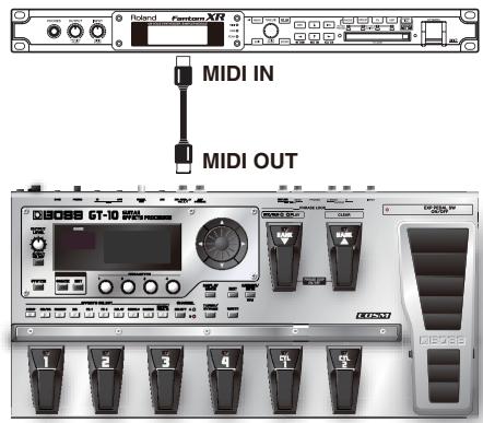
Outputting Control Change Messages
Data describing the actions of the CTL pedal, EXP Pedal, EXP PEDAL SW, and external devices connected to the EXP PEDAL 2/CTL 3, 4 jack are output as Control Change messages. Such messages can be used to (among other things) manipulate the parameters of an external MIDI device.
Transmitting Data
You can use Exclusive messages to transmit the settings for effect sounds and other content stored in the GT-10 to other MIDI devices. For example, you can provide another GT-10 with the same settings, and save effect sound settings to a sequencer or other device.
Remotely Controlling the GT-10 Using an External MIDI Device
Switching Patch Numbers
When the GT-10 receives Program Change messages from the external MIDI device, its patches are simultaneously switched.
MEMO
You can set up the correspondence between MIDI Program Change messages and the GT-10's patches using the Program Change Map (p. 84). You may need to work on these correspondences when you want to line up some effects in combination with other MIDI devices.
The connections shown in the figure below are for a sequencer automatically performing the backing as a guitar is being played. The patches are switched automatically when the program numbers corresponding to the patches are input along with the performance data at the points where you have determined the GT-10 patches are to be switched.
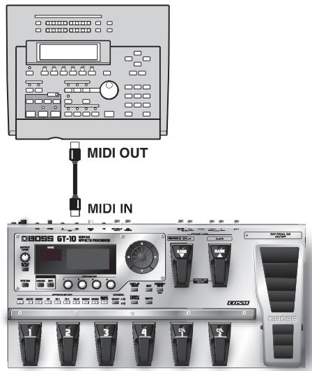
Receiving Control Change Messages
MEMO
You can control specified parameters during a performance by having the GT-10 receive Control Change messages. Parameters to be controlled are set with "Manual Settings" (p. 51).
Receiving Data
The GT-10 can receive data transmitted from another GT-10, as well as data that's been stored on a sequencer.
Exchanging MIDI Messages between the Computer and the GT-10
If you set the GT-10 into the specialized driver mode and connect it to your PC/Mac by a USB cable, you can transfer MIDI message bidirectionally via USB. Set your computer MIDI input and output ports to "GT-10."
If you set USB connection between the GT-10 and PC/Mac, MIDI message transfer via MIDI connectors become inactivated.
Making the Settings for MIDI Functions
Here is a description of the GT-10's MIDI functions. Set them as needed, depending on the intended use.
| 1. | SYSTEM | The SYSTEM MENU screen appears. | |
| 2. | Select MIDI. | ||
| SYSTEM MENU PressiENTER MIDI LCD MIDI USB ABC CATEGORY NAME | |||
| 3. | CATEGORY/ ENTER | The MIDI MENU screen appears. | |
| 4. | Select SETTING. | ||
| MIDI Menu PressiENTER SETTING PROGRAM MAP B.DUMP | |||
| 5. | CATEGORY/ ENTER | The SETTING screen appears. | |
| MIDI SETTING Rx Channel 1 Omni Mode 1 Tx Channel 1 Device ID 1 Sync Clock Auto | |||
| 6. | Select the parameter. | ||
| 7. | Change the setting's value. | MEMO Set each parameter as necessary. For details on these settings, refer to the following sections. |
Setting the MIDI Receive Channel
This sets the MIDI channel used for receiving MIDI messages.
- Follow the procedure in "Making the Settings for MIDI Functions" (p. 80) to move the cursor to "Rx Channel."
- Set the desired value.
1-16
Setting the MIDI Omni Mode
This makes the settings for the channels used for MIDI information.
- Follow the procedure in "Making the Settings for MIDI Functions" (p. 80) to move the cursor to "Omni Mode."
- Set the desired value. Omni On Messages are received on all channels, regardless of the MIDI channel settings.

Omni Off
Information is received on the channel specified by the Rx Channel setting.
MEMO
Even when Omni Mode is set to "Omni On", the only Exclusive messages received are for Device ID data set with "Device ID."
Setting the MIDI Transmit Channel
This sets the MIDI channel used for transmitting MIDI messages.
- Follow the procedure in "Making the Settings for MIDI Functions" (p. 80) to move the cursor to "Tx Channel."
- Set the desired value.

1-16,Rx
MEMO
- When set to "Rx," this MIDI channel is same as the MIDI Receive channel.
Setting the MIDI Device ID
This sets the MIDI Device ID used for transmitting and receiving Exclusive messages.
- Follow the procedure in "Making the Settings for MIDI Functions" (p. 80) to move the cursor to "Device ID."
- Set the desired value.

1-32
Setting the MIDI Sync Clock
This setting determines the basis used for synchronizing the timing for effect modulation rates and other time-based parameters.
- Follow the procedure in "Making the Settings for MIDI Functions" (p. 80) to move the cursor to "Sync Clock."
| 2. Set the desired value. | Auto | Operations are synchronized to the MIDI Clock received via MIDI. However, operations are automatically synchronized to the GT-10's internal Clock if the GT-10 is unable to receive the external Clock. |

Internal
Operations are synchronized to the GT-10's internal Clock.
NOTE
- When you have an external MIDI device connected, the Master BPM is then synchronized to the external MIDI device's tempo, thus disabling the Master BPM setting. To enable setting of the Master BPM, set to "Internal."
- When synchronizing performances to the MIDI Clock signal from an external MIDI device, timing problems in the performance may occur due to errors in the MIDI Clock.
Sending Program Change Messages
This setting determines whether or not Program Change messages are output when patches are switched on the GT-10.
- Follow the procedure in "Making the Settings for MIDI Functions" (p. 80) to move the cursor to "PC Out."
- Set the desired value. Off Program Change messages are not output, even when patches are switched.

On
Program Change messages are simultaneously output when patches are switched.
MEMO
- On the GT-10, Bank Select messages are output simultaneously with Program Change messages. For more details, refer to p. 85.
Sending EXP Pedal Operations as Control Change Messages
This sets the controller number when EXP Pedal operation data is output as Control Change messages.
- Follow the procedure in "Making the Settings for MIDI Functions" (p. 80) to move the cursor to "EXP1 Out."
- Set the desired value. Off Control Change messages are not output.

CC#1-CC#31, CC#64-CC#95
This sets the controller number when EXP Pedal operation data is output as Control Change messages.
Sending EXP Pedal Sw Operations as Control Change Messages
This sets the controller number when EXP PEDAL SW operation data is output as Control Change messages.
- Follow the procedure in "Making the Settings for MIDI Functions" (p. 80) to move the cursor to "EXP Sw Out."
- Set the desired value. Off Control Change messages are not output.

CC#1-CC#31, CC#64-CC#95
This sets the controller number when EXP PEDAL SW operation data is output as Control Change messages.
Sending External EXP Pedal Operations as Control Change Messages
This sets the controller number when operation data from the EXP PEDAL connected to the EXP PEDAL 2 jack is output as Control Change messages.
- Follow the procedure in "Making the Settings for MIDI Functions" (p. 80) to move the cursor to "EXP2 Out."
- Set the desired value. Off Control Change messages are not output.

CC#1-CC#31, CC#64-CC#95
This sets the controller number when external EXP Pedal operation data is output as Control Change messages.
Sending CTL Pedal Operations as Control Change Messages
This sets the controller number when CTL 1 and CTL 2 pedal switch operation data is output as Control Change messages.
- Follow the procedure in "Making the Settings for MIDI Functions" (p. 80) to move the cursor to "CTL1 Out" or "CTL2 Out."
- Set the desired value. Off Control Change messages are not output.

CC#1-CC#31, CC#64-CC#95
This sets the controller number when CTL 1 and CTL2 pedal operation data is output as Control Change messages.
Sending External Footswitch Operations as Control Change Messages
This sets the controller number when operation data from the footswitch connected to the CTL 3,4 jack is output as Control Change messages.
- Follow the procedure in "Making the Settings for MIDI Functions" (p. 80) to move the cursor to "CTL3 Out" or "CTL4 Out."
- Set the desired value.

CC#1-CC#31, CC#64-CC#95
This sets the controller number when external footswitch operation data is output as Control Change messages.
Setting the Correspondences Between Program Change Messages and Patches (Program Change Map)
When switching patches using Program Change messages transmitted by an external MIDI device, you can freely set the correspondence between Program Change messages received by the GT-10 and the patches to be switched to in the "Program Change Map."
MEMO
When setting MIDI Omni Mode (p. 81) to "Omni Off," be sure to have the MIDI Rx Channel (p. 80) set beforehand to the match the transmit channel of the external MIDI device.
Enabling/Disabling the Program Change Map Settings (MIDI Map Select)
This setting determines whether patches are switched according to the Program Change Map settings, or to the default settings.
- Follow the procedure in "Making the Settings for MIDI Functions" (p. 80) to move the cursor to "Map Select."
- Set the desired value. Fix This deactivates the Program Change Map. Switches to the patches according to the default settings.

Prog
This activates the Program Change Map. Switches to the patches according to the Program Change Map.
Setting the Program Change Map
Set the correspondence between Program Change messages received and the patches to be switched.
SYSTEM The SYSTEM MENU screen appears.
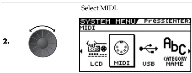
-
- THE MIDI MENU screen appears.
4.

Select PROGRAM MAP.

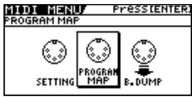
5.

The PROGRAM MAP screen appears.
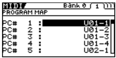
MEMO
The Program Change Map settings are disabled when Map Select is set to "Fix."
| 6. | Select the received Program number. | MEMO ·Use the cursor buttons (left and right) to select the Bank Select number. ·When using only Program Change messages to make program changes, without using Bank Select messages, set the Program number (1-128) when the Bank Select number is “0.” |
| 7. | Set the corresponding patch number of the received Program number. | |
| 8. | Repeat Step 6-7 as needed, setting patch numbers to their corresponding Program numbers, until the Program Change Map is completed. |
Changing Patches Using Bank Select Messages
A bank select message consists of a set of two control change messages, the controllers numbered 0 (CC#0) and 32 (CC#32). Normally, you select a sound by using the bank select message followed by a program change message. On the GT-10, these messages are used for changing patch numbers.
Changing Patch Numbers on an External MIDI Device from the GT-10
When a patch is selected on the GT-10, the bank select and program change messages sent from the GT-10 correspond with each other as shown below.
| Bank | Number | |||||||
| 1 | 2 | 3 | 4 | |||||
| U01 | 0,0: | 1 | 0,0: | 2 | 0,0: | 3 | 0,0: | 4 |
| U02 | 0,0: | 5 | 0,0: | 6 | 0,0: | 7 | 0,0: | 8 |
| U03 | 0,0: | 9 | 0,0: | 10 | 0,0: | 11 | 0,0: | 12 |
| U04 | 0,0: | 13 | 0,0: | 14 | 0,0: | 15 | 0,0: | 16 |
| U05 | 0,0: | 17 | 0,0: | 18 | 0,0: | 19 | 0,0: | 20 |
| U06 | 0,0: | 21 | 0,0: | 22 | 0,0: | 23 | 0,0: | 24 |
| U07 | 0,0: | 25 | 0,0: | 26 | 0,0: | 27 | 0,0: | 28 |
| U08 | 0,0: | 29 | 0,0: | 30 | 0,0: | 31 | 0,0: | 32 |
| U09 | 0,0: | 33 | 0,0: | 34 | 0,0: | 35 | 0,0: | 36 |
| U10 | 0,0: | 37 | 0,0: | 38 | 0,0: | 39 | 0,0: | 40 |
| U11 | 0,0: | 41 | 0,0: | 42 | 0,0: | 43 | 0,0: | 44 |
| U12 | 0,0: | 45 | 0,0: | 46 | 0,0: | 47 | 0,0: | 48 |
| U13 | 0,0: | 49 | 0,0: | 50 | 0,0: | 51 | 0,0: | 52 |
| U14 | 0,0: | 53 | 0,0: | 54 | 0,0: | 55 | 0,0: | 56 |
| U15 | 0,0: | 57 | 0,0: | 58 | 0,0: | 59 | 0,0: | 60 |
| U16 | 0,0: | 61 | 0,0: | 62 | 0,0: | 63 | 0,0: | 64 |
| U17 | 0,0: | 65 | 0,0: | 66 | 0,0: | 67 | 0,0: | 68 |
| U18 | 0,0: | 69 | 0,0: | 70 | 0,0: | 71 | 0,0: | 72 |
| U19 | 0,0: | 73 | 0,0: | 74 | 0,0: | 75 | 0,0: | 76 |
| U20 | 0,0: | 77 | 0,0: | 78 | 0,0: | 79 | 0,0: | 80 |
| U21 | 0,0: | 81 | 0,0: | 82 | 0,0: | 83 | 0,0: | 84 |
| U22 | 0,0: | 85 | 0,0: | 86 | 0,0: | 87 | 0,0: | 88 |
| U23 | 0,0: | 89 | 0,0: | 90 | 0,0: | 91 | 0,0: | 92 |
| U24 | 0,0: | 93 | 0,0: | 94 | 0,0: | 95 | 0,0: | 96 |
| U25 | 0,0: | 97 | 0,0: | 98 | 0,0: | 99 | 0,0: | 100 |
| U26 | 1,0: | 1 | 1,0: | 2 | 1,0: | 3 | 1,0: | 4 |
| U27 | 1,0: | 5 | 1,0: | 6 | 1,0: | 7 | 1,0: | 8 |
| U28 | 1,0: | 9 | 1,0: | 10 | 1,0: | 11 | 1,0: | 12 |
| U29 | 1,0: | 13 | 1,0: | 14 | 1,0: | 15 | 1,0: | 16 |
| U30 | 1,0: | 17 | 1,0: | 18 | 1,0: | 19 | 1,0: | 20 |
| U31 | 1,0: | 21 | 1,0: | 22 | 1,0: | 23 | 1,0: | 24 |
| U32 | 1,0: | 25 | 1,0: | 26 | 1,0: | 27 | 1,0: | 28 |
| U33 | 1,0: | 29 | 1,0: | 30 | 1,0: | 31 | 1,0: | 32 |
| U34 | 1,0: | 33 | 1,0: | 34 | 1,0: | 35 | 1,0: | 36 |
| U35 | 1,0: | 37 | 1,0: | 38 | 1,0: | 39 | 1,0: | 40 |
If you wish to know whether the receiving device can recognize bank select messages or not, refer to the description for control changes in the MIDI implementation chart provided in the owner's manual of the receiving device.
If the receiving device does not recognize bank select messages, it will ignore the bank select messages and recognize only the program change messages.
Changing Patch Numbers on the GT-10 from an External MIDI Device
When the MIDI Map Select parameter set to Fix, to change patch numbers on the GT-10 using bank select messages sent from an external MIDI device, check how the external bank select and program change messages correspond with the patch numbers on the GT-10.
Corresponding Table with the Patch Numbers when the MIDI Map Select is Fix
CC#0: Controller Number 0 (Bank Select MSB)
- CC#0 data of a value of 04H or higher, and the CC#32 are ignored.
(Example) When changing to Patch #30-3 (Bank U30, Number 3)
Transmit MIDI messages from an external MIDI sequencer in following order.
CC#0: 1
PC#: 19
Transmitting Data to an External MIDI Device (Bulk Dump)
With the GT-10, you can use Exclusive messages to set another GT-10 to the same settings or to save effect sound settings to MIDI sequencers and other such devices. This transmission of data is referred to as bulk dump.
Making the Connections
| When Saving to a MIDI Sequencer | When Transmitting Data to Another GT-10 |
| Connect as shown in the figure below, and put the sequencer in the state where it is ready to receive Exclusive messages. | Connect as shown in the figure below, and match the Device ID for the transmitting and receiving devices. |
| MIDI IN MIDI OUT | MIDI IN MIDI OUT |
| For instructions on operating the sequencer, refer to the owner's manual for the sequencer you are using. |
Transmitting
| 1. | SYSTEM | The SYSTEM MENU screen appears. | |
| 2. | Select MIDI. | ||
| SYSTEM MENU PressiENTER | |||
| MIDI | |||
| LCD MIDI USB ABC (CATEGORY NAME) | |||
| 3. | CATEGORY/ENTER | The MIDI MENU screen appears. | |
| 4. | Select B.DUMP. | ||
| BULK DUMP | |||
| SYSTEM PROGRAM MAP B.DUMP | |||
| 5. | CATEGORY/ENTER | The BULK DUMP screen appears. | |
| MIDIF | |||
| BULK DUMP | |||
| SYSTEM Temp ENTER:START | |||
| 6. | Select the start and end of the data to be transmitted. |
The following types of data can be transmitted. You can transmit data by specifying the range from the start to the end of transmission.
| Displayed | Data Transmitted |
| System | System parameter settings |
| Quick | Settings for User Quick Setting |
| U01-1-U50-4 | Settings for Patch Number U01-1 through U50-4 |
| Temp | Settings for the patch that is currently selected |
7.
CATEGORY/
ENTER
The data is transmitted.
Receiving Data from an External MIDI Device (Bulk Load)
You can restore settings by importing data that has been saved on a MIDI sequencer or the like by a bulk dump. This data-receiving operation is called a "bulk load."
Making the Connections
When Receiving Data Saved on a MIDI Sequencer
Connect as shown below. Set the GT-10's Device ID to the same number that was used when the data was transmitted to the MIDI sequencer (p. 81).
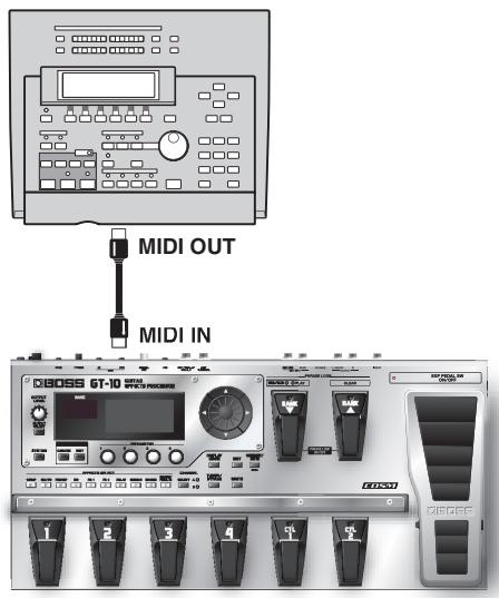
MEMO
For instructions on operating the sequencer, refer to the owner's manual for the sequencer you are using.
Receiving
- Transmit the data from the external MIDI device.
MEMO
- When data is being received, the message "BULK DATA RECEIVING..." appears on the display.
- Keep the power on while the bulk data is being received.
- If the message "MIDI BUFFER FULL" appears, check the connections and reduce the tempo of the transmitting MIDI device.
Chapter 7 Using the GT-10 Connected to a Computer Via USB
Before Connecting with USB
With the GT-10, you can use USB to transmit both digital audio signals between the GT-10 and your computer.
Installing and Setting the USB Driver
Just by connecting the GT-10 to your PC/Mac with a USB cable, audio signal can be transferred bidirectionally via USB. The GT-10 uses a standard driver that is found on OS. The driver will be installed automatically once connected with your computer via USB.
And using the specialized driver, you can record, play back, and edit audio with high-quality sound and stable timing. It also allows you to control the GT-10 using MIDI messages via USB.
You can download the special GT-10 driver from the Roland local website.
The program and procedures for installing the driver vary according to the operating environment; carefully read the Readme included in the downloaded file.
What is a USB Driver?
A USB driver is software that acts as a go-between in transferring data between computer applications (such as recording software and sequencer software) and the USB device when the computer and USB device are connected using a USB cable. The USB driver transmits data from the applications to the USB device, and conversely, passes messages from the USB device to the applications.
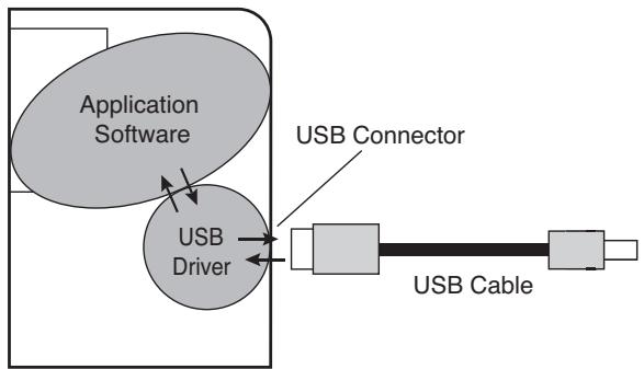
Computer
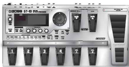
GT-10
Exchanging MIDI Messages between the Computer and the GT-10
If you set the GT-10 into the specialized driver mode (p. 91) and connect it to your PC/Mac by a USB cable, you can transfer MIDI message bidirectionally via USB.
Set your computer MIDI input and output ports to "GT-10."
If you set USB connection between the GT-10 and PC/Mac, MIDI message transfer via MIDI connectors become inactivated.

For more on MIDI-related settings, refer to "Making the Settings for MIDI Functions" (p. 80).
Switching the Driver Mode
Switches two operational modes, one which uses the special driver contained on the downloaded file, and one in which the OS's (Windows/Mac OS) standard driver is used.
- Quit all sequencer software and other applications on the computer that are using the GT-10.
SYSTEM The SYSTEM MENU screen appears.
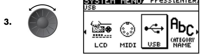
The USB screen appears.
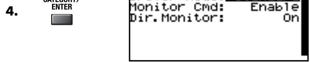

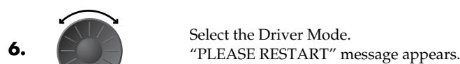
| Setting | Explanation |
| Standard | This mode uses the OS's standard USB driver. |
| MEMO You cannot use MIDI when Standard is selected as the driver mode. If you want to use MIDI with the USB connection, set the GT-10 to the advanced driver mode. | |
| Advanced | This mode uses the special driver. |
| MEMO If you have not yet installed the special driver for the Advanced mode, turn off the power to the GT-10 in this condition and install the driver. |
- Turn the GT-10's power off and then back on again.
MEMO
The functions of a mode won't become available until after the power has been turned off, then on again.
Setting the USB Functions
The following section describes the GT-10's USB-related functions.
Make these settings in accordance with how you plan to use the GT-10.
Setting the Digital Audio Signal Input and Output
This lets you adjust the volume level of the digital audio signals output from the GT-10 and adjust the amount of digital audio from USB (computer) to be mixed in.
| 1. | SYSTEM | The SYSTEM MENU screen appears. | |
| 2. | Select INPUT/OUTPUT. | ||
| SYSTEM MENU / PressEnter. INPUT/OUTPUT PATCH SEARCH TUNER | |||
| 3. | CATEGORY/ ENTER | The INPUT/OUTPUT screen appears. | |
| 4. | Select the TOTAL (page 3) screen. | ||
| INPUT/OUTPUT / if 3 TOTAL NS Threshold : 0dB Rev Level : 100% USB/DGT Out Lev : 100% USB Mix Level : 100% Main Out Level : -10dB | |||
| 5. | Move the cursor to USB/DGT Out Lev or USB Mix Level. | ||
| 6. | Adjust the parameters. | ||
| Parameter | Explanation |
| USB/DGT Out Lev | Adjusts the volume level of the digital audio signals output to the USB (Computer) and DIGITAL OUT connectors. |
| USB Mix Level | Sets the volume level of the mixed digital audio signals from USB (Computer) when INPUT SELECT (p. 61) is set to “Guitar 1-3.” |
Setting the Direct Monitor
Switches the output of the GT-10 sound to the OUTPUT and PHONES jacks.
| 1. | SYSTEM | The SYSTEM MENU screen appears. | |
| 2. | Select USB. | ||
| SYSTEM MENU PressEnter USB LCD MIDI USB CATEGORIES NAME | |||
| 3. | CATEGORY/ENTER | The USB screen appears. | |
| Driver Mode: Standard Monitor Cmd: Enable Dir.Monitor: On | |||
| 4. | Move the cursor to Dir.Monitor. | ||
| 5. | Select the Monitor mode. | cf. For more information on signal paths set by the Direct Monitor parameter settings, refer to “Signal Flow” (p. 142). |
| Parameter/Range | Explanation |
| Off | Set this to Off if transmitting audio data internally through a computer (Thru).No sound is heard at this time unless the setting for the computer is Thru. |
| On | The GT-10 sound is output. Set this to On when using the GT-10 as a standalone device, without connecting to a computer (only USB In input sound will be output if this is set to Off). |
| MEMO · This setting cannot be saved. It is set to On when the power is turned on. · If you are using the special driver, you can control Dir.Monitor On/Off from ASIO 2.0-compatible application. | |
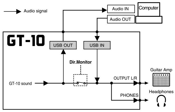
Controlling the Direct Monitor Setting from an External Device
This setting determines whether or not the command (the Direct Monitor command) controlling the Direct Monitor setting (p. 93) is enabled.
| 1. | SYSTEM | The SYSTEM MENU screen appears. | |
| 2. | Select USB. | ||
| SYSTEM MENU Press ENTER USB LCD MIDI USB CATEGORIES NAME | |||
| 3. | The USB screen appears. | ||
| USB Driver Mode: Standard Monitor Cmd: Enable Dir.Monitor: On | |||
| 4. | Move the cursor to Monitor Cmd. | ||
| 5. | Set the desired value. |
| Parameter/Range | Explanation |
| Disable | The Direct Monitor command is disabled, maintaining the Direct Monitor mode set by the GT-10. |
| Enable | The Direct Monitor command is enabled, allowing the Direct Monitor mode to be switched from an external device. |
Recording the GT-10's Output with a Computer
In the computer application, set the audio input port to the GT-10.
MEMO
If passing audio data through the software you're using, switch the direct monitor off.
Applying GT-10 Effects to a Computer's Audio Playback
In the computer application, set the audio output port to the GT-10.
You can use the GT-10 to apply effects to the audio data played by the computer, then record the data again with the computer.
Use this process when, for example, you want to add effects to existing audio data.

Set the software so audio is not passed through it.
| 1. | SYSTEM | The SYSTEM MENU screen appears. | |
| 2. | Select INPUT/OUTPUT. | ||
| SYSTEM MENU PRSSENTER. INPUT/OUTPUT PATCH SEARCH TUNER | |||
| 3. | CATEGORY/ ENTER | The INPUT/OUTPUT screen appears. | |
| 4. | Set the INPUT SELECT parameter to USB In. | MEMO Set the software so audio is not passed through it. | |
| INPUT SELECT USB In INPUT LEVEL PRES 0 dB 0 dB |
| Parameter/Range | Explanation |
| Guitar 1-3 | Effects are applied to the signals input via the INPUT jacks. |
| USB In | Effects are applied to the signals input via USB. |
Chapter 8 Parameters Guide
In this chapter you will find detailed descriptions for each of the GT-10's effects and the parameters used to control them.
MEMO
The format used for parameter names is based on how the names are displayed when the screen is in list view.
The trademarks listed in this document are trademarks of their respective owners, which are separate companies from Roland/BOSS. Those companies are not affiliated with Roland/BOSS and have not licensed or authorized BOSS's GT-10. Their marks are used solely to identify the equipment whose sound is simulated.
COMP (Compressor)
This is an effect that produces a long sustain by evening out the volume level of the input signal. You can switch it to a limiter to suppress only the sound peaks and prevent distortion.
| Parameter/Range | Explanation |
| COMP ON/OFF (Compressor ON/OFF) | |
| Off, On | Turns the COMP effect on/off.Pressing [COMP] switches On and Off. |
| TYPE | |
| Select the compressor type. | |
| Compressor | The effect will function as a compressor. |
| Limiter | The effect will function as a limiter. |
| Sustain (Type=Compressor) | |
| 0-100 | Adjusts the range (time) over which low-level signals are boosted. Larger values will result in longer sustain. |
| Attack (Type=Compressor) | |
| 0-100 | Adjusts the strength of the picking attack when the strings are played. Higher values result in a sharper attack, creating a more clearly defined sound. |
| Threshold (Type=Limiter) | |
| 0-100 | When the input signal level exceeds this threshold level, limiting will be applied. |
| Release (Type=Limiter) | |
| 0-100 | Adjusts the time from when the signal level drops below the threshold until when limiting is removed. |
| Tone | |
| -50-+50 | Adjusts the tone. |
| Level | |
| 0-100 | Adjusts the volume. |
OD/DS (Overdrive/Distortion)
This effect distorts the sound to create long sustain. It provides 30 types of distortion and custom settings.
| Parameter/Range | Explanation | |
| OD/DS (Overdrive/Distortion ON/OFF) | ||
| Off, On | Turns the OD/DS effect on/off.Pressing [OD/DS] switches On and Off. | |
| Type | ||
| Selects the type of distortion. | ||
| BOOSTER | Mid Boost | This is a booster with unique characteristics in the midrange.Making the connection before the COSM amp produces sound suitable for solos. |
| Clean Boost | This not only functions as a booster, but also produces a clean tone that has punch even when used alone. | |
| Treble Bst | This is a booster that has bright characteristics. | |
| BLUES | Blues OD | This is a crunch sound of the BOSS BD-2.This produces distortion that faithfully reproduces the nuances of picking. |
| Crunch | A lustrous crunch sound with an added element of amp distortion. | |
| Natural OD | This is an overdrive sound that provides distortion with a natural feeling. | |
| OD | OD-1 | This is the sound of the BOSS OD-1.This produces sweet, mild distortion. |
| T-Scream | This models an Ibanez TS-808. | |
| Turbo OD | This is the high-gain overdrive sound of the BOSS OD-2. | |
| Warm OD | This is a warm overdrive. | |
| DIST | Distortion | This gives a basic, traditional distortion sound. |
| Mild DS | This is a distortion sound that provides a mild distortion. | |
| Mid DS | This distortion sound features a boosted midrange. | |
| CLASSIC | RAT | This models a Proco RAT. |
| GUV DS | This models a Marshall GUV' NOR. | |
| DST+ | This models a MXR DISTORTION+. | |
| MODERN | Modern DS | This is the deep distortion sound of a large high-gain amp. |
| Solid DS | This is a distortion sound featuring an edge effect. | |
| Stack | A fat sound with an added element of a stack amp's distortion. | |
| METAL | Loud | This is distortion sound that is ideal for performances of heavy riffs. |
| Metal Zone | This is the sound of the BOSS MT-2. It produces a wide range of metal sounds, from old style to slash metal. | |
| Lead | Produces a distortion sound with both the smoothness of an overdrive along with a deep distortion. | |
| FUZZ | '60s FUZZ | This models a FUZZFACE. It produces a fat fuzz sound. |
| Oct FUZZ | This models an ACETONE FUZZ. | |
| MUFF FUZZ | This models an Electro-Harmonix Big Muff π. | |
| Custom | Custom OD/DS You can customize it however you like to match the sound you want. | |
| Drive | ||
| 0-120 | Adjusts the depth of distortion. | |
| Bottom | ||
| -50-+50 | Adjusts the tone for the low frequency range. Turning this to the left (counter-clockwise) produces a sound with the low end cut; turning it to the right boosts the low end in the sound. | |
| Tone | ||
| -50-+50 | Adjusts the tone. | |
| Solo Sw | ||
| Off, On | The tone to one suitable for solos. | |
| SoloLevel | ||
| 0-100 | Adjusts the volume level when the Solo Sw is ON. | |
| EffectLev (Effect Level) | ||
| 0-100 | Adjusts the volume of the OD/DS sound. | |
| DirectLev (Direct Level) | ||
| 0-100 | Adjusts the volume of the direct sound. | |
| Parameter/Range | Explanation |
| CUSTOM TYPE SETTING MEMO Setting available when TYPE is set to Custom. | |
| Type | |
| This selects the basic sound when the TYPE parameter is set to Custom. | |
| OD-1 | This is the sound of the BOSS OD-1. |
| OD-2 | This is a overdrive sound with high gain. |
| CRUNCH | This is a crunch sound. |
| DS-1 | This gives a basic, traditional distortion sound. |
| DS-2 | This creates a heavier distortion sound. |
| METAL-1 | This is a metal sound with a characteristic midrange. |
| METAL-2 | This gives a heavy metal sound. |
| FUZZ | This gives a basic, traditional fuzz sound. |
| Bottom | |
| -50→+50 | This controls the input sound's low-frequency range and adjusts the amount of distortion in the low-frequency range. |
| Top | |
| -50→+50 | This controls the input sound's high-frequency range and adjusts the amount of distortion in the high-frequency range. |
| Low | |
| -50→+50 | Adjusts the low-range tones after distortion is applied. |
| High | |
| -50→+50 | Adjusts the high-range tones after distortion is applied. |
PREAMP
COSM technology simulates different preamp characteristics, speaker sizes, and cabinet shapes.
MEMO
You can make separate settings for Channel A and Channel B.
| Parameter/Range | Explanation |
| PREAMP ON/OFF | |
| Off, On | Turns the COSM AMP effect on/off. Pressing [PREAMP] switches On and Off. |
| Ch.Mode (Channel Mode) | |
| Selects how the two channels are to be used. | |
| Single | Only the channel selected with Channel Select is used. |
| Dual Mono | The output of Channels A and B is mixed. |
| Dynamic | Channels A and B are switched according to the guitar input volume level. This produces dynamic tonal changes in response to the picking dynamics. |
| Ch.Select (Channel Select) | |
| Ch.A, Ch.B | Selects the preamp channel whose settings are to be changed. |
| Ch.DlyTim (Channel Delay Time) | |
| 0ms-100ms | The output from Channel B is slightly delayed. Adjusting this increases the sense of depth and breadth in the sound. |
| This parameter is enabled when Channel mode is set to Dual Mono or Dual L/R. | |
| Dyna.Sens (Dynamic Sensitivity) | |
| 0-100 | Adjusting the sensitivity in response to the input level changes the timing of the channel switches. |
| MEMO This parameter is enabled when Channel mode is set to Dynamic. | |
Preamp Type List
| Parameter/Range | Explanation | |
| Type | ||
| This sets the type of the guitar preamp. | ||
| JC CLEAN | BOSS Clean | This is a clean sound that is smooth and warm. |
| JC-120 | This is the sound of the Roland JC-120. | |
| Jazz Combo | This is a sound suited to jazz. | |
| Full Range | This is a sound with flat response. Good for acoustic guitar | |
| TW CLEAN | Clean TWIN | This models a Fender Twin Reverb. |
| Pro Crunch | This models a Fender Pro Reverb. | |
| Tweed | This models a Fender Bassman 4 x 10" Combo. | |
| DELUX Crnch | This models a Fender Deluxe Reverb. | |
| CRUNCH | BOSS Crunch | This is a crunch sound that can faithfully reproduce the nuances of picking. |
| Blues | This is a sound suited to blues. | |
| Wild Crunch | This is a crunch sound with wild distortion. | |
| StackCrunch | This is a crunch sound with high gain. | |
| COMBO | VO Drive | This models the drive sound of a VOX AC-30TB. This is a sound that it suited to sixties-style British rock. |
| VO Lead | This models the lead sound of the VOX AC-30TB. | |
| VO Clean | This models the clean sound of the VOX AC-30TB. | |
| MATCH | MATCH Drive | This models the sound input to left input on a Matchless D/C-30. A simulation of the latest tube amp widely used in styles from blues and rock. |
| Fat MATCH | This models the sound of a Matchless with a modified high gain. | |
| MATCH Lead | This models the sound input to right input on a Matchless D/C-30. | |
| BG LEAD | BG Lead | This models the lead sound of the MESA/ Boogie combo amp. The sound of a tube amp typical of the late '70s to '80s. |
| BG Drive | This models a MESA/ Boogie with TRE-BLE SHIFT SW on. | |
| BG Rhythm | This models the rhythm channel of a MESA/ Boogie. | |
| MS CLASSIC | MS1959 I | This models the sound input to Input I on a Marshall 1959. This is a trebly sound suited to hard rock. |
| MS1959 I+II | The sound of connecting inputs I and II of the guitar amp in parallel, creating a sound with a stronger low end than I. | |
| MS MODERN | MS HiGain | This models the sound of a Marshall with a modified midrange boost. |
| MS Scoop | This is a Marshall sound that's been tweaked for metal sound. | |
| R-FIER | R-FIER Vnt | Models the sound of the Channel 2 VIN-TAGE Mode on the MESA/Boogie DUAL Rectifier. |
| R-FIER Mdn | Models the sound of the Channel 2 MOD-ERN Mode on the MESA/Boogie DUAL Rectifier. | |
| R-FIER Cln | Models the sound of the Channel 1 CLEAN Mode on the MESA/Boogie DUAL Rectifier. | |
| T-AMP | T-AMP Lead | This models a Hughes & Kettner Triamp AMP3. |
| T-AMP Crnch | This models a Hughes & Kettner Triamp AMP2. | |
| T-AMP Clean | This models a Hughes & Kettner Triamp AMP1. | |
| HI-GAIN | BOSS Drive | This is a drive sound producing awesome distortion. |
| SLDN | This models a Soldano SLO-100. This is the typical sound of the eighties. | |
| Lead Stack | This is a lead sound with high gain. | |
| Heavy Lead | A powerful lead sound featuring extreme distortion. | |
| METAL | BOSS Metal | This is a metal sound suited to heavy riffs. |
| 5150 Drive | This models the lead channel of a Peavey EVH 5150. | |
| Metal Lead | This is a lead sound suited to metal. | |
| Edge Lead | This is a sharp sound suited for lead play. | |
| Custom | This is a custom preamp. You can customize it however you like to match the sound you want. | |
| Through | This switches off the preamp for the chan-nel selected using Ch.Select. | |
JC CLEAN/TW CLEAN/CRUNCH/ COMBO/BG LEAD/MS STACK/R-FIER/ T-AMP/HI-GAIN/METAL
| Parameter/Range | Explanation |
| Gain | |
| 0-120 | Adjusts the distortion of the amp. |
| Bass | |
| 0-100 | Adjusts the tone for the low frequency range. |
| Middle | |
| 0-100 | Adjusts the tone for the middle frequency range. |
| Treble | |
| 0-100 | Adjusts the tone for the high frequency range. |
| Presence | |
| 0-100 | Adjusts the tone for the ultra high frequency range. MEMO You set the Type parameter to VO Drive, VO Lead, VO Clean, MATCH Drive, Fat MATCH or MATCH Lead when the Presence parameter is functioning as the high cut filter. |
| Level | |
| 0-100 | Adjusts the volume of the entire preamp. * Be careful not to raise the Level setting too high. |
| Bright | |
| Turns the bright setting on/off. MEMO The BRIGHT parameter setting is only partially available with some JC CLEAN, TW CLEAN, CRUNCH, or BG LEAD settings in Preamp Type. | |
| Off | Bright is not used. |
| On | Bright is switched on to create a lighter and crispier tone. |
| Gain Sw | |
| Low, Middle, High | Provides for selection from three levels of distortion: LOW, MIDDLE, and HIGH. Distortion will successively increase for settings of LOW, MIDDLE and HIGH. * The sound of each Type is created on the basis that the Gain is set to MIDDLE. So, normally set it to MIDDLE. |
| Solo Sw | |
| Off, On | Solo Sw is switched on to create the tone to one suitable for solos. |
| SoloLevel | |
| 0-100 | Adjusts the volume level when the Solo Sw is ON. |
| SP Type (Speaker Type) | |
| Select the speaker type. | |
| Off | This turns off the speaker simulator. |
| Original | This is the built-in speaker of the amp you selected with PREAMP TYPE. |
| 1x8" | This is a compact open-back speaker cab- inet with one 8-inch speaker. |
| 1x10" | This is a compact open-back speaker cab- inet with one 10-inch speaker. |
| 1x12" | This is a compact open-back speaker cab- inet with one 12-inch speaker. |
| 2x12" | This is a general open-back speaker cab- net with two 12-inch speakers. |
| 4x10" | This is an optimal speaker cabinet for a large enclosed amp with four 10-inch speakers. |
| 4x12" | This is an optimal speaker cabinet for a large enclosed amp with four 12-inch speakers. |
| 8x12" | This is a double stack of two cabinets, each with four 12-inch speakers. |
| Custom | Custom speaker You can customize it however you like to match the sound you want. |
| Mic Type | |
| This setting selects the simulated mic type. | |
| DYN57 | This is the sound of the SHURE SM-57. General dynamic mic used for instru- ments and vocals. Optimal for use in mik- ing guitar amps. |
| DYN421 | This is the sound of the SENNHEISER MD-421. Dynamic mic with extended low end. |
| CND451 | This is the sound of the AKG C451B. Small condenser mic for use with instru- ments. |
| CND87 | This is the sound of the NEUMANN U87. Condenser mic with flat response. |
| FLAT | Simulates a mic with perfectly flat re- sponse. Produces a sonic image close to that of listening to the sound directly from the speakers (on site). |
| Simulates the distance between the mic and speaker. | |
| Off Mic | This setting points the mic away from the speaker. |
| On Mic | Provides conditions whereby the mic is directed more towards the speaker. |
| Mic Pos. (Mic Position) | |
| This simulates the mic position. | |
| Center | Simulates the condition that the mic is set in the middle of the speaker cone. |
| 1–10cm | Simulates the condition that the mic is moved away from the center of the speaker cone. |
| Mic Level | |
| 0-100 | Adjusts the volume of the mic. |
| DirectLev (Direct Level) | |
| 0-100 | Adjusts the volume of the direct sound. |
Custom
| Parameter/Range | Explanation |
| CUSTOM AMP SETTING MEMO Setting available when Type is set to Custom. | |
| Type | |
| Selects the basic type of preamp. | |
| JC Clean | This is the sound of the Roland JC-120. |
| TW Clean | This models a Fender Twin Reverb. |
| Crunch | This is a crunch sound that can produce natural distortion. |
| VO Drive | This models the drive sound of a VOX AC-30TB. |
| BG Lead | This models the lead sound of the MESA/ Boogie combo amp. |
| MS HiGain | This models the sound of a Marshall with a modified midrange boost. |
| Modern Stk | Models the sound of the Channel 2 MOD-ERN Mode on the MESA/Boogie DUAL Rectifier. |
| Bottom | |
| -50-+50 | This controls the input sound's low-frequency range and adjusts the amount of distortion in the low-frequency range. |
| Edge | |
| -50-+50 | This controls the input sound's high-frequency range and adjusts the amount of distortion in the high-frequency range. |
| Bass Freq (Bass Frequency) | |
| -50-+50 | Adjusts the frequency affected by the BASS knob. |
| Tre Freq (Treble Frequency) | |
| -50-+50 | Adjusts the frequency affected by the TREBLE knob. |
| PreampLow | |
| -50-+50 | Adjusts the preamp section's low-frequency tone. |
| Preamp Hi (Preamp High) | |
| -50-+50 | Adjusts the preamp section's high-frequency tone. |
| CUSTOM SPEAKER SETTING MEMO Setting available when SP Type is set to Custom. | |
| SP Size (Speaker Size) | |
| 5"–15" | Selects the size of speaker. |
| Color Low | |
| -10+10 | Adjusts the speaker section's low-frequency tone. |
| ColorHigh | |
| -10+10 | Adjusts the speaker section's high-frequency tone. |
| SP Number (Speaker Number) | |
| x1, x2, x4, x8 | Sets the number of speakers. |
| Cabinet | |
| Selects the speaker cabinet type. | |
| Open | This is an open-backed cabinet. |
| Close | This type of cabinet features an enclosed rear panel. |
EQ (Equalizer)
This adjusts the tone as a equalizer. A parametric type is adopted for the high-middle and low-middle range.
| Parameter/Range | Explanation |
| EQ ON/OFF (Equalizer ON/OFF) | |
| Off, On | Turns the EQ effect on/off. Pressing [EQ] switches On and Off. |
| Low Cut (Low Cut Filter) | |
| Flat, 55Hz–800Hz | This sets the frequency at which the low cut filter begins to take effect. When “Flat” is selected, the low cut filter will have no effect. |
| Low Gain | |
| -20–+20dB | Adjusts the low frequency range tone. |
| Lo-Mid f (Low Middle Frequency) | |
| 20Hz–10.0kHz | Specifies the center of the frequency range that will be adjusted by the Lo-Mid G. |
| Lo-Mid Q (Low Middle Q) | |
| 0.5–16 | Adjusts the width of the area affected by the EQ centered at the LO-Mid f. Higher values will narrow the area. |
| Lo-Mid G (Low Middle Gain) | |
| -20–+20dB | Adjusts the low-middle frequency range tone. |
| Hi-Mid f (High Middle Frequency) | |
| 20Hz–10.0kHz | Specifies the center of the frequency range that will be adjusted by the Hi-Mid G. |
| Hi-Mid Q (High Middle Q) | |
| 0.5–16 | Adjusts the width of the area affected by the EQ centered at the Hi-Mid f. Higher values will narrow the area. |
| Hi-Mid G (High Middle Gain) | |
| -20–+20dB | Adjusts the high-middle frequency range tone. |
| High Gain | |
| -20–+20dB | Adjusts the high frequency range tone. |
| High Cut (High Cut Filter) | |
| 700Hz–11kHz, Flat | This sets the frequency at which the high cut filter begins to take effect. When “Flat” is selected, the high cut filter will have no effect. |
| Level | |
| -20–+20dB | Adjusts the overall volume level of the equalizer. |
FX-1/FX-2
With FX-1 and FX-2, you can select the effect to be used from the following. You can select the same effect for FX-1 and FX-2.
| FX Select | |||
| FX-1/FX-2 Common | T.WAH | Touch Wah | p. 102 |
| AUTO WAH | Auto Wah | p. 103 | |
| SUB WAH | Sub Wah | p. 103 | |
| ADV.COMP | Advanced Compressor | p. 104 | |
| LIMITER | Limiter | p. 104 | |
| GRAPHIC EQ | Graphic Equalizer | p. 104 | |
| PARA EQ | Parametric Equalizer | p. 105 | |
| TONE MODIFY | Tone Modify | p. 105 | |
| GUITAR SIM. | Guitar Simulator | p. 106 | |
| SLOW GEAR | Slow Gear | p. 106 | |
| DEFRETTER | Defretter | p. 106 | |
| WAVE SYNTH | Wave Synth | p. 107 | |
| GUITAR SYNTH | Guitar Synth | p. 107 | |
| SITAR SIM. | Sitar Simulator | p. 108 | |
| OCTAVE | Octave | p. 109 | |
| PITCH SHifter | Pitch Shifter | p. 109 | |
| HARMONIST | Harmonist | p. 110 | |
| AUTO RIFF | Auto Riff | p. 111 | |
| SOUND HOLD | Sound Hold | p. 112 | |
| AC.PROCESSOR | Acoustic Processor | p. 112 | |
| FEEDBACKER | Feedbacker | p. 113 | |
| ANTI-FEEDBACK | Anti Feedback | p. 113 | |
| PHASER | Phaser | p. 114 | |
| FLANGER | Flanger | p. 114 | |
| TREMOLO | Tremolo | p. 115 | |
| ROTARY | Rotary | p. 115 | |
| UNI-V | Uni-V | p. 115 | |
| PAN | Pan | p. 115 | |
| SLICER | Slicer | p. 116 | |
| VIBRATO | Vibrato | p. 116 | |
| RING MOD. | Ring Modulator | p. 117 | |
| HUMANIZER | Humanizer | p. 117 | |
| 2X2 CHORUS | 2x2 Chorus | p. 118 | |
| SUB DELAY | Sub Delay | p. 118 | |
| Parameter/Range | Explanation |
| FX-1, FX-2 ON/OFF (Effect ON/OFF] | |
| Off, On | Turns the FX-1 (FX-2) effect on/off. Pressing [FX-1], [FX-2] switches On and Off. |
| FX Select | |
| see above | Selects the effect to be used. |
T.WAH (Touch Wah)
You can produce a wah effect with the filter changing in response to the guitar level.
| Parameter/Range | Explanation |
| Mode | |
| Selects the wah mode. | |
| LPF | This creates a wah effect over a wide fre- quency range. |
| BPF | This creates a wah effect in a narrow fre- quency range. |
| Polarity | |
| Selects the direction in which the filter will change in response to the input. | |
| Up | The frequency of the filter will rise. |
| Down | The frequency of the filter will fall. |
| Sens (Sensitivity) | |
| 0-100 | Adjusts the sensitivity at which the filter will change in the direction determined by the polarity setting. Higher values will result in a stronger re-sponse. With a setting of 0, the strength of picking will have no effect. |
| Frequency | |
| 0-100 | Adjusts the center frequency of the Wah effect. |
| Peak | |
| Adjusts the way in which the wah effect applies to the area around the center frequency. | |
| 0-100 | Higher values will produce a stronger tone which emphasizes the wah effect more. With a value of 50 a standard wah sound will be produced. |
| EffectLev (Effect Level) | |
| 0-100 | Adjusts the volume of the effect sound. |
| DirectLev (Direct Level) | |
| 0-100 | Adjusts the volume of the direct sound. |
AUTO WAH (Auto Wah)
This changes the filtering over a periodic cycle, providing an automatic wah effect.
| Parameter/Range | Explanation |
| Mode | |
| Selects the wah mode. | |
| LPF | This creates a wah effect over a wide fre-quence range. |
| BPF | This creates a wah effect in a narrow fre-quence range. |
| Frequency | |
| 0-100 | Adjusts the center frequency of the Wah effect. |
| Peak | |
| 0-100 | Adjusts the amount of wah effect applied in the range near the center frequency. Higher values will produce a stronger tone which emphasizes the wah effect more. With a value of 50 a standard wah sound will be produced. |
| Rate | |
| 0-100, BPM -BPM | Adjusts the frequency (speed) of the change. |
| When set to BPM, the value of each parameter will be set accord- ing to the value of the “Master BPM” (p. 122) specified for each patch. This makes it easier to achieve effect sound settings that match the tempo of the song. * If, due to the tempo, the time is longer than the range of allowable settings, it is then synchronized to a period either 1/2 or 1/4 of that time. | |
| Depth | |
| 0-100 | Adjusts the depth of the effect. |
| EffectLev (Effect Level) | |
| 0-100 | Adjusts the volume of the effect sound. |
| DirectLev (Direct Level) | |
| 0-100 | Adjusts the volume of the direct sound. |
SUB WAH
You can control the wah effect in real time by adjusting the EXP Pedal or the expression pedal connected to the EXP PEDAL 2 jack.
| Parameter/ Range | Explanation |
| Type | |
| Selects the type of wah. | |
| CRY WAH | This models the sound of the CRY BABY wah pedal popular in the '70s. |
| VO WAH | This models the sound of the VOX V846. |
| Fat WAH | This is a wah sound featuring a bold tone. |
| Light WAH | This wah has a refined sound with no un- usual characteristics. |
| 7string WAH | This expanded wah features a variable range compatible with seven-string and baritone guitars. |
| Reso WAH | This completely original effect offers en-hancements on the characteristic reso-nances produced by analog synth filters. |
| Pedal Pos (Pedal Position) | |
| 0-100 | Adjusts the position of the wah pedal. MEMO This parameter is used after it's been assigned to an EXP Pedal or similar controller. |
| Pedal Min (Pedal Minimum) | |
| 0-100 | Selects the tone produced when the heel of the EXP Pedal is depressed. |
| Pedal Max (Pedal Maximum) | |
| 0-100 | Selects the tone produced when the toe of the EXP Pedal is depressed. |
| EffectLev (Effect Level) | |
| 0-100 | Adjusts the volume of the effect sound. |
| DirectLev (Direct Level) | |
| 0-100 | Adjusts the volume of the direct sound. |
ADV.COMP
(Advanced Compressor)
This is an effect that produces a long sustain by evening out the volume level of the input signal. You can also use it as a limiter to suppress only the sound peaks and prevent distortion.
| Parameter/Range | Explanation |
| Type | |
| Selects the compressor type. | |
| BOSS Comp | This models a BOSS CS-3. |
| Hi-BAND | This is a compressor that adds an even stronger effect in the high end. |
| Light | This is a compressor with a light effect. |
| D-Comp | This models a MXR DynaComp. |
| ORANGE | This is modeled on the sound of the Dan Armstrong ORANGE SQUEEZER. |
| Fat | When applied heavily, this compressor effect provides a fat tone with a boosted midrange. |
| Mild | When applied heavily, this compressor effect produces a sweet tone with the high end cut. |
| Stereo Comp | This selects a stereo compressor. |
| Sustain | |
| 0-100 | Adjusts the range (time) over which low-level signals are boosted. Larger values will result in longer sustain. |
| Attack | |
| 0-100 | Adjusts the attack time. |
| Tone | |
| -50-+50 | Adjusts the tone. |
| Level | |
| 0-100 | Adjusts the volume. |
LIMITER
The limiter attenuates loud input levels to prevent distortion.
| Parameter/Range | Explanation |
| Type | |
| Selects the limiter type. | |
| BOSS Limitr | This selects a stereo limiter. |
| Rack 160D | This models a dbx 160X. |
| Vtg Rack U | This models a UREI 1178. |
| Attack | |
| 0-100 | Adjusts the attack time. |
| Threshold | |
| 0-100 | Adjust this as appropriate for the input signal from your guitar. When the input signal level exceeds this threshold level, limiting will be applied. |
| Ratio | |
| 1:1-∞:1 | This selects the compression ratio used with signals in excess of the threshold level. |
| Release | |
| 0-100 | Adjusts the release time. |
| Level | |
| 0-100 | Adjusts the volume. |
GRAPHIC EQ (Graphic Equalizer)
This adjusts the tone as a equalizer. You can adjust the sound quality in ten bands.
| Parameter | Range |
| 31Hz | -12-+12dB |
| 62Hz | |
| 125Hz | |
| 250Hz | |
| 500Hz | |
| 1kHz | |
| 2kHz | |
| 4kHz | |
| 8kHz | |
| 16kHz | |
| Level | -12-+12dB |
PARA EQ (Parametric Equalizer)
Adjusts the tonal quality. You can adjust the sound quality in four bands.
| Parameter/Range | Explanation |
| Low Cut (Low Cut Filter) | |
| Flat,55Hz-800Hz | This sets the frequency at which the low cut filter begins to take effect. When “Flat” is selected, the low cut filter will have no effect. |
| Low Gain | |
| -20-+20dB | Adjusts the low frequency range tone. |
| Lo-Mid f (Low Middle Frequency) | |
| 20Hz-10.0kHz | Specify the center of the frequency range that will be adjusted by the “Lo-Mid G.” |
| Lo-Mid Q (Low Middle Q) | |
| 0.5-16 | Adjusts the width of the area affected by the EQ centered at the “Lo-Mid f.” Higher values will narrow the area. |
| Lo-Mid G (Low Middle Gain) | |
| -20-+20dB | Adjusts the low-middle frequency range tone. |
| Hi-Mid f (High Middle Frequency) | |
| 20Hz-10.0kHz | Specify the center of the frequency range that will be adjusted by the “Hi-Mid G.” |
| Hi-Mid Q (High Middle Q) | |
| 0.5-16 | Adjusts the width of the area affected by the EQ centered at the “Hi-Mid f.” Higher values will narrow the area. |
| Hi-Mid G (High Middle Gain) | |
| -20-+20dB | Adjusts the high-middle frequency range tone. |
| High Gain | |
| -20-+20dB | Adjusts the high frequency range tone. |
| High Cut (High Cut Filter) | |
| 700Hz-11kHz, Flat | This sets the frequency at which the high cut filter begins to take effect. When “Flat” is selected, the high cut filter will have no effect. |
| Level | |
| -20-+20dB | Adjusts the volume before the equalizer. |
TONE MODIFY
This changes the tone of the connected guitar.
| Parameter/ Range | Explanation |
| Type | |
| Selects the type of tone modification. | |
| Fat | Fat tone with boosted mid range. |
| Presence | Bright tone with boosted high-mid range. |
| Mild | Mild tone with the high end cut back. |
| Tight | Tone with the low frequencies cut. |
| Enhance | Tone with the high frequencies boosted. |
| Resonator 1, 2, 3 | This produces a tone with greater power and punch by adding resonance in the low-frequency range and midrange. |
| Resonance | |
| 0-100 | This adjusts the strength of the low-end and midrange resonance when Type is set to Resonator 1, 2, or 3. |
| Low | |
| -50-+50 | Adjusts the tone for the low frequency range. |
| High | |
| -50-+50 | Adjusts the tone for the High frequency range |
| Level | |
| 0-100 | Adjusts the volume. |
GUITAR SIM. (Guitar Simulator)
Simulation of the characteristics of particular guitar components such as pickups and different guitar bodies allows you to switch among a number of different guitar types all while using a single guitar.
| Parameter/Range | Explanation |
| Type | |
| Selects the type of the guitar simulator. | |
| ‘S’→‘H’ | Changes from a single-coil pickup tone to a humbucking pickup tone. |
| ‘H’→‘S’ | Changes from a humbucking pickup tone to a single-coil pickup tone. |
| ‘H’→‘HF’ | Changes from a humbucking pickup tone to a single-coil pickup half tone. |
| ‘S’→Hollow | Changes a single-coil pickup tone to a full-acoustic tone with the body reso-nance added. |
| ‘H’→Hollow | Changes a humbucking pickup tone to a full-acoustic tone with the body reso-nance added. |
| ‘S’→AC | Changes a single-coil pickup tone to an acoustic guitar tone. |
| ‘H’→AC | Changes a humbucking pickup tone to an acoustic guitar tone. |
| ‘P’→AC | Changes a piezo pickup tone to an acous-tic guitar tone. |
| Low | |
| -50+50 | Adjusts the tone for the low frequency range. |
| High | |
| -50+50 | Adjusts the tone for the High frequency range |
| Body | |
| 0-100 | Adjusts the way the body sounds when Type is set to ‘S’→Hollow,‘H’→Hollow, ‘S’→AC, ‘H’→AC, or‘P’→AC.The body sound increases as the value is raised; reducing the value produces a tone similar to that from a piezo pickup. |
| Level | |
| 0-100 | Adjusts the volume. |
SLOW GEAR
This produces a volume-swell effect ("violin-like" sound).
| Parameter/ Range | Explanation |
| Sens (Sensitivity) | |
| 0–100 | Adjusts the sensitivity of the slow gear. When it is set to a lower value, the effect of the slow gear can be obtained only with a stronger picking, while no effect is obtained with a weaker picking. When the value is set higher, the effect is obtained even with a weak picking. |
| Rise Time | |
| 0–100 | Adjusts the time needed for the volume to reach its maximum from the moment you begin picking. |
DEFRETTER
This simulates a fretless guitar.
| Parameter/Range | Explanation |
| Tone | |
| -50→+50 | Adjusts the amount of blurring between the notes. |
| Sens (Sensitivity) | |
| 0–100 | This controls the input sensitivity of the defretter. |
| Attack | |
| 0–100 | Adjusts the attack of the picking sound. |
| Depth | |
| 0–100 | This controls the rate of the harmonics. |
| Resonance | |
| 0–100 | Adds a characteristically resonant quality to the sound. |
| EffectLev (Effect Level) | |
| 0–100 | Adjust the volume of the defretter sound. |
| DirectLev (Direct Level) | |
| 0–100 | Adjust the volume of the direct sound. |
WAVE SYNTH
This is a synth sound that processes the guitar input signal.
| Parameter/Range | Explanation |
| Wave | |
| Selects a wave type which the synth sound is based. | |
| Saw | Creates a synth sound with a saw waveform(√). |
| Square | Creates a synth sound with the square waveform(□□). |
| Cutoff (Cutoff Frequency) | |
| 0-100 | Adjusts the frequency where the harmonics contents of the sound are cut off. |
| Resonance | |
| 0-100 | This adjusts the amount of resonance (and the tone coloration) in the synth sound. The higher the value, the more the synth tone coloration is emphasized. |
| FLT.Sens (Filter Sensitivity) | |
| 0-100 | This adjusts the amount of filtering applied in response to the input. |
| FLT.Decay (Filter Decay) | |
| 0-100 | This sets the time needed for the filter to finish its sweep. |
| FLT.Depth (Filter Depth) | |
| 0-100 | Adjusts the depth of the filter. When the value is higher, the filter will change more drastically. |
| Synth Lev (Synth Level) | |
| 0-100 | Adjusts the volume of the synth sound. |
| DirectLev (Direct Level) | |
| 0-100 | Adjusts the volume of the direct sound. |
GUITAR SYNTH
This detects the pitch of an electric guitar and outputs a synthesizer sound.
MEMO
When you use a guitar synthesizer, observe the following points.
- It does not work properly when a chord is played. Be sure to mute all the other strings and play only one note at a time.
- When you are to play the next string while a certain sound is still playing, mute the previous sound and then play the next one with a clear attack.
- If the unit cannot detect the attack, it may not sound correctly.
| Parameter/Range | Explanation |
| Wave | |
| This selects a wave type that is the source of the guitar synthesizer. | |
| Square | The unit detects the pitch and attack information from the input guitar sound, then send the square waveform ( ▽□□) from the internal sound generator. |
| Saw | The unit detects the pitch and attack information from the input guitar sound, then send the saw waveform ( ▽□□) from the internal sound generator. |
| Brass | The unit directly processes the input guitar sound and creates a guitar synthesizer sound. It gives a quick sound rise and send the sound with a sharp edge. |
| Bow | The unit directly processes the input guitar sound and creates a guitar synthesizer sound. It outputs a soft sound without attack. |
| Sens (Sensitivity) | |
| 0-100 | Adjusts the input sensitivity. TIP The response of the internal sound source is better with a higher sensitivity value, but the malfunctions will be increased on the other hand. So, try to set it as high as possible without causing malfunction. |
| Chromatic *1 | |
| Off, On | This switches on or off the chromatic function. When it is on, the pitch change of the synthesizer sound is in semitone steps. This does not respond to pitch changes less than a semitone, such as what might be obtained with bending or vibrato. Thus, this is effectively used for realistically playing musical instruments whose pitch will change in steps greater than a semitone, such as a keyboard. |
| Oct Shift *1 | |
| 0,-1,-2 | This allows you to shift the pitch of the internal sound module in an octave step from the guitar sound. |
| PWM Rate (Pulse Width Modulation Rate) *2 | |
| 0-100 | This gives breadth or fatness to the sound by applying modulation to the waveform (only to Square) in the internal sound module. A higher value will quicken the rate of the modulation. |
| PWM Depth (Pulse Width Modulation Depth) *2 | |
| 0-100 | Adjusts the depth of the PWM. When it is set to “0,” no PWM effect is obtained. |
| Cutoff (Cutoff Frequency) | |
| 0-100 | Adjusts the frequency where the harmonics contents of the sound are cut off. |
| Resonance | |
| 0-100 | Adjusts how much of the harmonics contents around the cutoff frequency should be empha-sized. |
| FLT.Sens (Filter Sensitivity) | |
| 0-100 | Adjusts the sensitivity of the filter. When it is set to a lower value, the filter is affected only with stronger picking. When it is set higher, the filter changes even with weaker picking. When it is set to “0,” the depth of the filter will be the same no matter how the picking strength may be. |
| FLT.Decay (Filter Decay) | |
| 0-100 | This sets the time needed for the filter to finish its sweep. |
| FLT.Depth (Filter Depth) | |
| -100-+100 | Adjusts the depth of the filter. When the value is higher, the filter will change more drastically. The polarity of the filter will be opposite with “+” and “-.” |
| Attack | |
| Decay, 0-100 | Adjusts the time needed for a synthesizer sound to reach its maximum. When it is set to a lower value, the sound will rise quickly. When it is set higher, the sound will rise slowly. When it is set to “Decay,” the sound will rise quickly and turn to a Release status re-gardless of the input of the guitar sound. MEMO When “Brass” or “Bow” is selected for the wave, the attack time will not be quicker from a certain level even if the attack is set to “Decay” or “0.” |
| Release | |
| 0-100 | This determines the time needed for the synthe-sizer sound to reach zero from the moment the input of the guitar sound is completed. MEMO When “Brass” or “Bow” is selected for the wave, the guitar signal itself is processed. That is, the synthesizer sound will go down when the guitar signal goes down no matter how long the release may be set. |
| Velocity | |
| 0-100 | This adjusts the amount of the volume change of the synthesizer sound. When it is set to high, the volume change will be greater depending on the picking strength. When it is set to “0,” no volume change is caused even by changing the picking manner. |
| Parameter/Range | Explanation |
| Hold *1 | |
| Off, On | The hold function can sustain the output of the synthesizer sound. If you turn on the hold while a synthesizer sound is being output, the synthesizer sound will be held until you turn it off. MEMO It is assumed that this parameter will be assigned (p. 126) to the footswitch. |
| Synth Lev (Synth Level) | |
| 0-100 | Adjusts the volume of the synthesizer sound. |
| DirectLev (Direct Level) | |
| 0-100 | Adjusts the volume of the direct sound. |
1 Parameter setting included when Wave is set to "Square" or "Saw."
2 Parameter setting included when Wave is set to "Square."
This simulates the sound of the sitar.
| Parameter/Range | Explanation |
| Tone | |
| -50–+50 | This adjusts the tone. The high end is boosted as the value increases. |
| Sens (Sensitivity) | |
| 0–100 | Adjusts the sensitivity of the sitar. When it is set to a lower value, no effect of the si- tar is obtained with weaker picking, while stron- ger picking produces the effect. When it is set to a higher value, the effect of the sitar can be ob- tained whether the picking is weak or strong. |
| Depth | |
| 0–100 | This adjusts the amount of effect applied. |
| Resonance | |
| 0–100 | This adjusts the undulation of the resonance. |
| Buzz | |
| 0–100 | Adjusts the amount of characteristic buzz pro- duced by the “buzz bridge” when the strings make contact with it. |
| EffectLev (Effect Level) | |
| 0–100 | Adjust the volume of the sitar sound. |
| DirectLev (Direct Level) | |
| 0–100 | Adjust the volume of the direct sound. |
OCTAVE
This adds a note one octave lower, creating a richer sound.
MEMO
Because of the need to analyze the pitch, chords (two or more sounds played simultaneously) cannot be played.
| Parameter/Range | Explanation |
| Range | |
| This selects the register to which the effect is applied. | |
| Range 1 | B1 (corresponds to the sound of an open 7th string) to E6 (corresponds to the 1st string played at the 24th fret) |
| Range 2 | B1 (corresponds to the sound of an open 7th string) to E5 (corresponds to the 1st string played at the 12th fret) |
| Range 3 | B1 (corresponds to the sound of an open 7th string) to E4 (corresponds to the sound of an open 1st string) |
| Range 4 | B1 (corresponds to the sound of an open 7th string) to E3 (corresponds to the 4th string played at the 2nd fret) |
| Oct.Level (Octave Level) | |
| 0-100 | Adjusts the volume of the sound one oc-tave below. |
| DirectLev (Direct Level) | |
| 0-100 | Adjusts the volume of the direct sound. |
PITCH SHIFTER
This effect changes the pitch of the original sound (up or down) within a range of two octaves.
| Parameter/Range | Explanation |
| Voice | |
| Selects the number of voices for the pitch shift sound. | |
| 1-Voice | One-voice pitch-shifted sound output in monaural. |
| 2-Mono | Two-voice pitch-shifted sound (PS1, PS2) output in monaural. |
| 2-Stereo | Two-voice pitch-shifted sound (PS1, PS2) output through left and right channels. |
| PS1/PS2 (Pitch Shift) | |
| Mode *1 | |
| Selection for the pitch shifter mode. | |
| Fast, Medium, Slow | The response is slower in the order of FAST, MEDIUM and SLOW, but the modulation is lessened in the same order. |
| Mono | MONO is used for inputting single notes. MEMO You may be unable to produce the intended effect when playing chords (two or more notes played simultaneously). |
| Pitch *1 | |
| -24+24 | Adjusts the amount of pitch shift (the amount of interval) in semitone steps. |
| Fine *1 | |
| -50+50 | Make fine adjustments to the interval. The amount of the change in the Fine 100 is equivalent to that of the Pitch 1. |
| PreDly (Pre Delay) *1 | |
| 0 ms-300 ms, BPM ↓-BPM ↓ | Adjusts the time from when the direct sound is heard until the pitch shifted sounds are inputted. Normally you can leave this set at 0ms. |
| When set to BPM, the value of each parameter will be set according to the value of the “Master BPM” (p. 122) specified for each patch. This makes it easier to achieve effect sound settings that match the tempo of the song. * If, due to the tempo, the time is longer than the range of allowable settings, it is then synchronized to a period either 1/2 or 1/4 of that time. | |
| Fbk (Feedback) | |
| 0-100 | Adjusts the feedback amount of the pitch shift sound. |
| Level *1 | |
| 0-100 | Adjusts the volume of the pitch shifter |
| DirectLev (Direct Level) | |
| 0-100 | Adjusts the volume of the direct sound. |
*1 With Voice set to 2-Mono or 2-Stereo, you can select two sounds.
HARMONIST
Harmonist is an effect where the amount of shifting is adjusted according to an analysis of the guitar input, allowing you to create harmonics based on diatonic scales.
MEMO
- Because of the need to analyze the pitch, chords (two or more sounds played simultaneously) cannot be played.
- You cannot use the Harmonist effect with audio input via USB.
| Parameter/Range | Explanation |
| Voice | |
| Selects the number of voices for the pitch shift sound. | |
| 1-Voice | One-voice pitch-shifted sound output in monaural. |
| 2-Mono | Two-voice pitch-shifted sound (HR1, HR2) output in monaural. |
| 2-Stereo | Two-voice pitch-shifted sound (HR1, HR2) output through left and right channels. |
| HR1/HR2 *1 | |
| Harm (Harmony) *1 | |
| This determines the pitch of the sound added to the input sound, when you are making a harmony. | |
| -2oct+2oct, User | It allows you to set it by up to 2 octaves higher or lower than the input sound. When the scale is set to USER, this parameter sets the user scale number to be used. |
| PreDI (Pre Delay) *1 | |
| 0ms-300ms, BPM -BPM ↓ | Adjusts the time from when the direct sound is heard until the harmonist sounds are heard. Normally you can leave this set at 0ms. |
| When set to BPM, the value of each parameter will be set according to the value of the "Master BPM" (p. 122) specified for each patch. This makes it easier to achieve effect sound settings that match the tempo of the song. * If, due to the tempo, the time is longer than the range of allowable settings, it is then synchronized to a period either 1/2 or 1/4 of that time. | |
| Fbk (Feedback) | |
| 0-100 | Adjusts the feedback amount of the harmonist sound. |
| Level *1 | |
| 0-100 | Adjusts the volume of the harmony sound. |
| Master Key | |
| C (Am)-B (G#m) | This sets the key for the HARMONIST. |
| Parameter/Range | Explanation |
| The key setting corresponds to the key of the song (#, b) as follows. | |
| Major C F B E A D Minor Am Dm Gm Cm Fm B'm Major G D A E B F# Minor Em Bm F#m C#m G#m D#m | |
| DirectLev (Direct Level) | |
| 0-100 | Adjusts the volume of the direct sound. |
| Parameter | Range |
| UserScale | |
| UserScale 1-12 *2 | |
| C | ▼C-▼C-C-▲C-▲C |
| Dp | ▼Dp-▼Dp-Dp-▲Dp-▲Dp |
| D | ▼D-▼D-D-▲D-▲D |
| Eb | ▼Eb-▼Eb-Eb-▲Eb-▲Eb |
| E | ▼E-▼E-E-▲E-▲E |
| F | ▼F-▼F-F-▲F-▲F |
| F# | ▼F#-▼F#-F#-▲F#-▲F# |
| G | ▼G-▼G-G-▲G-▲G |
| Ab | ▼Ab-▼Ab-Ab-▲Ab-▲Ab |
| A | ▼A-▼A-A-▲A-▲A |
| Bp | ▼Bp-▼Bp-Bp-▲Bp-▲Bp |
| B | ▼B-▼B-B-▲B-▲B |
| Specify the note name of the output sound. The minus (-) and plus (+) symbols indicate sounds above or below the set note name. Triangles next to the note names indicate octaves. One downward-pointing triangle indicates a note one octave below the note displayed; two triangles indicate a two-octave drop. One upward-pointing triangle indicates a note one octave above the note displayed; two triangles indicate a two-octave rise. | |
| Note Detect | |
| Off, On | When this is set to "On," then after the input sound is recognized, the cursor automatically moves to the right (the next sound). Pressing [CATEGORY/ENTER] switches On and Off the Note Detect function. |
1 HR1 and HR2 are set individually.
2 Effective with User selected for Harm parameter.
Creating Harmonist Scales (User Scale)
When HARM is set to any value from -2oct to +2oct, and the harmony does not sound the way you intend, use a User scale. You can set the corresponding pitches to be output for each input pitch.
- Set HR1 (or HR2) to User in the HARMONIST screen.
- Select the screen of the HR1 settings (page 2) or the HR2 settings (page 3) with Cursor [▶].
The User scale setting screen appears.
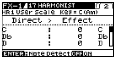
- Use Cursor [▲][▼], dial, to set the amount of pitch shift for each voice.
AUTO RIFF
This allows you to automatically produce a phrase simply by picking a single note. This can be used to easily play extremely rapid phrases.
MEMO
- Because of the need to analyze the pitch, chords (two or more sounds played simultaneously) cannot be played.
- Reception of large amounts of MIDI data while Auto Riff is playing may result in disturbances in the sound.
| Parameter/Range | Explanation |
| Phrase | |
| Preset1-Preset30, User | Select the phrase. User-programmed phrases are used when User is selected. |
| Loop | |
| Off, On | If “Loop” is turned “On,” the phrase will be played back continuously. |
| Tempo | |
| 0-100,BPM o -BPM | Adjusts the speed of the phrase. |
| When set to BPM, the value of each parameter will be set according to the value of the “Master BPM” (p. 122) specified for each patch. This makes it easier to achieve effect sound settings that match the tempo of the song.* If, due to the tempo, the time is longer than the range of allowable settings, it is then synchronized to a period either 1/2 or 1/4 of that time. | |
| Sens (Sensitivity) | |
| 0-100 | Adjust the sensitivity of triggering. With low settings of this parameter, softly picked notes will not retrigger the phrase (i.e., the phrase will continue playing), but strongly picked notes will retrigger the phrase so that it will playback from the beginning. With high settings of this parameter, the phrase will be retriggered even by softly picked notes. No retriggering occurs when the value is set to “0.” |
| MasterKey *1 | |
| C (Am)-B (G#m) | Select the key of the song that you wish to play. |
| Attack | |
| 0-100 | By adding an attack to each note of the phrase you can produce a sensation as though the notes were being picked. |
| Hold | |
| Off, On | If you turn hold “On” after you pick a note, the effect sound will continue even after there is no input signal. |
| EffectLev (Effect Level) | |
| 0-100 | Adjusts the volume of the phrase. |
| DirectLev (Direct Level) | |
| 0-100 | Adjusts the volume of the direct sound. |
Creating Original Phrases (User Phrase)
In addition to the 30 different prepared phrases, you can also create a your own original phrase (User phrases).
- Set the Phrase parameter to the "User."
- Select the screen of page 2 with press Cursor [▶]. The USER PHRASE SETTING screen appears.
| FX-1 18 AUTO RIFF | |||||
| User Phrase Setting | |||||
| In | 1 | 2 | 3 | 4 | 5 |
| C | C | C | C | C | C |
| Db | Db | Db | Db | Db | Db |
| D | D | D | D | D | D |
| ENTER:Note DetectOFFON | |||||
- Press Cursor [▲][▼][▲][▶] to move the cursor, then rotate the dial to set the User phrase.
In:
This makes the phrase setting with respect to the input sound. For instance, when a C is picked, the phrase shown in the C row is played. Phrases of up to 16 notes can be played.
| Parameter | Range |
| C | ▼C-▼C-C-▲C-▲C |
| D, | ▼Db-▼Db-Dp-▲Db-▲Db |
| D | ▼D-▼D-D-▲D-▲D |
| E, | ▼Eb-▼Eb-Eb-▲Eb-▲Eb |
| E | ▼E-▼E-E-▲E-▲E |
| F | ▼F-▼F-F-▲F-▲F |
| F# | ▼F#-▼F#-F#-▲F#-▲F# |
| G | ▼G-▼G-G-▲G-▲G |
| A, | ▼A#-▼A#-A#-▲A#-▲A# |
| A | ▼A-▼A-A-▲A-▲A |
| B, | ▼B#-▼B#-B#-▲B#-▲B# |
| B | ▼B-▼B-B-▲B-▲B |
| Specify the note name of the output sound. The minus (-) and plus (+) symbols indicate sounds above or below the set note name. Triangles next to the note names indicate octaves. One downward-pointing triangle indicates a note one octave below the note displayed; two triangles indicate a two-octave drop. One upward-pointing triangle indicates a note one octave above the note displayed; two triangles indicate a two-octave rise. | |
| --- | Indicates a tie. This carries over the same note from the previous step. |
| End | Determines the last step. The step immediately before the one for which "end" has been set becomes the actual last step. |
| Note Detect | |
| Off, On | When this is set to "On," then after the input sound is recognized, the cursor automatically moves to the right (the next sound). Pressing [CATEGORY/EN-TER] switches On and Off the Note Detect function. |
SOUND HOLD
You can have sound played on the guitar be held continuously. This effect allows you to perform the melody in the upper registers while holding a note in the lower registers.

This function will not work properly when two or more notes are played simultaneously.
| Parameter/Range | Explanation |
| Hold | |
| Off, On | Switches the hold sound on and off. Normally, this is controlled with the CTL 1, 2 pedals or CTL 3/4 jack or the foot-switch connected to the CTL 3,4 jack. |
| Rise Time | |
| 0-100 | Adjusts how rapidly the Sound Hold sound is produced. |
| EffectLev (Effect Level) | |
| 0-120 | Adjusts the volume of the hold sound. |
AC.PROCESSOR (Acoustic Processor)
This processor allows you to change the sound produced by the pickup on an acoustic electric guitar, creating a richer sound similar to that obtained with a microphone placed close to the guitar.
| Parameter/Range | Explanation |
| Type | |
| Selects the modeling type. | |
| Small | This is the sound of a small-bodied acousti c guitar. |
| Medium | This is a standard, unadorned acoustic guitar sound. |
| Bright | This is a bright acoustic guitar sound. |
| Power | This is a powerful acoustic guitar sound. |
| Bass | |
| -50-+50 | Adjusts the low-end balance. |
| Middle | |
| -50-+50 | Adjusts the midrange balance. |
| Middle F (Middle Frequency) | |
| 20.0Hz-10.0kHz | Specifies the frequency range to be adjust- ed with Middle. |
| Treble | |
| -50-+50 | Adjusts the high-end balance. |
| Presence | |
| -50-+50 | Adjusts the balance in the extended up- per range. |
| Level | |
| 0-100 | Adjusts the volume. |
FEEDBACKER
This allows you to use feedback playing techniques.
MEMO
- Note that the notes you want to apply feedback to must be played singly and cleanly.
- You can use the footswitch to switch the effect on and off. For more details, refer to "Switching Effects On and Off with the Pedals" (p. 55).
| Parameter/Range | Explanation |
| Mode | |
| OSC | An artificial feedback sound will be created internally. When OSC is selected, the effect is activated after a single note is played and the note stabilizes. A feedback effect is created when the effect switches on; the feedback disappears when the OSC effect switches off. |
| Natural | Analyzes the pitch of the guitar sound being input, and then creates a feedback sound. |
| Rise Time *1 | |
| 0-100 | This determines the time needed for the volume of the feedback sound to reach its maximum from the moment the effect is turned on. |
| Rise T (▲) (Rise Time (▲))*1 | |
| 0-100 | This determines the time needed for the volume of the one octave higher feedback sound to reach its maximum from the moment the effect is turned on. |
| F.B.Level (Feedback Level) | |
| 0-100 | Adjusts the volume of the feedback sound. |
| F.B.Lv (▲) (Feedback Level (▲))*1 | |
| 0-100 | Adjusts the volume of the one octave higher feedback sound. |
| Vib RATE (Vibrato Rate) *1 | |
| 0-100, BPM -BPM | Adjusts the rate of the vibrato when the feedbacker is on. |
| When set to BPM, the value of each parameter will be set according to the value of the "Master BPM" (p. 122) specified for each patch. This makes it easier to achieve effect sound settings that match the tempo of the song. * If, due to the tempo, the time is longer than the range of allowable settings, it is then synchronized to a period either 1/2 or 1/4 of that time. | |
| Vib.Depth (Vibrato Depth) *1 | |
| 0-100 | Adjusts the depth of the vibrato when the feedbacker is on. |
ANTI-FEEDBACK
This prevents the acoustic feedback that can be produced by the body resonances of a guitar.
| Parameter/Range | Explanation |
| Freq (Frequency) | 1-3 |
| 0-100 | Set the fixed frequency point at which feedback will be cancelled. You can set up three cancellation points. |
| Depth1-3 | |
| 0-100 | Adjusts the degree of the anti-feedback at each of the three cancellation points. |
*1 Setting available with Mode set to OSC.
PHASER
By adding varied-phase portions to the direct sound, the phaser effect gives a whooshing, swirling character to the sound.
| Parameter/Range | Explanation | |
| Type | ||
| Selects the number of stages that the phaser effect will use. | ||
| 4 Stage | This is a four-phase effect. A light phaser effect is obtained. | |
| 8 Stage | This is an eight-phase effect. It is a popu- lar phaser effect. | |
| 12 Stage | This is a twelve-phase effect. A deep phase effect is obtained. | |
| Bi-Phase | This is the phaser with two phase shift cir-cuits connected in series. | |
| Rate | ||
| 0-100,BPM 。-BPM | This sets the rate of the phaser effect. | |
| When set to BPM, the value of each parameter will be set accord- ing to the value of the "Master BPM" (p. 122) specified for each patch. This makes it easier to achieve effect sound settings that match the tempo of the song.* If, due to the tempo, the time is longer than the range of allowable settings, it is then synchronized to a period either 1/2 or 1/4 of that time. | ||
| Depth | ||
| 0-100 | Determines the depth of the phaser effect. | |
| Manual | ||
| 0-100 | Adjusts the center frequency of the phaser effect. | |
| Resonance | ||
| 0-100 | Determines the amount of resonance (feedback). Increasing the value will em- phasize the effect, creating a more unusu-al sound. | |
| Step Rate | ||
| Off, 0-100,BPM 。-BPM | This sets the cycle of the step function that changes the rate and depth.When it is set to a higher value, the change will be finer. Set this to "Off" when not using the Step function. | |
| When set to BPM, the value of each parameter will be set accord- ing to the value of the "Master BPM" (p. 122) specified for each patch. This makes it easier to achieve effect sound settings that match the tempo of the song.* If, due to the tempo, the time is longer than the range of allowable settings, it is then synchronized to a period either 1/2 or 1/4 of that time. | ||
| EffectLev (Effect Level) | ||
| 0-100 | Adjusts the volume of the phaser. | |
| DirectLev (Direct Level) | ||
| 0-100 | Adjusts the volume of the direct sound. | |
FLANGER
The flanging effect gives a twisting, jet-airplane-like character to the sound.
| Parameter/Range | Explanation |
| Rate | |
| 0-100,BPM 。-BPM ∅ | This sets the rate of the flanging effect. |
| When set to BPM, the value of each parameter will be set according to the value of the “Master BPM” (p. 122) specified for each patch. This makes it easier to achieve effect sound settings that match the tempo of the song.* If, due to the tempo, the time is longer than the range of allowable settings, it is then synchronized to a period either 1/2 or 1/4 of that time. | |
| Depth | |
| 0-100 | Determines the depth of the flanging effect. |
| Manual | |
| 0-100 | Adjusts the center frequency at which to apply the effect. |
| Resonance | |
| 0-100 | Determines the amount of resonance (feedback). Increasing the value will emphasize the effect, creating a more unusual sound. |
| Sepration (Separation) | |
| 0-100 | Adjusts the diffusion. The diffusion increases as the value increases. |
| Low Cut (Low Cut Filter) | |
| Flat, 55Hz-800Hz | This sets the frequency at which the low cut filter begins to take effect. When “Flat” is selected, the low cut filter will have no effect. |
| EffectLev (Effect Level) | |
| 0-100 | Adjusts the volume of the flanger. |
| DirectLev (Direct Level) | |
| 0-100 | Adjusts the volume of the direct sound. |
TREMOLO
Tremolo is an effect that creates a cyclic change in volume.
| Parameter/Range | Explanation |
| WaveShape | |
| 0-100 | Adjusts changes in volume level. A high-er value will steepen wave's shape. |
| Rate | |
| 0-100,BPM,-BPM | Adjusts the frequency (speed) of the change. |
| When set to BPM, the value of each parameter will be set accord-ing to the value of the "Master BPM" (p. 122) specified for each patch. This makes it easier to achieve effect sound settings that match the tempo of the song.* If, due to the tempo, the time is longer than the range of allowable settings, it is then synchronized to a period either 1/2 or 1/4 of that time. | |
| Depth | |
| 0-100 | Adjusts the depth of the effect. |
ROTARY
This produces an effect like the sound of a rotary speaker.
| Parameter/Range | Explanation |
| Speed Sel (Speed Select) | |
| Slow, Fast | This parameter changes the simulated speaker's rotating speed (Slow or Fast). |
| Rate-Slow | |
| 0-100,BPM -BPM | This parameter adjusts the Speed Sel of rotation when set to “Slow.” |
| Rate-Fast | |
| 0-100,BPM -BPM | This parameter adjusts the Speed Sel of rotation when set to “Fast.” |
| When the Rate-Slow or Rate-Fast set to BPM, the value of each pa-rameter will be set according to the value of the “Master BPM” (p. 122) specified for each patch. This makes it easier to achieve effect sound settings that match the tempo of the song. * If, due to the tempo, the time is longer than the range of allowable settings, it is then synchronized to a period either 1/2 or 1/4 of that time. | |
| Rise Time | |
| 0-100 | This parameter adjusts the time it takes for the rotation Speed Sel to change when switched from “Slow” to “Fast.” |
| Fall Time | |
| 0-100 | This parameter adjusts the time it takes for the rotation Speed Sel to change when switched from “Fast” to “Slow.” |
| Depth | |
| 0-100 | This parameter adjusts the amount of depth in the rotary effect. |
UNI-V
This models a Uni-Vibe.
Although this resembles a phaser effect, it also provides a unique undulation that you can't get with a regular phaser.
| Parameter/Range | Explanation |
| Rate | |
| 0-100,BPM 。 -BPM ∅ | Adjusts the rate of the Uni-V effect. |
| When set to BPM, the value of each parameter will be set according to the value of the “Master BPM” (p. 122) specified for each patch. This makes it easier to achieve effect sound settings that match the tempo of the song. * If, due to the tempo, the time is longer than the range of allowable settings, it is then synchronized to a period either 1/2 or 1/4 of that time. | |
| Depth | |
| 0-100 | Adjusts the depth of the Uni-V effect. |
| Level | |
| 0-100 | Adjusts the volume. |
PAN
With the volume level of the left and right sides alternately changing, when playing sound in stereo, you can get an effect that makes the guitar sound appear to fly back and forth between the speakers.
| Parameter/Range | Explanation |
| Type | |
| Auto | This varies the volume level on the left and right according to the settings for Wave-Shape, Rate, and Depth. |
| Manual | Output uses the volume balance set with Position. |
| WaveShape *1 | |
| 0-100 | Adjusts changes in volume level. A higher value will steepen wave's shape. |
| Rate *1 | |
| 0-100,BPM 。-BPM | Adjusts the frequency (speed) of the change. |
| When set to BPM, the value of each parameter will be set according to the value of the "Master BPM" (p. 122) specified for each patch. This makes it easier to achieve effect sound settings that match the tempo of the song.* If, due to the tempo, the time is longer than the range of allowable settings, it is then synchronized to a period either 1/2 or 1/4 of that time. | |
| Depth *1 | |
| 0-100 | Adjusts the depth of the effect. |
| Position *2 | |
| L100-CENTER-R100 | This adjusts the volume balance between the left and right channels. |
1 Setting available when Type is set to Auto.
2 Setting available when Type is set to Manual.
SLICER
This consecutively interrupts the sound to create the impression that a rhythm backing phrase is being played.
| Parameter/Range | Explanation |
| Pattern | |
| P1-P20 | Select the slice pattern that will be used to cut the sound. |
| Rate | |
| 0-100,BPM 。-BPM | Adjust the rate at which the sound will be cut. |
| When set to BPM, the value of each parameter will be set according to the value of the "Master BPM" (p. 122) specified for each patch. This makes it easier to achieve effect sound settings that match the tempo of the song.* If, due to the tempo, the time is longer than the range of allowable settings, it is then synchronized to a period either 1/2 or 1/4 of that time. | |
| Trig Sens (Trigger Sensitivity) | |
| 0-100 | Adjust the sensitivity of triggering.With low settings of this parameter, softly picked notes will not retrigger the phrase (i.e., the phrase will continue playing), but strongly picked notes will retrigger the phrase so that it will playback from the beginning. With high settings of this parameter, the phrase will be retriggered even by softly picked notes. |
VIBRATO
This effect creates vibrato by slightly modulating the pitch.
| Parameter/Range | Explanation |
| Rate | |
| 0-100, BPM -BPM | Adjusts the rate of the vibrato. |
| When set to BPM, the value of each parameter will be set according to the value of the "Master BPM" (p. 122) specified for each patch. This makes it easier to achieve effect sound settings that match the tempo of the song. * If, due to the tempo, the time is longer than the range of allowable settings, it is then synchronized to a period either 1/2 or 1/4 of that time. | |
| Depth | |
| 0-100 | Adjusts the depth of the vibrato. |
| Trigger | |
| Off, On | This selects on/off of the vibrato. MEMO It is assumed that this parameter will be assigned (p. 50) to the footswitch. |
| Rise Time | |
| 0-100 | This sets the time passing from the moment the Trigger is turned on until the set vibrato is obtained. MEMO When a patch with Trigger set to On is called up, the effect obtained is identical to what happens when Trigger is switched from Off to On. If you want the vibrato effect to be produced immediately after the patches are switched, set Rise Time to 0. |
RING MOD. (Ring Modulator)
This creates a bell-like sound by ring-modulating the guitar sound with the signal from the internal oscillator. The sound can be unmusical and lack distinctive pitches.
| Parameter/Range | Explanation |
| Mode | |
| This selects the mode for the ring modulator. | |
| Normal | This is a normal ring modulator. |
| Intelligent | By ring-modulating the input signal, a bell like sound is created. The intelligent ring modulator changes the oscillation frequency according to the pitch of the in-put sound and therefore produces a sound with the sense of pitch, which is quite different from Normal. This effect does not give a satisfactory result if the pitch of the guitar sound is not correctly detected. So, you must use single notes, not chords. |
| Frequency | |
| 0–100 | Adjusts the frequency of the internal oscillator. |
| EffectLev (Effect Level) | |
| 0–100 | Adjusts the volume of the effect sound. |
| DirectLev (Direct Level) | |
| 0–100 | Adjusts the volume of the direct sound. |
HUMANIZER
This can create human vowel-like sounds.
| Parameter/Range | Explanation |
| Mode | |
| This sets the mode that switches the vowels. | |
| Picking | It changes from vowel 1 to vowel 2 along with the picking. The time spent for the change is adjusted with the rate. |
| Auto | By adjusting the rate and depth, two vowels (Vowel 1 and Vowel 2) can be switched automatically. |
| Random | Five vowels (A, E, I, O, U) are called out at random by adjusting the rate and depth. |
| Vowel 1 *1 | |
| a, e, i, o, u | Selects the first vowel. |
| Vowel 2 *1 | |
| a, e, i, o, u | Selects the second vowel. |
| Sens (Sensitivity) *2 | |
| 0-100 | Adjusts the sensitivity of the humanizer. When it is set to a lower value, no effect of the humanizer is obtained with weaker picking, while stronger picking produces the effect. When it is set to a higher value, the effect of the humanizer can be obtained wheth-er the picking is weak or strong. |
| Rate | |
| 0-100,BPM o -BPM | Adjusts the cycle for changing the two vowels. |
| When set to BPM, the value of each parameter will be set accord- ing to the value of the "Master BPM" (p. 122) specified for each patch. This makes it easier to achieve effect sound settings that match the tempo of the song.* If, due to the tempo, the time is longer than the range of allowable settings, it is then synchronized to a period either 1/2 or 1/4 of that time. | |
| Depth | |
| 0-100 | Adjusts the depth of the effect. |
| Manual *3 | |
| 0-100 | This determines the point where the two vowels are switched. When it is set to 50, vowel 1 and vowel 2 are switched in the same length of time. When it is set to low- er than 50, the time for vowel 1 is shorter. When it is set to higher than 50, the time for vowel 1 is longer. |
| Level | |
| 0-100 | Adjusts the volume. |
1 Setting available with Mode set to Picking or Auto.
2 Setting available with Mode set to Picking.
*3 Setting available with Mode set to Auto.
2X2 CHORUS
Frequency band division is employed to produce two different choruses, one for low frequencies and one for higher frequencies, for both the left and right channels (for a total of four). This allows you to achieve a more natural chorus sound.
| Parameter/Range | Explanation | |
| Xover f (Crossover Frequency) | ||
| 100Hz-4.00kHz | This sets the frequency dividing the low-and high-frequency ranges. | |
| Lo Rate (Low Rate) | ||
| 0-100,BPM 。 -BPM 》 | Adjust the speed of the chorus effect for the low frequency range. | |
| When set to BPM, the value of each parameter will be set according to the value of the "Master BPM" (p. 122) specified for each patch. This makes it easier to achieve effect sound settings that match the tempo of the song.* If, due to the tempo, the time is longer than the range of allowable settings, it is then synchronized to a period either 1/2 or 1/4 of that time. | ||
| Lo Depth (Low Depth) | ||
| 0-100 | Adjust the depth of the chorus effect for the low frequency range. If you wish to use this as a doubling effect, use a setting of 0. | |
| Lo PreDly (Low Pre Delay) | ||
| 0.0ms-40.0ms | Adjusts the delay of the effect sound in the low-frequency range. Extending the pre-delay will produce the sensation of multiple sounds (doubling ef-fect). | |
| Lo Level (Low Level) | ||
| 0-100 | Adjusts the volume of the effect sound in the low-frequency range. | |
| Hi Rate (High Rate) | ||
| 0-100,BPM 。 -BPM 》 | Adjust the speed of the chorus effect for the high frequency range. | |
| When set to BPM, the value of each parameter will be set according to the value of the "Master BPM" (p. 122) specified for each patch. This makes it easier to achieve effect sound settings that match the tempo of the song.* If, due to the tempo, the time is longer than the range of allowable settings, it is then synchronized to a period either 1/2 or 1/4 of that time. | ||
| Hi Depth (High Depth) | ||
| 0-100 | Adjust the depth of the chorus effect for the high frequency range. If you wish to use this as a doubling effect, use a setting of 0. | |
| Hi PreDly (High Pre Delay) | ||
| 0.0ms-40.0ms | Adjusts the delay of the effect sound in the high-frequency range. Extending the pre-delay will produce the sensation of multiple sounds (doubling ef-fect). | |
| Hi Level (High Level) | ||
| 0-100 | Adjusts the volume of the effect sound in the high-frequency range. | |
SUB DELAY
This is a delay with the maximum delay time of 1,000ms . This effect is useful for making the sound fatter.
| Parameter/Range | Explanation |
| Dly Time (Delay Time) | |
| 1ms-1000ms, BPM ↓-BPM ↓ | Adjusts the delay time. |
| When set to BPM, the value of each parameter will be set according to the value of the "Master BPM" (p. 122) specified for each patch. This makes it easier to achieve effect sound settings that match the tempo of the song. * If, due to the tempo, the time is longer than the range of allowable settings, it is then synchronized to a period either 1/2 or 1/4 of that time. * If you tap [CATEGORY/ENTER], the delay time will change to match the timing of your tapping. | |
| Feedback | |
| 0-100 | Adjusts the volume that is returned to the input. Higher settings will result in more delay repeats. |
| Hi-Cut (High Cut Filter) | |
| 700Hz-11kHz, Flat | This sets the frequency at which the high cut filter begins to take effect. When "Flat" is selected, the high cut filter will have no effect. |
| EffectLev (Effect Level) | |
| 0-120 | Adjusts the volume of the delay sound. |
| DirectLev (Direct Level) | |
| 0-100 | Adjusts the volume of the direct sound. |
DELAY
This effect adds delayed sound to the direct sound, giving more body to the sound or creating special effects.
| Parameter/Range | Explanation |
| DELAY ON/OFF | |
| Off, On | Turns the DELAY Effect on/off.Pressing [DELAY] switches On and Off. |
| Type | |
| This selects which type of delay. MEMO ·If you switch patches with the Type set to either Dual-S, Dual-P, or Dual-L/R and then begin to play immediately after the patches change, you may be unable to attain the intended effect in the first portion of what you perform. ·The stereo effect is cancelled if a monaural effect or COSM amp is connected after a stereo delay effect.* | |
| Single | This is a simple monaural delay. |
| Pan | This delay is specifically for stereo output. This allows you to obtain the tap delay effect that divides the delay time, then deliver them to L and R channels. Tap Time OUTPUT L EffectLev DELAY Dly Time OUTPUT R Feedback |
| Stereo | The direct sound is output from the left channel, and the effect sound is output from the right channel. |
| Dual-S(Dual Series) | This is a delay comprising two different delays connected in series. Each delay time can be set in a range from 1 ms to 1700 ms. D1:Delay1 D2:Delay2 |
| Dual-P(Dual Parallel) | This is a delay comprising two delays connected in parallel. Each delay time can be set in a range from 1 ms to 1700 ms. D1 D2 |
| Dual-L/R | This is a delay with individual settings available for the left and right channels. Delay 1 goes to the left channel, Delay 2 to the right. D1 D2 R |
| Reverse | This produces an effect where the sound is played back in reverse. |
| Analog | This gives a mild analog delay sound. The delay time can be set within the range of 1 to 3400 ms |
| Tape | This setting provides the characteristic wavering sound of the tape echo. The delay time can be set within the range of 1 to 3400 ms. |
| Parameter/Range | Explanation |
| Warp | This simultaneously controls the delay sound's feedback level and volume to produce a totally unreal delay. INPUT Level Dep DELAY OUTPUT F.B. Depth Rise Time |
| Modulate | This delay adds a pleasant wavering effect to the sound. |
DELAY Common Parameters
| Parameter/Range | Explanation |
| Dly Time (Delay Time) | |
| 1ms-3400ms, BPM -BPM | This determines the delay time. |
| When set to BPM, the value of each parameter will be set according to the value of the "Master BPM" (p. 122) specified for each patch. This makes it easier to achieve effect sound settings that match the tempo of the song.* If, due to the tempo, the time is longer than the range of allowable settings, it is then synchronized to a period either 1/2 or 1/4 of that time.* If you tap [CATEGORY/ENTER], the delay time will change to match the timing of your tapping. | |
| Feedback | |
| 0-100 | This sets the amount of delay sound returned to the input.A higher value will increase the number of the delay repeats. |
| TERMFeedback is returning a delay signal to the input. | |
| High Cut (High Cut Filter) | |
| 700Hz-11kHz, Flat | This sets the frequency at which the high cut filter begins to take effect. When "Flat" is selected, the high cut filter will have no effect. |
| EffectLev (Effect Level) | |
| 0-120 | Adjusts the volume of the delay sound. |
| DirectLev (Direct Level) | |
| 0-100 | Adjusts the volume of the direct sound. |
Pan
| Parameter/Range | Explanation |
| Tap Time | |
| 0-100% | Adjusts the delay time of the left channel delay. This setting adjusts the L channel delay time relative to the R channel delay time (considered as 100%). |
Dual-S, Dual-P, Dual-L/R
| Parameter/Range | Explanation |
| D1:Time (Delay 1 Time)D2:Time (Delay 2 Time) | |
| 1ms-1700ms,BPM -BPM 。 | This determines the delay time. |
| When set to BPM, the value of each parameter will be set accord-ing to the value of the "Master BPM" (p. 122) specified for each patch. This makes it easier to achieve effect sound settings that match the tempo of the song.When setting to BPM, press [CATEGORY/ENTER] to display the MASTER BPM screen.If no operation if performed within a set period of time, the dis-play returns to the Delay screen.* If, due to the tempo, the time is longer than the range of allowable settings, it is then synchronized to a period either 1/2 or 1/4 of that time.* After setting D1:Time or D2:Time to a value from 1 ms to 1,700 ms,you can press [CATEGORY/ENTER] to set the value for D1:Time or D2:Time to a value from 1 ms to 1,700 ms according to the interval you press the button.When Type is set to Dual-S or Dual-P, D1:Time is not changed. | |
| D1:Fbk (Delay 1 Feedback)D2:Fbk (Delay 2 Feedback) | |
| 0-100 | Adjusts the amount of feedback of the Delay 1 (or Delay 2). A higher value will increase the number of the delay repeats. |
| D1:HiCut (Delay 1 High Cut Filter)D2:HiCut (Delay 2 High Cut Filter) | |
| 700Hz-11kHz, Flat | This sets the frequency at which the high cut filter begins to take effect. When "Flat" is selected, the high cut filter will have no effect. |
| D1:Level (Delay 1 Level)D2:Level (Delay 2 Level) | |
| 0-120 | Adjusts the volume of the Delay1 (or Delay 2). |
Warp
| Parameter/Range | Explanation |
| Warp Sw | |
| Off, On | Turns the WARP effect on/off. MEMO This parameter is assigned to the CTL1, CTL2 or CTL 3/4 jack. |
| Rise Time | |
| 0-100 | Adjusts how rapidly the warped delay sound rises. |
| F.B.Depth (Feedback Depth) | |
| 0-100 | Adjusts the feedback level of the warped delay sound. |
| Level Dep (Level Depth) | |
| 0-100 | Adjusts the volume of the warped delay sound. |
Modulate
| Parameter/Range | Explanation |
| Mod.Rate (Modulate Rate) | |
| 0-100 | Adjusts the modulation rate of the delay sound. |
| Mod.Depth (Modulate Depth) | |
| 0-100 | Adjusts the modulation depth of the delay sound. |
CHORUS
In this effect, a slightly detuned sound is added to the original sound to add depth and breadth.
| Parameter/Range | Explanation |
| CHORUS ON/OFF | |
| Off, On | Turns the CHORUS effect on/off. Pressing [CHORUS] switches On and Off. |
| Mode | |
| Selection for the chorus mode. | |
| Mono | This chorus effect outputs the same sound from both L channel and R channel. |
| Stereo1 | This is a stereo chorus effect that adds different chorus sounds to L channel and R channel. |
| Stereo2 | This stereo chorus uses spatial synthesis, with the direct sound output in the L channel and the effect sound output in the R channel. |
| Rate | |
| 0-100, BPM -BPM | Adjusts the rate of the chorus effect. |
| When set to BPM, the value of each parameter will be set according to the value of the "Master BPM" (p. 122) specified for each patch. This makes it easier to achieve effect sound settings that match the tempo of the song. * If, due to the tempo, the time is longer than the range of allowable settings, it is then synchronized to a period either 1/2 or 1/4 of that time. | |
| Depth | |
| 0-100 | Adjusts the depth of the chorus effect. TIP To use it for doubling effect, set the value to 0. |
| Pre Delay | |
| 0.0ms-40.0ms | Adjusts the time needed for the effect sound to be output after the direct sound has been output. By setting a longer pre delay time, you can obtain an effect that sounds like more than one sound is being played at the same time (doubling effect). |
| Low Cut (Low Cut Filter) | |
| Flat, 55Hz-800Hz | This sets the frequency at which the low cut filter begins to take effect. When "Flat" is selected, the low cut filter will have no effect. |
| High Cut (High Cut Filter) | |
| 700Hz-11kHz, Flat | This sets the frequency at which the high cut filter begins to take effect. When "Flat" is selected, the high cut filter will have no effect. |
| EffectLev (Effect Level) | |
| 0-100 | Adjusts the volume of the effect sound. |
REVERB
This effect adds reverberation to the sound.
| Parameter/Range | Explanation |
| REVERB ON/OFF | |
| Off, On | Turns the REVERB effect on/off. Pressing [REVERB] switches On and Off. |
| Type | |
| This selects the reverb type. Various different simulations of space are offered. | |
| Ambience | Simulates an ambience mic (off-mic, placed at a distance from the sound source) used in recording and other applications. Rather than emphasizing the reverberation, this re-verb is used to produce a sense of openness and depth. |
| Room | Simulates the reverberation in a small room. Provides warm reverberations. |
| Hall 1 | Simulates the reverberation in a concert hall. Provides clear and spacious reverberations. |
| Hall 2 | Simulates the reverberation in a concert hall. Provides mild reverberations. |
| Plate | Simulates plate reverberation (a reverb unit that uses the vibration of a metallic plate). Provides a metallic sound with a distinct upper range. |
| Spring | This simulates the sound of a guitar amp's built-in spring reverb. |
| Modulate | This reverb adds the wavering sound found in hall reverb to provide an extremely pleas-ant reverb sound. |
| Rev Time (Reverb Time) | |
| 0.1s–10.0s | Adjusts the length (time) of reverberation. |
| Pre Delay | |
| 0ms–500ms | Adjusts the time until the reverb sound ap-pears. |
| Low Cut (Low Cut Filter) | |
| Flat, 55Hz–800Hz | This sets the frequency at which the low cut filter begins to take effect. When “Flat” is se-lected, the low cut filter will have no effect. |
| High Cut (High Cut Filter) | |
| 700Hz–11kHz, Flat | This sets the frequency at which the high cut filter begins to take effect. When “Flat” is se-lected, the high cut filter will have no effect. |
| Density | |
| 0–10 | Adjusts the density of the reverb sound. |
| EffectLev (Effect Level) | |
| 0–100 | Adjusts the volume of the reverb sound. |
| DirectLev (Direct Level) | |
| 0–100 | Adjusts the volume of the direct sound. |
| Sprg.Sens (Spring Sensitivity) | |
| 0–100 | Adjusts the sensitivity of the spring effect. When the value is set higher, the effect is ob-tained even with a weak picking. |
*1 Setting available with Type set to Spring.
MASTER
These settings are applied to the overall sound.
| Parameter/Range | Explanation |
| Patch Level | |
| 0-200 | Adjusts the volume of the patch. |
| Master Low (Master Low EQ Gain) | |
| -12-+12dB | Adjusts the low frequency range tone. |
| Master Mid f (Master Middle EQ Frequency) | |
| 20Hz-10.0kHz | Specify the center of the frequency range that will be adjusted by the "Master Mid G." |
| Master Mid Q (Master Middle EQ Q) | |
| 0.5-16 | Adjusts the width of the area affected by the EQ centered at the Master Mid f. Higher values will narrow the area. |
| Master Mid G (Master Middle EQ Gain) | |
| -12-+12dB | Adjusts the middle frequency range tone. |
| Master High (Master High EQ Gain) | |
| -12-+12dB | Adjusts the high frequency range tone. |
MASTER BPM/KEY
| Parameter/Range | Explanation |
| Master BPM | |
| 40-250 | Adjust the BPM value for each patch. |
| *BPM (beats per minute) indicates the number of quarter note beats that occur each minute.* When you have an external MIDI device connected, the Master BPM synchronizes to the external MIDI device's tempo, making it impossible to set the Master BPM. To enable setting of the Master BPM, set "Sync Clock" (p. 139) to Internal. | |
| Master Key | |
| C (Am)-B (G#m) | This sets the key for the FX HARMONIST and the FX AUTO RIFF. |
| The key setting corresponds to the key of the song (#, b) as follows. | |
| Major C F B B E A D Minor Am Dm Gm Cm Fm B'm | |
| Major G D A E B F# | |
| Minor Em Bm F#m C#m G#m D#m | |
PEDAL FX
SW&PDL FUNCTION

"Setting CTL/EXP Functions Individually in Each Patch (Pedal FX)" (p. 48)
| Parameter/Range | Explanation |
| CTL1 Func (CTL1 Pedal Function)/CTL2 Func (CTL2 Pedal Function)/EXPSwFunc (EXP Pedal Switch Function) | |
| Off | The function is not assign to the pedals. |
| Ch. A/B | Switches between Preamp channel A and B. |
| OD Solo | Switches the OD/DS SOLO on and off. |
| Solo | Switches the Preamp SOLO on and off. |
| A&B Solo | Switches the preamp SOLO, for both channel A and B, on and off. If one of the two channels is off, both will be turned on. |
| Comp | Switches the COMP on and off. |
| OD/DS | Switches the OD/DS on and off. |
| Preamp | Switches the PREAMP/SPEAKER on and off. |
| EQ | Switches the EQ on and off. |
| FX-1 | Switches the FX-1 on and off. |
| FX-2 | Switches the FX-2 on and off. |
| Delay | Switches the DELAY on and off. |
| Chorus | Switches the CHORUS on and off. |
| Reverb | Switches the REVERB on and off. |
| Pedal FX | Switches the Pedal FX on and off. |
| Send/Return | Switches the SEND/RETURN on and off. |
| Amp Ctrl | Switches the Amp Control on and off. |
| Tuner | Switches the TUNER/BYPASS on and off. |
| Manual | Switches the MANUAL MODE on and off. |
| PL | Switches the PHRASE LOOP on and off. |
| PL Rec/Play | Records/plays back the phrase. |
| PL Clear | Cleared the phrase. |
| PL Mute/Ply | Mutes playback of the phrase. |
| BPM Tap | Used for tap input of the Master BPM. |
| Delay Tap | Used for tap input of the delay time. |
| MIDI Start | Controls the Start/Stop of external MIDI devices (such as sequencers). |
| MMC Play | Controls the Play/Stop of external MIDI devices (such as hard disk recorders). |
| Lev +10 | Increases the patch volume level by 10 units. |
| Lev +20 | Increases the patch volume level by 20 units. |
| Lev -10 | Decreases the patch volume level by 10 units. |
| Lev -20 | Decreases the patch volume level by 20 units. |
| Num Inc | Switches to the next higher patch number in the same bank as the currently selected patch. |
| Num Dec | Switches to the next lower patch number in the same bank as the currently selected patch. |
| Bank Inc | Switches to the next higher bank number. |
| Bank Dec | Switches to the next lower bank number. |
| LED Moment *1 | The pedal indicator lights up while you press the pedal, and it goes out when you release the pedal. |
| LED Toggle *1 | The pedal indicator lights up and goes out when alternate each time you press the pedal. |
| PEDAL FX ON/OFF | |
| OFF, ON | Switches the status of function assigned to EXP1. |
| EXP1 Func (EXP Pedal Function) | |
| Off | The function is not assign to the control-ler. |
| Foot Volume | Controls the Foot Volume. |
| Pedal Bend | Controls the Pedal Bend. |
| WAH | Controls the WAH. |
| PB/FV | Controls the Pedal Bend or Foot Volume. |
| WAH/FV | Controls the WAH or Foot Volume. |
*1 This setting value is enabled in CTL1 Func and CTL2 Func.
WAH
You can control the wah effect in real time by adjusting the EXP Pedal or expression pedal connected to the EXP PEDAL 2 jack.

"Setting CTL/EXP Functions Individually in Each Patch (Pedal FX)" (p. 48)
| Parameter/Range | Explanation |
| Type | |
| This selects the wah type. | |
| CRY WAH | This models the sound of the CRY BABY wah pedal popular in the '70s. |
| VO WAH | This models the sound of the VOX V846. |
| Fat WAH | This a wah sound featuring a bold tone. |
| Light WAH | This wah has a refined smooth sound. |
| 7String WAH | This expanded wah features a variable range compatible with seven-string and baritone guitars. |
| Reso WAH | This completely original effect offers enhancements on the characteristic reso-nances produced by analog synth filters. |
| Custom | Custom wahYou can customize it however you like to match the sound you want. |
| Pdl Pos. (Pedal Position) | |
| 0-100 | Adjusts the position of the wah pedal. |
| MEMOThis parameter is used after it's been assigned to an EXP Pedal or similar controller. | |
| Pedal Min (Pedal Minimum) | |
| 0-100 | Selects the tone produced when the heel of the EXP Pedal is depressed. |
| Pedal Max (Pedal Maximum) | |
| 0-100 | Selects the tone produced when the toe of the EXP Pedal is depressed. |
| EffectLev (Effect Level) | |
| 0-100 | Adjusts the volume of the wah sound. |
| DirectLev (Direct Level) | |
| 0-100 | Adjusts the volume of the direct sound. |
| Custom MEMO Setting available when Type is set to Custom. | |
| Type | |
| This selects the basic sound when the TYPE parameter is set to Custom. | |
| CRY WAH | This models the sound of the CRY BABY wah pedal popular in the '70s. |
| VO WAH | This models the sound of the VOX V846. |
| Fat WAH | This a wah sound featuring a bold tone. |
| Light WAH | This wah has a refined smooth sound. |
| 7String WAH | This expanded wah features a variable range compatible with seven-string and baritone guitars. |
| Q | |
| 0-10 | Adjusts the amount of characteristic ef-fect applied to the wah tone. |
| Range Low | |
| 0-10 | Selects the tone produced when the pedal is back. |
| Range High | |
| 0-10 | Selects the tone produced when the pedal is forward. |
| PRESENCE | |
| 0-10 | Adjusts the tonal quality of the wah ef-fect. |
Pedal Bend/PB
This lets you use the pedal to get a pitch bend effect.

Because of the need to analyze the pitch, chords (two or more sounds played simultaneously) cannot be played.
| Parameter/Range | Explanation |
| Pitch Min (Pitch Minimum) | |
| -24+24 | This sets the pitch at the point where the EXP Pedal is fully lifted. |
| Pitch Max (Pitch Maximum) | |
| -24+24 | This sets the pitch at the point where the EXP Pedal is all the way down. |
| Pdl Pos. (Pedal Position) | |
| 0-100 | Adjusts the pedal position for pedal bend. MEMO This parameter is used after it's been assigned to an EXP Pedal or similar controller. |
| EffectLev (Effect Level) | |
| 0-100 | Adjusts the volume of the pitch bend sound. |
| DirectLev (Direct Level) | |
| 0-100 | Adjusts the volume of the direct sound. |
FootVolume/FV
This is a volume control effect.
Normally, this is controlled with the EXP Pedal or the expression pedal connected to the EXP PEDAL 2 jack.
cf.
"Setting CTL/EXP Functions Individually in Each Patch (Pedal FX)" (p. 48)
| Parameter/Range | Explanation |
| Vol. Curve (Volume Curve) | |
| You can select how the actual volume changes relative to the amount the pedal is pressed. | |
| Slow 1, Slow 2, Normal, Fast | Volume When the pedal is fully raised EXP Pedal When the pedal is fully advanced When the pedal is depressed. |
| Vol. Min (Volume Minimum) | |
| 0-100 | Sets the volume when the heel of the EXP Pedal is depressed. |
| Vol. Max (Volume Maximum) | |
| 0-100 | Selects the volume when the toe of the EXP Pedal is depressed. |
| Level | |
| 0-100 | Adjusts the volume. |
NOTE
You may be unable to properly obtain the foot volume effect if "FEEDBACKER" (p. 113) is connected at a point after FV in the Effect Chain (p. 38).
Parameters You Can Set with PDL:CTL/ EXP
The parameter names displayed in Icon View (or at Play screen 4 (p. 24)) are abbreviated. For information on the parameter names displayed in List View, refer to the chart shown below.
| List View | Icon View (at Play screen 4) |
| Off | Off |
| Ch. A/B | A/B |
| OD Solo | ODSolo |
| Solo | Solo |
| A&B Solo | ABSolo |
| Comp | Comp |
| OD/DS | OD/DS |
| Preamp | Preamp |
| EQ | EQ |
| FX-1 | FX-1 |
| FX-2 | FX-2 |
| Delay | Delay |
| Chorus | Chorus |
| Reverb | Reverb |
| Pedal FX | Pdl FX |
| Send/Return | S/R |
| Amp Ctl | AmpCtl |
| Tuner | Tuner |
| Manual | Manual |
| PL | PL |
| PL Rec/Play | PL R/P |
| PL Clear | PL Clr |
| PL Mute/Ply | PL M/P |
| BPM Tap | BPM Tp |
| Delay Tap | Dly Tp |
| MIDI Start | MIDI |
| MMC Play | MMC |
| Lev +10 | Lev+10 |
| Lev +20 | Lev+20 |
| Lev -10 | Lev-10 |
| Lev -20 | Lev-20 |
| Num Inc | NumInc |
| Num Dec | NumDec |
| Bank Inc | BnkInc |
| Bank Dec | BnkDec |
| LED Moment | LED Mo |
| LED Toggle | LED Tg |
ASSIGN 1-8
You can freely assign functions to the GT-10's controllers.
| Parameter/Range | Explanation |
| ASSIGN 1-8 ON/OFF | |
| Off, On | Turns the ASSIGN1-8 on/off. Pressing [MASTER/PEDAL FX] switches On and Off. |
| Target | |
| This selects the parameter to be changed. Refer to “TARGET PARAMETER” (p. 127). | |
| Min (Minimum) | |
| This sets the minimum value for the range in which the parameter can change. The value differs depending on the parameter assigned for TARGET PARAMETER. | |
| Max (Maximum) | |
| This sets the maximum value for the range in which the parameter can change. The value differs depending on the parameter assigned for TARGET PARAMETER. | |
| Source | |
| This selects the controller to which the function is assigned. | |
| EXP1 PEDAL | EXP Pedal (this unit) |
| CTL1 PEDAL | CTL 1 pedal (this unit) |
| CTL2 PEDAL | CTL 2 pedal (this unit) |
| EXP PEDAL SW | EXP Pedal switch (this unit) |
| EXP2 PEDAL | Expression pedal connected to the EXP PED-AL 2/SUB CTL 3,4 jack. |
| CTL3 PEDAL | footswitch connected to the EXP PEDAL 2/SUB CTL 3,4 jack (jack Tip). |
| CTL4 PEDAL | Expression pedal connected to the EXP PED-AL 2/SUB CTL 3,4 jack (jack Ring). |
| INTERNAL PDL | Refer to “Activating the Virtual Expression Pedal at the Start of Operations (Internal Pedal System)” (p. 54) |
| WAVE PEDAL | Refer to “Activating the Virtual Expression Pedal at the Start of Operations (Internal Pedal System)” (p. 54) |
| INPUT LEVEL | This controls the level of the signal from the INPUT jack. Set the sensitivity in response to the level with Assign INPUT SENS. |
| CC#1-#31, CC#64-#95 | Control Change messages from an external MIDI device (1-31, 64-95) |
| Src Mode (Source Mode) | |
| This determines whether the control pedal will function as a momentary type switch (such as the optional FS-5U). | |
| Moment | The normal state is Off (minimum value), with the switch On (maximum value) only while the footswitch is depressed. |
| Toggle | The setting is toggled On (maximum value) or Off (minimum value) with each press of the footswitch. |
| Parameter/Range | Explanation |
| ActRngLo (Active Range Low) ActRngHi (Active Range High) | |
| ActRngLo: 0-126 ActRngHi: 1-127 | You can set the controllable range for target parameters within the source's operational range. Target parameters are controlled within the range set with ActRngLo and ActRngHi. You should normally set ActRngLo to 0 and ActRngHi to 127. |
| Int Trig (Internal Pedal Trigger) | |
| This sets the trigger that activates the internal pedal. *1 | |
| Patch Change | This is activated when a patch is selected. |
| EXP1 PDL-Low | This is actuated when the EXP Pedal is operat-ed at minimum. |
| EXP1 PDL-Mid | This is activated when the EXP Pedal is de-pressed and an intermediate value is passed. |
| EXP1PDL-High | This is actuated when the EXP Pedal is operat-ed at maximum. |
| CTL1 PEDAL, CTL2 PEDAL | This is activated when the CTL 1 or 2 pedal on the GT-10 is depressed. |
| EXP PEDAL SW | This is activated when the EXP Pedal switch on the GT-10 is turned on. |
| EXP2 PEDAL | This is activated when the expression pedal connected to the EXP PEDAL 2/CTL 3,4 jack is depressed. |
| CTL3 PEDAL | This is activated when the footswitch (jack Tip) connected to the EXP PEDAL 2/CTL 3,4 jack is depressed. |
| CTL4 PEDAL | This is activated when the footswitch (jack Ring) connected to the EXP PEDAL 2/CTL 3,4 jack is depressed. |
| CC#1-#31, CC#64-#95 | This is activated when the value of the Control Change messages (CC#01-31, 64-95) from an external MIDI device exceeds the middle val-ue. |
| Int Time (Internal Pedal Time) | |
| 0-100 | This controls the time needed for the assumed EXP Pedal to move from the returned (lifted) position to the depressed (lowered) position. *1 |
| IntCurve (Internal Pedal Curve) | |
| This selects one of the three types that determines how the assumed expression pedal changes. *1 | |
| Linear | Slow Rise Fast Rise |
| WaveRate (Wave Pedal Rate) | |
| 0-100, BPM -BPM | This determines the time spend for one cycle of the assumed EXP Pedal. *2 |
| When set to BPM, the value of each parameter will be set according to the value of the "Master BPM" (p. 122) specified for each patch. This makes it easier to achieve effect sound settings that match the tempo of the song. * If, due to the tempo, the time is longer than the range of allowable settings, it is then synchronized to a period either 1/2 or 1/4 of that time. | |
| Waveform (Wave Pedal Form) | |
| This selects one of the three types that determines how the assumed EXP Pedal should change. *2 | |
| SAW TRIANGLE SIN | |
| INPUT SENS | |
| 0-100 | This adjusts the input sensitivity when INPUT LEVEL is selected for Source. |
1 The Int Trig, Int Time, and IntCurve parameters are enabled when the SOURCE parameter is set to INTERNAL PDL.
2 The WaveRate and Waveform parameters are enabled when the Source parameter is set to WAVE PEDAL.
TARGET PARAMETER
COMP (Compressor)
| Displayed Parameter | (Real Name) |
| On/Off | |
| Type | |
| Sustain | |
| Attack | |
| Threshold | |
| Release | |
| Tone | |
| Level |
OD/DS (Overdrive/Distortion)
| Displayed Parameter | (Real Name) |
| On/Off | |
| Type | |
| Drive | |
| Bottom | |
| Tone | |
| Solo Sw | (Solo Switch) |
| Solo Level | |
| Effect Level | |
| Direct Level |
PREAMP
| Displayed Parameter | (Real Name) | |
| On/Off | ||
| Ch. Mode | (Channel Mode) | |
| Ch. Select | (Channel Select) | |
| Ch. Dly Time | (Channel Delay Time) | |
| Dynamic Sens | (Dynamic Sensitivity) | |
| A/B: | Type | |
| A/B: | Gain | |
| A/B: | Bass | |
| A/B: | Middle | |
| A/B: | Treble | |
| A/B: | Presence | |
| A/B: | Level | |
| A/B: | Bright | |
| A/B: | Gain Sw | (Gain Switch) |
| A/B: | Solo Sw | (Solo Switch) |
| A/B: | Solo Level | |
| A/B: | Speaker Type | |
| A/B: | Mic Type | (Microphone Type) |
| A/B: | Mic Distance | (Microphone Distance) |
| A/B: | Mic Position | (Microphone Position) |
| A/B: | Mic Level | (Microphone Level) |
| A/B: | Direct Level | |
EQ (Equalizer)
| Displayed Parameter | (Real Name) |
| On/Off | |
| Low Cut | |
| Low Gain | |
| Low-Mid Freq | (Low-Middle Frequency) |
| Low-Mid Q | (Low-Middle Q) |
| Low-Mid Gain | (Low-Middle Gain) |
| High-Mid Freq | (High-Middle Frequency) |
| High-Mid Q | (High-Middle) |
| High-Mid Gain | (High-Middle Gain) |
| High Gain | |
| High Cut | |
| Level |
FX1, FX2: (Effects)
| Displayed Parameter | (Real Name) | |
| On/Off | ||
| Select | ||
| TW: (T.WAH) | Mode | |
| Polarity | ||
| Sens | (Sensitivity) | |
| Frequency | ||
| Peak | ||
| Effect Level | ||
| Direct Level | ||
| AW: (AUTO WAH) | Mode | |
| Frequency | ||
| Peak | ||
| Rate | ||
| Depth | ||
| Effect Level | ||
| Direct Level | ||
| SWH: (SUB WAH) | Type | |
| Pdl Position | (Pedal Position) | |
| Pdl Min | (Pedal Minimum) | |
| Pdl Max | (Pedal Maximum) | |
| Effect Level | ||
| Direct Level | ||
| ACS: (ADV COMP) | Type | |
| Sustain | ||
| Attack | ||
| Tone | ||
| Level | ||
| LM: (LIMITER) | Type | |
| Attack | ||
| Threshold | ||
| Ratio | ||
| Release | ||
| Level | ||
| Displayed Parameter | (Real Name) | |
| GEQ:(GRAPHIC EQ) | 31Hz | |
| 62Hz | ||
| 125Hz | ||
| 250Hz | ||
| 500Hz | ||
| 1kHz | ||
| 2kHz | ||
| 4kHz | ||
| 8kHz | ||
| 16kHz | ||
| Level | ||
| PEQ:(PARAMETRIC EQ) | Low Cut | |
| Low Gain | ||
| Low-Mid Freq | (Low-Middle Frequency) | |
| Low-Mid Q | (Low-Middle Q) | |
| Low-Mid Gain | (Low-Middle Gain) | |
| Hi-Mid Freq | (High-Middle Frequency) | |
| Hi-Mid Q | (High-Middle Q) | |
| Hi-Mid Gain | (High-Middle Gain) | |
| High Gain | ||
| High Cut | ||
| Level | ||
| TM:(TONE MODIFY) | Type | |
| Low | ||
| High | ||
| Resonance | ||
| Level | ||
| GS:(GUITAR SIM) | Type | |
| Low | ||
| High | ||
| Body | ||
| Level | ||
| SC:(SLOW GEAR) | Sens | (Sensitivity) |
| RiseTime | ||
| DF:(DEFRETTER) | Tone | |
| Sens | (Sensitivity) | |
| Attack | ||
| Depth | ||
| Resonance | ||
| Effect Level | ||
| Direct Level | ||
| WSY: (WAVE SYNTH) | Wave | |
| Cutoff | ||
| Resonance | ||
| Filter Sens | (Filter Sensitivity) | |
| Filter Decay | ||
| Filter Depth | ||
| Synth Level | ||
| Direct Level | ||
| GSY: (GUITAR SYNTH) | Sens | (Sensitivity) |
| Wave | ||
| Chromatic | ||
| Octave Shift | ||
| PWM Rate | (Pulse Width Modulation Rate) | |
| PWM Depth | (Pulse Width Modulation Depth) | |
| Cutoff | ||
| Resonance | ||
| Filter Sens | (Filter Sensitivity) | |
| Filter Decay | ||
| Filter Depth | ||
| Attack | ||
| Release | ||
| Velocity | ||
| Hold | ||
| Synth Level | ||
| Direct Level | ||
| STR: (SITAR SIM) | Tone | |
| Sens | (Sensitivity) | |
| Depth | ||
| Resonance | ||
| Buzz | ||
| Effect Level | ||
| Direct Level | ||
| OC: (OCTAVE) | Range | |
| Octave Level | ||
| Direct Level | ||
| PS: (PITCH SHIFTER) | Voice | |
| PS1/2 Mode | ||
| PS1/2 Pitch | ||
| PS1/2 Fine | ||
| PS1/2 Pre Dly | (PS1/2 Pre Delay) | |
| PS1 Feedback | ||
| PS1/2 Level | ||
| Direct Level | ||
| HR: (HARMONIST) | Voice | |
| HR1/2 Harmony | ||
| HR1/2 Pre Dly | (HR1/2 Pre Delay) | |
| HR1 Feedback | ||
| HR1/2 Level | ||
| Direct Level | ||
| Displayed Parameter | (Real Name) | |
| AR: (AUTO RIFF) | Phrase | |
| Loop | ||
| Tempo | ||
| Sens | (Sensitivity) | |
| Attack | ||
| Hold | ||
| Effect Level | ||
| Direct Level | ||
| SH: (SOUND HOLD) | Hold | |
| RiseTime | ||
| Effect Level | ||
| AC: (AC.PROCESSOR) | Type | |
| Bass | ||
| Middle | ||
| Middle Freq | (Middle Frequency) | |
| Treble | ||
| Presence | ||
| Level | ||
| FB: (FEEDBACKER) | Mode | |
| Rise Time | ||
| Rise T (▲) | (Rise Time (▲)) | |
| F.B. Level | (Feedback Level) | |
| F.B. Lv (▲) | (Feedback Level (▲)) | |
| Vibrato Rate | ||
| VibratoDepth | ||
| AFB: (UNIT-FEEDBACK) | Frequency 1 | |
| Depth 1 | ||
| Frequency 2 | ||
| Depth 2 | ||
| Frequency 3 | ||
| Depth 3 | ||
| PH: (PHASER) | Type | |
| Rate | ||
| Depth | ||
| Manual | ||
| Resonance | ||
| StepRate | ||
| Effect Level | ||
| Direct Level | ||
| FL: (FLANGER) | Rate | |
| Depth | ||
| Manual | ||
| Resonance | ||
| Separation | ||
| Low Cut | ||
| Effect Level | ||
| Direct Level | ||
| TR: (TREMOLO) | Wave Shape | |
| Rate | ||
| Depth | ||
| RT: (ROTARY) | Speed Select | |
| Rate Slow | ||
| Rate Fast | ||
| Rise Time | ||
| Fall Time | ||
| Depth | ||
| UV: (UNI-V) | Rate | |
| Depth | ||
| Level | ||
| PAN: | Type | |
| Position | ||
| Wave Shape | ||
| Rate | ||
| Depth | ||
| SL: (SLICER) | Pattern | |
| Rate | ||
| Trigger Sens | (Trigger Sensitivity) | |
| VB: (VIBRATO) | Rate | |
| Depth | ||
| Trigger | ||
| RiseTime | ||
| RM: (RING MOD.) | Mode | |
| Frequency | ||
| Effect Level | ||
| Direct Level | ||
| HU: (HUMANIZER) | Mode | |
| Vowel 1 | ||
| Vowel 2 | ||
| Sens | (Sensitivity) | |
| Rate | ||
| Depth | ||
| Manual | ||
| Level | ||
| 2CE: (2x2 CHORUS) | Crossover f | (Crossover Frequency) |
| Low Rate | ||
| Low Depth | ||
| Low Pre Dly | (Low Pre Delay) | |
| Low Level | ||
| High Rate | ||
| High Depth | ||
| High Pre Dly | (High Pre Delay) | |
| High Level | ||
| Displayed Parameter | (Real Name) | |
| SDD:(SUB DELAY) | Delay Time | |
| Feedback | ||
| High Cut | ||
| Effect Level | ||
| Direct Level | ||
DELAY
| Displayed Parameter | (Real Name) | |
| On/Off | ||
| Type | ||
| Delay Time | ||
| Tap Time | ||
| Feedback | ||
| High Cut | ||
| D1/2: | Time | |
| D1/2: | Feedback | |
| D1/2: | High Cut | |
| D1/2: | Level | |
| Warp Sw | (Warp Switch) | |
| WarpRiseTime | ||
| WarpFB Depth | (Warp Feedback Depth) | |
| WarpLevDepth | (Warp Level Depth) | |
| Modul. Rate | (Modulation Rate) | |
| Modul. Depth | (Modulation Depth) | |
| Effect Level | ||
| Direct Level | ||
CHORUS
| Displayed Parameter | (Real Name) |
| On/Off | |
| Mode | |
| Rate | |
| Depth | |
| Pre Delay | |
| Low Cut | |
| High Cut | |
| Effect Level |
REVERB
| Displayed Parameter | (Real Name) |
| On/Off | |
| Type | |
| Reverb Time | |
| Pre Delay | |
| Low Cut | |
| High Cut | |
| Density | |
| Effect Level | |
| Direct Level | |
| Spring Sens | (Spring Sensitivity) |
MASTER
| Displayed Parameter | (Real Name) |
| Patch Level | |
| Master Low | |
| Master Mid f | (Master Middle Frequency) |
| Master Mid Q | (Master Middle Q) |
| Master Mid G | (Master Middle Gain) |
| Master High |
BPM/KEY
| Displayed Parameter | (Real Name) |
| Master BPM | |
| Master Key |
AMP CTL (AMP Control)
| Displayed Parameter | (Real Name) |
| Amp Ctl Sw | (Amp Control Switch) |
PEDAL
| Displayed Parameter | (Real Name) | |
| On/Off | ||
| WAH | Type | |
| Pdl Position | (Pedal Position) | |
| Pedal Min | (Pedal Minimum) | |
| Pedal Max | (Pedal Maximum) | |
| Effect Level | ||
| Direct Level | ||
| PB | Pitch Min | (Pitch Minimum) |
| Pitch Max | (Pitch Maximum) | |
| Pdl Position | (Pedal Position) | |
| Effect Level | ||
| Direct Level | ||
| FV | Volume Curve | |
| Volume Min | (Volume Minimum) | |
| Volume Max | (Volume Maximum) | |
| Level | ||
SEND/RTN (Send/Return)
| Displayed Parameter | (Real Name) |
| On/Off | |
| Mode | |
| Send Level | |
| Return Level |
NS1, NS2 (Noise Suppressor)
| Displayed Parameter | (Real Name) |
| On/Off | |
| Threshold | |
| Release | |
| Detect |
(Others)
| Displayed Parameter | (Real Name) | |
| Tuner Sw | (Tuner Switch) | |
| Manual ModeSw | (Manual Mode Switch) | |
| PH LOOP | On/Off | |
| Rec/Play | ||
| Clear | ||
| Mute/Play | ||
| TAP | BPM Tap | |
| Delay Tap | ||
| MIDI | Start/Stop | |
| MMCPlay/Stop | ||
| PATCH | Level Inc.10 | (Patch Level Increment 10) |
| Level Inc.20 | (Patch Level Increment 20) | |
| Level Dec.10 | (Patch Level Decrement 10) | |
| Level Dec.20 | (Patch Level Decrement 20) | |
| Number Inc. | (Patch Number Increment) | |
| Number Dec. | (Patch Number Decrement) | |
| Bank Inc. | (Patch Bank Increment) | |
| Bank Dec. | (Patch Bank Decrement) | |
SEND/RETURN
This allows you to connect an external effects device to the SEND and RETURN jacks and use it as part of the GT-10's effects.
| Parameter/Range | Explanation |
| SEND/RETURN ON/OFF | |
| Off, On | Switches the SEND/RETURN on/off. Pressing [MASTER/PEDAL FX] switches On and Off. |
| Mode | |
| Switches the SEND/RETURN mode. | |
| Normal | Outputs the input to SEND/RETURN to the SEND jack and the input from the RE-TURN jack to the circuit post-SEND/RE-TURN. Use this when you want to connect an external effects device serially in the GT-10's effects chain. |
| SEND RETURN | |
| Direct Mix | Outputs the input to SEND/RETURN to the SEND jack, mixes the input from the RETURN jack with the input to SEND/RETURN (the direct sound), then outputs this to the circuit post-SEND/RETURN. Use this when you want to mix the GT-10's effects sounds together with the sound with the external effects device applied to it. |
| SEND RETURN | |
| Branch Out | Outputs the input to SEND/RETURN to the SEND jack. The input from the RE-TURN jack is disregarded. For example, using this with the GT-10's reverb and delay immediately ahead of the SEND/RE-TURN allows you to use the SEND jack as a direct out. |
| SEND | |
| Send Lv | |
| 0-200 | Adjusts the volume of the output to the external effects device. |
| Return Lv | |
| 0-200 | Adjusts the volume of the input from the external effects device. |
AMP CONTROL
By connecting your guitar amp's channel switching jack to the GT-10's AMP CONTROL jack, you can then use Amp Control to switch the amp channel.
This combining of the GT-10 and the amp channels allows you to get an even wider variety of distortion sounds.
Since the Amp Control setting is handled as one of the effects parameters saved to each individual patch, it allows you to switch guitar amp channels with each patch.
| Parameter/Range | Explanation | |
| Amp Control | ||
| Off | Guitar Amp (amps channel switching jack) | Short GT-10 (AMP CONTROL jack) |
| On | Guitar Amp (amps channel switching jack) | Open GT-10 (AMP CONTROL jack) |
- To determine how the amp channels are switched when the circuit is open and shorted, refer to the amp owner's manual, or actually confirm the sounds by operating the amp.
- Note that, depending on the circuitry of the channel switching jack in the guitar amp used, the Amp Control function may not operate.
MEMO
- With Amp Control, not only can you switch amp channels, you can also use it to switch the amp's effects on and off, like a footswitch controller.
- You can also switch this parameter using [MASTER/PEDAL FX] in the AMP CONTROL screen.
NS1/NS2 (Noise Suppressor)
This effect reduces the noise and hum picked up by guitar pickups. Since it suppresses the noise in synchronization with the envelope of the guitar sound (the way in which the guitar sound decays over time), it has very little effect on the guitar sound, and does not harm the natural character of the sound.
- Please connect the noise suppressor in the signal path prior to the reverberation type effect. This setup will prevent an natural break of the reverberation type effect.
| Parameter/Range | Explanation |
| NS1, NS2 ON/OFF (Noise Suppressor ON/OFF) | |
| Off, On | Switches the noise suppressor effect on/off. Pressing [MASTER/PEDAL FX] switches On and Off. |
| Threshold | |
| 0–100 | Adjust this parameter as appropriate for the volume of the noise. If the noise level is high, a higher setting is appropriate. If the noise level is low, a lower setting is appropriate. Adjust this value until the decay of the guitar sound is as natural as possible. * High settings for the threshold parameter may result in there being no sound when you play with your guitar volume turned down. |
| Release | |
| 0–100 | Adjusts the time from when the noise suppressor begins to function until the noise level reaches “0.” |
| Detect | |
| This controls the noise suppressor based on the volume level for the point specified in Detect. | |
| Input | Input volume from input jack. |
| NS Input | Noise suppressor input volume. |
| FV Out | Volume after passing through Foot Vol-ume. |
EZ TONE
This feature allows you to make tone settings based on the equipment you are using and the tonal image you want to create.
STEP1: SETTING
| Parameter/Range | Explanation |
| YOUR PICKUP | |
| SINGLE | Single type pickup |
| HUMBUCKER | Humbucking type pickup |
| OUTPUT SELECT | |
| JC-120 | Set this when connecting a Roland JC-120 guitar amp. |
| SMALL AMP | Use this setting when connecting a compact guitar amp. |
| COMBO AMP | Set this when connecting to the guitar in-put for a combo-type guitar amp (com-bining amp and speakers in a single unit) other than a JC-120. * You may find that setting this to JC-120 may produce good results with your guitar amp. |
| STACK AMP | Use this setting when connecting to the guitar input for a stack-type guitar amp (in which the amp and speakers are sepa-rated) |
| JC-120 Return | Set this when connecting to the JC-120's RETURN. |
| COMBO Return | Set this when connecting to the RETURN on another combo-type amp. |
| STACK Return | Set this when connecting to the RETURN on a stack-type amp. Set STACK Return even when using a power amp for the guitar in combination with a speaker cab-inet. |
| LINE/PHONES | Use this setting when using headphones or when recording with the GT-10 con-nected to a multitrack recorder. |
STEP2: TONE
| Parameter/Range | Explanation |
| BASIC TONE | |
| BASIC TONE lets you create sounds easily by choosing settings close to the musical genre and the feel of the song you want to compose. | |
| BLUES | Blues sound |
| Soul Funk | Soul and Funk sound |
| Jazz | Jazz sound |
| LIVERPOOL | British Rock |
| 70's HARD ROCK | The Hard Rock sound popular in the '70s. |
| 80s METAL | The Metal sound popular in the '80s |
| MODERN METAL | Modern Metal sound |
| West Coast | West Coast sound |
| FuzzRock | Fuzz |
| STUDIO | Recording Studio |
| PROGRESSIVE | Progressive |
| SURF ROCK | Surf Rock sound |
| COUNTRY | Country |
| Acoustic | For Acoustic Guitar |
| PUNK POP | Punk Pop |
STEP3: DRIVE
| Parameter/ Range | Explanation |
| SOLO | The distortion to one suitable for solos. |
| BACKING | The distortion to one suitable for backing. |
| SOFT | This produces warm distortion. |
| HARD | This produces sharp distortion. |
STEP4: EFX
| Parameter/Range | Explanation |
| WET | This produces a deep effect. |
| DRY | This produces sound that is close to the original sound. |
| SHRT (Short) | Echo is shortened. |
| LONG | Echo is lengthened. |
SYSTEM
Used for making settings related to the GT-10's operating environment.
TUNER
| Parameter/Range | Explanation |
| PITCH | |
| 435Hz–445Hz | This sets the reference pitch. |
| OUTPUT | |
| Mute | The tuning sound is not output. |
| Bypass | The tuning sound is output. |
INPUT/OUTPUT
| Parameter/Range | Explanation |
| INPUT SELECT | |
| Guitar 1-Guitar 3,USB In | You can store three separate tone config-urations tailored to the guitars you intend to connect (Guitar 1 through 3). Select USB In when you're inputting audio from a computer via USB. |
| INPUT | |
| LEVEL | |
| -20+20dB | Input volume from input jack. |
| PRES. (Presence) | |
| -20+20dB | Adjusts the ultra high frequency range tone. |
| GLOBAL EQ | |
| Low Gain | |
| -20+20dB | Adjusts the low frequency range tone. |
| Mid Gain (Middle Gain) | |
| -20+20dB | Adjusts the middle frequency range tone. |
| Mid Freq (Middle Frequency) | |
| 20.0Hz-10.0kHz | Specifies the center of the frequency range that will be adjusted by the Mid Gain. |
| Mid Q (Middle Q) | |
| 0.5-16 | Adjusts the width of the area affected by the EQ centered at the Mid Freq. Higher values will narrow the area. |
| High Gain | |
| -20+20dB | Adjusts the high frequency range tone. |
| TOTAL | |
| NS Threshold (Noise Suppressor Threshold) | |
| -20→+20dB | This controls the global threshold level for the noise suppressor settings in each patch. This feature is effective when you connect a different guitar or for adjusting for changes in noise levels in the performance venue. It does not affect the settings in each individual patch. MEMO To use the settings contained in the individual patches, set this to 0 dB. |
| Rev Level (Reverb Level) | |
| 0-200% | This controls the global reverb level for the reverb settings in each patch. Adjusting this reverb level is effective for adjusting to the acoustics of the performance space. It does not affect the settings in each individual patch. MEMO To use the settings contained in the individual patches, set this to 100%. |
| USB/DGT Out Lev (USB/Digital Out Level) | |
| 0-200% | Adjusts the volume level of the digital audio signals output to the USB (Computer). |
| USB Mix Level | |
| 0-200% | Sets the volume level of the mixed digital audio signals from USB (Computer) when Input Select is set to “Guitar 1-3.” |
| Main Out Level | |
| This sets the output reference level to match the equipment connected to the OUTPUT jack. | |
| -10dB | Choose this when connected to a guitar amp. |
| +4dB | Choose this when connected to a record-er, mixer, or other line device. |
PHRASE LOOP
| Parameter/Range | Explanation |
| PHRASE LOOP | |
| Off, On | Switches the Phrase Loop function on/off. |
| Mode | |
| Performance | This records the sound after it passes through the effects. This lets you achieve a rich variety of performances by combining different tones. |
| Patch Edit | This records the sound before it passes through the effects, and applies the effects during loop play. This enables you to adjust effects or compare patch tones. |
| Pdl Mode (Pedal Mode) | |
| Off | The BANK pedals are not used for operation of the Phrase Loop feature. These are used as bank switch pedals. TIP Phrase Loop can be controlled by assigning the Phrase Loop feature to any of the CTL 1 through 4 etc. and maintaining the BANK pedals' bank switching function. |
| On | The BANK pedals are used for operation of the Phrase Loop feature. |
| Rec Mode (Recording Mode) | |
| Mono | Phrases are recorded in mono. |
| Stereo | Phrases are recorded in stereo. |
| Play Lev (Play Level) | |
| 0-120 | Sets the phrase playback volume. |
| Clear Pdl (Clear Pedal Function) | |
| Clear Only | When you press [BANK▲] while the Phrase Loop feature is on, the recorded data is cleared and then GT-10 switches to STANDBY mode. |
| Mute/Clear | When you press [BANK▲] while the Phrase Loop feature is on, the performance of the recorded phrase is muted (the recorded data is not erased). If you then press [BANK▲] again while the phrase is muted, the recorded data is cleared and then GT-10 switches to STANDBY mode. TIP Skillful use of muting lets you combine your own performances with prerecorded phrases at the timing you want. |
MANUAL MODE SETTING
| Parameter/Range | Explanation |
| Number Pedal 1-4, BANK▼Pedal, BANK▲Pedal | |
| The Number pedal and the BANK pedal are used for switching specified effects on and off. | |
| Off | The function is not assign to the pedals. |
| Ch.A/B | Switches between Preamp channel A and B. |
| OD Sol | Switches the OD/DS SOLO on and off. |
| Solo | Switches the Preamp SOLO on and off. |
| A&BSol | Switches the preamp SOLO, for both channel A and B, on and off. If one of the two channels is off, both will be turned on. |
| Comp | Switches the COMP on and off. |
| OD/DS | Switches the OD/DS on and off. |
| Preamp | Switches the PREAMP/SPEAKER on and off. |
| EQ | Switches the EQ on and off. |
| FX1 | Switches the FX-1 on and off. |
| FX2 | Switches the FX-2 on and off. |
| Delay | Switches the DELAY on and off. |
| Chorus | Switches the CHORUS on and off. |
| Reverb | Switches the REVERB on and off. |
| PdlFX | Switches the Pedal FX on and off. |
| S/R | Switches the SEND/RETURN on and off. |
| AmpCtrl | Switches the Amp Control on and off. |
| Tuner | Switches the TUNER/BYPASS on and off. |
| PL | Switches the PHRASE LOOP on and off. |
| PL R/P | Records/plays back the phrase. |
| PL Clr | Cleared the phrase. |
| PL M/P | Mutes playback of the phrase. |
| BPMTap | Used for tap input of the Master BPM. |
| DlyTap | Used for tap input of the delay time. |
| MIDI | Controls the Start/Stop of external MIDI devices (such as sequencers). |
| MMCPly | Controls the Play/Stop of external MIDI devices (such as hard disk recorders). |
| Lev+10 | Increases the patch volume level by 10 units. |
| Lev+20 | Increases the patch volume level by 20 units. |
| Lev-10 | Decreases the patch volume level by 10 units. |
| Lev-20 | Decreases the patch volume level by 20 units. |
| NumInc | Switches to the next higher patch number in the same bank as the currently selected patch. |
| NumDec | Switches to the next lower patch number in the same bank as the currently selected patch. |
| BnkInc | Switches to the next higher bank number. |
| BnkDec | Switches to the next lower bank number. |
PLAY OPTION
| Parameter/Range | Explanation |
| Preamp Mode | |
| Patch | The patch preamp setting is used. This alows you to use different preamp settings in each individual patch. |
| System1-3 | The system's preamp setting is used. This applies the same preamp settings to all patches. |
| Patch ChgMode (Patch Change Mode) | |
| This setting determines whether or not the decay of reverb, delay, and similar effects continue when patches are switched on the GT-10. | |
| Fast | Patches are changed normally. The unit switches to the subsequent patch without any carry-over of the decay from the previous patch's reverb or delay. |
| Smooth | The unit switches to the subsequent patch with the decay from the previous patch's reverb or delay continued after the switch is made. MEMO To ensure smooth switching, the patches may be switched with a delay of one tempo beat. |
| Bank Chg Mode | |
| This sets the timing with which the GT-10 switches to the next patch when switching banks with the pedals. | |
| Wait | Although the indication in the display is updated to reflect the change in the bank when a BANK pedal is pressed, the patch will not change until a number pedal has been pressed. |
| Immed | The patch switches instantly when a BANK pedal or any of the number pedals is pressed. |
| BankExtentMin (Bank Extent Minimum) | |
| P01-P50,U01-U50 | Sets the lower limit for the banks. |
| BankExtentMax (Bank Extent Maximum) | |
| P01-P50,U01-U50 | Sets the upper limit for the banks. |
| EXP PdI Hold (Expression Pedal Hold) | |
| This setting determines whether or not the Assign's (p. 50) operational status is carried over to the next patch when patches are switched. | |
| Off | The Assign's operational status is not carried over. (Example) If a patch is switched while the volume is being controlled with an EXP Pedal, the volume of the subsequent patch is set to the value set in that patch. If the EXP Pedal is operated, the volume will change in accord with the pedal's movement. |
| On | The Assign's operational status is carried over. (Example) If a patch is switched while the volume is being controlled with the EXP Pedal, the volume of the subsequent patch will take on the value determined by the current pedal position (angle). If the patch switched to has the EXP Pedal controlling the wah effect, then the volume assumes the value set in the patch, and the patch's wah effect is given the value derived from the current pedal position (angle). |
| Pdl Indicate (Pedal Indicate) | |
| You can have all unlit pedal indicators flash faintly instead. | |
| Off | The Pedal Indicate function is not use. |
| On | All unlit pedal indicators flash. |
| Num Pdl Sw (Number Pedal Switch) | |
| This allows you to call up various features by pressing the pedals with the same numbers as the currently selected patches. | |
| Off | This function is not operational. |
| Tuner | Switches the Tuner on and off. |
| Ch. A/B | Switches between Preamp channel A and B. |
| OD Solo | Switches the OD/DS SOLO on and off. |
| Solo | Switches the Preamp SOLO on and off. |
| AB Solo | Switches the preamp SOLO, for both channel A and B, on and off. |
| Dial Func (Dial Function) | |
| This setting determines whether or not rotating the dial switches the patches. | |
| Pat&Val | The dial is used both for switching patches and changing the value of settings. In addition to switching patches with the pedals, you can also switch them by rotating the dial. |
| Value | The dial is used only for changing the values of settings. |
CONTROLLER
| Parameter/Range | Explanation |
| SYS KNOB SETTING (System Knob Setting) | |
| Knob P1-P4 | COMP:Sustain, COMP:Attack,COMP:Threshold, COMP:Release,COMP:Level, ODDS:Drive, ODDS:ToneODDS:EfectLev, ODDS:Solo Lev,PRE-A(B):Gain, PRE-A(B):LevelPRE-A(B):Bass, PRE-A(B):MidPRE-A(B):Treble, PRE-A(B):PresncePRE-A(B):SoloLev, EQ:Low CutEQ:Low Gain, EQ:Lo-MidGain, EQ:Hi-MidGain, EQ:High GainEQ:High Cut, DELAY:Time, DELAY:Feedback, DELAY:Hi CutDELAY:EfectLev, DELAY:D1(2)TimeDELAY:D1(2)Fbk, DELAY:D1(2)HCutDELAY:D1(2)Lev, CHORUS:RateCHORUS:Depth, CHORUS:PreDlyCHORUS:E.Lev, REVERB:TimeREVERB:Hi Cut, REVERB:E.LevMASTER:Low, MASTER:MidMASTER:High, Patch LevelPDL:Wah E.Lev, PDL:PB E.LevSR:Send Level, SR:Rtn LevelNS1(2):Threshold, NS1(2):ReleaseGLOBAL EQ:Low, GLOBAL EQ:MidGLOBAL EQ:Hi |
| EXP1/2 PEDAL SETTING | |
| Prefernc (Preference) | |
| Patch | The patch pedal setting is used. This al-ows you to use different pedal settings in each individual patch. |
| System | The CONTROLLER screen's pedal set-ting (Function, Min and Max) is used. This applies the same pedal settings to all patches. |
| Function | |
| Off | The function is not assign to the control-ler. |
| Foot Volume | Controls the Foot Volume. |
| Pedal Bend *1 | Controls the Pedal Bend. |
| WAH *1 | Controls the WAH. |
| PB/FV *1 | Controls the Pedal Bend or Foot Volume. |
| WAH/FV *1 | Controls the WAH or Foot Volume. |
| Patch Level | Controls the Patch Level. |
| *1 This parameter is enabled in EXP1 PEDAL SETTING. | |
| Min (Minimum) | |
| 0-100 | This sets the minimum value for the range in which the parameter can change. |
| Max (Maximum) | |
| 0-1000-200 (Function = Patch Level) | This sets the maximum value for the range in which the parameter can change. |
| EXP PEDAL SW SETTING (Expression Pedal Switch Setting)CTL1-4 PEDAL SETTING (CTL1-4 Pedal Setting) | |
| Prefernc (Preference) | |
| Patch | The patch pedal setting is used. This al-ows you to use different pedal settings in each individual patch. |
| System | The CONTROLLER screen's pedal set-ting (Function, Min, Max and Src Mode) is used. This applies the same pedal set-tings to all patches. |
| Function | |
| Off | The function is not assign to the control-ler. |
| Ch. A/B | Switches between Preamp channel A and B. |
| OD Solo Sw | Switches the OD/DS SOLO on and off. |
| Solo Sw | Switches the Preamp SOLO on and off. |
| A&B Solo | Switches the preamp SOLO, for both channel A and B, on and off.If one of the two channels is off, both will be turned on. |
| Comp Sw | Switches the COMP on and off. |
| OD/DS Sw | Switches the OD/DS on and off. |
| Preamp Sw | Switches the PREAMP/SPEAKER on and off. |
| EQ Sw | Switches the EQ on and off. |
| FX-1 Sw | Switches the FX-1 on and off. |
| FX-2 Sw | Switches the FX-2 on and off. |
| Delay Sw | Switches the Delay on and off. |
| Chorus Sw | Switches the Chorus on and off. |
| Reverb Sw | Switches the Reverb on and off. |
| Pedal FX Sw | Switches the Pedal FX on and off. |
| Send/Rtn Sw | Switches the Send&Return on and off. |
| Amp Ctl Sw | Switches the Amp Control on and off. |
| Tuner | Switches the Tuner/Bypass on and off. |
| Manual Sw | Switches the Manual mode on and off. |
| PL Sw | Switches the PHRASE LOOP on and off. |
| PL Rec/Play | The phrase is recorded/played. |
| PL Clear | The phrase is deleted. |
| PL Mute/Ply | Phrase loop play is muted. |
| BPM Tap | Used for tap input of the Master BPM. |
| Delay Tap | Used for tap input of the delay time. |
| MIDI Start | Controls the Start/Stop of external MIDI devices (such as sequencers). |
| MMC Play | Controls the Play/Stop of external MIDI devices (such as hard disk recorders). |
| P.Lev Inc1 | Increases the patch volume level by 10 units. |
| P.Lev Inc2 | Increases the patch volume level by 20 units. |
| P.Lev Dec1 | Decreases the patch volume level by 10 units. |
| P.Lev Dec2 | Decreases the patch volume level by 20 units. |
| Parameter/Range | Explanation |
| P.Num Inc | Switches to the next higher patch number in the same bank as the currently selected patch. |
| P.Num Dec | Switches to the next lower patch number in the same bank as the currently selected patch. |
| P.Bank Inc | Switches to the next higher bank number. |
| P.Bank Dec | Switches to the next lower bank number. |
| Min (Minimum) | |
| Off, On | This sets the value for times when the switch is Off. |
| Max (Maximum) | |
| Off, On | This sets the value for times when the switch is On. |
| Src Mode (Source Mode) | |
| This sets the behavior of the value each time the switch is operation. | |
| Moment | The normal state is Off (minimum value), with the switch On (maximum value) only while the footswitch is depressed. |
| Toggle | The setting is toggled On (maximum value) or Off (minimum value) with each press of the footswitch. |
Display of Parameters You Can Set with SYS KNOB SETTING
The parameter names displayed in the Play screen are abbreviated. For details about the parameter names, refer to the chart shown below.
| Display with SYS KNOB SETTING | Display at Play screen 1 | Display at the bottom of the Play screen |
| COMP:Sustain | COMP SUSTN | CS SUS |
| COMP:Attack | COMP ATACK | CS ATK |
| COMP:Threshold | COMP THRES | CS THR |
| COMP:Release | COMP RELE | CS REL |
| COMP:Level | COMP LEVEL | CS LEV |
| ODDS:Drive | ODDS DRIVE | OD DRV |
| ODDS:Tone | ODDS TONE | OD TNE |
| ODDS:EfectLev | ODDS E LEV | OD ELV |
| ODDS:Solo Lev | ODDS S LEV | OD SLV |
| PRE:A:Gain | PRE-A GAIN | AchGAN |
| PRE:A:Level | PRE-A LEVEL | AchLEV |
| PRE:A:Bass | PRE-A BASS | AchBAS |
| PRE:A:Mid | PRE-A MID | AchMID |
| PRE:A:Treble | PRE-A TREBL | AchTRB |
| PRE:A:Presnce | PRE-A PRES | AchPRS |
| PRE:A:SoloLev | PRE-A S LEV | AchSLV |
| PRE:A:Mic Lev | PRE-A M LEV | AchMLV |
| PRE:B:Gain | PRE-B GAIN | BchGAN |
| PRE:B:Level | PRE-B LEVEL | BchLEV |
| PRE:B:Bass | PRE-B BASS | BchBAS |
| PRE:B:Mid | PRE-B MID | BchMID |
| PRE:B:Treble | PRE-B TREBL | BchTRB |
| PRE:B:Presnce | PRE-B PRES | BchPRS |
| PRE:B:SoloLev | PRE-B S LEV | BchSLV |
| PRE:B:Mic Lev | PRE-B M LEV | BchMLV |
| EQ:Low Cut | EQ L CUT | EQ LC |
| EQ:Low Gain | EQ LOW | EQ LOW |
| EQ:Lo-MidGain | EQ L MID | EQ LMD |
| EQ:Hi-MidGain | EQ H MID | EQ HMD |
| EQ:High Gain | EQ HIGH | EQ HI |
| EQ:High Cut | EQ H CUT | EQ HC |
| DELAY:Time | DELAY TIME | DD TIM |
| DELAY:Feedback | DELAY FBK | DD FBK |
| DELAY:Hi Cut | DELAY H CUT | DD HC |
| DELAY:EftLev | DELAY E LEV | DD ELV |
| DELAY:D1:Time | DELAY D1TIM | D1 TIM |
| DELAY:D1:Fbk | DELAY D1FBK | D1 FBK |
| DELAY:D1:HCut | DELAY D1HC | D1 HC |
| DELAY:D1:Lev | DELAY D1LEV | D1 LEV |
| DELAY:D2:Time | DELAY D2TIM | D2 TIM |
| DELAY:D2:Fbk | DELAY D2FBK | D2 FBK |
| DELAY:D2:HCut | DELAY D2HC | D2 HC |
| DELAY:D2:Lev | DELAY D2LEV | D2 LEV |
| CHORUS:Rate | CHORS RATE | CE RAT |
| CHORUS:Depth | CHORS DEPTH | CE DPT |
| CHORUS:PreDly | CHORS P DLY | CE DLY |
| CHORUS:E. Lev | CHORS E LEV | CE LEV |
| REVERB:Time | REVRB TIME | RV TIM |
| REVERB:Hi Cut | REVRB H CUT | RV HC |
| REVERB:E. Lev | REVRB E LEV | RV ELV |
| MASTER:Low | MST LOW | MT LOW |
| MASTER:Mid | MST MID | MT MID |
| MASTER:High | MST HIGH | MT HI |
| Patch Level | PATCH LEVEL | PAT LV |
| PDL:WAH:E. Lev | PEDA WAH E | WA ELV |
| PDL:PB:E. Lev | PEDAL PB E | PB ELV |
| SR:Send Level | SR S LEV | SR SND |
| SR:Rtn Level | SR R LEV | SR RTN |
| NS1:Threshold | NS1 THRES | N1 THR |
| NS1:Release | NS1 RELE | N1 REL |
| NS2:Threshold | NS2 THRES | N2 THR |
| NS2:Release | NS2 RELE | N2 REL |
| GLOBAL EQ:Low | GBEQ LOW | GB LOW |
| GLOBAL EQ:Mid | GBEQ MID | GB MID |
| GLOBAL EQ:Hi | GBEQ HIGH | GB HI |
LCD
| Parameter/Range | Explanation |
| Contrast | |
| 1-16 | Adjusts the contrast. |
MIDI
| Parameter/Range | Explanation |
| Rx Channel (Receive Channel) | |
| 1-16ch | This sets the MIDI channel used for re-ceiving MIDI messages. |
| Omni Mode | |
| Omni Off, Omni On | When set to “Omni On,” messages are re-ceived on all channels, regardless of the MIDI channel settings. |
| Tx Channel (Transmit Channel) | |
| 1-16ch | This sets the MIDI Transmit channel used for transmitting MIDI messages. |
| Device ID | |
| 1-32 | This sets the Device ID used for transmit-ting and receiving Exclusive messages. |
| Sync Clock | |
| This setting determines the basis used for synchronizing the tim- ing for effect modulation rates and other time-based parameters. NOTE ·When you have an external MIDI device connected, the Master BPM is then synchronized to the external MIDI device's tempo, thus disabling the Master BPM setting. To enable setting of the Master BPM, set to “Internal.” ·When synchronizing performances to the MIDI Clock signal from an external MIDI device, timing problems in the performance may occur due to errors in the MIDI Clock. | |
| Auto | When the MIDI Clock of the external MIDI device is not being received, the performance is synchronized to the tem- po set in MASTER BPM; when the exter- nal MIDI device's MIDI Clock is being received from the USB or MIDI IN con- nector, the performance is synchronized to that. |
| Internal | The performance is synchronized to the tempo set in MASTER BPM. |
| PC Out (Program Change Out) | |
| This setting determines whether or not Program Change messages are output when patches are switched on the GT-10. | |
| Off | Program Change messages are not out- put, even when patches are switched. |
| On | Program Change messages are simulta- neously output when patches are switched. |
| EXP1/EXP Sw/CTL1/CTL2/EXP2/CTL3/CTL4 Out(Transmit Control Change) | |
| This sets the controller number when the controller operation data is output as Control Change messages. | |
| Off, CC#1-CC#31, CC#64-CC#95 | Selects the controller. |
| Map Select | |
| This setting determines whether patches are switched according to the Program Change Map settings, or to the default settings. | |
| Fix | Switches to the patches according to the default settings. |
| Prog | Switches to the patches according to the Program Change Map. |
| PROGRAM MAP | |
| When switching patches using Program Change messages transmitted by an external MIDI device, you can freely set the correspondence between Program Change messages received by the GT-10 and the patches to be switched to in the “PROGRAM MAP.” | |
| Bank 0-3 /PC#1-PC#128 | This sets the patch number (P01-1 through U50-4) for the corresponding Program Change number. |
| BULK DUMP | |
| On the GT-10, you can use Exclusive messages to provide another GT-10 with identical settings, and save effect settings on a MIDI sequencer or other device. | |
| SYSTEM | System Parameters |
| Quick | Settings for User Quick Setting |
| U01-1-U50-4 | Settings for Patch Number U01-1 through U50-4 |
| Temp | Settings for the patch that is currently called up |
USB
| Parameter/Range | Explanation |
| Driver Mode | |
| Standard | This mode uses the OS's standard USB driver. MEMO You cannot use MIDI when Standard is selected as the driver mode. If you want to use MIDI with the USB connection, set the GT-10 to the advanced driver mode. |
| Advanced | This mode uses the special driver. |
| Monitor Cmd (Monitor Command) | |
| Disable | The Direct Monitor command is disabled, maintaining the Direct Monitor mode set by the GT-10. |
| Enable | The Direct Monitor command is enabled, allowing the Direct Monitor mode to be switched from an external device. |
| Dir.Monitor (Direct Monitor) | |
| Off | Set this to Off if transmitting audio data internally through a computer (Thru). No sound is heard at this time unless the setting for the computer is Thru. |
| On | The GT-10 sound is output. Set this to On when using the GT-10 as a standalone device, without connecting to a computer (only USB input sound will be output if this is set to Off). |
| MEMO · This setting cannot be saved. It is set to On when the power is turned on. · If you are using the special driver, you can control Dir.Monitor On/Off from ASIO 2.0-compatible application. | |
OUTPUT SELECT
This selects the type of device to be connected.
| Parameter/Range | Explanation |
| Mode | |
| Patch | This uses the patch's Output Select setting. You can use a different output setting for each individual patch. |
| System | This uses the system's Output Select setting. The same output setting is used for all patches. |
| Select | |
| JC-120 | Set this when connecting a Roland JC-120 guitar amp. |
| SMALL AMP | Use this setting when connecting a compact guitar amp. |
| COMBO AMP | Set this when connecting to the guitar input for a combo-type guitar amp (com-bining amp and speakers in a single unit) other than a JC-120. * You may find that setting this to JC-120 may produce good results with your guitar amp. |
| STACK AMP | Use this setting when connecting to the guitar input for a stack-type guitar amp (in which the amp and speakers are sepa-rated) |
| JC-120 Return | Set this when connecting to the JC-120's RETURN. |
| COMBO Return | Set this when connecting to the RETURN on another combo-type amp. |
| STACK Return | Set this when connecting to the RETURN on a stack-type amp. Set STACK Return even when using a power amp for the guitar in combination with a speaker cab-inet. |
| LINE/PHONES | Use this setting when using headphones or when recording with the GT-10 con-nected to a multitrack recorder. * Use the LINE/PHONES setting if you are using a speaker simulator. MEMO When headphones are connected to the PHONES jack, tonal adjustments are applied so the sound is close to that produced by the guitar amp. |
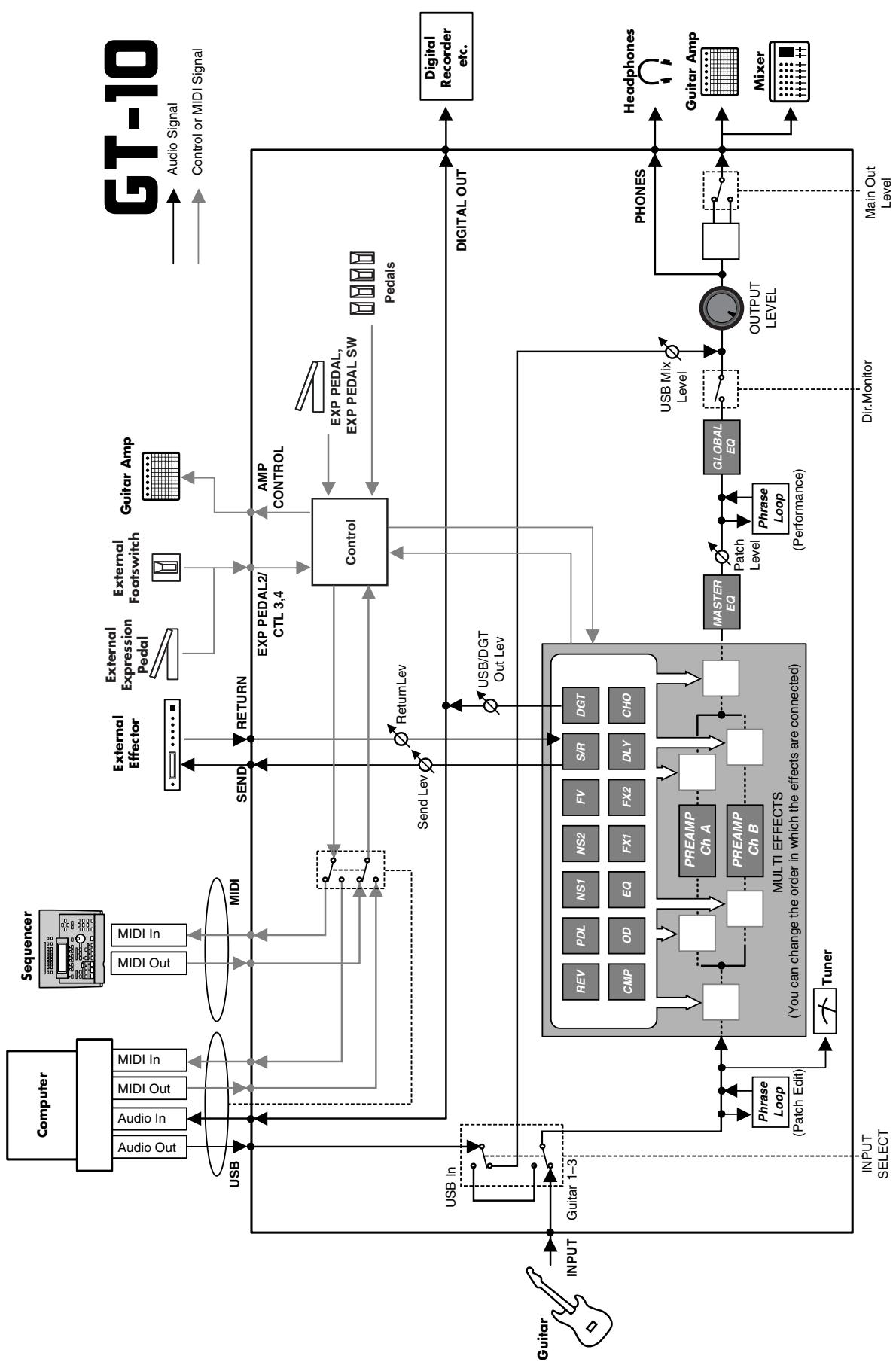
Signal Flow
MIDI Implementation Chart
GUITAR EFFECTS PROCESSOR
Model GT-10
Date: Jan. 10, 2008
Version: 1.00
MIDI Implementation Chart
| Function... | Transmitted | Recognized | Remarks | |
| Basic Channel | Default Changed | 1-16 1-16 | 1-16 1-16 | Memorized |
| Mode | Default Messages Altered | X X **** | OMNI ON/OFF X X | Memorized |
| Note Number: | True Voice | X **** | X **** | |
| Velocity | Note ON Note OFF | X X | X X | |
| After Touch | Key's Ch's | X X | X X | |
| Pitch Bend | X | X | ||
| Control Change | 0,32 1-31 33-63 64-95 | O (0-3) O X O | O * 1 O * 2 O * 2 | Bank Select |
Mode 1: OMNI ON, POLY
Mode 2: OMNI ON, MONO
O:Yes
Mode 3:OMNI OFF,POLY
Mode 4:OMNI OFF,MONO
X:No
Specifications
GT-10:Guitar Effects Processor
AD Conversion
24-bit + AF method
DA Conversion
24-bit
Sampling Frequency
44.1 kHz
Program Memories
400: 200(user) + 200(preset)
Nominal Input Level
INPUT: -10 dBu
RETURN: -10 dBu
Input Impedance
INPUT: 1 M ohm
RETURN: 220k ohms
Nominal Output Level
Coaxial type (conforms to IEC60958)
Display
132 × 64 dots graphic LCD (backlit LCD)
7 segments, 3 characters LED
Connectors
INPUT jack (1/4 inch phone type)
OUTPUT jacks L/MONO, R (1/4 inch phone type)
PHONES jack (Stereo 1/4 inch phone type)
EXT LOOP jacks SEND, RETURN (1/4 inch phone type)
AMP CONTROL jack (1/4 inch phone type)
EXP PEDAL 2/CTL3,4 jack (1/4 inch TRS phone type)
USB connector
DIGITAL OUT jack (coaxial type)
MIDI connectors IN, OUT
DC IN jack
Power Supply
DC 9 V (AC Adaptor: Roland PSB-1U)
Current Draw
800 ~mA
Dimensions
AC Adaptor (Roland PSB-1U)
Owner's Manual
Roland Service (Information Sheet)
Options
Footswitch: BOSS FS-5U
Dual Footswitch: BOSS FS-6
Expression Pedal: BOSS FV-500L/500H, Roland EV-5
Footswitch Cable: Roland PCS-31
(1/4 inch Phone plug (stereo) - 1/4 inch Phone plug (mono) x2)
- 0 dBu = 0.775 Vrms
NOTE
In the interest of product improvement, the specifications and/or appearance of this unit are subject to change without prior notice.
AF method (Adaptive Focus method)
This is a proprietary method from Roland & BOSS that vastly improves the signal-to-noise (S/N) ratio of the A/D and D/A converters.
Error Messages
If there has been a mistake in an operation or if the operation is not executed properly, an error message will appear in the display.
Please follow the instructions indicated in the message to resolve the issue.
"MIDI BUFFER FULL" "USB BUFFER FULL"
- The data cannot be processed correctly due to the high volume of MIDI messages.
Reduce the volume of MIDI messages transmitted to the GT-10.
- Transmissions from the connected device have been interrupted. This message also appears when the power to the connected device has been turned off. It does not indicate damage.
- Check to make sure no cable is disconnected and that there are no shorts.
"DATA WRITE ERROR"
- Writing to the memory for storage of user data failed.
The unit may be damaged. Consult the nearest Roland service center.
Troubleshooting
If there is no sound or other operational problems occur, first check through the following solutions. If this does not resolve the problem, then contact your dealer or a nearby Roland service station.
Problems with the sound
No sound / volume too low
Are the connection cables broken?
Try using a different set of connection cables.
Is the GT-10 correctly connected to the other devices?
Check connections with the other devices (p. 22).
Is the connected amp/mixer turned off, or the volume lowered?
Check the settings of your amp/mixer system.
Is the OUTPUT LEVEL knobs lowered?
Adjust the OUTPUT LEVEL knobs to an appropriate position (p. 24).
Is Tuner set to On?
When the volume is set to "Mute" in the Tuner mode, even the direct sound will not be output by setting the Tuner to "On" (p. 28).
Is each effect set correctly?
Use the "Changing the Connection Order of Effects (Effect Chain)" (p. 38) to check the output level of each effect. If there is an effect for which the meter does not move, check the settings for that effect.
Is "USB/DGT Out Lev" set to a low value?
Adjust the setting to an appropriate value (p. 135).
Is "PEDAL: FV: Level" or "MASTER: Patch Level" specified as an assign Target?
Move the controller to which it is assigned.
Is the power to the external device connected to the EXT LOOP jack off, or is the volume of the device turned down?
Check the settings for the connected device.
Sound from devices connected to the INPUT jack is not heard in the headphones
Is the Dir.Monitor (p. 93) set to OFF?
Set to ON.
The volume level of the instrument connected to INPUT and RETURN are too low
Could you be using a connection cable that contains a resistor?
Use a connection cable that does not contain a resistor.
Oscillating sound occurs
Is the value for any gain- or volume-related effects parameter set too high?
Lower these values.
Is the INPUT SELECT (p. 61) set to "USB In?"
When set to "USB In," audio signals may, depending on the software settings, end up looping. You can use the following methods to prevent this from happening.
- Stop playback with the software, and set Soft Thru to Off.
- Switch the software's audio input off.
- Change INPUT SELECT to "Guitar 1-3."
No change in preamp tone even after switching patches
Has the GT-10 been set to "System1-3" in Preamp mode (p. 69)?
When the GT-10 is set to "System1-3" in Preamp mode, the preamp settings do not change when patches are switched.
To make different preamp settings for individual patches, choose the "Patch" setting in Preamp mode.
Unable to change parameters with the knobs or dial
Are you using the Internal Pedal System (p. 54) in Assign?
When the Assign Source is set to "INTERNAL PDL" or "WAVE PDL," the effect parameter set as the Assign Target changes automatically. If you want to be able to change the parameters manually with the knobs and dial, first switch off Assign to deactivate the Internal Pedal System.
Is "INPUT LEVEL" (p. 50) set as the Assign Source in Assign?
When "INPUT LEVEL" is set for the Assign Source, the effect parameter set as the Assign Target changes automatically according to the level of the input from the guitar (the playing dynamics).
If you want to be able to change the parameters manually with the knobs and dial, first switch off Assign.
Other Problems
Patch does not change
Is something other than the Play screen shown in the display?
On the GT-10, patches can be selected only when the Play screen is displayed. Press [EXIT] to return to the Play screen (p. 24).
Parameters specified with Assign can't be controlled
Could the effect be switched off?
To control a parameter using the EXP Pedal or footswitch, make sure the effect that contains the parameter you intend to control is switched on.
Is Prefernc ("preference") for Pedal Function set to the "System" setting?
Even when an assignment setting has been made for the patch, the setting made for Pedal Function (p. 47) takes precedence. To enable the setting made for the patch, for Pedal Function set the preference for the relevant controller to Patch.
Do the MIDI channel settings of both devices match?
Make sure that the MIDI channels of both devices match (p. 80).
Do the controller number settings of both devices match?
Make sure that the controller number of both devices match (p. 126).
MIDI messages are not transmitted/ received
Are the MIDI cables broken?
Try another set of MIDI cables.
Is the GT-10 correctly connected to the other MIDI device?
Check connections with the other MIDI device.
Do the MIDI channel settings of both devices match?
Make sure that the MIDI channels of both devices match (p. 80).
- When you send messages from the GT-10, make sure the GT-10 is set to the settings appropriate for sending data.
Check the on/off status for transmission of program change messages (p. 84) and the settings for the controller numbers to be transmitted (p. 84).
Numerics
2X2 CHORUS 102
2x2 CHORUS 118
A
AC Adaptor 22
AC.PROCESSOR 102,112
Acoustic Processor 102, 112
ADV.COMP 102,104
Advanced Compressor 102, 104
Amp 22-23
AMP CONTROL 22,132
AMP CONTROL Jack 13
ANTI-FEEDBACK 102
Anti Feedback 102
ANTI-FEEDBACK 113
Assign 50
ASSIGN 1-8 126
AUTO RIFF 102, 111
AutoRiff 102
AUTO WAH 102-103
Auto Wah 102
B
Bank 16
Bank Change Mode 72
Bank Extent 71
BANK Pedals 12
BOTTOM 97
BulkDump 87
Bulk Load 89
C
CATEGORY 31,39
CATEGORY NAME 40
CATEGORY/ENTER Button 12
CHORUS 121
CHORUSButton 11
COMP 96
COMPButton 11
Compressor 96
Connection 14,22
Contrast 67
Control Change 79,85
CONTROLLER 137
Controller 53
Copy 42
CREATE Button 11
CTL Pedal 79
CTL Pedals 12
D
DC IN Jack 13
DEFRETTER 102, 106
Defretter 102
DELAY 119
DELAY Button 11
Dial 11
Dial Function 75
DIGITAL OUT 66
DIGITAL OUT Connector 13
Direct Monitor 93
DISPLAY MODE Button 11
Driver Mode 91
Dual-L/R 120
Dual-P 120
Dual-S 120
E
EDIT Button 11
Effect Level 38
On and Off 34
Effect Chain 38
EFFECTS SELECT 11
EQ 101
EQ Button 11
Equalizer 101
EXITButton 11
EXP Pedal 12,79
Adjusting 77
EXP Pedal Hold 73
EXP PEDAL SW 12,79
EXP PEDAL/CTL 3,4 Jack 13
Expression Pedal 22
expression pedal 22
EXT LOOP Jacks 13
External Effects 23, 26
EZ TONE 11,32,133
CREATE 32
EDIT 33
EZ Tone 20
F
Factory Reset 76
Factory Settings 76
FEEDBACKER 102, 113
Feedbacker 102
FLANGER 102, 114
Flanger 102
Foot Switch 22
FootVolume 125
FX-1 102
FX-1Button 11
FX-2 102
FX-2Button 11
G
Global 62
Global EQ 62
GRAPHIC EQ 102, 104
Graphic Equalizer 102, 104
Guitar Amp 26
GUITAR SIM. 102, 106
Guitar Simulator 102, 106
GUITAR SYNTH 102, 107
Guitar Synth 102
H
HARMONIST 102, 110
Harmonist 102
Harmonist Scale 111
HIGH 97
HUMANIZER 102, 117
Humanizer 102
1
Initialize 43
INPUT Jack 13
Input Level 61
Input Presence 61
Input Select 61
INPUT/OUTPUT 134
Internal Pedal 54, 126
Internal Pedal System 54
K
KEY 122
Knob View 35
L
LCD Contrast 67, 139
Level Meter 38
LIMITER 102, 104
Limiter 102
LINE/PHONES 25
List View 35
LOW 97
M
Main Out Level 65
Manual Mode 55
MANUAL MODE SETTING 136
Manual Settings 51
MASTER 122
MASTER BPM 122
MASTER/PEDAL FX Button 11
MIDI 79,139
MIDI IN/OUT Connectors 13
MIDI Map Select 84
MIDI Sequencer 89
MODE switch 22
Modulate 120
N
NAME
CATEGORY 40
PATCH 41
Noise Suppressor 133
NS 133
NS1 133
NS2 133
Number 16
Number Pedal 16, 57
Number Pedals 12
0
OCTAVE 102, 109
Octave 102
OD/DS 96
OD/DS Button 11
OUTPUT Jacks 13
OUTPUT L/MONO 22
OUTPUT LEVEL 24
OUTPUT LEVEL Knob 11
OUTPUT SELECT 141
Output Select 25
OUTPUT SELECT Button 11
Overdrive/Distortion 96
P
PAN 102, 115
Pan 102, 120
PARAEQ 102,105
Parameter 36
Parameter Knobs 11
Parametric Equalizer 102, 105
PATCH COPY 42
EXCHANGE 43
INITIALIZE 43
SELECT 16
WRITE 42
Patch 16,29
Patch Change Mode 68
PATCH NAME 41
PEAK 103
Pedal 47
Pedal Bend 124
Pedal Function 47
PEDAL FX 122
Pedal FX 48
Pedal Indicate 74
PHASER 102, 114
Phaser 102
PHONES Jack 13
Phrase
Deleting 59
Overdubbing 58
Recording 58
PHRASELOOP 12,135
Phrase Loop 58
PITCH SHIFTER 102, 109
Pitch Shifter 102
PLAY OPTION 136
Play Screen 23
POLARITY switch 22
POWER Switch 13
PREAMP 98
PREAMP Button 11
Preamp Mode 69
Preset Bank 29
Program Change 79
Program Change Map 84
Q
Quick Setting 35
R
RETURN 132
REVERB 121
REVERB Button 11
RING MOD. 102, 117
Ring Modulator 102, 117
RISE TIME 120
ROTARY 102, 115
Rotary 102
s
Saving a Patch 42
SELECT Button 11
SEND 132
SEND/RETURN 132
SEND/RETURN Jacks 15
Sitar 108
SITAR SIM. 102, 108
Sitar Simulator 102, 108
SLICER 102, 116
Slicer 102
SLOWGEAR 102,106
Slow Gear 102
SOUND HOLD 102, 112
Sound Hold 102
Speaker 22
Speaker Simulator 25
SUB DELAY 102, 118
Sub Delay 102
SUB WAH 102-103
Sub Wah 102
SW&PDL FUNCTION 122
Swap 43
SYSTEM 134
SYSTEMButton 11
T
T.WAH 102
Target 53
TARGETPARAMETER 127
TONE MODIFY 102, 105
Tone Modify 102
TOP 97
Total Noise Suppressor 63
Total REVERB 64
Touch Wah 102
TREMOLO 102, 115
Tremolo 102
TUNER 26,134
Tuner 26
TUNER/BYPASS Button 12
TYPE 98,119
U
UNI-V 102, 115
USB 90
USB Connector 13
USB Driver 90
User Bank 29
User Patch 29,43
User Phrase 112
User Quick Setting 44
User Scale 111
V
VIBRATO 102, 116
Vibrato 102
View
Knob 35
List 35
Volume 22
Volume-swell Effect 106
W
WAH 123
Warp 120
Wave Pedal 54, 126
WAVE SYNTH 102
Wave Synth 102
WAVE SYNTH. 107
Write 42
WRITE Button 12


有关产品中所含有害物质的说明
This symbol indicates that in EU countries, this product must be collected separately from household waste, as defined in each region. Products bearing this symbol must not be discarded together with household waste.

- Microsoft and Windows are registered trademarks of Microsoft Corporation.
- Windows® is known officially as: "Microsoft® Windows® operating system."
- Apple and Macintosh are registered trademarks of Apple Inc.
- Mac OS is a trademark of Apple Inc.
- All product names mentioned in this document are trademarks or registered trademarks of their respective owners.
For the U.K.
IMPORTANT: THE WIRES IN THIS MAINS LEAD ARE COLOURED IN ACCORDANCE WITH THE FOLLOWING CODE.
BLUE: NEUTRAL
BROWN: LIVE
As the colours of the wires in the mains lead of this apparatus may not correspond with the coloured markings identifying the terminals in your plug, proceed as follows:
The wire which is coloured BLUE must be connected to the terminal which is marked with the letter N or coloured BLACK. The wire which is coloured BROWN must be connected to the terminal which is marked with the letter L or coloured RED.
Under no circumstances must either of the above wires be connected to the earth terminal of a three pin plug.

This product complies with the requirements of EMC Directive 2004/108/EC.
-For EU Countries
For the USA
FEDERAL COMMUNICATIONS COMMISSION RADIO FREQUENCY INTERFERENCE STATEMENT
This equipment has been tested and found to comply with the limits for a Class B digital device, pursuant to Part 15 of the FCC Rules. These limits are designed to provide reasonable protection against harmful interference in a residential installation. This equipment generates, uses, and can radiate radio frequency energy and, if not installed and used in accordance with the instructions, may cause harmful interference to radio communications. However, there is no guarantee that interference will not occur in a particular installation. If this equipment does cause harmful interference to radio or television reception, which can be determined by turning the equipment off and on, the user is encouraged to try to correct the interference by one or more of the following measures:
- Reorient or relocate the receiving antenna.
- Increase the separation between the equipment and receiver.
- Connect the equipment into an outlet on a circuit different from that to which the receiver is connected.
- Consult the dealer or an experienced radio/TV technician for help.
This device complies with Part 15 of the FCC Rules. Operation is subject to the following two conditions:
(1) this device may not cause harmful interference, and
(2) this device must accept any interference received, including interference that may cause undesired operation.
Unauthorized changes or modification to this system can void the users authority to operate this equipment.
This equipment requires shielded interface cables in order to meet FCC class B Limit.
For Canada
NOTICE
This Class B digital apparatus meets all requirements of the Canadian Interference-Caising Equipment Regulations.
AVIS
DECLARATION OF CONFORMITY Compliance Information Statement
Model Name :
Type of Equipment :
Responsible Party :
Address :
Telephone :
GT-10
Guitar Effects Processor
Roland Corporation U.S.
5100 S.Eastern Avenue, Los Angeles, CA 90040-2938
(323) 890-3700