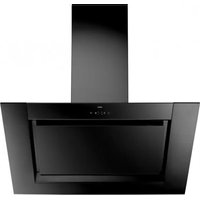
WS9192FM - Range hood Atag - Free user manual and instructions
Find the device manual for free WS9192FM Atag in PDF.


| Product type | Decorative hood |
| Brand | Atag |
| Model | WS9192FM |
| Dimensions (W x D x H) | 898 x 500 x 600 mm |
| Net weight | 15 kg |
| Power supply | 220-240 V, 50/60 Hz |
| Maximum motor power | 250 W |
| Lighting | LED, 2 x 3 W |
| Noise level (min/max) | 40 / 68 dB(A) |
| Maximum airflow | 600 m³/h |
| Exhaust mode | External extraction or recirculation |
| Grease filter | Metallic, dishwasher-safe |
| Charcoal filter (optional) | Yes, for recirculation mode |
| Control type | Electronic touch controls |
| Number of speeds | 4 |
| Boost function | Yes |
| Energy class | A |
| Maintenance | Regular cleaning of filters and surface |
| Safety | Automatic delayed shut-off |
| Spare parts | Filters, LED bulbs, remote control |
| General information | Manual in several languages available at notice-facile.com |
Frequently Asked Questions - WS9192FM Atag
User questions about WS9192FM Atag
0 question about this device. Answer the ones you know or ask your own.
Ask a new question about this device
Download the instructions for your Range hood in PDF format for free! Find your manual WS9192FM - Atag and take your electronic device back in hand. On this page are published all the documents necessary for the use of your device. WS9192FM by Atag.
USER MANUAL WS9192FM Atag
instructions for use cooker hood
anvendelse emhætte
ATAG
WS9111FM WS9192FM

natural_image
Exterior view of a stainless steel kitchen air conditioner unit (no text or symbols visible)NL
natural_image
Hand pointing at a car license plate with a right-turn arrow (no text or symbols)Koolstofffilter
natural_image
Illustration of hands installing or adjusting a mechanical component with arrows indicating motion (no text or symbols)Montage
deel.
natural_image
Diagram of a cylindrical object inside a transparent container with an arrow indicating direction, no text or symbols present.Afvoeren
natural_image
Hand pointing at a car license plate with a curved arrow symbol (no text or labels)natural_image
Illustration of hands installing or adjusting a mechanical component with arrows indicating motion (no text or symbols)Montage
partie inférieure.
natural_image
Diagram of a cylindrical object inside a transparent container with an arrow indicating direction, no text or symbols present.Élimination
natural_image
Hand pointing at a car license plate with a right-turn arrow (no text or symbols)natural_image
Illustration of hands installing or adjusting a mechanical component with arrows indicating motion (no text or symbols)Der Kohlefilter
Montage
natural_image
Diagram of a cylindrical object inside a transparent container with an arrow indicating direction, no text or symbols present.Entsorgen
natural_image
Symbol of a trash bin with crossed lines indicating no waste or discharge, and a blank rectangular base (no text or numbers present)| Cleaning | 8 | |
| Removing the grease filter | 9 | |
| Replacing the carbon filter | 9 | |
| Lighting | 10 |
Installation
| General | 11 | |
| Electric connection | 12 | |
| Mounting the extraction unit 13 |
Appendix
| Disposal of packaging and appliance | 15 |
Introduction
Please read these instructions carefully to become informed quickly of all possibilities offered by this appliance. These instructions contain information for your safety and information about the maintenance of the appliance.

Please retain the operating and installation instructions. Any subsequent user of this appliance may also benefit from them.

Please read the separate safety instructions first before use.
Description
flowchart
graph TD
    A["A"] --> Power["Power Icon"]
    B["B"] --> Power
    G["G"] --> Power
    E["E"] --> Power
    C["C"] --> Power
    D["D"] --> Power
    Power --> 1["1"]
    Power --> 2["2"]
    Power --> 3["3"]
    Power --> F["F"]
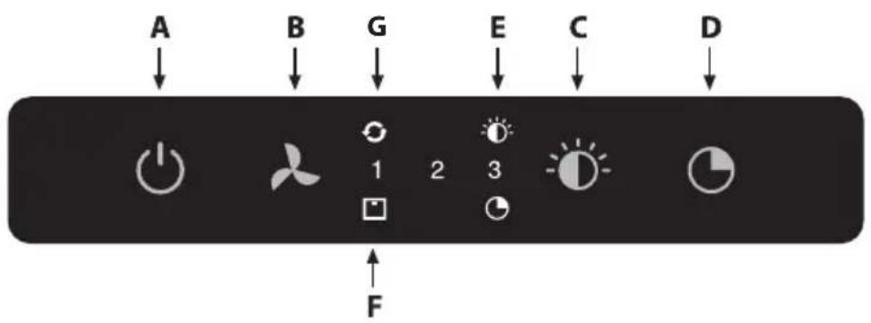
A: Switching the fan on/off
B: Lowering/increasing air extraction capacity
C: Switching lighting on/off and dimming the lighting
D: Timer function
E: Lighting indicator
F: Filter indicator
G: Clean air indicator
Operating instructions

flowchart
graph TD
    A["A"] --> Power["Power Icon"]
    B["B"] --> Power
    G["G"] --> Power
    E["E"] --> Power
    C["C"] --> Power
    D["D"] --> Power
    Power --> 1["1"]
    Power --> 2["2"]
    Power --> 3["3"]
    Power --> 4["4"]
    Power --> F["F"]
Switching the fan on and off
- Use the On/Off button (A) to switch on the fan and select the desired setting with button 'B'.
If you press the button (B) once, when the hood is switched off, the hood will be switched on at the lowest setting. By pressing the button (B) again, you select a higher setting. You can select one of three settings plus an intensive setting.
One LED will light up at setting 1; two will light up at setting 2 and all three will light up at setting 3.
- Switch on the intensive setting by pressing 'B' and holding it for min. 5 seconds until the third LED starts flashing.
You switch off the intensive setting early by pressing button 'A', as a result of which the hood switches off, or by pressing button 'B', which will result in the hood switching back to the previously selected setting.

The intensive setting automatically switches the speed back to the previously selected setting after 10 minutes.
Switching the lighting on and off
- Use button 'C' to switch the lighting on and off and adjust the intensity of the light.
Lighting indicator 'E' will light up as soon as the lighting has been switched on. The lighting can be dimmed steplessly.
Clean Air function:
The Clean Air function allows you to freshen the air in your kitchen automatically for a maximum of 24 hours.
- Please ensure that the cooker hood is switched off.
- Press button ‘A’ until the ‘Clean Air’ indicator ‘G’ lights up.
The cooker hood switches on automatically for 10 minutes every hour at the lowest speed setting. During extraction, LED 1 will light up. If the hood switches off after 10 minutes, indicator 'G' will flash until the hood switched on again after 50 minutes. - Switch off the Clean Air function early by pressing a random button (except the one for lighting).
Switching on the Timer
- Switch on the cooker hood with button 'A'.
- Adjust the extraction strength level with button 'B'.
The timer can be switched on with every setting, except the intensive setting. - Press the Timer button 'D'.
The cooker hood switches off automatically after 15 minutes. Switch off the Timer function by pressing button 'D' again or by switching off the cooker hood with button 'A'.
Grease filter indication
After 30 working hours, the filter indication 'F' will light up.
- Clean the grease filter.
- Reset the filter indicator. While the hood is switched off, press button 'B' for 3 seconds until the filter indicator is turned off.
Carbon filter indicator
After 120 working hours, the filter indication 'F' will flash.
- Replace the carbon filters.
- Reset the filter indicator. While the hood is switched off, press button 'B' for 3 seconds until the filter indicator is turned off.
Cleaning

Important! Before all maintenance, disconnect the cooker hood from the mains power first by pulling the plug out of the socket or by turning off the home's master switch. The hood needs to be cleaned regularly, both inside as well as outside (at least as frequently as the grease filter cleaning). Do not use abrasive cleaners.
Do not use alcohol!
Important! If the instructions regarding cleaning the appliance or cleaning or replacing the filters are not followed, this can cause a fire. These instructions need to be observed!
The manufacturer is not liable for damage to the motor or fire damage resulting from incompetent maintenance or from non-adherence to the above safety instructions.
Cooker hood
Clean the cooker hood with soapy water and a soft cloth. Then wash off with clean water. Do not use aggressive cleaning agents such as caustic soda. The cooker hood finish stays in good condition if it is buffed periodically following the application of wax.

Stainless steel cooker hoods
Do not use scouring pads or other abrasive cleaners on stainless steel cooker hoods. Finish with a non-abrasive, non-polishing agent and buff with the structure of the stainless steel.
Metal grease filters
Metal grease filters should be cleaned once a month (or when indicated by the filter cleaning indicator – if present on the model) using a neutral cleaning agent, either by hand or in the dishwasher on a short, low-temperature programme. Place the grease filters with the openings facing downwards in the dishwasher so the water can run out of the filter. Aluminium grease filters become dull as a result of dishwasher cleaning agents. This is normal and does not effect the working.
Grease filters

natural_image
Hand pointing at a car license plate with a right-turn arrow (no text or symbols)Carbon filter

natural_image
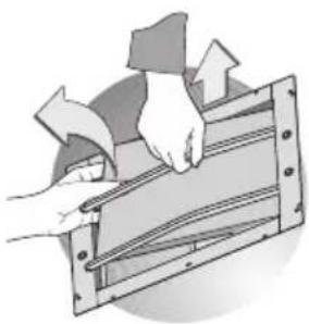
Illustration of hands installing or adjusting a mechanical component with arrows indicating motion (no text or symbols)Removing grease filters
Switch off the mains power! Remove the plug from the socket or turn off the switch in the fuse box. Open the panel and pull the special handle to remove the filter.
The carbon filter
Use a carbon filter if the cooker hood is not connected to a outlet duct. Put a carbon filter frame into position for this, which can be purchased separately. This needs to be done once-only.
- Open the panel.
- Remove the grease filter.
- Attach the carbon filter to the grille.
- Put the grease filter into position.
The regenerable active carbon filter must be washed by hand with neutral cleaning products that are not abrasive, or in the dishwasher at a maximum temperature of 65 °C (the washing should be done without any plates, dishes, cups, etc. in the machine).
Remove the excess water without damaging the filter, remove the holder and let the filter dry in the oven for at least 15 minutes at a maximum temperature of 100 °C . The filters must be replaced after no more than 3 years, or if the filter has been damaged. It is important that the grease filter and the regenerable active carbon filter are properly dry before they are put into position again.

Operation:
- When using the carbon filter, more sound is created than when using the cooker hood with an extractor.
- The operation of a carbon filter is optimal at a lower motor speed. You should, therefore, avoid using the boost function.
Lighting

Defective LED lighting must be replaced by an installer.
General
This appliance should be connected to the mains power by a registered installer, who knows and applies the correct safety specifications. The appliance meets European requirements.
Important information:
- The distance between the lowest point of the cooker hood and a gas hob should be at least 65 cm. With an electric, ceramic or induction hob this distance should be at least be 45 cm.
- If the appliance is connected to an existing ducting outlet, no other appliances should be connected to that outlet (such as a heater or boiler).
- Follow the applicable local regulations regarding the ventilation of gas appliances.
- With a short exhaust-air pipe and few bends, the cooker hood will work better.
• Prior to drilling check that there are no pipes or cables present. - The cooker hood connection pipe is 120 mm or 150 mm in diameter. It is best to use this diameter for the ducting pipe.
Electrical connection

This appliance is manufactured in class I, it must therefore be connected to the earth system.
Make sure the supply voltage ratings correspond with those stated on the appliance data plate. The connection to the mains is carried out as follows:
BROWN = phase L
BLUE = phase N
YELLOW/GREEN = Earth
During the electrical connection make sure that the electrical socket is equipped with earth connection.
This canopy hood has been provided with a power plug. When installing the hood, make sure that this plug remains accessible.
Attention:
If you want to make a fixed connection, ensure that a multi-pole switch with a distance between contacts of 3 mm is installed in the supply cable.
max. 140 cm

Assembly
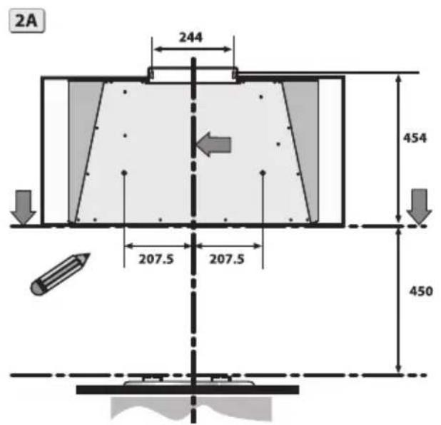
- Outline the underside of the hood on the wall, taking into account the minimum distance between the hood and the cooking section.
- Mark the 4 holes using the template.
- Place the 4 wall plugs 'A' and the 2 screws 'B'.
- Please note! Set screws 'D' must be tightened firmly.

- Hang the cooker hood onto the 2 screws 'B'.
- Ensure the cooker hood is level with the screws 'D'.
- Screw the hood to the wall with the 2 screws 'B'.

- Place the wall socket inside the telescopic chimney.
- Connect the flange to the air extraction opening using an air duct.
- Place the bottom telescopic chimney on the cooker hood.
- Adjust the width of the hanging bracket of the upper telescopic chimney.
- Mark off and drill the holes to attach the hanging bracket.
- Place the 2 wall plugs.
- Screw the hanging bracket to the wall with the 2 screws 'A'. Align the hanging brackets with the cooking hood. Take the distance to the ceiling into account.
- Slide the upper telescopic chimney from above in the bottom

section.
- Slide the upper telescopic chimney upwards and attach this to the hanging bracket with the 2 screws 'B'.

Please note; Use the appropriate screws and plugs for mounting the cooker hood, which are suitable for the type of wall (concrete, plaster board, etc.) to which the cooker hood is being attached.

natural_image
Diagram of a cylindrical object inside a transparent container with an arrow indicating direction, no text or symbols present.Disposal
Disposal of packaging and appliance
Sustainable materials have been used during manufacture of this appliance. This appliance must be disposed of responsibly at the end of its service life. Ask your local authorities for more information about how to do this.
The appliance packaging is recyclable. The following materials may have been used:
- cardboard;
• polyethylene film (PE);
• CFC-free polystyrene (PS rigid foam).
Dispose of these materials in a responsible manner and in accordance with government regulations.

The product has been marked with a crossed-out dustbin symbol to remind you of the obligation to dispose of electrical household appliances separately. This means that the appliance may not be included with normal domestic refuse at the end of its service life. The appliance must be taken to a special municipal centre for separated waste collection or to a dealer providing this service.
Separate processing of household appliances prevents the potentially negative consequences for the environment and health that can arise as a result of inappropriate processing. It ensures that the materials of which the appliance is composed can be recovered to obtain significant savings in energy and raw materials.
CE
Declaration of Conformity
We hereby declare that our products satisfy the applicable European directives, orders and regulations, as well as the requirements stated in the referenced standards.
Din emhætte
natural_image
Hand pointing at a car license plate with a right-turn arrow (no text or symbols)Kulfilter

natural_image
Illustration of hands installing or adjusting a mechanical component with arrows indicating motion (no text or symbols)Fjerne fedtfiltre
Montering
natural_image
Diagram of a cylindrical object inside a transparent container with an arrow indicating direction, no text or symbols present.Bortskaffelse
natural_image
Symbol of a trash bin with crossed x-marks and a blank base (no text or numbers)



- ATAG
- Koolstofffilter
- Montage
- Afvoeren
- Élimination
- Der Kohlefilter
- Entsorgen
- Introduction
- Description
- Operating instructions
- Switching the fan on and off
- Switching the lighting on and off
- Clean Air function:
- Switching on the Timer
- Grease filter indication
- Carbon filter indicator
- Cleaning
- Do not use alcohol!
- Cooker hood
- Stainless steel cooker hoods
- Metal grease filters
- Grease filters
- Carbon filter
- Removing grease filters
- The carbon filter
- Operation:
- Lighting
- General
- Important information:
- Electrical connection
- This appliance is manufactured in class I, it must therefore be connected to the earth system.
- Attention:
- Assembly
- Disposal
- Disposal of packaging and appliance
- Declaration of Conformity
- Kulfilter
- Fjerne fedtfiltre
- Montering
- Bortskaffelse
Brand : Atag
Model : WS9192FM
Category : Range hood