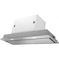
WU9011HM - Range hood Atag - Free user manual and instructions
Find the device manual for free WU9011HM Atag in PDF.


| Product type | Decorative hood |
| Brand | Atag |
| Model | WU9011HM |
| Width | 90 cm |
| Depth | 50 cm |
| Height (min-max) | 60-110 cm |
| Net weight | 15 kg |
| Power supply | 230 V ~ 50 Hz |
| Motor power | 200 W |
| Lighting | LED, 2 x 3 W |
| Number of speeds | 3 + intensive |
| Max airflow | 650 m³/h |
| Max noise level | 65 dB(A) |
| Filter type | Washable aluminum grease filter |
| Optional carbon filter | Yes, model AT6310 |
| Evacuation mode | Extraction or recirculation |
| Duct diameter | 150 mm |
| Energy class | A |
| Controls | Push buttons |
| Material | Stainless steel and tempered glass |
| Grease filter cleaning | Dishwasher safe or hand wash |
| Repairability index | 8.2 / 10 |
Frequently Asked Questions - WU9011HM Atag
User questions about WU9011HM Atag
0 question about this device. Answer the ones you know or ask your own.
Ask a new question about this device
Download the instructions for your Range hood in PDF format for free! Find your manual WU9011HM - Atag and take your electronic device back in hand. On this page are published all the documents necessary for the use of your device. WU9011HM by Atag.
USER MANUAL WU9011HM Atag
instructions for use cooker hood
natural_image
Hand pointing at a circular diagram with an arrow and angle marker (no text or symbols)Koolstofffilter
natural_image
Diagram of a mechanical or biological structure with green arrows indicating rotational or directional movement (no text or symbols)
natural_image
Diagram of a biological or mechanical structure with green arrows indicating direction, no text or symbols presentVerlichting
natural_image
Diagram of a mechanical or electrical component with three input/output ports and a central box, connected by wires (no text or symbols present)Montage

natural_image
Diagram showing a mechanical component with a green arc and dashed outline, no text or symbols present
natural_image
Illustration of a hand interacting with a smartphone displaying a green leaf symbol (no text or symbols present)- Open het paneel.
natural_image
Close-up of a mechanical component with green and black parts, no visible text or symbolsnatural_image
Pure diagram of a rectangular frame with arrows indicating directional arrows, no text or symbols present.
natural_image
Pure technical diagram of a mechanical assembly with no text, numbers, or symbols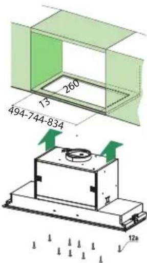
natural_image
Symbol of a trash bin with crossed lines indicating no waste or discharge (no text or numbers present)natural_image
Hand holding a tool interacting with a circular diagram showing a road sign (no text or symbols present)Filtres à charbon

natural_image
Diagram of a biological or mechanical structure with green arrows indicating rotational or directional movement (no text or symbols)
natural_image
Diagram of a biological or mechanical structure with green arrows indicating direction, no text or symbols presentÉclairage
natural_image
Diagram of a mechanical device with a hand interacting with a sensor or sensor, showing wiring and components (no text or symbols present)Montage
natural_image
Diagram showing a mechanical assembly with a component and a green arc indicating motion (no text or symbols)
natural_image
Illustration of a hand pressing a green arrow on a smartphone screen (no text or symbols)natural_image
Close-up of two mechanical components with green connectors and black connectors, no visible text or symbolsnatural_image
Pure diagram of a rectangular frame with arrows indicating directional flow, no text or symbols present.
natural_image
Pure technical diagram of a mechanical assembly with no text, numbers, or symbols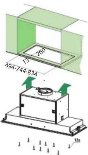
natural_image
Symbol of a trash bin with crossed lines indicating no waste or discharge (no text or numbers present)natural_image
Hand pointing at a circular diagram with a curved arrow, no text or symbols presentKohlefilter
natural_image
Diagram of a car with green arrows indicating rotational motion around the wheel (no text or symbols)
natural_image
Diagram of a biological structure with green arrows indicating directional flow, no text or symbols presentLampen
natural_image
Diagram of a mechanical or electrical component with three labeled sensors and wiring, no text or symbols present.Montage


natural_image
Illustration of a hand pressing a green arrow on a smartphone screen (no text or symbols)natural_image
Close-up of two mechanical connectors with green and black plastic components, no visible text or symbolsnatural_image
Pure diagram of a rectangular frame with arrows indicating directional arrows, no text or symbols present.
natural_image
Pure technical diagram of a mechanical assembly with no text, numbers, or symbols
natural_image
Symbol of a trash bin with crossed lines indicating no waste or discharge (no text or numbers present)| Description | 4 | ||||
| Introduction | 4 | ||||
| Use | |||||
| Controls | 5 | ||||
| Maintenance | |||||
| Cleaning | 7 | ||||
| Removing the grease filters | 8 | ||||
| Replacing the carbon filter | 8 | ||||
| Changing | the | light | bulbs | ||
| Installation | |||||
| General | 9 | ||||
| Electrical connection | 1 | ||||
| Mounting the canopy hood | 11 | ||||
| Appendice | |||||
| Disposal of appliance and packaging | 12 | ||||
Description

A Switch fan on/off
B Reduce extractor capacity
C Increase extractor capacity
D Engage intensive mode
E Clean air function/filter indication
F Timer function
G Switch lighting on/off
H Dim lighting
I Display
Introduction
This user manual gives you a quick overview of all the possibilities offered by the appliance. You will find information on safety measures and maintaining the appliance.

Please retain this user manual and the installation guide.
They may be of use to future users of the appliance.
Declaration of conformity
We declare that our products meet the applicable European Directives, Decisions and Regulations and the requirements listed in the standards referenced.

Read the separate safety instructions before using the device!
Controls

Switching the fan on and off
- Switch the fan on with the on/off button (A) and select the desired extractor setting with buttons 'B' and 'C'.
The 'I' display indicates which setting has been selected.
- Use button 'D' to switch on the intensive setting.
“HI” appears in the ‘I’ display.
After 10 minutes the intensive mode is automatically reduced to the setting previously selected.
Switching the lighting on and off
- Use the 'G' button to switch the lighting on and off.
Dimming the lighting
- Dim the lighting with button 'H'.
The strength of the lighting varies between maximum and minimum, and vice-versa.
Clean Air function:
With the Clean Air function you can refresh the air in the kitchen over maximum 24 hours.
- Make sure the extractor cap has been switched off.
- Press on the Clean Air button 'E'.
Every hour, the extractor cap will switch on for 10 minutes automatically, at the lowest extraction setting. The display reads "24" and an indicator flashes at the bottom right.
Switching on the timer
- Switch on the extractor cap with button 'A'.
- Set the extraction strength with buttons 'B' and 'C'.
- Press the Timer button 'F'.
The extractor cap switches off automatically after 30 minutes. Switch off the Timer function by pressing button 'F' again, or by switching off the extractor cap with button 'A'. The display shows the selected speed and the remaining time.
Grease filter indicator
After 100 hours of use the "FF" indicator is shown in the display.
- Clean the grease filters.
- Reset the filter indicator. While the cap is switched off, press button 'E' for 3 seconds until the filter indicator disappears.
Carbon filter indicator
After 200 hours of use the "EF" indicator is shown in the display.
- Replace the carbon filters.
- Reset the filter indicator. While the cap is switched off, press button 'E' for 3 seconds until the filter indicator disappears.
Cleaning

Attention! Before performing any maintenance operation, isolate the hood from the electrical supply by switching off at the connector and removing the connector fuse. Or if the appliance has been connected through a plug and socket, then the plug must be removed from the socket.
The cooker hood should be cleaned regularly (at least with the same frequency with which you carry out maintenance of the fat filters) internally and externally. Do not use abrasive products. Do not use alcohol!
Attention! Failure to carry out the basic cleaning recommendations of the cooker hood and replacement of the filters may cause fire risks. Therefore, we recommend oserving these instructions.
The manufacturer declines all responsibility for any damage to the motor or any fire damage linked to inappropriate maintenance or failure to observe the above safety recommendations.
Cooker hood
Clean the cooker hood with soapy water and a soft cloth. Then wipe with clean water to rinse. Do not use aggressive cleaning agents such as soda. The cooker hood paintwork will stay looking nice if you wax it occasionally.

Stainless steel canopy hoods
Do not use any sort of scourer. Treat with a stainless steel care product and polish with the structure of the stainless steel.
Metal grease filters
These must be cleaned once a month (or when the filter saturation indication system – if envisaged on the model in possession – indicates this necessity) using non aggressive detergents, either by hand or in the dishwasher, which must be set to a low temperature and a short cycle. The openings must be placed downwards to let the water run out of the filters. The cleaning agents will make the aluminium filter turn dull, this is normal.
Grease filters
natural_image
Hand pointing at a circular diagram with a checkmark and arrow symbol (no text or labels)Removing the grease filters
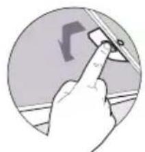
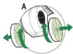
Switch off the electricity! Remove the plug from the socket or switch the electricity off at the mains. Open the panel and pull the special handle to remove the filter.
natural_image
Diagram of a mechanical or fluidic device with green arrows indicating rotational flow, no text or symbols present.Replacing the carbon filter
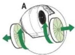
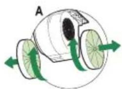
The carbon filter must always be used if the cooker hood is not ducted.
- Open the panel.
- Remove the grease filters.
- Fit the carbon filter by wedging it into the casing (D).
- Replace the filter grids in the extractor hood.

natural_image
Diagram of a biological or mechanical structure with green arrows indicating direction, no text or symbols presentNote:
- Saturation of the activated charcoal will eventually occur after more or less prolonged use, depending on the type of cooking and how frequently the grease filter is cleaned.
- In all cases it is necessary to replace the cartridge at least every four months.
- DO NOT wash or reuse the carbon filter. Saturated carbon is not environmentally friendly, change the filter regularly.
Lighting
Changing the light bulbs
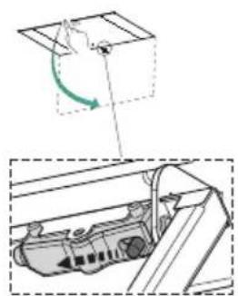
Faulty LEDs must be replaced by a professional installer.
General
This appliance should be connected to the power supply by a recognized fitter who is familiar with, and works according to the correct safety regulations. This appliance meets the European requirements.
Important that you know:
- The minimum distance between the supporting surface for the cooking vessels on the gashob and the lowest part of the range hood must be not less than 65 cm. For use with an electric, ceramic or induction hob, this distance must be at least 50 cm.
- If the cooker hood is to be fitted to an existing duct no other appliances, such as a geyser or heater, may be connected to that same duct.
- Consider local regulations with respect to the ventilation of gas appliances.
- The shorter the duct, and the fewer the bends in it, the better the cooker hood will work.
- Before you start drilling check that there are no installation cables present.
- The connecting pipe for the cooker hood has a diameter of 120 or 150 mm. It is best also to use a flue pipe of the same diameter.
- The installation material supplied with this range hood is designed for fixing to reinforced concrete or masonry walls. For some types of walls you may need special plugs and screws.
Electrical connection
This appliance is manufactured in class I, it must therefore be connected to the earth system.
Make sure the supply voltage ratings correspond with those stated on the appliance data plate. The connection to the mains is carried out as follows:
BROWN = phase L
BLUE = phase N
YELLOW/GREEN = Earth

During the electrical connection make sure that the electrical socket is equipped with earth connection.
This canopy hood has been provided with a power plug. When installing the hood, make sure that this plug remains accessible.
Attention:
If you want to make a fixed connection, ensure that a multi-pole switch with a distance between contacts of 3 mm is installed in the supply cable.
max. 120 mm

Montage
natural_image
Diagram showing a mechanical component with a green arc and dashed outline, no text or symbols present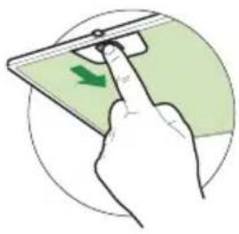
natural_image
Illustration of a hand pressing a green arrow on a smartphone screen (no text or symbols)- Open the panel.
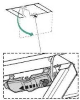
- Remove the grease filter.
- Interrupt the plug connection of the controls.

natural_image
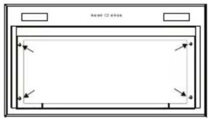
Close-up of two mechanical components with green and black parts, no visible text or symbols- First remove the 6 screws (2 on the left, 2 on the right, 2 on the front), followed by the frame.
natural_image
Pure technical diagram of a rectangular frame with corner arrows, no text or symbols present
natural_image
Pure technical diagram of a mechanical assembly with no text, numbers, or symbols
- Use a saw to create a recess in the bottom side of the cupboard (at a distance of at least 650 mm from a gas hob). Refer to the measurement drawing for this.
- Attach the unit with the 10 screws provided (12a).
- Put the frame into position.
- Restore the plug connection of the controls.
- Put the grease filter into position and close the panel.
Disposal
Disposal of appliance and packaging
By ensuring this product is disposed of correctly, you will help prevent potential negative consequences for the environment and human health, which could otherwise be caused by inappropriate waste handling of this product. The local authorities can provide you with the relevant information.
The packaging of this appliance is recyclable. It could have been made from:
- cardboard;
- polythene foil (PE);
- CFK-free polystyrene (PS-hard foam).

You need to dispose of these materials responsibly in accordance with official regulations.
To draw attention to the fact that the segregated processing of electric household appliances is compulsory, this appliance carries the symbol of a crossed-out dustbin. This means that at the end of its working life, you may not dispose of the appliance as household refuse. Instead, you should hand it in at a special refuse collection centre run by the local authority or at a dealer's providing this service.
Segregated processing of household appliances avoids any negative effects on the environment and public health that might otherwise occur.
It enables the recovery of the materials used in the production of this appliance, thus realising considerable savings in terms of raw materials and energy.
CE
Declaration of conformity
We hereby declare that our products satisfy the applicable European directives, orders and regulations, as well as the requirements stated in the referenced standards.
Emhætte
natural_image
Hand pointing at a curved arrow symbol on a circular background (no text or labels)
natural_image
Diagram of a mechanical or fluidic device with green arrows indicating rotational flow, no text or symbols present.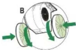
natural_image
Diagram of a biological or mechanical structure with green arrows indicating direction, no text or symbols presentBelysning
Montering

natural_image
Diagram showing a mechanical component with a green arc indicating rotation or motion, enclosed in a dashed box (no text or symbols)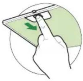
natural_image
Illustration of a hand inserting a green arrow on a device (no text or symbols)- Åbn panelet.
natural_image
Close-up of two mechanical components with green and black parts, no visible text or symbolsnatural_image
Pure technical diagram of a rectangular frame with four corner arrows indicating direction (no text or symbols)
natural_image
Pure technical diagram of a mechanical assembly with no text, numbers, or symbols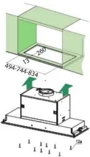



- Koolstofffilter
- Verlichting
- Montage
- Filtres à charbon
- Éclairage
- Kohlefilter
- Lampen
- Description
- Introduction
- Declaration of conformity
- Read the separate safety instructions before using the device!
- Controls
- Switching the fan on and off
- Switching the lighting on and off
- Dimming the lighting
- Clean Air function:
- Switching on the timer
- Grease filter indicator
- Carbon filter indicator
- Cleaning
- Cooker hood
- Stainless steel canopy hoods
- Metal grease filters
- Grease filters
- Removing the grease filters
- Replacing the carbon filter
- Note:
- Lighting
- Changing the light bulbs
- General
- Important that you know:
- Electrical connection
- Attention:
- Disposal
- Disposal of appliance and packaging
- Belysning
- Montering
Brand : Atag
Model : WU9011HM
Category : Range hood