
CWB 6441 - Cooker BEKO - Free user manual and instructions
Find the device manual for free CWB 6441 BEKO in PDF.
| Product type | Extractor hood |
| Brand | BEKO |
| Model | CWB 6441 |
| Power supply | 230 V / 50 Hz (according to rating plate) |
| Number of speeds | 3 |
| Lighting | 2 lamps of 40 W |
| Installation type | Extracting (external venting) or recirculating (recycling) with optional charcoal filter |
| Minimum installation distance | 650 mm between the cooking surface and the bottom of the hood |
| Filters | Washable metal filters (dishwasher or soapy water) and charcoal filters (replacement every 2 months, optional) |
| Metal filter maintenance | Cleaning every 2 months |
| Insulation class | Class II (no earthing needed) |
| Controls | Switches or buttons (depending on version) for lighting and speeds |
| Material | Stainless steel (estimate) |
| Width | 60 cm (estimate for this model) |
Frequently Asked Questions - CWB 6441 BEKO
User questions about CWB 6441 BEKO
0 question about this device. Answer the ones you know or ask your own.
Ask a new question about this device
Download the instructions for your Cooker in PDF format for free! Find your manual CWB 6441 - BEKO and take your electronic device back in hand. On this page are published all the documents necessary for the use of your device. CWB 6441 by BEKO.
USER MANUAL CWB 6441 BEKO
Instructions Manual INDEX
WARNING - COMPONENTS 14
INSTALLATION 15
USE - MAINTENANCE 16
IPOEIOHSEI-EAPTHMATA 38
EIGATAZTAZH 39
XPHSH - ΣYNTHPHSH 40
This appliance has been designed for use as either an EXTRACTION (ducting to the outside) or RECIRCULATION (filtering) hood. The measurements contained on the drawings in this booklet refer to two models of cooker hood. Therefore, it is essential that you refer to the correct drawing when taking measurements for installation.
- The minimum distance between the cooking surface and the metal grease filters on the underside of the hood must be 650mm .
- This cooker hood must be installed in accordance with the installation instructions and all requirements must be adhered to.
- If the room where the cooker hood is to be used contains a fuel burning appliance such as a central heating boiler then its flue must be of the room sealed or balance flue type.
- If other types of flue or appliances are fitted ensure that there is an adequate supply of air to the room.
- When the range hood and appliance supplied with energy other than electricity are simultaneously in operation, the negative pressure in the room must not exceed 4Pa (4x10^-5bar)
- The ducting system for this appliance must not be connected to any ventilation system which is being used for any other purpose.
- The ducting system for this appliance must not be connected to any existing ventilation system which is being used for any other purpose.
- Do not leave naked flames or carry out flambe cooking under this cooker hood.
- This appliance is not intended for use by persons (including children) with reduced physical, sensory or mental capabilities, or lack of experience and knowledge, unless they have been given supervision or instruction concerning use of the appliance by a person responsible for their safety.
- Children should be supervised to ensure that they do not play with the appliance
CONNECTING THE POWER CABLE TO THE MAINS POWER SUPPLY
Before installation, check that the mains voltage indicated on the rating plate inside the appliance corresponds to the voltage available in your home. If the Hood is not fitted with a plug, fit the power cable with a plug of a type approved for the load indicated on the rating plate; when connecting directly to the mains, insert an omnipolar circuit breaker with a minimum contact aperture of 3mm and a size suitable for the load in question between the appliance and the mains supply, making sure it is of a type that complies with current regulations.
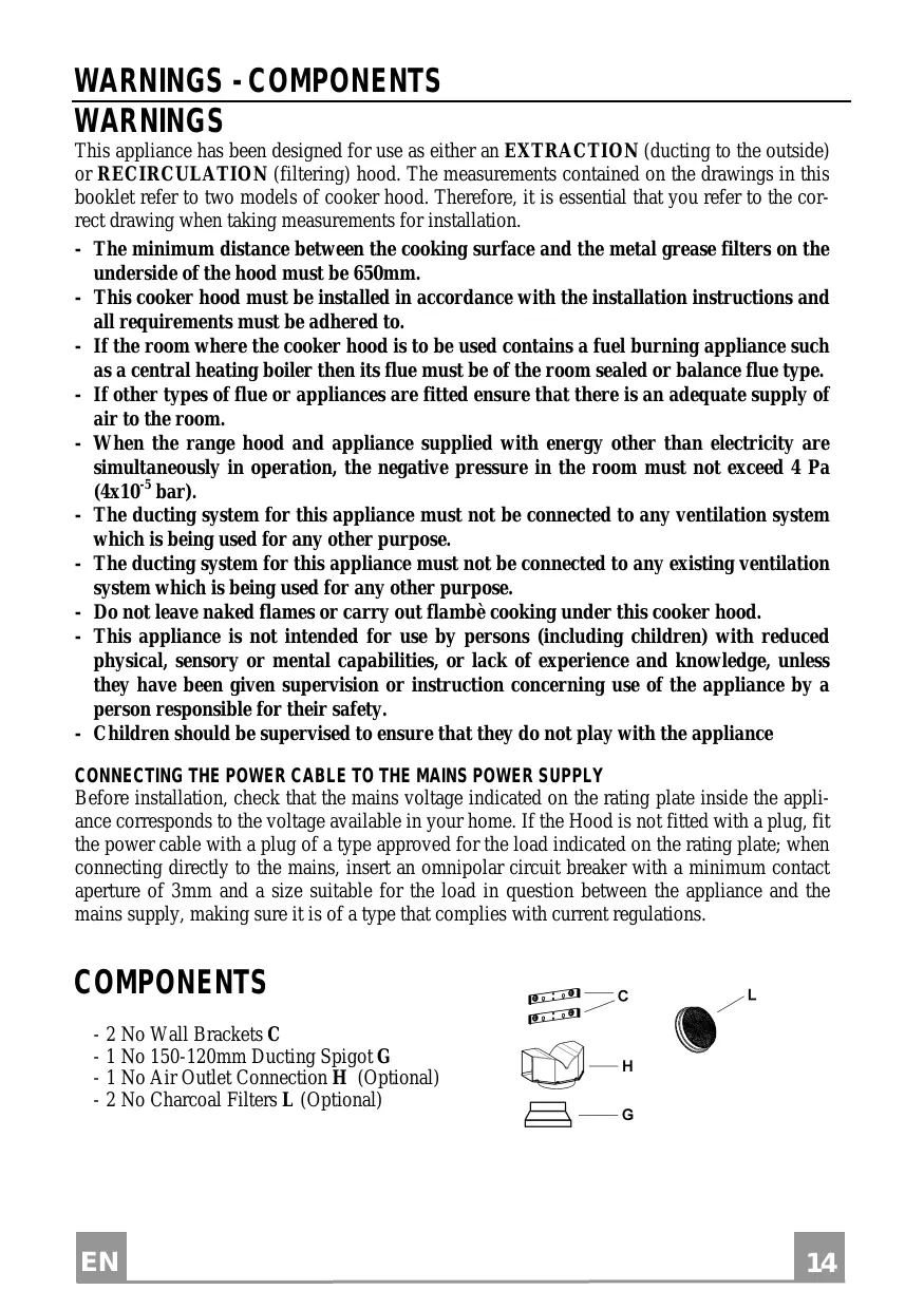
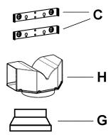
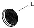
COMPONENTS
- 2 No Wall Brackets C
- 1 No 150-120mm Ducting Spigot G
- 1 No Air Outlet Connection H (Optional)
- 2 No Charcoal Filters L (Optional)
The cooker hood must be installed centrally over a cooking appliance. The minimum distance between the cooking surface and the metal grease filters on the underside of the hood must be at least 650mm .
To install the hood proceed as follows:
1) Drill six 8mm diameter holes at X1-X2-J and insert the plastic rawl plugs supplied as illustrated in fig. 2 ensuring the brackets are fitted as shown in the blow up.
2) Secure the two brackets C to the wall inserting two of the screws supplied through the two holes on line X1-X2 as illustrated in fig. 2.
3) Slide the canopy down the wall to locate the key hole over the washer then secure the canopy to the wall by inserting two of the screws supplied through the two outer holes in the rim of the canopy J1 and J2 as illustrated in fig. 3.
4) EXTRACTION OR RECIRCULATION INSTALLATION:
- EXTRACTION (DUCTED)
When installing the ducted version, connect the hood to the chimney using either a flexible or rigid pipe 150 or 120mm , the choice of which is left to the installer.
- To install a 120 mm air exhaust connection,insert the reducer flange 9 on the hood body outlet.
Fix the pipe in position using sufficient pipe clamps (not supplied). - Remove any activated charcoal filters.
- RECIRCULATION (FILTERED)
- When the hood is fitted in the recirculation mode the Air Outlet Connection H should be fitted as illustrated in fig. 6.
- Fit the (optional) charcoal filters by repeating the following operation on each side of the motor housing. Place the two key hole slots in the filter L and turn the filter clockwise to lock the filter in position as illustrated in fig. 7.
WARNING: It is a possible fire hazard if the metal grease filters are not cleaned and the charcoal filters replaced regularly.
Fitting The Chimney
To fit the upper chimney A , place the top edge of the chimney over the bracket C as illustrated in fig. 8 and secure the chimney using two of the 2.9mm self tapping screws provided.
The distance H in the height between the fixing holes X1 and X2 is determined by the height of the upper chimney A .
To fit the lower chimney B , apply slight force to the two rear edges to increase the width of the aperture, then sleeve the chimney B over the chimney A as illustrated in fig. 9.
USE
The cooker hood functions are controlled by a series of slider or push button switches mounted on the front of the hood and control the worktop lighting and fan motor speeds. This cooker hood will not remove steam.
1)SLIDER SWITCHES
- A switch controls the wotktop lighting - ON/OFF.
- A switch controls the fan speeds - OFF/ON-1-2-3.
- The red neon lamp illuminates when the motor is switched ON.
2)PUSH BUTTON SWITCHES
- A switch controls the worktop lighting - ON/OFF.
- A button switches the motor OFF/ON at the low speed setting.
- A button switches the motor to the medium speed setting.
- A button switches the motor to the high speed setting.
- The red neon lamp illuminates when the motor is switched ON.
3) SPEED SETTINGS
- 1/Low should be selected when simmering or when using only one pan.
- 2/Medium should be selected for cooking when using up to four pans.
- 3/High should be selected when frying or cooking food with a strong odour.
MAINTENANCE
N.B. Before carrying out any kind of maintenance, cleaning or replacing lamps, disconnect the hood from the mains supply.
1. Lighting
Comprises two 40W bulbs. To replace the bulbs, proceed as follows (fig.10): Remove one of the pins at the sides of the lamp cover. Slide the glass towards the side from which the pin has been removed until the opposite edge has been freed, then pull gently downwards. Replace the bulbs and fit the glass again by repeating the above operations in reverse order.
2. Filters
- The metal grease filter should be cleaned every two months or more frequently if the hood is used consistently and can be cleaned in a dishwasher or by hand using a mild detergent or liquid soap. When replacing, ensure that they are dry.
- The charcoal filter cannot be washed and should be replaced at least every 2 months or more frequently if the hood is used consistently.
3. Cleaning
When cleaning the hood, it is recommended to use a damp cloth and mild liquid household cleaner. Never use abrasive cleaning materials.
IMPORTANT: When using a gas hob in connection with the cooker hood never leave the burners of the hob uncovered while the hood is in use or when the pans have been removed. It is very important to follow all instructions for cleaning the hood and filters. There could be a possible fire hazard if the filters are not replaced according to these instructions.
ATTENTION: The manufacturer declines all responsibility for any damage or injury caused as a result of not following the instructions for installation, for maintenance and replacement times of filters indicated (in order to avoid a possible risk of fire when the filters are saturated with grease).
HINWEISE
UMLUFTBETRIEB (OPTION)
TEXHnueCKOE OBCJIyXKIBAHNE
BHIMAHHE!IpeKJTeeMBbIIIOJIHHTBJIIO6BJeOIEpaUHHIOTexo6cJyKJBaHHIO,peMOHTY HIN3aMeHeJIAMIOueK,HEo6XoHMOOTKJIIOuHTBIIpH6OpOTJIEKtpHuYeCKoCetH.
1.OcbeHHeHne
Дя Oсвеценя пeусмтpeно ДBE ЛAMIOЧК MОИHOCTBIO NO 40ВТ.Дя ИХ 3amehы cIeJyET BbIIOJIHNtB OIIHCaHHbE HnKe DeiCtBnR (Pnc.10).
BbHytb OINH H3 IIIbIpei c 60KOBoi CTOpHO b IlafoHa. CdbHytb CTekJIO B CTOpOHy 6e3 IIIbIpy IOOCBO6oKJDeHNII pOTHBOIOJIOXHO KOHua, 3aTeM NtOJHYb CJERKa KHN3y. 3aMeHHb JAMIOUOKn H yCTaHOBHTb CTekJIO, BBIOJIHHB Yka3aHHbIe JeIcTBnB B o6paTHOHIOCJIeIOBAteJIbHOCTH.
2. _HIIbTpbl
Heo6xoJHMOIOCTaTOUHOuACTO(cyETOMpeKHMHaHCIOJIb3OBAHnBbITgKKH),HO He pe-Ke pa3a B 2 MecIua,CHHMATbMetaJIINueCKHe HJIbtpbI HMbITbHXBTeJIIOI MbJIbHOI BOIEHJNKe HEIOCPeIDCTBeHHBO INOCyIDOMoeHoiMaIIHHe.IIOcJIe 3TOrOΦHJIbTpBI Heo6XoJHMO BbICYIIIb H yCTaHOBHTb Ha CBOE MeCTo (yTOJIbHbIEΦHJIbTpBI HNKORJa He MOIOTc;HX CJJeDyET MeHHTb KaKJBle 2 MecIua).
3.Чнстka
IIJI YIcCTKN BHEIIHHX IOBepxHOCTeB BYITJKHNIOJIb3OBAtbcM MIRKOJ TKAHBIO CO CINrTOM HJIN IpyTHMN IIOJXODIAHMM cpeIcTBAMN, HMEIOIHMMcB IIpoJaKe. He CJeIyET IOJIb3oBAtbc a6pa3HBHbIMn COCTaBMn.
BHIMAHHE! HaJIHne OTKpbIrTO OR Hn IpeIcTAbJrEOT OAnacHOCTb IJIa NJIbTPOB, IO-3OMy He peKomeHdyETcOCTabJIrTB rOpJIky BKJIIOHeHHo8 6e3 yCTaHOBJeHHoCBepxu IocUdb. Heo6xoJIMMo BblIOJIHrTB OIEpaUNI IO YNCTKe BblTJXKNI h JINbTPOB, a TAKKe IepHOJInueckyU 3aMeHy IocJIeIHHX, CJIeJy HAIIHM IHCTpyKIIHN M c TEM, YTO6bI H36eKaTb OIAChOCTH IIOKapa.
BHIMAHHE!ΦHpMa-H3rOToBHTeJIb He Hecet OTBcETBeHHocTH 3a BO3MOKHBn yIep6, BO3HNKIIIN B pe3yJIbTaTe HeIOCTaTOUHOrO yXoJa 3a KHPOBbIM ΦHJbTpOM (MoKaKJIbE IBa MeCua), HeBbIIOJIHeHn 3aMeHbI yTOJIbHOro ΦHJbTpA n HecO6JIIODeHn OINCaHHbIX BbIIE NHCtpyKII IN MOHTaKy I IOKJIIOUeHHIO K 3JIeKTPuYeCKoI cETN.
UYARILAR
The symbol on the product or on its packaging indicates that this product may not be treated as household waste. Instead it shall be handed over to the applicable collection point for the recycling of electrical and electronic equipment. By ensuring this product is disposed of correctly, you will help prevent potential negative consequences for the environment and human health, which could otherwise be caused by inappropriate waste handling of this product. For more detailed information about recycling of this product, please contact your local city office, your household waste disposal service or the shop where you purchased the product.
- Instructions Manual INDEX
- CONNECTING THE POWER CABLE TO THE MAINS POWER SUPPLY
- COMPONENTS
- - EXTRACTION (DUCTED)
- - RECIRCULATION (FILTERED)
- Fitting The Chimney
- USE
- 1)SLIDER SWITCHES
- 2)PUSH BUTTON SWITCHES
- 3) SPEED SETTINGS
- MAINTENANCE
- Lighting
- Filters
- Cleaning
- HINWEISE
- UMLUFTBETRIEB (OPTION)
- TEXHnueCKOE OBCJIyXKIBAHNE
- 1.OcbeHHeHne
- _HIIbTpbl
- 3.Чнстka
- UYARILAR
Brand : BEKO
Model : CWB 6441
Category : Cooker