
EX RT 7 3:1 Network - Uninterruptible power supply EATON - Free user manual and instructions
Find the device manual for free EX RT 7 3:1 Network EATON in PDF.


| Product type | Uninterruptible Power Supply (UPS) online double conversion |
| Brand | Eaton |
| Model | EX RT 7 3:1 Network |
| Apparent power | 7000 VA |
| Active power | 6300 W |
| Topology | Double conversion (VFI-SS-111) |
| Input | Three-phase (3 phases + neutral) |
| Output | Single-phase (phase + neutral) |
| Output waveform | Pure sine wave |
| Internal batteries | Yes, hot-swappable |
| Typical runtime (full load) | Approximately 7 minutes |
| Network communication | Integrated network card (SNMP/Web) |
| Display | Backlit LCD screen |
| Dimensions (W x D x H) | 440 x 680 x 130 mm (3U rack format) |
| Weight | Approximately 60 kg |
| Operating temperature | 0 °C to 40 °C |
| Relative humidity | 0% to 95% (non-condensing) |
| Noise level at 1 m | ≤ 50 dB(A) |
| Maintenance and cleaning | Dust off ventilation grilles with a dry cloth; do not use liquids |
| Safety | Emergency power off (EPO); mandatory grounding |
| Spare parts available | Batteries, fans, communication cards |
| Repairability | Modules replaceable by qualified technician |
Frequently Asked Questions - EX RT 7 3:1 Network EATON
User questions about EX RT 7 3:1 Network EATON
0 question about this device. Answer the ones you know or ask your own.
Ask a new question about this device
Download the instructions for your Uninterruptible power supply in PDF format for free! Find your manual EX RT 7 3:1 Network - EATON and take your electronic device back in hand. On this page are published all the documents necessary for the use of your device. EX RT 7 3:1 Network by EATON.
USER MANUAL EX RT 7 3:1 Network EATON
EX RT 5 3:1
EX RT 7 3:1
EX RT 11 3:1
Installation and user manual
English
Français
Deutsch
Italiano
Español
Nederlands
EX RT 5 3:1
EX RT 7 3:1
EX RT 11 3:1

Installation and user manual
Introduction
Thank you for selecting an EATON product to protect your equipment.
The EX RT range has been designed with the utmost care.
We recommend that you take the time to read this manual to take full advantage of the many features of your UPS.
Warning: this is a class A UPS product. In a domestic environment, this product may cause radio interference, in which case, the user may be required to take additional measures.
If the device must be installed in overvoltage category III or IV environments, additional upstream overvoltage protection must be provided for.
To discover the entire range of EATON products and the options available for the EX RT range, we invite you to visit our web site at www.eaton.com or contact your EATON representative.
Environmental protection
EATON cares about the environmental impact of its products and has therefore implemented an eco-design process for the entire life cycle of the EX RT product: design, usage and recycling.
Using this document
Information may be found primarily by checking:
the contents, ●
the index. ●
Icons


Important instructions that must always be followed.
Information, tips, help.
Visual indication.
Action.
Audible alarm.
In the illustrations on the following pages, the symbols below are used:
LED off.
LED on.
LED ashing.

1. Presentation
1.1 Standard con gurations 5
Tower configuration 5
Rack configuration 5
1.2 Rear panels 6
Power module EX RT 5/7/11 6
Battery module EX RT EXB 7/11 6
1.3 Display and control panel 7
1.4 Options 7
Rack mounting kits 7
Transformer for galvanic isolation or earthing arrangement change 8
Battery extensions for UPS backup times up to 60 minutes 9
CLA module (Long backup time charger) for backup times from 2 to 8 hours .....9
Modules integration system 10
Battery module with Remote Emergency Power Off function (REPO) 10
Battery extension cable (1,8 m / 6 ft) 10
2. Installation
2.1 Unpacking and parts check 11
Power module 11
Battery module 11
2.2 Installation in tower con guration 12
2.3 Installation in rack con guration 13
Adjustment of the orientation of the logo and control panels ....13
Battery module rack mounting (optional rail required) 13
Power or battery module rack mounting (optional rail required) 14
2.4 Communication ports 16
Connection to the RS232 communication port 16
Connection to the communications port by relays 16
Remote Power Off 17
Remote Power Off communication port 17
Installation of communication cards (optional, standard with the Network Pack version) 17
2.5 Installation depending on the system earthing arrangement (SEA) 18
UPS with common Normal and Bypass AC inputs 18
UPS with separate Normal and Bypass AC inputs ....18
UPS with separate Normal and Bypass AC inputs, supplied by separate sources....19
Frequency converter (without Bypass AC input) 19
Hot standby 19
2.6 Required protective devices and cable cross-sections 20
Recommended upstream protection 20
Recommended downstream protection 20
Required cable cross-section 20
2.7 Connections of input/output power cables 21
UPS with common Normal and Bypass AC sources 21
UPS with separate Normal and Bypass AC sources 22
Frequency converter 23
Connection of battery cables 24
Connection of galvanic isolation transformer 24
Connection of CLA module 25
Contents
3. Operation
3.1 Initial start up 26
Accessing personalisation with front panel buttons 26
Access to the personalisation through external software 27
3.2 Final start up sequence 27
3.3 Operating modes 28
Normal (double conversion) mode 28 Eco mode 28
3.4 Operation on battery power 29
Transfer to battery power 29
Threshold for the low-battery warning 29
End of backup time 29
3.5 Return of Normal AC source 29
3.6 Shut down 30
4. Maintenance
4.1 Troubleshooting 31
4.2 Hot-swapping the power module 32
Disconnecting the power module .... 32 Reconnecting the power module .... 33
4.3 Hot-swapping the battery module 33
Disconnecting the battery module .... 33 Reconnecting the battery module .... 33
4.4 Training center 34
5. Appendices
5.1 Technical speci cations 35
Electrical characteristics....35
Thermal characteristics 38
5.2 Glossary 38
1. Presentation
1.1 Standard con gurations
Tower con guration

Power module (EX RT 5/7/11)
| Dimensions in mm/ inches (H x W x D) | |
| EX RT 5EX RT 7EX RT 11EX RT EXB 7EX RT EXB 11 | 444 x 131 x 635 |
| Weight in kg/lbs | |
| EX RT 5EX RT 7 | 22.5 |
| EX RT 11 27.5 | |
| EX RT EXB 7 64.5 | |
| EX RT EXB 11 68.5 |
Battery module (EX RT EXB 7/11)
Rack con guration
Power module (EX RT 5/7/11)

| Dimensions in mm/ inches (H x W x D) | |
| EX RT 5EX RT 7EX RT 11EX RT EXB 7EX RT EXB 11 | 131 (3U) x 444 x 635 |
| Weight in kg/lbs | |
| EX RT 5EX RT 7 | 22.5 |
| EX RT 11 27.5 | |
| EX RT EXB 7 64.5 | |
| EX RT EXB 11 68.5 |
Battery module (EX RT EXB 7/11)
1. Presentation
1.2 Rear panels
Power module EX RT 5/7/11

① Slot for communication cards.
② Communication port by relays.
③ Remote Emergency Power Off communication port (REPO).
④ Connectors for automatic detection of battery module(s).
⑤ RS232 communications port.
⑥ Battery module connectors (to the UPS or to other battery modules).
⑦ Manual Bypass switch.
⑧ Output terminal block.
⑨ Normal AC source circuit-breaker.
⑩ Normal AC source terminal block.
⑪ Bypass AC source terminal block.
Battery module EX RT EXB 7/11

④ Connectors for automatic detection of battery module(s).
⑥ Battery module connectors (to the UPS or to other battery modules).
⑫ Battery circuit breaker.
1. Presentation
1.3 Display and control panel


⑬ Load protected LED.
⑭ Operation on battery LED.
⑮ Operation on bypass LED.
⑯ Fault LED.
⑰ Alphanumeric display.
⑱ UPS OFF button.
⑲⑳Function buttons (scroll up / scroll down).
②1 UPS ON button (or function button in personalisation mode).
1.4 Options
Rack mounting kits
Telescopic rails for Power module mounting in 19" enclosure with mounting hardware (Part number 68001)
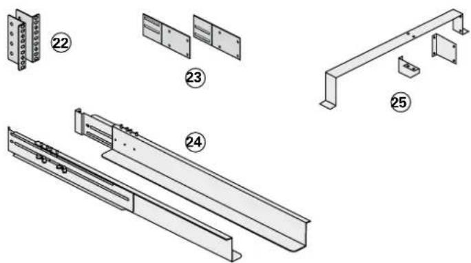
22 Ear hangup.
②3 Rear bracket system for transportation.
24 Telescopic rails, 639 mm to 1005 mm length (27.36" to 39.96").
25 Input/Output box bracket system.
Telescopic rails for Battery module mounting in 19" enclosure with mounting hardware (Part number 68002)
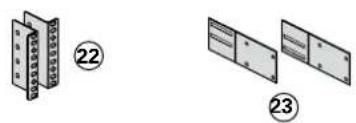
22 Ear hangup.
②3 Rear bracket system for transportation.
24 Telescopic rails, 639 mm to 1005 mm length (27.36" to 39.96").

1. Presentation
Transformer for galvanic isolation or earthing arrangement change (Part number 68003)
This module is necessary either when a downstream neutral system from the UPS upstream is required, or when a different power source connects the automatic bypass for higher availability.

Example of EX RT transformer connected upstream for EX RT galvanic isolation

Battery module (EX RT EXB)
Power module (EX RT 5/7/11)
Transformer module (EX RT)
Normal AC input
UPS output to load
Bypass AC input
1. Presentation
Battery extensions for UPS backup times up to 60 minutes (at full load)
EX RT offers a standard backup time of 5/9 minutes at full load.
To increase backup time, it is possible to connect EX RT EXB 7/11 modules to the UPSs.
Battery extensions for EX RT 5, EX RT 7 or EX RT 11
![graph LR A["EX RT 5/7 + EX RT EXB 7 RT / EX RT 11 + EX RTEXB 11"] --> B["+"] B --> C["EX RT EXB 7 / EX RT EXB 11"] C --> D["+"] D --> E["EX RT EXB 7 / EX RT EXB 11"] E --> F["+"] F --> G["EX RT EXB 7 / EX RT EXB 11"] G --> H["+"] H --> I["EX RT EXB 7 / EX RT EXB 11"] I --> J["+"] J --> K["EX RT EXB…](/content/2026/06/1292976/images/c4a73d965cecb3279638c854bf790da509977aacdc35b45dadd753ac196b560e.jpg)
CLA module (Long backup time charger) for backup times from 2 to 8 hours (Part number 68004)
Very long backup times, from 2 to 8 hours at full load, require a EX RT CLA module.


| Battery backup time | Recommended batteries for: | ||
| EX RT 5 EX RT 7 EX RT 11 | |||
| 2 hours | 50 Ah 65 Ah 100 Ah | ||
| 4 hours | 100 Ah 130 Ah 200 Ah | ||
| 8 hours | 200 Ah 260 Ah 400 Ah | ||
Total battery voltage : 240 V DC (20 x 12V DC).
The battery capacity must be set within the UPS (5 Ah increment possible, see UPS Personalisation section).
1. Presentation
Modules integration system (Part number 68005)
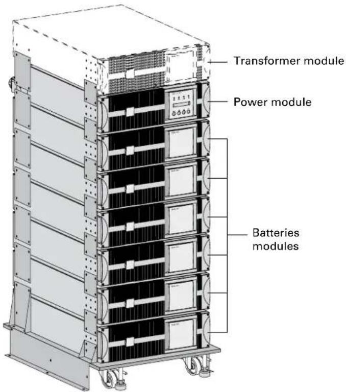
Modules integration system for extended backup time con gurations to conveniently stack and secure up to 8 modules on the same cart (swivel wheels with brakes, leveling feet, seismic side panels, plates to lock modules and screws included).
Battery module with Remote Emergency Power Off function (REPO)

Battery extension cable (1,8 m / 6 ft, Part number 68006)
This extended battery cable will be used instead of the standard battery cable when battery modules are distant from each other (located in two different enclosures, for instance).
2. Installation
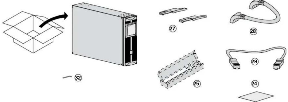
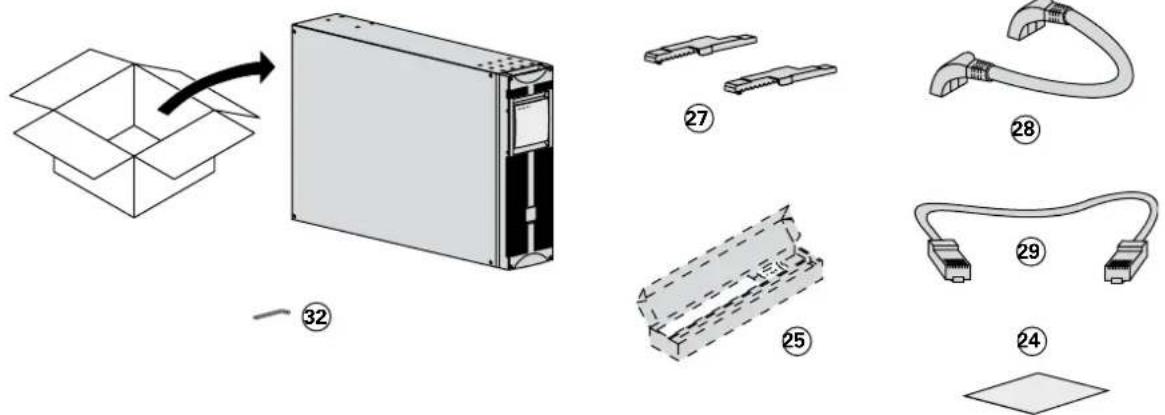
2.1 Unpacking and parts check
Power module

Battery module

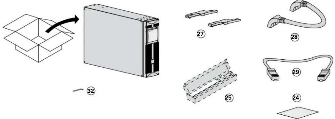
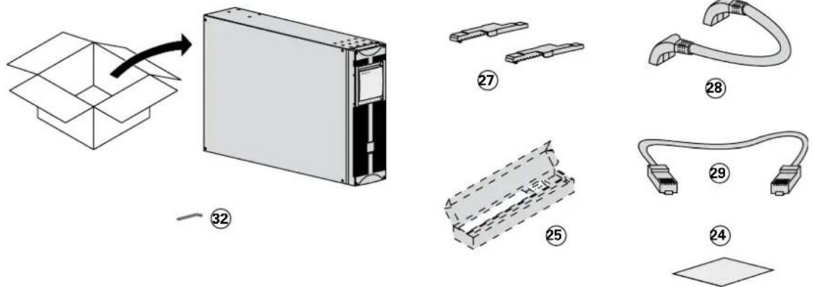
22 Two sets of tower stands.
23 RS232 communications cable.
24 Product documentation.
25 Telescopic rails for rack enclosure with mounting hardware (optional, or standard with Network Pack version).
26 Solution-Pac power management suite CD-ROM.
27 Tower stand expanders.
28 Battery cable.
29 Battery communication cable.
③0 Input/Output junction box (with 11 insulated ferrules).
③1 Network Management card (optional, or standard in Network Pack version).
32 Bezel screw driver.

Packaging must be destroyed according to waste management standards. Recycling icons are displayed for easy selection.
A dangerous voltage is present inside the power module and the battery module. Any operations to be carried out on these modules must be done so by qualified staff.
2. Installation
2.2 Installation in tower con guration

Use the tower stand template provided with the battery module.


Follow steps 1 to 4 to adjust the tower stands for the upright position.

Always keep 150 mm free space behind the UPS rear panel.
The distance between the tower stands should be 450 mm.
2. Installation
2.3 Installation in rack con guration
We recommend to mount the battery module first, then mount the power module above the battery
Adjustment of the orientation of the logo and control panels

![graph TD A["Server Unit 1"] --> B["Component 1: Input Device"] A --> C["Component 2: Input Device"] A --> D["Component 3: Input Device"] A --> E["Component 4: Control Panel"] A --> F["Component 5: Output Module"] A --> G["Component 6: Output Module"]](/content/2026/06/1292976/images/9af8655821a40621477932f7a09b1defaacce460c336941207e93a32cd3869a9.jpg)
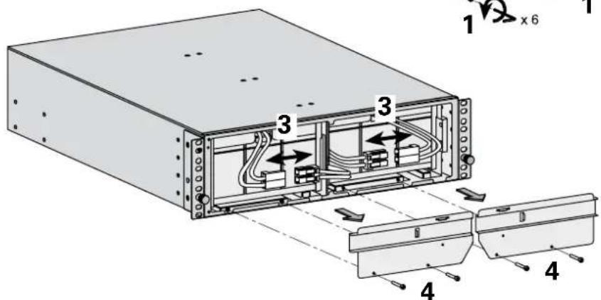
Battery module rack mounting (optional rails required, part number: 68002)

The battery module is very heavy. To ease its rack integration, we strongly recommend to remove the battery trays as explained below:


2. Installation

Power or battery module rack mounting (optional rails required, part number: 68001)

Follow steps 1 to 4 for rack mounting the UPS onto the rails.


The rails and the necessary mounting hardware are supplied by EATON.
Note for step 1: it is possible to adjust the position of both front mounting ears.
2. Installation
Rear bracket system (included with rail kits, part numbers 68001 and 68002)

To be used if you need to move the rack enclosure with UPS already rack-mounted inside.

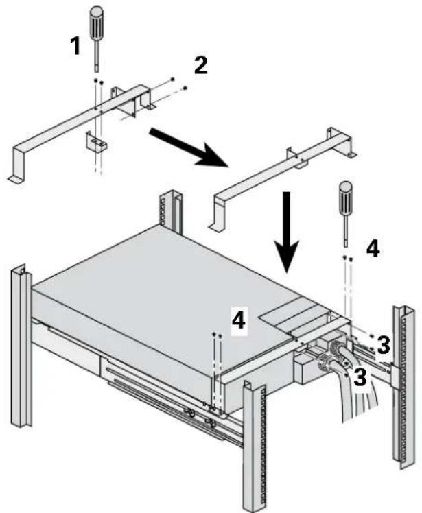
Input/output junction box bracket system (included with power module rail kit, part number 68001)

This bracket will maintain the Input/Output box at the rear of the rack enclosure when hot-swapping the power module.
It will then be easier to slide the replacement module into the connectors of the Input/Output box.
2. Installation
2.4 Communication ports
EX RT provides 3 communication methods that can be used simultaneously:
The COM port provides RS232 communications using EATON SHUT protocol. Compatible with most power management software applications available into the enclosed Solution Pac CD-Rom.
- The output contact port is used for basic signaling or for protection of IT systems like IBM iSeries (formerly AS400) and more.
- The slot is compatible with any EATON communication card (check www.eaton.com web site for the complete list of compatible cards).
Connection to the RS232 communication port

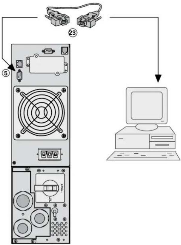
1 - Connect the RS 232 23 communications cable to the serial port on the computer.
2 - Connect the other end of the communications cable ②3 to the RS 232 ⑤ communications port on the UPS.
The UPS can now communicate with various EATON power management application software. Please note that the con guration software is included with Personal Solution Pac for Windows.
Connection to the communication port by relays ②

Pin 3: Remote Power Off signal (5 to 27 V DC, 10 mA max), ●
Pin 4: Operation on mains (not on battery), ●
Pin 5: User common, ●
Pin 6: Operation on automatic by-pass, ●
Pin 7: Low battery, ●
Pin 8: Load protected, ●
Pin 9: Operation on battery.
n.o.: contact normally open.
n.c.: contact normally closed.
When the status is active, the contact between the common (Pin 5) and the relevant information pin is closed.
Output relays speci cations
Voltage: 48 V DC max, ●
Current: 2 A max, ●
Power: 62,5 VA, 30 W. ●
Example: for 48 V DC, Imax = 625 mA
2. Installation
Remote Power Off
Installation of a Remote power off function must be carried out in compliance with applicable regulations.
In order to fully de-energize devices and EX RT with an RPO port, it is necessary :
- To use a two-position switch (Normally Open or Closed contact should be held more than 1 second to be taken into account).
- To use battery cabinet(s) EX RT EXB EPO.
- To connect to this RPO switch a device that allows to trip all breaker(s) located upstream (1) AC NORMAL and AC BY PASS as well as downstream (2) the EX RT. This can be achieved through by means of a shunt trip.
(1) If not, the output devices will remain powered through the AC BY PASS if RPO switch has been loosened.
(2) If not, the output devices will remain powered several seconds after the RPO activation.
Remote Power Off communication port ③
Used in conjunction with the optional EPO battery module, this port enables total isolation of all power sources connected to the UPS in case of emergency (the cable is not provided).
Remote power off contact normally open
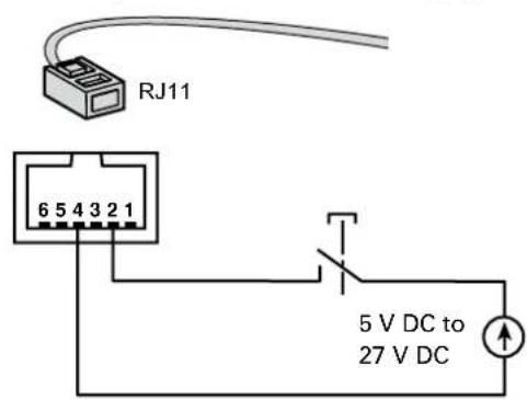
Remote power off contact normally closed

Signal: ●
- activation voltage: 5 V DC to 27 V DC.
- current: 10 mA max.
Installation of communication cards (optional, standard with the Network Pack version)


Communication card.
It is not necessary to shut down the UPS to install the communication card:
1 - Remove the slot cover secured by two screws.
2 - Insert the card ① into the slot.
3 - Secure the card with both screws.
2. Installation
2.5 Installation depending on the system earthing arrangement (SEA)

EX RT must be fed from a 3-phase source with neutral.
UPS with common Normal and Bypass AC inputs
![graph LR A["Main low-voltage switchboard (MLVS)"] --> B["Bypass AC Normal AC"] B --> C["Switch 8"] B --> D["Switch 10"] C --> E["Load"] D --> E style A fill:#f9f,stroke:#333 style E fill:#ccf,stroke:#333](/content/2026/06/1292976/images/6baa95f040339797b5297bed0690ec99acac8f3785e0ebd8aa8460c33f7e3eff.jpg)
(*): The transformer is not necessary if:
Normal and Bypass AC inputs are connected to the same source, ●
and wires cross sections and wires lengths on Normal and Bypass inputs are identical, ●
● and upstream protection is provided by only one switch with RCD (residual current device) for Normal and Bypass inputs.
UPS with separate Normal and Bypass AC inputs, supplied by separate sources
![graph TD subgraph_MLVS1["MLVS 1"] A1["Switch"] --> B1["Bypass AC 11"] B1 --> C1["Diode symbol"] C1 --> D1["&"] D1 --> E1["load"] end subgraph_MLVS2["MLVS 2"] A2["Switch"] --> B2["Power Circle Normal AC 10"] B2 --> C2["&"] C2 --> D2["&"] D2 --> E2["load"] end subgraph_MLVS1["MLVS 1"] A3["Switch"] -->…](/content/2026/06/1292976/images/8b068dfafefaa97fead06f631170624c629795654f189af7ac345036765ee737.jpg)
Change in SEA between upstream and downstream or galvanic isolation required
![graph LR A["MLVS 1"] --> B["Bypass AC"] C["MLVS 2"] --> D["Normal AC"] B --> E["11"] D --> F["10"] E --> G["~"] F --> H["~"] G --> I["8"] H --> J["load"]](/content/2026/06/1292976/images/3569cea5e8d26ec8625d32c633a726935cbaa621265a0bae09b2dfd9767745c2.jpg)
Frequency converter (without Bypass AC input)
Con guration used when the frequency of the application differs from the Mains (Example: marine requirements).
![graph LR A["Main low-voltage switchboard (MLVS)"] --> B["Normal AC"] B --> C["Component 10"] C --> D["Component 8"] D --> E["load"]](/content/2026/06/1292976/images/4616ef7f004116abf410a10f30f0db5adcf34548fe635e77b1bfe9df46f8ac98.jpg)
Hot stand by
Con guration used to provide full redundancy (N+1) to critical loads.
![graph TD A["Main low-voltage switchboard (MLVS)"] --> B["Main low-voltage switchboard (MLVS)"] B --> C1["11"] B --> C2["10"] B --> C3["8"] C1 --> D1["Bypass AC"] C2 --> D2["Normal AC"] C3 --> D3["Normal AC"] D1 --> E1["Diode Symbol"] D2 --> E2["Diode Symbol"] D3 --> E3["Diode Symbol"] E1 --> F["Load…](/content/2026/06/1292976/images/2df7e380cc91d188130b1f841ec509b269436ae14f5cd568ca1d800c2a840ae6.jpg)
2. Installation
2.6 Required protective devices and cable cross-sections
Recommended upstream protection
| UPS power rating | Common AC inputsUpstream circuit-breaker Normal / Bypass AC sources | Separate AC inputs | |
| Upstream circuit-breaker Normal AC source | Upstream circuit-breaker Bypass AC source | ||
| 5 kVA | D curve - 40 A C curve - | 32 A D curve - 40 A | |
| 7 kVA | D curve - 40 A C curve - | 32 A D curve - 40 A | |
| 11 kVA | D curve - 63 A C curve - | 40 A D curve - 63 A | |

Note: see the simplified diagrams in the appendix for common or separate AC inputs, indicating the positions of the protection devices, the characteristics of the internal UPS fuses and UPS line currents under overload conditions.
Recommended downstream protection
| UPS power rating | Downstream circuit breaker |
| 5 kVA | Z curve - 10 A |
| C curve - 4 A | |
| 7 kVA | Z curve - 10 A |
| C curve - 4 A | |
| 11 kVA | Z curve - 10 A |
| C curve - 6 A |
The indicated protection ensures discrimination for each output circuit downstream of the UPS, whether supplied by the Normal or the Bypass AC source.
If these recommendations are not followed, protection discrimination is not achieved and may result in a potential power interruption to the connected devices.

Note: see the simplified diagrams in the appendix for common or separate AC inputs, indicating the positions of the protection devices, the characteristics of the internal UPS fuses and UPS line currents under overload conditions.
Required cable cross-sections
Terminal-block cable capacity: 10 mm 2 , solid or stranded wire (maximum 13 mm 2 or AWG 6). ● Capacity for earthing conductor: 10 mm 2 , solid or stranded wire (maximum 13 mm 2 or AWG 6). ●
2. Installation
2.7 Connections of input/output power cables
This type of connection must be carried out by qualified electrical personnel. ●
Before carrying out any connection, check that the battery circuit breaker ② and that the upstream protection devices (Normal and Bypass AC sources) are open ("0").
- EX RT UPS always comes from factory with Normal and Bypass AC inputs already connected together, using a bridge.
Use included insulated ferrules with stranded wires. ●
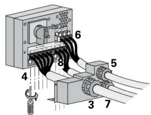
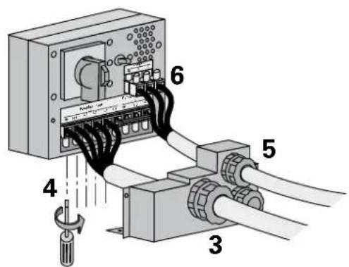
UPS with common Normal and Bypass AC sources


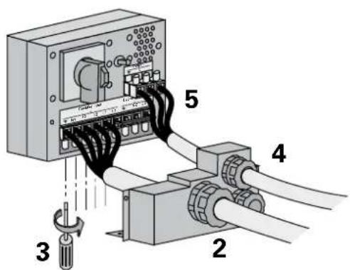
To access the connection terminal blocks, see section 1.2 "Rear panel":
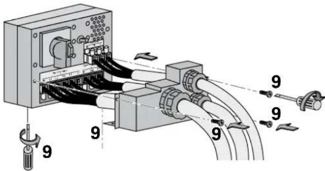
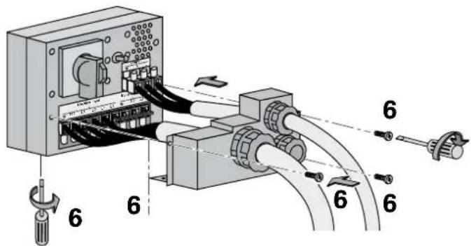
1 - Remove the terminal block cover (5 screws),
2 - Insert the Normal AC cable through the cable gland,
3 - Connect the 5 wires to the Normal AC terminal block,

Always connect the earthing wire first.
4 - Insert the output cable to the load through the output cable gland,
5 - Connect the 3 wires to the output terminal block,
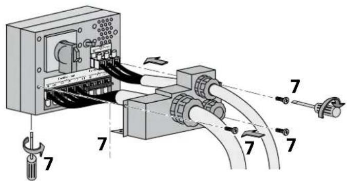
6 - Re t the terminal block cover and tighten the cable glands,
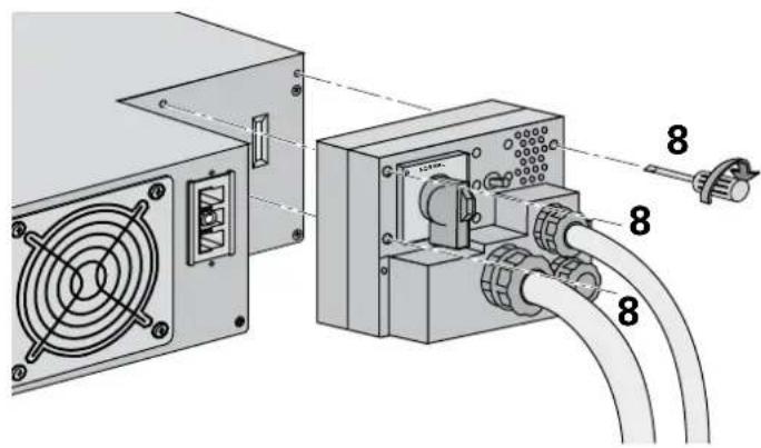
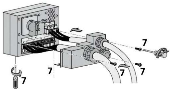
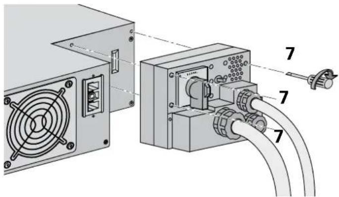
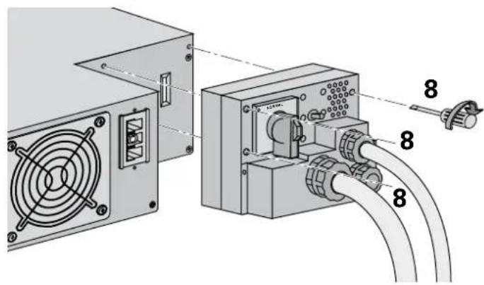
7 - Secure the junction Input/Output box to the rear of the power module by means of the 3 screws.
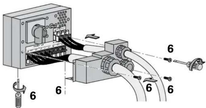

2. Installation
UPS with separate Normal and Bypass AC sources

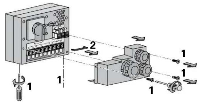
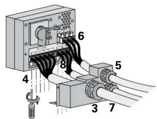
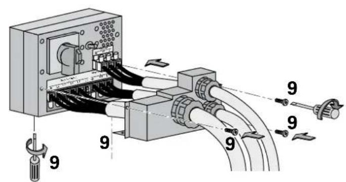

1 - Remove the terminal block cover (5 screws),
2 - Remove the bridge connected between L2 and L1,
3 - Insert the Normal AC cable through the cable gland,
4 - Connect the 5 wires to the Normal AC terminal block,

Always connect the earthing wire first.
5 - Insert the Output cable to the load through the Output cable gland,
6 - Connect the 3 wires to the output terminal block,
7 - Insert the Bypass cable through the cable gland,
8 - Connect the 3 wires to the Bypass AC terminal block,
9 - Re t the terminal block cover and tighten the cable glands,
10 - Secure the junction Input/Output box to the rear of the power module by means of the 3 screws.
2. Installation
Frequency converter

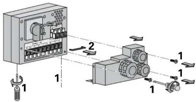
1 - Remove the terminal block cover (5 screws),
2 - Remove the bridge connected between L2 and L1,
3 - Insert the Normal AC cable through the cable gland,
4 - Connect the 5 wires to the Normal AC terminal block,

Always connect the earthing wire first.

5 - Insert the Output cable suppling the load through the Output cable gland,
6 - Connect the 3 wires to output terminal block,

Do not connect anything to the Bypass AC terminal block,
7 - Re t the terminal block cover and tighten the cable glands,
8 - Secure the junction Input/Output box to the rear of the power module by means of the 3 screws.


2. Installation
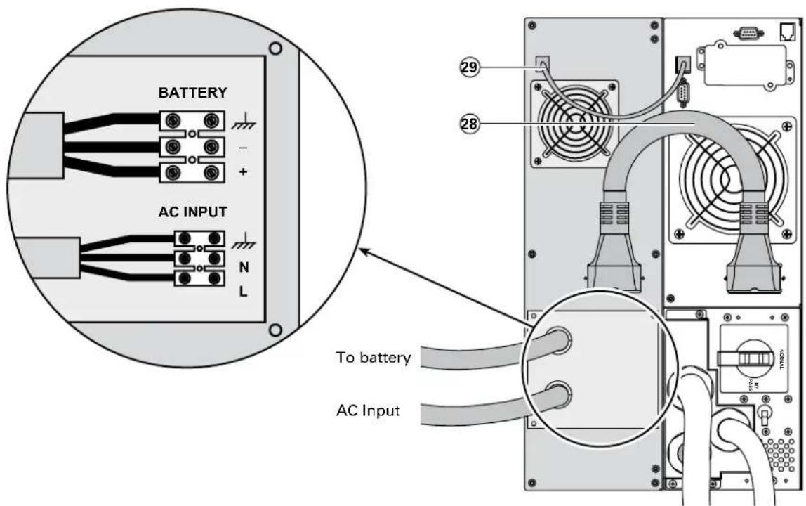
Connection of battery cables


1 - Check that the battery circuit breaker ⑫ is OFF ("0" position),
2 - Connect the battery power cable
28 to the connectors 6 of the power and battery modules,
3 - Connect the battery detection cable
29 to the connectors ④ of the power and battery modules,
Connection of galvanic isolation transformer

- Output cable cross-section (not provided): 10 mm 2 , solid or stranded wire (maximum 13 mm 2 or AWG 6).
- Input cable cross-section (not provided): 10 mm 2 , solid or stranded wire (maximum 13 mm 2 or AWG 6).
2. Installation
Connection of CLA module

Connect the battery cable ③ (provided with the CLA module) between the power module and the CLA module.
Connect the cable (provided with the CLA module) between the power module and the CLA module. Connect the battery:
- cable cross-section (not provided): 10 mm 2 , solid or stranded wire (maximum 13 mm 2 or AWG 6). Use a circuit-breaker (curve B, 50 A) for cable protection. ●
- Connect the input cable of the CLA module to the AC input:
- AC input cable cross-section (not provided) : 2,5 mm 2 . Use a circuit-breaker (curve C, 10 A) for cable protection. ●
3. Operation
3.1 Initial start up


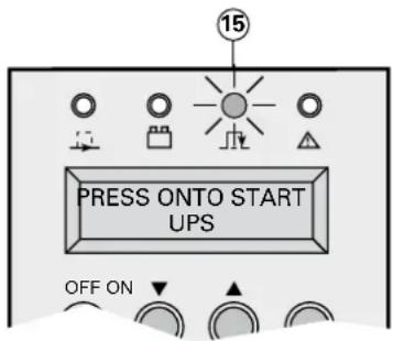
Check that the manual bypass switch ⑦ is on Normal position. Set the normal AC source circuit-breaker ⑨ to the "l" position. Set the battery circuit breaker ⑫ to the "l" position.
The load is powered via the bypass AC source, but not protected by the UPS.
Batteries are recharging, an eight-hour recharge period is necessary to get full backup time.
LED 15 is ON.
UPS personalisation

If speci c settings are required, it is recommended to enter the UPS personnalisation mode at this stage. It is possible to enter this mode through the front panel buttons or the Personal Solution-Pac software for Windows included in the EATON Solution-Pac power management suite CD-ROM.
Accessing personalisation with front panel buttons


Press "scroll up" ① and "scroll down" ② function buttons together for more than 3 seconds.
Press the function button 20 placed under the ENT word to enter the set up mode and follow the LCD messages using the buttons now de ned as select keys.
Local settings
| Function Factory setting Options | ||
| Language | English French, | Spanish, German, Italian. |
| Date / time format | International format (DD-MM-YYYY/HH:MM) | US format (MM-DD-YYYY/HH:MM AM/PM). |
| Date / time change | Time in France MM | DD-YYYY/HH:MM adjustable. |
| Audible alarm | Quick beeps Slow | beeps. |
| Function Factory setting Options Comments | |||
| Output voltage 230 Volts AC | 200/208/220/2 | 40/250 | |
| Frequency converter | Disabled | Enabled | Bypass AC source disabled. |
| Output frequency | Auto ranging | 50/60 Hz | User selectable under frequency converter mode. |
| Eco mode | Disabled | Enabled | See glossary. |
| Hot standby | Disabled | Enabled | N+1 redundancy(See section 2.5 "Hot standby"). |
| Operating mode | Industrial | I/T Network | (*) |
| Transfer on Bypass AC source | If the Bypass AC source is out of tolerances | If the Bypass AC source is inside tolerances | (*) |
| Break time | 10 ms | 10 to 200 ms(by steps of 10 ms) | Break time calibration during load transfer on Bypass AC source out of tolerances. |
| Overload level | 102 % | 50/70 % | |
(*) : - Select "I/T Network" and "AC Bypass within tolerance" for computer loads.
- Select "Industrial" and "AC Bypass out of tolerance" in case of absolute need for service continuity (with potential 10 ms break).
3. Operation
ON/OFF features
| Function Factory setting Options Comments | |||
| Cold start | Disabled | Enabled | Start on battery. |
| Forced reboot | Enabled | Disabled | Enables automatic restart of the system even if normal AC source is restored before the end of the shutdown sequence. |
| Automatic restart | Enabled | Disabled | UPS restarts automatically when normal AC source is restored. |
| Sleep mode | Disabled | Enabled | Automatic shutdown on battery if output load level < 10%. |
| UPS ON/OFF by software | Enabled | Disabled | Enables consideration of shutdown or restart orders from software to be authorized. |
| Function Factory setting Options | Comments | ||
| Battery test | Every week | No test / daily / monthly | |
| Low battery signal | 20 % | 0 to 100 % | 1% increment. |
| Run time choice | UPS reads # of battery modules connected | From 50 to 400 Ah | Requires EX RT CLA if using options (see section 1.4 "Battery extensions"). |
| Battery deep discharge protection | Enabled | Disabled | If disabled, lost of EATON warranty. |
Use EXIT key when set up is completed. ●
● These parameters are only adjustable if UPS is OFF.
Access to the personalisation through external software

- Insert the Solution-Pac CD ROM in your CD drive.
- At the rst Navigator Screen, select "Installation" and follow the instructions to install Personal Solution-Pac for Windows.
If nothing appears, launch startup.exe ●
Then go to "Advanced settings" and "UPS settings".
Please note that the Linux/Unix/MacOS versions of Personal Solution-Pac do not include this feature.
3.2 Final start up sequence

Press the ON button more than 3 seconds. ●
After UPS internal test sequence, the green LED ③ goes on.
During the restart, if the Bypass AC source is out of tolerance, the UPS will generate an output 10 ms calibrated break.
3. Operation
3.3 Operating modes
Normal (double conversion) mode

This is the standard operating mode, set by default in the factory.
Two possible choices.
1 - Normal AC source available:
LED 13 is ON.
The load is protected by the UPS.
Scroll up ⑲ and scroll down ⑳ function buttons allow you to read the UPS measurements (Normal AC source voltage, Bypass AC source voltage, operating mode, battery capacity and UPS Serial Number).
2 - Normal AC source not available:
LED ⑬ ashes.
LED 14 is ON.
The audible alarm sounds intermittently.
The load is supplied by the UPS from battery power.
Do not operate the manual Bypass switch ⑦ when the UPS is in the normal mode.
Eco mode

The main advantage of the Eco mode (see glossary) is that it reduces the consumption of electrical power.
Three possible choices:
1 - Bypass AC source available:
LEDs ⑬ and ⑮ are ON.
The load is supplied in ECO mode.
2 - Bypass AC source not available:
LED 13 is ON.
The audio alarm sounds intermittently.
The load is automatically supplied in Normal mode via the Normal AC input.
3 - Both Normal and Bypass AC sources not available or out of tolerance:
LED 13 is ON.
LED ⑭ is ON.
The audio alarm sounds intermittently.
The load is supplied by the UPS from battery power.
The display indicates the battery remaining backup time.
3. Operation
3.4 Operation on battery power
The load continues to be protected by the UPS when the Normal AC source is not available. Power is supplied by the battery.
Transfer to battery power

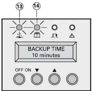
LED 13 is ON.
LED 14 is ON.
The audio alarm beeps every 10 seconds.
The load is supplied by the battery.
The display indicates the battery remaining backup time.
Threshold for the low-battery warning


LED ⑬ is ON.
LED ⑭ ashes.
The audio alarm beeps every 3 seconds.
Low battery warning on display. There is very little remaining battery backup time. Close all applications because UPS automatic shutdown is impending.
End of backup time
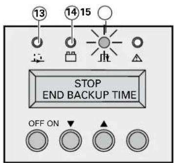
LED ⑬ and ⑭ are OFF.
The audio alarm is stopped.
The load is transferred to the Bypass AC source if available. In this case, the LED 15 is ON.
3.5 Return of Normal AC source
After an outage, the UPS restarts automatically when AC power is restored (unless this function has been disabled via UPS personalisation).
3. Operation
3.6 Shut down

1 - Press the OFF button ⑱ more than 3 seconds.

The load is no longer protected by the UPS. It is powered via the bypass AC source. If the UPS is set in frequency converter mode, the load will not be powered. If the bypass AC source is out of tolerance, the UPS will generate a 10 ms output calibrated break.
2 - Set the battery circuit breaker(s) ⑫ to the "0" position.
3 - Set the Normal AC source circuit-breaker ⑨ to the "0" position.
4 - For a full shutdown of UPS and connected load, the
4.1 Troubleshooting

If any of LEDs 15 or 16 is on, there is an operating anomaly or an alarm. Use "scroll up" or "scroll down" function button to reset the audible alarm.
Troubleshooting not requiring EATON after-sales support:
| Indication Signi cation Correction | ||
| Led 15 is on,the alphanumeric display shows:BAD CONNECTIONREWIRE AC NORMAL | AC source is not connected to the correct terminals. | Rewire correctly the normal AC source. |
| Led 15 is on,the alphanumeric display shows:LOAD LEVELXx kW / XX KVA | Load supplied by bypass AC source. | Push the ON button for more than 3 seconds. |
| Led 15 is on*,the alphanumeric display shows:THERMAL OVERLOAD1XX% | UPS overload. Check the power drawn by the equipment and disconnect any non-priority devices. | |
| Led 16 is on,the alphanumeric display shows:CURRENT OVERLOAD | Short circuit conditions on output devices. | Check if any device is shorted or failed. |
| Audible alarm is on,the alphanumeric display shows:I/O BOX REMOVED | Junction of Input/Output box not correctly screwed. | Check if the junction Input/Output |
(*) : if bypass AC source available.
Troubleshooting requiring EATON after-sales support:
| Indication Signi cation Correction | ||
| Leds 15* and 16are on and audible alarm is on.The alphanumeric display shows: xxx FAULTwww.eaton.com | Internal fault and transfer of load on bypass AC source. | Follow the UPS replacement procedure (see section 4.3).Call the after sales support department. |
| Led 15is on* and audible alarm is on.the alphanumeric display shows:BATTERY FAULT | Battery fault during the battery test. | Follow the battery replacement procedure (see section 4.3).Call the after sales support department. |
| Led 15is on,the alphanumeric display shows:SHUTDOWNSTATIC SW FAILED | Static switch failure. Follow the UPS replacement procedure (see section 4.3).Call the after sales support department. | |
| Audible alarm is on, and the alphanumeric display shows:BATTERY CHECKwww.eaton.com | Batteries may have exceeded there rated life period. Battery capacity is severely reduced. | Call the local after sales support: www.eaton.com, "Contact Us" section**. |
(*): if bypass AC source is available.
(**): to reset this alarm permanently, press both function buttons 19 and 20 for more than 3 seconds and access the LCM Setup menu.
4. Maintenance
4.2 Hot-swapping the power module

This operation can be performed without interrupting the load.
Disconnecting the power module


Stop the UPS with the OFF button ⓤ8 (press more than 3 seconds).
Check if UPS is on bypass AC source: ● led 15 is on (If led 15 is not on, do not turn the manual bypass and call the after sales support department).
Turn the manual bypass switch ⏻ to the BYPASS position.
Switch the battery circuit breaker(s) ② to the "0" position.
Switch the Normal AC source circuit-breaker ⚙ to the "0" position and wait 30 seconds.
Remove the three xing screws to free the junction Input/● Output box.
Disconnect the battery cables 28 and 29 from the power module.

Tower con guration

The power module can be replaced. The connected equipment is powered by the Bypass AC source.
Rack con guration

4. Maintenance
Reconnecting the power module


Secure the Input/Output junction box using the three screws. ●
Reconnect the battery cables ③ and ⑲ to the power module.
Switch the battery circuit breaker(s) ② to the "l" position.
Switch the Normal AC source circuit-breaker Ⓐ to the "I" position.
Turn the manual bypass switch from the BYPASS to the ● NORMAL position.
Check that the led 15 is on.
Follow initial start up sequence (see section 3.1) in order to personalize the UPS.
Push the ON button Ⓜ for more than 3 seconds.
The green led ⑬ is on, and the connected equipment is now protected by the UPS.
4.3 Hot-swapping the battery module
Disconnecting the battery module


Reconnecting the battery module

Switch the battery circuit breaker(s) ☑ to the "0" position.
Disconnect the battery cables 28 and 29 from the power module.
The battery module can be replaced. The connected equipment is powered by the UPS.
It is also possible to replace battery trays instead of battery module.
Contact your nearest after sales support service.
To remove battery trays:
First, switch the battery circuit breaker(s) ⏻ to the "0" position.
See section 2.3 and follow instructions to remove battery ● trays.
Reconnect the battery cables 28 and 29 to the power module.
Switch the battery circuit breaker(s) ② to the "I" position.
To reconnect battery trays:
See section 2.3 and follow the reverse instructions.
When battery module front panel is closed, connect the ● battery cables 28 and 29 to the power module.
Switch the battery circuit breaker(s) ② to the "l" position.
4. Maintenance
4.4 Training Center

To allow you to use EATON products effectively and carry out basic maintenance, we offer a complete range of technical training courses in English and French.
For further information, please visit our website: www.eaton.com
5.1 Technical speci cations
Electrical characteristics
I/T network and industrial operating modes
| Mode Industrial mode I/T network mode | ||
| Overload, and Bypass AC source in tolerance. | Same as I/T network mode, but the UPS does not return to normal mode if overload released. | Load is transferred to Bypass AC source.UPS returns to normal mode if overload released. |
| Overload, and Bypass AC source not in tolerance. | Load is transferred to Bypass AC source with 10 milliseconds output break. The UPS does not return to normal mode if overload released. | The UPS shuts down and load is not transferred to Bypass AC source. |
| Output short circuit and Bypass AC source in tolerance. | Load is transferred to Bypass AC source, the UPS returns to normal mode if the short circuit is released by downstream circuit breaker action (see section 2.6). | The load remains powered by the UPS.The UPS shuts down after 3 minutes if the short circuit remains. |
| Output short circuit and Bypass AC source not in tolerance. | The load is transferred to Bypass AC source with 10 milliseconds output break. The UPS does not return to normal mode if the short circuit is released by downstream circuit breaker action (see section 2.6). | The load remains powered by the UPS. The UPS shuts down after 3 minutes if the short circuit remains. |
Selection of protection devices
UPS unit with common Normal and Bypass AC inputs
![graph LR A["Bypass AC\nNormal AC"] --> B["Upstream circuit breaker\n(not supplied)"] B --> C["10"] C --> D["Normal AC source circuit breaker"] D --> E["Input fuse"] E --> F["~"] F --> G["Output fuse"] G --> H["8"] H --> I["Downstream circuit breaker\n(not supplied)"] C --> J["9"] J --> D style A fil…](/content/2026/06/1292976/images/01f5fdffe828fd869db4a251566bd2181a409c80c5aba19cd00572db51e50891.jpg)
UPS unit with separate Normal and Bypass AC inputs
![graph LR A["Upstream circuit breaker (not supplied)"] --> B["11"] C["Normal AC source circuit breaker"] --> D["10"] E["Input fuse"] --> F["~"] G["Output fuse"] --> H["8"] I["Bypass AC"] --> J["11"] K["Downstream circuit breaker (not supplied)"] --> L["8"] style A fill:#f9f,stroke:#333 style C fill:#…](/content/2026/06/1292976/images/a3e3d178bcf071b89fe0e4052c7ca90aaeb20c4cc0991b660e0934cfa828bfaf.jpg)
When sizing the upstream circuit breakers, the parameters presented below must be taken into account:
Line current values
| UPS power rating | Continuous current at 400/320 Volts and nominal load | Continuous current at 320 Volts and overload = 110 % limited to 2 minutes | Input fuse rating | Output fuse rating |
| 5 kVA 9/10 A | 11 A 25 A 80 A | |||
| 7 kVA 10/11 A | 12 A 25 A 80 A | |||
| 11 kVA 15/19 A | 21 A 30 A 100 A |
Discrimination of upstream/downstream protections mentioned in paragraph 2.6 is achieved for a 30 m cable length and 10 mm 4 cross section.
Circuit breaker capacity must be selected according to the installation, length and cross section of cables.
5. Appendices
Time/current curves for UPS Normal AC source circuit-breaker

Time/current curves for UPS input and output fuses


5. Appendices
UPS Input / output characteristics
| Source Voltage Frequency | ||
| Normal AC source 320 to 465 Volts | AC 40 to 70 Hz | |
| Bypass AC source 187 to 264 Volts | AC* 48 to 52 Hz** | |
| Load output 230 Volts AC (200/208/220/240/250 V are possible values) | 50/60 Hz autoranging (or frequency converter) | |
(*): depends on output voltage setting, can be modified by software.
(**): set to +/- 4% by default, (1,2,4,8 are possible values), can be modi ed by software.
Power supplied as a function of input voltage

Permissible UPS overloads as a function of time

Short-circuit current provided by the UPS in Normal or Batterie mode
EX RT 5 ● : 110 A for 80 ms.
EX RT 7 ● : 110 A for 80 ms.
EX RT 11 ● : 150 A for 80 ms.
EX RT Transformer
| Nominal power | 11 kVA |
| Nominal current | 63 A |
| Input voltage | 160-280 Volts AC |
| Voltage drop | 7 Volts at nominal load |
| Frequency | 50/60 Hz (+/-10 %) |
| Isolation (EN 61558-1-2-4) | 3.75 kV / 5 M ohms |
| Operating temperature | From 0° to +40°C |
| Max. operating rel. humidity | 95 % |
| Derating / altitude | Pn -10 % > 1000 m |
| Dimensions HxWxD (tower) | 444 x 131 x 635 mm |
| Dimensions HxWxD (rack 3U) | 131 x 444 x 635 mm |
| Weight | 86.5 kg |
5. Appendices
EX RT CLA module
AC input voltage: 160-280 Volts AC, ●
Input frequency: 40-70 Hz, ●
●Battery charge current: 6 A DC,
● Recharge time to recover 90% of the rated backup time after discharge at full load:
| Con guration for 2 hours backup time | Con guration for 4 hours backup time | Con guration for 8 hours backup time | |
| EX RT 5 | 5 hours | 12 hours | 20 hours |
| EX RT 7 | 5 hours | 12 hours | 20 hours |
| EX RT 11 | 7 hours | 15 hours | 24 hours |
Thermal characteristics
- The operating temperature is 0 to 40°C (8 hours at 45°C ), however optimum operation is within the +20 to +25°C range.
- Battery backup time is adversely affected by high and low temperatures. It is significantly reduced at temperatures under 10°C . Above 25°C , battery service life is cut in half every 10°C . Above 40°C , battery manufacturers no longer guarantee operation due to the risk of thermal runaway.
- Air enters through the front and exits through the back.
5.2 Glossary
Backup time Time that the connected loads can operate on battery power.
Bypass AC source Source supplying the bypass line. The load can be transferred to the bypass line if an overload occurs on the UPS output, for maintenance or in the event of a malfunction.
ECO mode Operating mode by which the load is supplied directly by the AC source if it is within the tolerances defined by the user. This mode reduces the consumption of electrical power.
Load Devices or systems connected to the UPS output.
Manual bypass AC source. Rotary switch controlled by the user, used to connect the loads directly to the
Transfer of the load to the manual bypass enables UPS maintenance without interrupting the supply of power to the connected loads.
Normal (double conversion) mode
The normal UPS operating mode in which the AC source supplies the UPS which in turn supplies the connected loads (after electronic double conversion).
Normal AC source Normal source of power for the UPS.
Relay contacts Contacts supplying information to the user in the form of signals.
UPS Uninterruptible Power Supply.
EX RT 5 3:1
EX RT 7 3:1
EX RT 11 3:1

1.1 Positions standards ....5 Position tour ....5 Position rack ....5
1.2 Faces arrières ....6 Module de puissance EX RT 5/7/11 ....6 Module batterie EX RT EXB 7/11 ....6
Mode normal (double conversion) 28
Mode Eco 28
1.1 Positions standards
Position tour
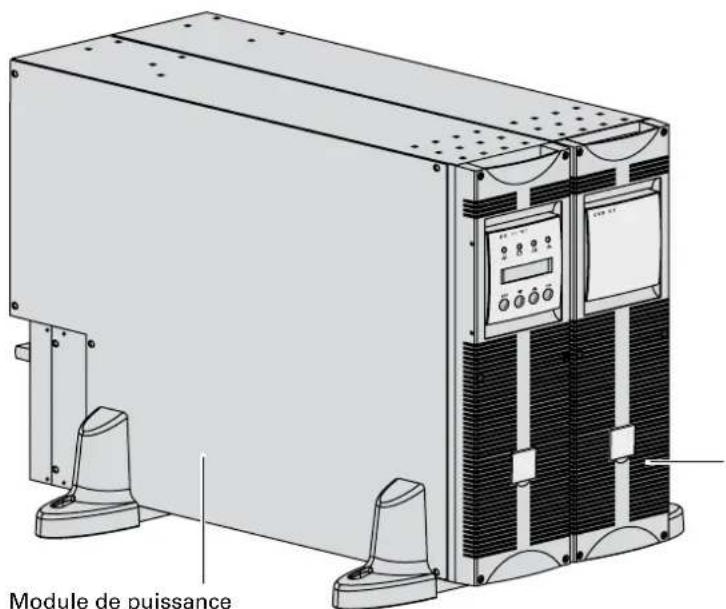
1. Présentation
Module batterie

2. Installation

2. Installation
2.4 Ports de communication


2. Installation


Mode Normal (double conversion)

4. Maintenance
ASI Alimentation Sans Interruption.
Installations- und
Bedienungsanleitung
Einführung
| Abmessungen in mm (H x B x T) | |
| EX RT 5EX RT 7EX RT 11EX RT EXB 7EX RT EXB 11 | 444 x 131 x 635 |
| Gewicht in kg | |
| EX RT 5EX RT 7 | 22.5 |
| EX RT 11 27.5 | |
| EX RT EXB 7 64.5 | |
| EX RT EXB 11 68.5 |
Batteriemodul
(EX RT EXB 7/11)
| Abmessungen in mm (H x B x T) | |
| EX RT 5EX RT 7EX RT 11EX RT EXB 7EX RT EXB 11 | 131 (3U) x 444 x 635 |
| Gewicht in kg | |
| EX RT 5EX RT 7 | 22.5 |
| EX RT 11 27.5 | |
| EX RT EXB 7 64.5 | |
| EX RT EXB 11 68.5 |
Batteriemodul
(EX RT EXB 7/11)
Batteriemodul (EX RT EXB)
USV-Modul
(EX RT 5/7/11)
Trafomodul (EX RT)
| Autonomiezeit | Empfohlene Batteriekapazität | ||
| EX RT 5 EX RT 7 EX RT 11 | |||
| 2 Stunden | 50 Ah 65 Ah 100 Ah | ||
| 4 Stunden | 100 Ah 130 Ah 200 Ah | ||
| 8 Stunden | 200 Ah 260 Ah 400 Ah | ||
Batteriemodul

Erforderliches Signal: ●



For further information, please visit our website: www.eaton.com
| Dimensioni in mm(A x L x P) | |
| EX RT 5EX RT 7EX RT 11EX RT EXB 7EX RT EXB 11 | 131 (3U) x 444 x 635 |
| Peso in Kg | |
| EX RT 5EX RT 7 | 22,5 |
| EX RT 11 27,5 | |
| EX RT EXB 7 6 | 4,5 |
| EX RT EXB 11 | 68,5 |
1. Presentazione
Modulo batteria

2. Installazione

2. Installazione
2. Installazione

2. Installazione


4. Manutenzione
For further information, please visit our website: www.eaton.com
1.1 Positions standards
Posición torre

| Dimensiones en mm (altura x ancho x prof.) | |
| EX RT 5EX RT 7EX RT 11EX RT EXB 7EX RT EXB 11 | 131 (3U) x 444 x 635 |
| Pesos en kg | |
| EX RT 5EX RT 7 | 22,5 |
| EX RT 11 27,5 | |
| EX RT EXB 7 6 | 4,5 |
| EX RT EXB 11 | 68,5 |
1. Presentación
Módulo de batería

2. Instalación
2. Instalación

2. Instalación

2. Instalación


4. Mantenimiento
For further information, please visit our website: www.eaton.com
Power module (EX RT 5/7/11)
| Afmetingen in mm (H x B x D) | |
| EX RT 5EX RT 7EX RT 11EX RT EXB 7EX RT EXB 11 | 444 x 131 x 635 |
| Gewicht in kg | |
| EX RT 5EX RT 7 | 22,5 |
| EX RT 11 27,5 | |
| EX RT EXB 7 6 | 4,5 |
| EX RT EXB 11 | 68,5 |
Batterijmodule (EX RT EXB 7/11)
Rack-opstelling

| Afmetingen in mm (H x B x D) | |
| EX RT 5EX RT 7EX RT 11EX RT EXB 7EX RT EXB 11 | 131 (3U) x 444 x 635 |
| Gewicht in kg | |
| EX RT 5EX RT 7 | 22,5 |
| EX RT 11 27,5 | |
| EX RT EXB 7 6 | 4,5 |
| EX RT EXB 11 | 68,5 |
Batterijmodule (EX RT EXB 7/11)
1. Beschrijving
1.2 Achterpanelen
Power module EX RT 5/7/11

Batterijmodule EX RT EXB 7/11

Batterijmodule (EX RT EXB)
Power module (EX RT 5/7/11)
Transformer module (EX RT)
Ingang van normale AC-net

27

28


24
![graph TD A["Assembly: 150 mm part"] --> B["Step 1: Top part with two flanges"] B --> C["Step 2: Top part with two flanges"] C --> D["Step 3: Top part with flanges"] D --> E["Step 4: Top part with flanges"] E --> F["Step 5: Top part with flanges"] F --> G["Final Assembly: Panel with monitor, screwdri…](/content/2026/06/1292976/images/4214c0fbec6f5d7769580d4bf164a518979fc807891f583bb8c8d3753499d721.jpg)

2. Installeren

Rackmontage van power of batterijmodule
(optionele rails vereist, ref. 68001)


2. Installeren

2. Installeren

2. Installeren


4. Onderhoud
For further information, please visit our website: www.eaton.com
5.1 Technische speci caties
Elektrische speci caties




- INTRODUCTION
- ENVIRONMENTAL PROTECTION
- USING THIS DOCUMENT
- ICONS
- PRESENTATION
- 1.1 STANDARD CON GURATIONS 5
- 1.2 REAR PANELS 6
- 1.3 DISPLAY AND CONTROL PANEL 7
- 1.4 OPTIONS 7
- INSTALLATION
- 2.1 UNPACKING AND PARTS CHECK 11
- 2.2 INSTALLATION IN TOWER CON GURATION 12
- 2.3 INSTALLATION IN RACK CON GURATION 13
- 2.4 COMMUNICATION PORTS 16
- 2.5 INSTALLATION DEPENDING ON THE SYSTEM EARTHING ARRANGEMENT (SEA) 18
- 2.6 REQUIRED PROTECTIVE DEVICES AND CABLE CROSS-SECTIONS 20
- 2.7 CONNECTIONS OF INPUT/OUTPUT POWER CABLES 21
- CONTENTS
- OPERATION
- MAINTENANCE
- APPENDICES
- 1.1 STANDARD CON GURATIONS
- 1.2 REAR PANELS
- 1.3 DISPLAY AND CONTROL PANEL
- 1.4 OPTIONS
- RACK MOUNTING KITS
- TRANSFORMER FOR GALVANIC ISOLATION OR EARTHING ARRANGEMENT CHANGE (PART NUMBER 68003)
- BATTERY EXTENSIONS FOR UPS BACKUP TIMES UP TO 60 MINUTES (AT FULL LOAD)
- CLA MODULE (LONG BACKUP TIME CHARGER) FOR BACKUP TIMES FROM 2 TO 8 HOURS (PART NUMBER 68004)
- 2.1 UNPACKING AND PARTS CHECK
- 2.2 INSTALLATION IN TOWER CON GURATION
- 2.3 INSTALLATION IN RACK CON GURATION
- 2.4 COMMUNICATION PORTS
- CONNECTION TO THE RS232 COMMUNICATION PORT
- CONNECTION TO THE COMMUNICATION PORT BY RELAYS ②
- OUTPUT RELAYS SPECI CATIONS
- REMOTE POWER OFF
- REMOTE POWER OFF COMMUNICATION PORT ③
- INSTALLATION OF COMMUNICATION CARDS (OPTIONAL, STANDARD WITH THE NETWORK PACK VERSION)
- 2.5 INSTALLATION DEPENDING ON THE SYSTEM EARTHING ARRANGEMENT (SEA)
- FREQUENCY CONVERTER (WITHOUT BYPASS AC INPUT)
- HOT STAND BY
- 2.6 REQUIRED PROTECTIVE DEVICES AND CABLE CROSS-SECTIONS
- REQUIRED CABLE CROSS-SECTIONS
- 2.7 CONNECTIONS OF INPUT/OUTPUT POWER CABLES
- UPS WITH COMMON NORMAL AND BYPASS AC SOURCES
- UPS WITH SEPARATE NORMAL AND BYPASS AC SOURCES
- FREQUENCY CONVERTER
- 3.1 INITIAL START UP
- UPS PERSONALISATION
- ACCESSING PERSONALISATION WITH FRONT PANEL BUTTONS
- ACCESS TO THE PERSONALISATION THROUGH EXTERNAL SOFTWARE
- 3.2 FINAL START UP SEQUENCE
- 3.3 OPERATING MODES
- 3.4 OPERATION ON BATTERY POWER
- 3.5 RETURN OF NORMAL AC SOURCE
- 3.6 SHUT DOWN
- 4.1 TROUBLESHOOTING
- 4.2 HOT-SWAPPING THE POWER MODULE
- DISCONNECTING THE POWER MODULE
- TOWER CON GURATION
- RACK CON GURATION
- RECONNECTING THE POWER MODULE
- 4.3 HOT-SWAPPING THE BATTERY MODULE
- DISCONNECTING THE BATTERY MODULE
- RECONNECTING THE BATTERY MODULE
- THE BATTERY MODULE CAN BE REPLACED. THE CONNECTED EQUIPMENT IS POWERED BY THE UPS
- TO REMOVE BATTERY TRAYS
- TO RECONNECT BATTERY TRAYS
- 4.4 TRAINING CENTER
- 5.1 TECHNICAL SPECI CATIONS
- ELECTRICAL CHARACTERISTICS
- SELECTION OF PROTECTION DEVICES
- SHORT-CIRCUIT CURRENT PROVIDED BY THE UPS IN NORMAL OR BATTERIE MODE
- EX RT CLA MODULE
- THERMAL CHARACTERISTICS
- 5.2 GLOSSARY
- NORMAL (DOUBLE CONVERSION) MODE
- 1.1 POSITIONS STANDARDS
- PRÉSENTATION
- 2.4 PORTS DE COMMUNICATION
- EINFÜHRUNG
- PRESENTAZIONE
- INSTALLAZIONE
- MANUTENZIONE
- PRESENTACIÓN
- INSTALACIÓN
- MANTENIMIENTO
- BESCHRIJVING
- 1.2 ACHTERPANELEN
- INSTALLEREN
- RACKMONTAGE VAN POWER OF BATTERIJMODULE
- ONDERHOUD
- 5.1 TECHNISCHE SPECI CATIES
- ELEKTRISCHE SPECI CATIES
Brand : EATON
Model : EX RT 7 3:1 Network
Category : Uninterruptible power supply