
CRS-WM-TA869 - Motion detector BOSCH - Free user manual and instructions
Find the device manual for free CRS-WM-TA869 BOSCH in PDF.


| Product type | Passive infrared motion detector |
| Brand | Bosch |
| Model | CRS-WM-TA869 |
| Detection technology | Passive infrared (PIR) |
| Detection angle | 90° to 120° |
| Maximum range | 10 to 12 meters |
| Power supply | 220-240 V AC, 50-60 Hz |
| Power consumption | < 0.5 W in standby |
| Operating temperature | -10°C to +40°C |
| Protection rating | IP44 |
| Dimensions (L x H x D) | 120 x 80 x 60 mm |
| Weight | 150 g |
| Housing material | UV-resistant plastic |
| Main functions | Motion detection, automatic lighting, adjustable timer |
| Adjustments | Brightness threshold, timer (5 seconds to 10 minutes) |
| Recommended use | Indoor or sheltered outdoor |
| Maintenance and cleaning | Clean with a soft dry cloth, do not use solvents |
| Safety | CE compliant, double insulation |
| Spare parts and repairability | No spare parts available, device not repairable |
Frequently Asked Questions - CRS-WM-TA869 BOSCH
User questions about CRS-WM-TA869 BOSCH
0 question about this device. Answer the ones you know or ask your own.
Ask a new question about this device
Download the instructions for your Motion detector in PDF format for free! Find your manual CRS-WM-TA869 - BOSCH and take your electronic device back in hand. On this page are published all the documents necessary for the use of your device. CRS-WM-TA869 by BOSCH.
USER MANUAL CRS-WM-TA869 BOSCH
natural_image
White rectangular device with a curved black top and a circular base (no visible text or symbols)ISA-WM-869
CRS-WM-TA869

BOSCH
de Installationshandbuch
en Installation Manual
area
| Distance (m) | Value | | ------------ | ----- | | 0 | 0 | | 3 | 2.3 | | 6 | 2.3 | | 9 | 2.3 | | 12 | 2.3 |natural_image
Silhouette of a person running with arrows indicating motion, no text or symbols present
natural_image
Silhouette of a person walking through a canopy with directional arrows indicating movement (no text or symbols)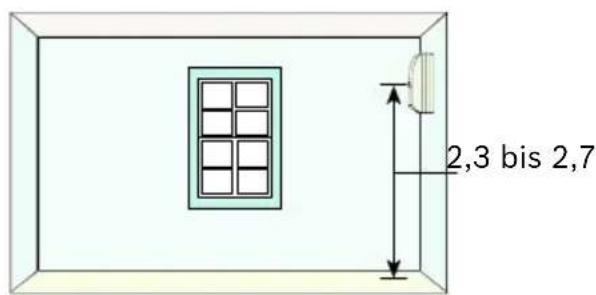
1

natural_image
Diagram of a curved mechanical component with a downward arrow and label '2' (no text or symbols on the diagram itself)natural_image
Diagram showing a device with a curved internal component and a close-up view of the interior panel (no text or symbols)natural_image
Illustration of a hand inserting into a device into a housing, showing internal components and directional arrows (no text or symbols)natural_image
Diagram of a device interior showing internal components and a hand inserting a cable (no text or symbols present)other
| x (m) | y (m) | |-------|-------| | 0 | 0 | | 3 | 0 | | 6 | 0 | | 9 | 0 | | 12 | 0 |
area
| X-axis (m) | Y-axis (m) | |---|---| | 0 | 0 | | 3 | 2.3 | | 6 | 0 | | 9 | 0 | | 12 | 0 |natural_image
Diagram of a curved mechanical component with an upward arrow labeled '1' (no text or symbols on the diagram itself)
natural_image
Diagram of a device with lock and padlock icons, no text or symbols present2
Inbetriebnahme
Parametrierung
Energiesparmodus
natural_image
Technical diagram of a battery pack with multiple cylindrical components and a switch, no visible text or symbols
natural_image
Symbol of a trash bin crossed with no text or labels, representing waste sorting or disposal (no text present)© Bosch Security Systems, 2008
Initial Operation 18
Configuration 18
Walk test mode 18
Energy-saving mode 19
Service Information 19
Technical Specifications 20
Triggers 20
Environmental conditions 20
Housing 20
Power supply requirements 20
Send and receive properties 21
Infrared detector 21
Certificates and approvals 21
Product Description
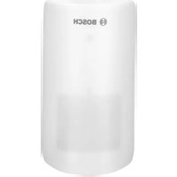
The ISA-WM-869 Wireless Motion Detector (passive infrared detector) is operated in combination with Carephones (HTS3100, HTS5x, HTS10, HTS12). The detector is used to monitor a room and to wirelessly transmit alarms to the HTS.
The activity monitor in the HTS can be reset via the daily button and the Wireless Motion Detector. In this instance, the detector serves as an external daily button for the HTS. It consists of a passive infrared detector and a wireless transmitter module, both of which are powered by batteries.
The detector is installed inside the residence in a room that the person requiring assistance has to pass through when they are at home, e.g. in the corridor. The activity monitor in the HTS will only be reset if movement is detected by the detector in this room.
Unlike triggering via the daily button, there is no announcement if triggering occurs via the detector. This is suppressed.
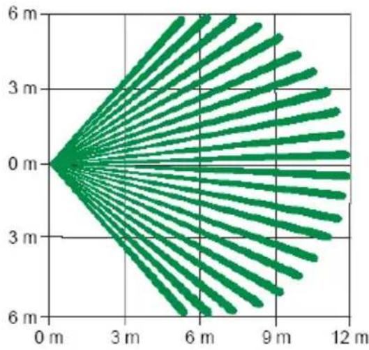
With 79 zones in eight detection levels, the detector's rays are very dense, which enables exceptional detection performance.
The housing (tamper) and wall tamper contact (wall tamper contact only used with wall mounting) transmits an alarm message if the cover is removed from its base or the unit is torn off the wall.
Project Planning
• Installation and initial operation should only be carried out by trained service personnel.
- The installation location must be within the reception range of the HTS. There must be good radio signal reception. See Initial Operation.
- The detector has a range of up to 300 m in open space. In normal operation, the actual HF range depends on the building construction, among other things.
- The detector is only suitable for living spaces.
- The detector must not be directed toward window surfaces.
- Do not install in direct sunlight.
- Do not direct toward objects that experience significant changes in temperature.
- Do not direct toward rotating machines.
• Installation on metal surfaces can impair the range of the radio signal.
- Pet immunity for pets weighing ≤ 14 kg.
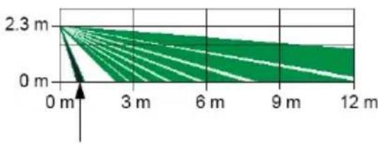
- The detector is fitted with a look-down zone film, on which the monitoring zone is deactivated; see figure below. This prevents false alarms being triggered by pets. By removing the look-down zone film, this monitoring zone is activated.
Side-view of monitoring zone
area
| Distance (m) | Value | | ------------ | ----- | | 0 | 0 | | 3 | 2.3 | | 6 | 2.3 | | 9 | 2.3 | | 12 | 2.3 |Monitoring zone without/with look-down zone film
Installation
- Select the installation location and determine the installation height.

natural_image
Two identical diagrams showing a person walking with directional arrows and shaded angles, no text or symbols present.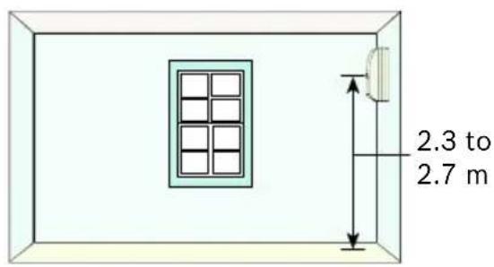
- Remove the top of the housing from the base.

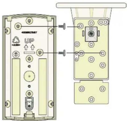
- If necessary, install the detector base with a:
3.1. Wall mounting kit. When also using a housing contact as a wall tamper contact, pull out the "wall insert" and screw it to the wall.

3.2. Corner mounting kit.

3.3. Mounting kit with pivoting wall bracket (optional).

The vertical pivoting range is +10° to -20°; the horizontal pivoting range is ±25°.

Note: Pet immunity is no longer guaranteed when using this bracket.
3.4. Installation kit with pivoting ceiling bracket (optional).

natural_image
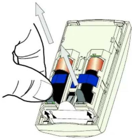
Diagram showing a device with a lid and a close-up view of its internal structure, no text or symbols present.- Remove the battery interrupter for the supply voltage.
natural_image
Illustration of a hand inserting into a device into a container with internal components (no text or symbols)- If necessary, remove the look-down zone film.

natural_image
Illustration of a hand inserting a device into a device casing, showing internal components and wiring (no text or symbols)The vertical pivoting range is +7° to -16°; the horizontal pivoting range is ±45°.

Note: Pet immunity is no longer guaranteed when using this bracket.

Top-view of monitoring zone
other
| x (m) | y (m) | |-------|-------| | 0 | 0 | | 3 | 0 | | 6 | 0 | | 9 | 0 | | 12 | 0 |Side-view of monitoring zone

line
| Time (m) | Value | | -------- | ----- | | 0 | 2.3 | | 3 | ~1.5 | | 6 | ~1.0 | | 9 | ~0.8 | | 12 | ~0.7 |- Fit the top of the housing onto the housing base and close the detector. Once the housing is closed, the LED flashes until a 1.5-second idle period (without recognized movement) has been completed.

natural_image
Diagram of a curved mechanical component with an upward arrow and label '1' (no text or symbols on the diagram itself)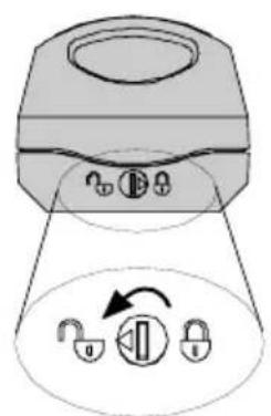
natural_image
Diagram of a device with a lock and padlock icon, no text or symbols present2
Initial Operation
Configuration
The detector has its own individual code, which must be communicated to the HTS (see HTS Programming Manual). The detector can be registered by opening the tamper contact (opening the housing) (see HTS Programming Manual).
Walk test mode
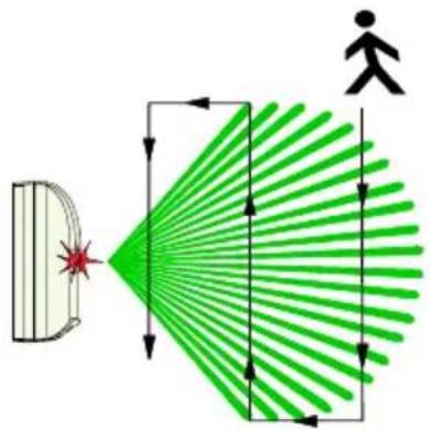
Once the batteries have been inserted and the tamper contact has been closed, the detector will be in walk test mode for 90 seconds.
Each time a movement is detected, the time will be reset. During the last 10 seconds, the LED flashes to indicate that the walk test function is about to end. During this time, there should be no movement.
While in walk test mode, no alarms will be forwarded to the HTS. When movement is detected, the LED lights up for 4 seconds.
Energy-saving mode
After 90 seconds, the detector enters energy-saving mode, i.e. after an alarm has been triggered, no further detected movements will be reported to the HTS for 12 minutes.
Energy-saving mode does not apply for the housing (tamper) and wall tamper contact.
Service Information

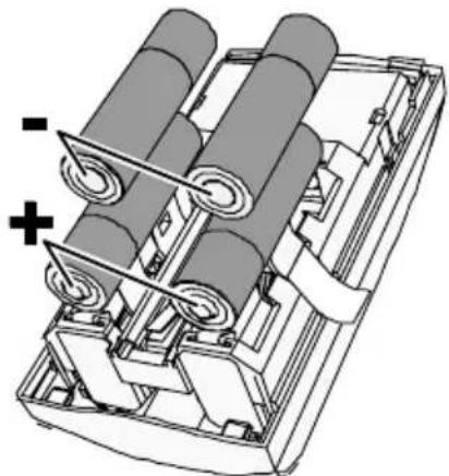
Caution when replacing batteries: ensure correct polarity!
4 x 1.5 V alkaline cells (AA)
natural_image
Technical diagram of a mechanical device with rollers and a switch, no visible text or symbols
Note: Always carry out a function test after replacing the batteries.

natural_image
Symbol of a trash bin crossed with no visible text or labelsBattery disposal: Battery distributors are required by law to take back spent batteries; they must not be thrown away as household waste. Please return used (rechargeable) batteries to your specialist retailer or take them to a recycling center intended for this purpose.
Technical Specifications
Triggers
| Passive infrared detector | Movement in monitoring zone. |
| Housing and wall tamper contact (depending on installation) | Transmits an alarm message if the top of the housing is removed from the base or if the detector is torn off the wall. |
Environmental conditions
| Environment Indoors, dry | |
| EN50131-1 Environmental class II | |
| Relative humidity | Up to 95%, non-condensing |
| Operating temperature | -10 °C to +55 °C |
| Storage temperature | -20 °C to +80 °C |
Housing
| Color Cream white | |
| Dimensions(H x W x D) | 12.2 x 6.2 x 5.2 cm |
Power supply requirements
| Battery durability | From 18 months to 4 years, depending on the area of installation and number of transmissions. |
| Battery requirements | Four 1.5 V alkaline cells (AA) |
| Recommended batteries | - Duracell® MN1500 or PC1500- Eveready® E91- Panasonic® AM-3PIX/B |
| Supply voltage 2 | 3 VDC to 3.0 VDC |
| Automatic test signal | Every 24 hours at least |
| Message: "Battery Low" | On activation or automatic test signal. Following a "Battery Low" message, the battery should be changed within one week. |
Send and receive properties
| Frequency 869.21 | 25 MHz |
| Max. modulating frequency | Bosch: < ± 2.5 kHzTA: < ± 1.25 kHz |
| Bandwidth of band used | 25 kHz |
| Modulation type F | FSK (frequency shift keying) / ITU F1D |
| Modulation hub of sender | ± 3 kHz |
| Transmission power | - 3 dBm (0.5 mW)(Class B transmission power conforms to EN300220) |
| Transmission rate | Bosch: 0 - 1600 HzTA: 0 - 2500 Hz |
| Range(unobstructed) | > 300 m |
Infrared detector
| Installation height | 2.3 to 2.7 m |
| Monitoring zone | 12 m x 12 m |
Certificates and approvals
| Approvals CE 0682 | |
| Conforms to EN50 | 131-1 Class 2,Environmentalclass II |
Bosch Security Systems Ltd
Broadwater Park
North Orbital Road
Denham
UB9 5HN
Tel.: 01895-878088
Fax.: 01895-878089
uk.securitysystems@bosch.com
www.boschsecurity.co.uk
© Bosch Security Systems, 2008
Table des matières
area
| Distance (m) | Value | | ------------ | ----- | | 0 | 0 | | 3 | 2.3 | | 6 | 2.3 | | 9 | 2.3 | | 12 | 2.3 |natural_image
Two identical diagrams showing a person walking with directional arrows, possibly illustrating motion or safety (no text or symbols present)
natural_image
Diagram showing a device with a curved panel and a vertical pipe inserted into a housing (no text or symbols)natural_image
Illustration of a hand inserting into a device into a container with arrows indicating direction (no text or symbols)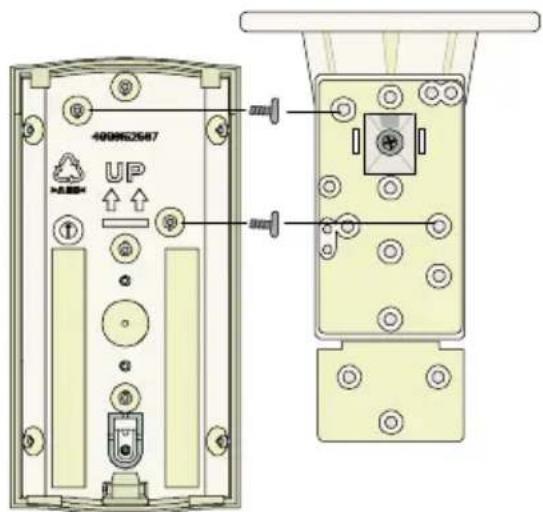
natural_image
Illustration of a hand inserting a device into a device casing, showing internal components and a tool (no text or symbols)natural_image
Diagram of a curved mechanical component with an upward arrow and label '1' (no text or symbols on the diagram itself)
natural_image
Diagram of a device with three keys and an open padlock icon, no text or symbols present2
Mise en service
Configuration
natural_image
Technical diagram of a mechanical device with rollers and a switch, showing internal components without any text or symbols.
natural_image
Symbol of a trash bin crossed with no text or labels, representing waste sorting or disposal (no text present)Bosch Security Systems France
Atlantic 361
© Bosch Security Systems, 2008
Bosch Security Systems nv/sa
Torkonjestraat 21 F
B-8510 Marke
Belgium
Tel: +32 56 20 02 40
Fax: +32 56 20 26 75
be.securitysystems@bosch.com
www.boschsecurity.be
© Bosch Security Systems, 2008
Inhoudsopgave
natural_image
Two identical diagrams showing a person walking with directional arrows and shaded angles, no text or symbols present.
1

natural_image
Diagram of a curved mechanical component with an arrow labeled '2' pointing downward (no text or symbols on the diagram itself)natural_image
Diagram showing a device with a curved internal component and a separate 3D box with a handle, connected by an arrow (no text or symbols present)natural_image
Illustration of a hand inserting into a device into a container with internal components (no text or symbols)natural_image
Illustration of a hand inserting a device into a device casing, showing internal components and wiring (no text or symbols)

natural_image
Diagram of a curved mechanical component with an upward arrow and label '1' (no text or symbols on the diagram itself)
2
Inbedrijfstelling
Configuratie
Energiebesparingsmodus
natural_image
Technical diagram of a mechanical device with rollers and a switch, no visible text or symbols
natural_image
Symbol of a trash bin crossed with no text or labels, representing waste sorting or disposal (no text present)Bosch Security Systems BV
Postbus 80002
Bosch Security Systems nv/sa
Torkonjestraat 21 F
B-8510 Marke
Belgium
Tel: +32 56 20 02 40
Fax: +32 56 20 26 75
be.securitysystems@bosch.com
www.boschsecurity.be
© Bosch Security Systems, 2008
Bosch Security Systems
For more information please visit
www.boschsecurity.com
or send an e-mail to
emea.securitysystems@bosch.com
- ISA-WM-869
- CRS-WM-TA869
- BOSCH
- Inbetriebnahme
- Parametrierung
- Energiesparmodus
- Initial Operation 18
- Service Information 19
- Technical Specifications 20
- Product Description
- Project Planning
- Installation
- Initial Operation
- Configuration
- Walk test mode
- Energy-saving mode
- Service Information
- Technical Specifications
- Bosch Security Systems Ltd
- Table des matières
- Mise en service
- Bosch Security Systems France
- Bosch Security Systems nv/sa
- Inhoudsopgave
- Inbedrijfstelling
- Configuratie
- Energiebesparingsmodus
- Bosch Security Systems BV
- Bosch Security Systems
Brand : BOSCH
Model : CRS-WM-TA869
Category : Motion detector