QLIMA R133TC - Frying Pan

R133TC - Frying Pan QLIMA - Free user manual and instructions

Find the device manual for free R133TC QLIMA in PDF.

📄 162 pages English EN Download 💬 AI Question 10 questions ⚙️ Specs
Notice QLIMA R133TC - page 64
Pick your language and provide your email: we'll send you a specifically translated version.
Product type Pellet stove
Brand Qlima
Model R133TC
Dimensions (W x D x H) 600 x 530 x 1000 mm
Net weight 105 kg
Power supply 230 V / 50 Hz
Nominal heating power 10 kW
Energy efficiency >90 %
Hopper capacity 15 kg
Maximum autonomy Up to 30 hours
Hourly consumption 0.5 to 1.5 kg/h
Flue pipe diameter 80 mm
Combustion type Controlled combustion with fan
Main functions Weekly programming, room thermostat, remote control
Maintenance and cleaning Daily cleaning of burner pot, weekly ash vacuuming, annual flue sweeping
Safety Automatic shutdown in case of overheating, safety ventilation, rear fire safety
Spare parts available Yes, hopper, burner pot, fan, temperature sensor
Repairability Repairability index not communicated
Noise level Approximately 45 dB(A)
Energy class A+

Frequently Asked Questions - R133TC QLIMA

How to clean the Qlima R133TC stove?
It is recommended to clean the burner pot daily and vacuum the ashes once a week. Annual flue sweeping is mandatory.
Which pellets to use with this stove?
Use certified wood pellets ENplus A1, diameter 6 mm, with moisture content below 10%.
The stove displays an error code, what to do?
Check the manual for the specific error code. Common causes include lack of pellets, burner pot obstruction, or ignition failure. If the problem persists, contact a professional.
How to turn on the stove for the first time?
Make sure the hopper is full, plug in the appliance, then press the On/Off button. The stove performs an automatic ignition cycle. Wait for a stable flame before adjusting the temperature.
How to adjust the room temperature?
Use the integrated thermostat or the remote control to select the desired temperature (usually 15-30 °C). The stove automatically modulates its power.
What are the safety instructions?
Maintain a minimum distance of 1 meter from flammable objects. Never cover the appliance. In case of overheating, the stove shuts down automatically.
What are the exact dimensions of the stove?
The dimensions are 600 x 530 x 1000 mm (W x D x H). Make sure to allow enough space for installation and access to the hopper.
Is the power supply standard?
Yes, the stove operates on a standard 230 V / 50 Hz outlet. The maximum electrical consumption is about 300 W during operation.
What maintenance is needed before winter?
Before the heating season, check the condition of the burner pot, clean the flue pipe, and replace the door gasket if necessary. Call a chimney sweep.
Can the stove be controlled remotely?
Yes, the supplied remote control allows adjusting the temperature, programming, and turning the stove on/off remotely. Some models are compatible with a mobile app (optional).

User questions about R133TC QLIMA

0 question about this device. Answer the ones you know or ask your own.

Ask a new question about this device

The email remains private: it is only used to notify you if someone responds to your question.

No questions yet. Be the first to ask one.

Download the instructions for your Frying Pan in PDF format for free! Find your manual R133TC - QLIMA and take your electronic device back in hand. On this page are published all the documents necessary for the use of your device. R133TC by QLIMA.

USER MANUAL R133TC QLIMA

Technical line drawing of a mechanical device with no visible text or symbols

INTERDICTION

LE COMBUSTIBLE APPROPRIÉ

MANUEL

QLIMA R133TC - MANUEL - 1

A INSTALLATION DE L'APPAREIL

Technical line drawing of a mechanical device with a metal bracket and fan (no text or symbols)

Diagram of a hand using a tool to adjust or install a component, with no visible text or symbols.

Technical line drawing of a door panel with mounting holes and a label 'G' (no text or symbols beyond basic diagram)

Diagram of a mechanical device with a fan and handle, showing internal components and an arrow indicating direction (no text or symbols present)

Diagram of a water tank with a connected gas bag and a recycling symbol, no text or labels present.

D FONCTIONNEMENT DE L'APPAREIL

E EXTINCTION DE L'APPAREIL

Simple line drawing of a mortar or pestle with a handle and base (no text or symbols)

K CONDITIONS DE GARANTIE

Illustration of a portable electric heater with a hand inserting a plug, shown alongside an inset view of its door panel (no text or symbols present)

Technical illustration of a device with an open lid and internal components (no text or symbols)

Technical line drawing of a mechanical assembly with gears and components (no text or symbols)

Technical line drawing of a mechanical device with labeled parts A and B (no text or symbols beyond labels)

Line drawing of a handheld device with a central hub and wiring (no text or symbols)

Mechanical component diagram showing a cylindrical assembly with an arrow indicating direction (no text or symbols)

Technical line drawing of a mechanical device with a cylindrical component and a base plate (no text or symbols)

Diagram illustrating a cooking process with labeled steps: boiling, heating, and drying.

Mechanical assembly diagram showing a hand holding a component over a circular housing (no text or symbols visible)

Line drawing of a hand holding a curled-up, segmented object (no text or symbols)

Illustration of a mechanical device with hands operating it, no visible text or symbols

Technical line drawing of a mechanical component with no visible text or symbols

Technical line drawing of a mechanical component (no text or symbols visible)

LE CHANGEMENT DE LA MÈCHE

L AVANT DE COMMENCER A CHANGER LA MECHE, L'APPAREIL DOIT ÊTRE ETEINT ET TOTALEMENT REFROIDI.

Technical line drawing of a mechanical assembly with no visible text or symbols

5/16" 17

Technical line drawing of a mechanical clutch assembly (no text or symbols)

Technical line drawing of a mechanical device with no visible text or symbols

Technical line drawing of a mechanical component with no visible text or symbols

Technical line drawing of a mechanical assembly with no visible text or symbols

A B 22

Technical line drawing of a mechanical device with no visible text or symbols

Technical illustration of a device with internal components and a separate open base (no text or symbols)

Illustration of a hand inserting a plug into a device labeled '25' (no text or symbols on the device itself)

Line drawing of a portable electronic device with ventilation slots and a handle (no text or symbols)

Hand inserting a component into a device casing (no text or symbols visible)

Technical line drawing of a mechanical device with no visible text or symbols

Technical illustration of a kitchen appliance with fan, vent, and cooling unit (no text or symbols)

GEBRAUCHSANWEISUNG

QLIMA R133TC - GEBRAUCHSANWEISUNG - 1

A DIE INSTALLATION DES KAMINOFENS
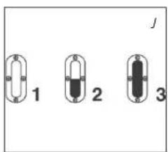
Diagram of a hand using a tool to adjust or install a component, with no visible text or symbols.

Technical line drawing of a door panel with mounting holes and a label 'G' (no text or symbols beyond basic diagram)

Diagram of a mechanical device with a fan and housing, showing internal components and an upward arrow (no text or symbols)

Diagram of a water tank with recycling symbols and connected to a battery (no text or labels)

1 2 3

Technical line drawing of a portable air conditioner unit with ventilation grilles and control panel (no text or symbols)

Illustration of a portable air conditioner unit with a hand operating the control panel (no text or symbols visible)

Technical line drawing of a door panel with mounting holes and a label 'G' (no text or symbols on the diagram itself)

Transportverschluß

Illustration of a hand inserting a heater into a door panel, showing internal components and wiring (no text or symbols)

Technical illustration of a device with an open lid and internal components (no text or symbols)

Technical line drawing of a mechanical device with no visible text or symbols

Technical line drawing of a mechanical device with labeled parts A and B (no text or symbols beyond labels)

Line drawing of a mechanical device with a central component and wiring (no text or symbols)

Mechanical component diagram showing a cylindrical assembly with an arrow indicating direction (no text or symbols)

Technical line drawing of a mechanical device with a cylindrical component and a rectangular base (no text or symbols)

Diagram illustrating a cooking process with labeled steps: boiling, heating, and drying.

Mechanical assembly diagram showing a hand operating a rotating component with a spring and lever (no text or symbols)

Simple line drawing of a hand holding a curled-up, no text or symbols present

Line drawing of a mechanical device with a cylindrical top and base, emitting motion lines (no text or symbols)

Technical line drawing of a mechanical component with no visible text or symbols

Technical line drawing of a mechanical component (no text or symbols visible)

WECHSELN DES DOCHTES

Technical line drawing of a mechanical assembly with no visible text or symbols

5/16" 17

Technical line drawing of a mechanical clutch assembly (no text or symbols)

Technical line drawing of a mechanical device with no visible text or symbols

Technical line drawing of a mechanical component with no visible text or symbols

Technical line drawing of a mechanical assembly with no visible text or symbols

A B 22

Technical line drawing of a mechanical device with no visible text or symbols

Technical illustration of a device with internal components and an open base, no visible text or symbols

Illustration of a hand inserting a plug into a device labeled '25', with an inset showing a door panel (no text or symbols on the device itself)

Line drawing of a portable electronic device with ventilation slots and a handle (no text or symbols)

Line drawing of a hand operating a device with a handle (no text or symbols visible)

HVAD MAN F∅RST SKAL VIDE

S∅RG ALTID FOR TILSTRÆKKELIG VENTILATION
Technical line drawing of a portable air conditioner unit with labeled component B (no text or symbols beyond label)

Technical line drawing of a mechanical device with no visible text or symbols

Technical illustration of a kitchen appliance with fan, vent, and cooling unit (no text or symbols)

VEJLEDNING

QLIMA R133TC - VEJLEDNING - 1

A INSTALLATION AF OVNEN

Technical line drawing of a portable air conditioner unit with ventilation grilles and control panel (no text or symbols)

Illustration of a portable air conditioner unit with a hand operating the front panel (no text or symbols visible)

Sådan gør De:

transportprop

TRANSPORT
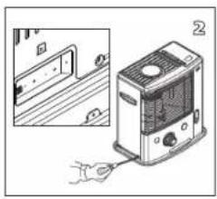
Illustration of a portable electric heater with a hand inserting a plug, shown alongside an inset view of its door and panel (no text or symbols present)

Technical illustration of a device with an open lid and internal components (no text or symbols)

Technical line drawing of a mechanical assembly with gears and components (no text or symbols)

Technical line drawing of a mechanical device with labeled parts A and B (no text or symbols beyond labels)

Line drawing of a handheld device with a central hub and wiring (no text or symbols)

Mechanical component diagram showing a cylindrical assembly with an arrow indicating direction (no text or symbols)

Technical line drawing of a mechanical assembly with a cylindrical component and a base plate (no text or symbols)

Diagram illustrating a cooking process with labeled steps: boiling, heating, and drying.

Mechanical assembly diagram showing a hand holding a component over a circular base with a bolt and shaft (no text or symbols)

Line drawing of a hand holding a curled-up, segmented object (no text or symbols)

Illustration of a mechanical device with hands operating it, no visible text or symbols

Technical line drawing of a mechanical component with no visible text or symbols

Technical line drawing of a mechanical component (no text or symbols visible)

UDSKIFTNING AF VÄGEN

L INDEN DU PÅBEGYNDER UDSKIFTNINGEN AF VÄGEN, SKAL KAMINEN VÄRE SLUKKET OG HELT AFK∅LET.
Technical line drawing of a mechanical assembly with no visible text or symbols

5/16" 17

Technical line drawing of a mechanical clutch assembly (no text or symbols)

Technical line drawing of a mechanical device with no visible text or symbols

Technical line drawing of a mechanical component with no visible text or symbols

Technical line drawing of a mechanical assembly with no visible text or symbols

A B 22

Technical line drawing of a mechanical device with no visible text or symbols

Technical illustration of a device with internal components and a base housing (no text or symbols)

Illustration of a hand inserting a plug into a device labeled '25', with an inset showing a door panel (no text or symbols on the device itself)

Illustration of a portable electronic device with ventilation slots and a handle (no text or symbols)

Line drawing of a hand operating a device with a handle (no text or symbols visible)

Technical line drawing of a mechanical device with internal components and directional arrows (no text or symbols)

Diagram of a kitchen appliance with fan, oven, and evaporator (no text or labels)

Exploded view diagram of a microwave oven assembly with labeled components and directional arrows indicating assembly steps.

MANUAL

QLIMA R133TC - MANUAL - 1

A INSTALACION DE LA ESTUFA

Diagram of a hand using a tool to adjust or install a component on a cabinet (no text or symbols visible)

Technical line drawing of a door panel with mounting holes and a label 'G' (no text or symbols beyond basic diagram)

Diagram of a mechanical device with a fan and housing, showing internal components and an upward arrow labeled 'H' (no text or symbols present)

Diagram of a water tank with recycling symbols and connected to a battery (no text or labels)

1 2 3

E

44

Technical line drawing of a portable air conditioner unit with ventilation grilles and fan (no text or symbols)

Illustration of a portable air conditioner unit with a hand operating the front panel (no text or symbols visible)

Technical line drawing of a device rear panel with buttons and a highlighted screen (no text or symbols)

Simple line drawing of a mortar or cup (no text or symbols)

Tapón de transporte

Illustration of a hand inserting a heater into a door panel, showing internal components and wiring (no text or symbols)

Technical illustration of a device with an open lid and internal components (no text or symbols)

Technical line drawing of a mechanical assembly with gears and components (no text or symbols)

Technical line drawing of a mechanical device with labeled parts A and B (no text or symbols beyond labels)

Line drawing of a handheld device with a central hub and wiring (no text or symbols)

Mechanical component diagram showing a cylindrical assembly with an arrow indicating direction (no text or symbols)

Technical line drawing of a mechanical device with a cylindrical component and a base plate (no text or symbols)

Diagram illustrating a cooking process with labeled steps: boiling, heating, and drying.

Mechanical assembly diagram showing a hand holding a component over a circular housing (no text or symbols visible)

Simple line drawing of a hand holding a curled-up, no text or symbols present

Illustration of a mechanical device with hands operating it, no visible text or symbols

Technical line drawing of a mechanical component with no visible text or symbols

Technical line drawing of a mechanical component (no text or symbols visible)

E

CAMBIAR LA MECHA

L ANTES DE COMENZAR A CAMBIAR LA MECHA, LA ESTUFA TIENE QUE ESTAR APAGADA Y COMPLETA - MENTE FRÍA.

Technical line drawing of a mechanical assembly with no visible text or symbols

5/16" 17

Technical line drawing of a mechanical component with no visible text or symbols

Technical line drawing of a mechanical device with no visible text or symbols

Technical line drawing of a mechanical clutch assembly (no text or symbols)

Technical line drawing of a mechanical device with no visible text or symbols

A B 22

Technical line drawing of a mechanical device with no visible text or symbols

Technical illustration of a device with an open lid and internal components (no text or symbols)

Illustration of a portable air conditioner unit connected to a hand holding a tool, with an inset showing a door opening (no text or symbols visible)

Line drawing of a portable electronic device with ventilation slots and a handle (no text or symbols)

Line drawing of a hand pressing down on a device component (no text or symbols visible)

KÄYTTÖOHJEET

QLIMA R133TC - KÄYTTÖOHJEET - 1

A LÄMMITTIMEN ASENTAMINEN

Technical line drawing of a mechanical housing or enclosure with internal components and directional arrows (no text or symbols)

Technical line drawing of a mechanical device with pressure gauges and control knobs (no text or symbols)

Diagram of a kitchen appliance showing fan, oven, and stove with a directional arrow (no text or labels)

Diagram of a hand operating a device with a curved arrow indicating rotation or movement (no text or symbols present)

Technical line drawing of a door panel with mounting holes and a label 'G' (no text or symbols present)

Diagram of a mechanical device with a fan and housing, showing internal components and an arrow labeled 'H' (no text or symbols present)

Diagram of a multi-tiered gas storage tank with a connected delivery bag and a valve, showing internal compartments (no text or labels)

Technical line drawing of a portable air conditioner unit with labeled ports (no text or symbols beyond 'M')

Illustration of a portable air conditioner unit with a hand operating the front panel (no text or symbols visible)

kuljetuskorkki

I KULJETUS

Illustration of a portable electric heater with a hand inserting a plug, shown alongside an inset view of its door panel (no text or symbols present)

Technical illustration of a device with an open lid and internal components (no text or symbols)

Technical line drawing of a mechanical device with no visible text or symbols

Technical line drawing of a mechanical device with labeled parts A and B (no text or symbols beyond labels)

Line drawing of a handheld electronic device with a central hub and wiring (no text or symbols)

Mechanical component diagram showing a cylindrical assembly with an arrow indicating direction (no text or symbols)

Technical line drawing of a mechanical assembly with a cylindrical component and a base plate (no text or symbols)

Diagram illustrating a cooking process with labeled steps: boiling, heating, and drying.

Mechanical assembly diagram showing a hand holding a component over a circular base with a bolt and shaft (no text or symbols)

Line drawing of a hand holding a curled-up, segmented object (no text or symbols)

Illustration of a mechanical device with hands operating it, no visible text or symbols

Technical line drawing of a mechanical component with no visible text or symbols

Technical line drawing of a mechanical component (no text or symbols visible)

SYDÄMEN VAIHTAMINEN

L VARMISTA, ETTÄ LÄMMITIN ON SAMMUTETTU JA TÄYSIN JÄÄHTYNYT, ENNEN KUIN ALOITAT SYDÄMEN VAIHTAMISEN.

Technical line drawing of a mechanical assembly with no visible text or symbols

5/16" 17

Technical line drawing of a mechanical component with no visible text or symbols

Technical line drawing of a mechanical device with no visible text or symbols

Technical line drawing of a mechanical clutch assembly (no text or symbols)

Technical line drawing of a mechanical device with no visible text or symbols

A B 22

Technical line drawing of a mechanical device with no visible text or symbols

Technical illustration of a device with a front-mounted unit and internal components (no text or symbols)

Illustration of a portable air conditioner unit connected to a hand holding a tool, with an inset showing a door opening (no text or symbols visible)

Line drawing of a portable electronic device with ventilation slots and a handle (no text or symbols)

Line drawing of a hand pressing down on a device panel (no text or symbols visible)

Congratulations on your purchase of this heater. You have purchased a quality product, which will serve you for many years to come. This, of course, provided you use the heater correctly. Please read these Directions for Use first, to ensure the maximum lifetime for your heater.

This appliance comes with a 24-month manufacturer's warranty on all defects in material or workmanship.

We wish you much warmth and comfort from your heater.

Yours sincerely,

PVG Holding b.v.

Customer Service Department

1 READ THE DIRECTIONS FOR USE FIRST.

2 IN CASE OF ANY DOUBT, CONTACT YOUR DEALER.

GB

64

GENERAL DIRECTIONS FOR USE

Below you will find the main steps to be taken for using your heater. For more details, please refer to the MANUAL (pages 67 ff.).

1 Remove all packaging materials (refer to Section A, Fig. A).
2 Fill the removable tank ⑨ and wait 30 minutes before you ignite the heater (refer to Section B, Fig. 1).
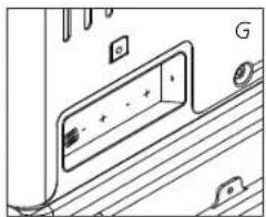
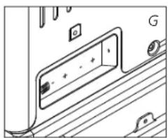
3 Insert the batteries into the battery holder ⑫ (refer to Section A, Fig. G).
4 Check whether the combustion chamber ④ is fully upright (refer to Section A, Fig. F).
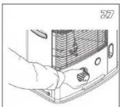
5 Ignite the heater by turning the knurled wick adjustment knob ② as far to the right as possible and then gently push the ignition button ③ (refer to Section C, Fig. K and L).
6 After igniting the heater it will take 10 to 15 minutes before you can check if the heater burns well (refer to Section D).
7 Switch off the heater (refer to Section E).

  • As a fire precaution, the tank must be filled either when the heater has been switched off or in another room than the room where the heater is installed.
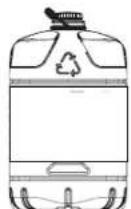
  • Always ensure that the tank is closed properly after filling it at a safe distance from all sources of heat and open flames (see chapter B).
  • Store all fuel containers with their original caps and seals in a cool and dark place.
  • Fuel ages. Use new fuel at the start of every heating season.
  • The use of Qlima Premium Quality Fuels as a heating fuel assures you that you have a good quality fuel.
  • Before changing brands and/or types of fuel make sure that the mobile heater first completely empties all of the remaining fuel inside the heater.

MAIN COMPONENTS

① OFF - button
② Knurled wick adjustment knob
③ Ignition button
4 Combustion chamber
⑤ Combustion chamber handle
6 Fuel indicator
7 Grill
⑧ Lid for removable tank
9 Removable tank
⑩ Fuel gauge removable tank
⑪ Ignition coil
12 Battery holder
13 Handle
14 Cabinet

WHAT YOU NEED TO KNOW IN ADVANCE

ALWAYS MAKE SURE THAT THERE IS SUFFICIENT VENTILATION

This device is fitted with a security system that stops it when the temperature in the room is too high. When the heater has switched off (manually or automatically) it may not be restarted for 15 minutes. In order to prevent damage to the device, please do not force the ignition of the heater during this period.

Read this user manual carefully before using the appliance and keep it for future reference. Install this device only when it complies with local/national legislation, ordinances and standards. This product is intended to be used as a heater in residential houses and is only suitable for use in dry locations, in normal household conditions, indoors in living room, kitchen and garage.

Regardless of the model, you must always make sure that the heater is used in a room large enough to enable the heater to be used safely without extra ventilation. If the room is smaller than required, you must always open a door or window slightly (ensuring an opening of approx. 2.5 cm). It is important that every room where the heater is used has sufficient air intake and efficient air outflow (both openings must have a minimum cross section of 50 cm 2 ). No modifications to the safety system are allowed, as that will invalidate the guarantee that the air probe will work properly. Consult your dealer in case of doubt.

SAFETY SYSTEM

When you have turned on the heater, if the room temperature is relatively low (19 to 20°C) it may automatically switch off. The cause of this is build-up of heat in the heater. This is a logical consequence of the safety mechanism. This will not occur when using the heater at lower ambient temperatures.

QLIMA R133TC - SAFETY SYSTEM - 1

SAFE TOP

The heater is supplied with a safe top. This application decreases the temperature of the top plate. In this way, the risk of harmful accidents at accidentally touching the top plate is considerably decreased. However, be aware that the top plate still becomes hot.

Avoid any contact with the top plate and grille.

Especially for France: Your heater was designed to operate exclusively on fuel for liquid fuel-operated mobile heaters in accordance with the Decrees of 18-07-2002 and 25-06-2010. The use of other fuels is forbidden. Ask your dealer or check our website for the addresses of our retailers. The liquid fuel-operated mobile heater is intended as an extra heater, and not as a continuous source of heat.

Especially for United Kingdom: Only use Class C1 paraffin fuel in accordance with BS2869; Part 2, or equivalent.

The user must comply with the following instructions for proper use:

DO NOT

  • use the liquid fuel-operated mobile heater in caravans, boats, and vehicle cabins;
  • use the liquid fuel-operated mobile heater in insufficiently ventilated rooms (consult the table of properties for the minimum dimensions of the room to be heated), underground rooms and / or at a height of over 1500 metres;
  • modify the heater safety features.

The use of this type of heating in public rooms is subject to prior regulatory permission. Obtain proper information on this in advance.
QLIMA R133TC - DO NOT - 1
Only the use of the correct fuel will ensure safe, efficient, and comfortable use of your heater.

THE RIGHT FUEL

Your heater has been designed for use with high-quality water-free pure paraffin oil like Qlima Premium Quality Fuels. Only fuels of this kind will ensure clean and proper burning. Lower quality fuel may result in:

▶ excessive tar deposits on the glass fibre wick
▶ incomplete burning
▶ reduced heater lifetime
▶ smoke and/or smells
▶ deposits on the grid or mantle

Using the right fuel is therefore essential for safe, efficient, and comfortable use of your heater.

Damage and/or malfunctions of the heater due to the use of other than high quality water-free pure paraffin oil is not covered by the warranty.

Always refer to your local dealer for the right fuel for your heater.

Exploded view diagram of a microwave oven system showing internal components and assembly (no text or labels)

Technical line drawing of a portable air conditioner unit with labeled ports (no text or symbols beyond labels)

Technical line drawing of a mechanical device with no visible text or symbols

Technical line drawing of a kitchen appliance with fan, vent, and door (no text or symbols)

MANUAL

QLIMA R133TC - MANUAL - 1

A INSTALLING THE HEATER

1 Carefully remove your heater from the box and check the contents. In addition to the heater you also need to have:

▶ a transportation cap
▶ these directions for use

Keep the box and the packaging materials (Fig. A) for storage and/or transportation.

2 Remove the other packaging materials:

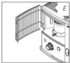
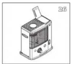
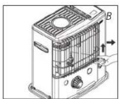
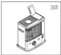
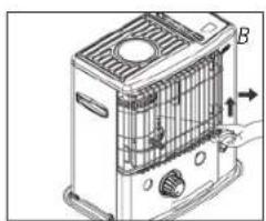
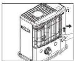
▶ Release the right side of the grill. Lift the grill from the slot (Fig. B) and pull it forward.
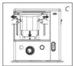
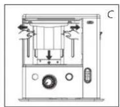
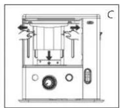
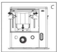
▶ Pull both ends of the packaging to the sides and at the same time slightly downwards (see Fig. C).
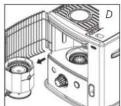
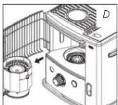
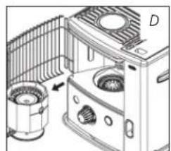
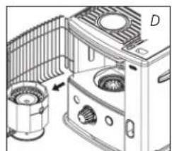
▶ Remove the combustion chamber from the heater and remove the packaging underneath (see Fig. D).

GB

67

QLIMA R133TC - A INSTALLING THE HEATER - 1

1 2 3

GB

68

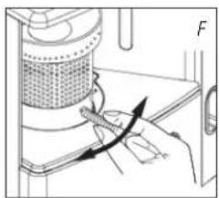
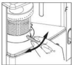
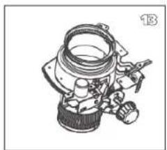
▶ Put the combustion chamber back into its place. The combustion chamber is positioned correctly when it can be smoothly moved a little to the left and to the right by its handle ⑤ (Fig. F). Close the grill: Slightly lift it to reposition it in its slot.
▶ Open the lid of the removable tank ④ and remove the piece of polyfoam.

3 Fill the removable tank as indicated in Section B.
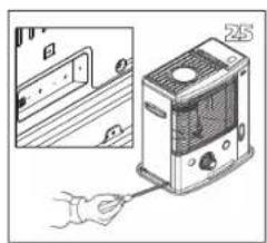
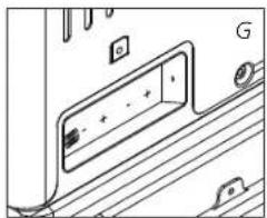
4 Insert the batteries into their holder 12 at the back of the heater (Fig. G). Ensure that the positive and negative poles match the + and - marks indicated on the battery housing. Close the battery cover.
5 The floor should be firm and completely level. Reposition the heater, when it is not level. Do not correct the situation by placing books or other goods under the heater. Please refer to the separate instructions in the carton box for fixing of the heater.
6 Your heater is now ready for use.

B FILLING FUEL

Fill the removable tank in a suitable place since there can always be some spillage. Follow the procedure below:

1 Make sure that the heater is switched off.
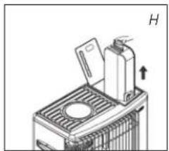
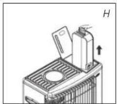
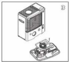
2 Open the upper lid and lift the removable tank out of the heater (Fig. H). Note: Some drops may leak from the tank. Put down the removable tank (cap pointing upwards, handle on floor and screw off the fuel cap.
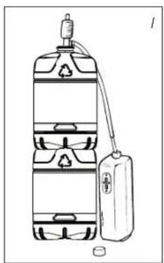
3 Fill the removable tank using a fuel pump (refer to fuel pump operation instructions.) Make sure that it is in a higher position than the removable tank (Fig. 1). Insert the ribbed hose into the opening of the removable tank.
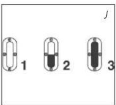
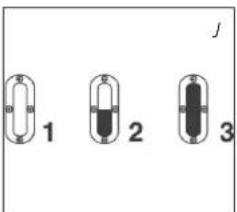
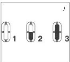
4 Check the removable tank fuel gauge while filling the tank (Fig. J). Stop filling once the gauge indicates that the tank is full. Never overfill the tank, especially not when the fuel is very cold (fuel expands when it heats up).
5 Let the remaining fuel in the pump flow back into the jerry can and carefully remove the pump. Carefully screw the fuel cap back on the tank. Clean off any spilled fuel.
6 Check whether the fuel cap is straight and tightened properly. Reinstall the removable tank in the heater (cap down). Close the lid.

C IGNITING THE HEATER

A new heater may give off some smells for a short while, when it is used for the first time. You should therefore provide extra ventilation or ignite the heater outside the living room.

QLIMA R133TC - C IGNITING THE HEATER - 1

When you use the heater for the first time, first put the filled removable tank into place, and then wait approximately 30 minutes before you ignite the heater. This allows the glass fibre wick to soak up the fuel. Follow the same procedure when you have completely burnt up all fuel from the tank, and after the glass fibre wick has been replaced.

QLIMA R133TC - C IGNITING THE HEATER - 2

QLIMA R133TC - C IGNITING THE HEATER - 3

QLIMA R133TC - C IGNITING THE HEATER - 4

Technical diagram of a mechanical device with directional arrows indicating motion or force (no text or symbols)

Technical line drawing of a portable air conditioner unit with fan and vent (no text or symbols)

Diagram of a portable air conditioner unit with cooling fan and control panel (no text or symbols)

Before igniting the heater, always check the fuel indicator ⑥ to see whether the removable tank needs filling up.

QLIMA R133TC - C IGNITING THE HEATER - 8

Always ignite the heater with the ignition coil ⑪. Never use matches or a cigarette lighter.

Follow the procedure below:

1 Turn the knurled wick adjustment knob ② clockwise to its stop (Fig. K).
2 Push in the ignition button ③ (Fig. L), but do not apply too much force. Release the ignition button as soon as a flame is visible in the combustion chamber ④.

QLIMA R133TC - C IGNITING THE HEATER - 9

After having ignited the heater, always check whether the combustion chamber ④ is level, by sliding it slightly to the left and the right by its handle ⑤ (Fig. F). This should be a smooth movement. If the combustion chamber is not level, this will cause smoke and soot to develop.

D BURNING OF THE HEATER

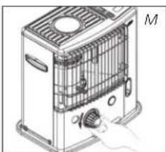
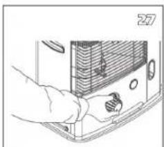
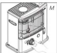
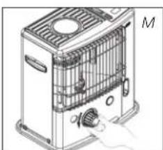
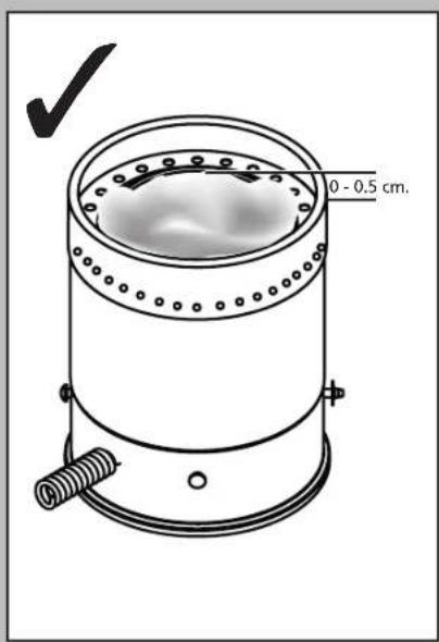
After you have ignited the heater, it will take 10 to 15 minutes before you can check whether the heater is burning well. Too high a flame may cause smoke and soot, whereas too low a flame causes smells. Fig. Q shows the minimum and maximum permissible burning heights of the flame. The flame can be slightly adjusted with the knurled wick adjustment knob ② (Fig. M).

Burning that is too low may be caused by:

▶ insufficient fuel (fill the tank)
▶ poor fuel quality (contact your dealer)
▶ insufficient ventilation (put window or door ajar)
▶ wastage of the wick (contact your dealer or replace the wick, refer to section L

E SWITCHING OFF THE HEATER

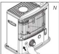
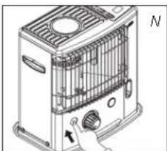
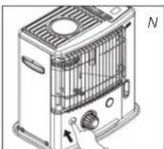
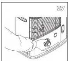
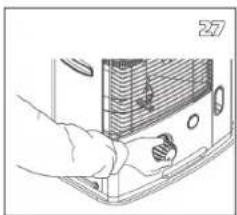
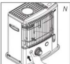
Push the OFF-button ①. The flame will extinguish after a little while (Fig. N).

F MALFUNCTION, CAUSES AND SOLUTIONS

If any malfunctioning cannot be solved from the directions below, please contact your dealer.

THE HEATER DOES NOT IGNITE

▶ The batteries are not positioned correctly in the holder. Check (Fig. G).
There is not enough power left in the batteries for the ignition. Replace (Fig. G).
▶ You have run out of fuel from the tank or the wick has been replaced. After having refilled and replaced the removable tank, wait for 30 minutes before igniting the heater.
▶ You are pushing the ignition button ③ with too much force. Push it in less forcefully (Section C).
▶ The ignition coil ⑪ is defective. Contact your dealer.

GB

69
Technical line drawing of a door panel with mounting holes and a label 'G' (no text or symbols on the diagram itself)

IRREGULAR FLAME AND/OR SOOT AND/OR SMELLS

▶ The combustion chamber ④ has not been positioned correctly.
Use the handle ⑤ to put it level, until you can easily slide it slightly to the left and to the right and the chamber is level.
▶ You are using fuel which is past its 'use by' date.
Start every heating season with fresh fuel.
▶ You are using the incorrect type of fuel.
Refer to THE RIGHT FUEL (See Section 'What you need to know in advance').
▶ Dust has gathered in the lower part of the heater.
Contact your dealer.
▶ The wick height is not correct.
Contact your dealer.

THE HEATER SLOWLY EXTINGUISHES

▶ The removable tank is empty.
See Section B.
▶ The lower reservoir is contaminated by moist.
Contact your dealer.
▶ The wick has hardened on the upper side.
Burn the heater until all fuel is used (Section G). Use the right fuel.
▶ You are using fuel which is past its 'use by' date.
Start every heating season with fresh fuel.

THE HEATER REMAINS BURNING LOW

▶ Wick position too low.
Contact your dealer.
▶ Before you refilled the tank, the heater had burnt up almost all the fuel.
After having refilled and replaced the removable tank, wait for 30 minutes before igniting the heater.
▶ You are using the incorrect type of fuel.
Refer to THE RIGHT FUEL (See Section 'What you need to know in advance').
▶ The room is insufficiently ventilated.
Leave a window or a door wide open for a while.

THE HEATER IS BURNING TOO HIGH

▶ You are using an incorrect, too volatile type of fuel.
Refer to THE RIGHT FUEL (See Section 'What you need to know in advance').
▶ Wick position too high.
Contact your dealer.

QLIMA R133TC - THE HEATER IS BURNING TOO HIGH - 1

QLIMA R133TC - THE HEATER IS BURNING TOO HIGH - 2
ignition coil

G MAINTENANCE

Your heater needs hardly any maintenance. It is, however, important that you remove dust and stains in time with a damp cloth, because otherwise these may cause stains that are hard to remove. Under normal conditions, only three components are subject to wear:

1. THE BATTERIES

You may replace the batteries yourself. Do not dispose of old batteries along with the other domestic waste. Follow the locally applicable regulations regarding the disposal of domestic chemical waste. - Do not throw batteries into the fire, where they can explode or release dangerous liquids.

2. THE IGNITION COIL

The ignition coil will have a longer life, if you ignite the heater in the correct manner. Replace the batteries in time and take care not to push in the ignition button with too much force. If the filament is broken, the ignition coil must be replaced.

GB

70

QLIMA R133TC - THE IGNITION COIL - 1

QLIMA R133TC - THE IGNITION COIL - 2

3. THE WICK

To extend the glass fibre wick life, you must occasionally let the heater burn until the tank is completely emptied and the heater extinguishes by itself. Do this when you notice that the flame is weakening. The burn-out will cause some smells, so it is recommended that you take the heater outside of the living room.

QLIMA R133TC - THE WICK - 1

Do not remove any heater components yourself. Always contact your dealer for repairs.

QLIMA R133TC - THE WICK - 2

Let the heater cool down first, before you start any maintenance or service work.

H STORAGE (END OF THE HEATING SEASON)

We recommend that you burn up all the fuel in the fuel tank at the end of the heating season and store the heater properly. Follow the procedure on the next page:

1 Ignite the heater outside the living room and let it burn until all fuel is used.
2 Let the heater cool down.
3 Clean the heater with a damp cloth and then dry it with a dry cloth.
4 Remove the batteries from the holder ⑫ and store them in a dry place.
5 Clean the fuel filter.
6 Store the heater in a dust-free place, if possible in its original packaging. Unused fuel cannot be used for the next heating season. If there is still some fuel left, do not throw it away, but dispose of it in accordance with the local regulations for the disposal of domestic chemical waste. Always start the new heating season with fresh fuel. When you start re-using the heater, follow the instructions again (starting from Section A and as specified).
Simple line drawing of a mortar or pestle with a handle and base (no text or symbols)

transportation cap

TRANSPORTATION

Take the following measures to avoid fuel leakage during the transportation of the heater:

1 Let the heater cool down.
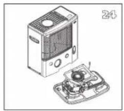
2 Remove the removable tank ⑨ from the heater and remove the fuel filter. Some drops may leak from the filter; keep a cloth at hand. Store the fuel filter and the removable tank outside the heater.
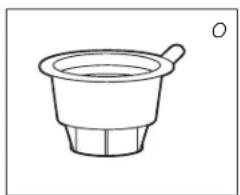
3 Place the transportation cap (Fig. O) into the position of the fuel filter. Press it tight. The transportation cap will, as much as possible, prevent oil leakage from the heater during transport.
4 Always move the heater in an upright position.

5 Make the fixed tank empty with a fuel pump before transportation or in case of wrong or dirty fuel. First remove the fuel filter and then insert the fuel pump into the empty fixed tank. Follow the same procedure if the fuel tank contains water.

GB

71

J SPECIFICATIONS

R 133 TC
Ignition electrical
Fuel paraffin
Capacity (kW)* 2.3
Suitable space (m3)** 37-82
Fuel consumption (l/hr)* 0.240
Fuel consumption (g/hr)* 192
Burning time per tank (hr)* 17.5
Capacity removable tank (litres) 4.2
Weight (kg) 8.5
Dimensions (mm) (including base plate)width 455
depth 295
height 460
Required batteries 3V D.C. (R20 x 2)
Wick type N

* At maximum setting
** Specified values are indicative

K WARRANTY PROVISIONS

Your heater comes with a 24-month warranty starting on the date of purchase. Within this period all defects in material or workmanship will be repaired without any charge. The following provisions shall apply regarding this warranty:

1 We expressly dismiss all other claims for damages, including consequential damages.
2 Any repairs or replacements of components within the term of warranty will not result in an extension of the term of warranty.
3 The warranty will no longer apply, when the heater has been modified, non-original parts have been used, or when it is repaired by third parties.
4 The warranty will not apply to parts that are subject to normal wear, such as the batteries, the ignition coil, the wick and the manual fuel pump.
5 The warranty will only apply, when you present the original, dated proof of purchase, provided no changes have been made to it.
6 The warranty will not apply to damages caused by actions not in compliance with the Directions for Use, neglect, and the use of an incorrect type of fuel, or fuel past its use-by date. The use of incorrect fuel can even be dangerous*.
7 Transportation costs and the risks involved during the transportation of the heater or heater components will always be the responsibility of the purchaser.

In order to avoid unnecessary costs, we recommend that you always read the 'Directions for Use' carefully first. In case they offer no solution, please take the heater to your dealer for repair.

* Highly inflammable substances may induce uncontrollable burning, causing flames to break out. Should this happen, never try to move the heater, but always switch off the heater immediately (refer to Section E). In cases of emergency you may use a fire extinguisher, but only a type B extinguisher: a carbon dioxide or powder extinguisher.

QLIMA R133TC - K WARRANTY PROVISIONS - 1

100cm 20cm 50cm 50cm 150cm

14 TIPS FOR SAFE USE

1 Children should be supervised to ensure that they do not play with the appliance.
2 Do not move the heater when it is burning or still hot. Do not refill nor service the heater when it is burning or still hot.
3 Position the front of the heater at a minimum distance of 1.5 metres from walls, curtains, and furniture.
4 Do not use the heater in dusty rooms or in very draughty places. In both cases you will not have optimum burning.
5 Switch off the heater, before you go to sleep.
6 Store and move fuel only in suitable tanks and jerrycans.
7 Make sure that the fuel is not exposed to heat or extreme temperature changes. Always store the fuel in a cool, dry and dark place (sunlight will affect the quality).
8 Never use the heater in places where harmful gasses or fumes may be present (e.g. exhaust gasses or paint fumes).
9 Be aware that the grid of the heater becomes hot. If the appliance is covered there is a risk of fire.
10 Always make sure that there is sufficient ventilation.
11 This appliance is not intended for use by persons (including children) with reduced physical, sensory or mental capabilities, or lack of experience and knowledge, unless they have been given supervision or instruction concerning use of the appliance by a person responsible for their safety.
12 This appliance can be used by children aged from 8 years and above and persons with reduced physical, sensory or mental capabilities or lack of experience and knowledge if they have been given supervision or instruction concerning use of the appliance in a safe way and understand the hazards involved.
13 Children shall not play with the appliance.
14 Cleaning and user maintenance shall not be made by children without supervision.

Illustration of a portable electronic device with a handle and control panel (no text or symbols visible)

Illustration of a hand inserting a heater into a door panel, showing internal components and wiring (no text or symbols)

Technical illustration of a device with an open lid and internal components (no text or symbols)

Technical line drawing of a mechanical device with no visible text or symbols

Technical line drawing of a mechanical device with labeled parts A and B (no text or symbols beyond labels)

Line drawing of a mechanical device with a central component and wiring (no text or symbols)

Mechanical component diagram showing a cylindrical assembly with an arrow indicating direction (no text or symbols)

Technical line drawing of a mechanical device with a cylindrical component and a rectangular base (no text or symbols)

Diagram illustrating a cooking process with labeled steps: boiling, heating, and drying.

Mechanical assembly diagram showing a hand operating a rotating component with a spring and lever (no text or symbols)

Line drawing of a hand holding a curled-up, segmented object (no text or symbols)

Line drawing of a mechanical device with a cylindrical component and a base, no text or symbols present

Technical line drawing of a mechanical component with no visible text or symbols

Technical line drawing of a mechanical component (no text or symbols visible)

REPLACEMENT OF THE WICK

L ENSURE THAT THE HEATER IS OFF AND COMPLETELY COOL BEFORE STARTING TO REPLACE THE WICK.

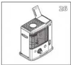
1a. Open the tank cover ⑧ and remove the fuel tank ⑨.

1b. Remove the batteries to prevent possible burns.

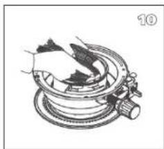
1c. Open the front grille and remove the combustion chamber ④.

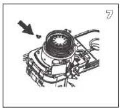
1d. Remove the knurled wick adjustment knob ② by pulling it straight out.

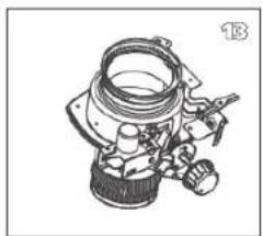
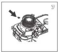
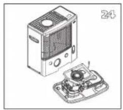
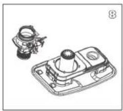
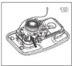
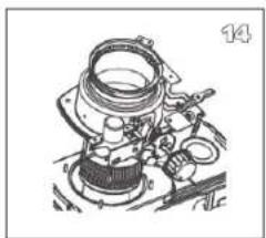
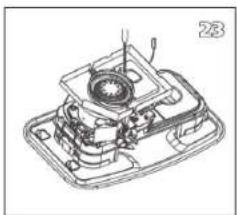
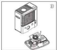
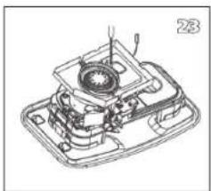
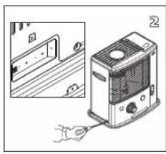
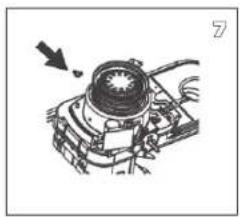
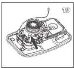
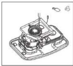
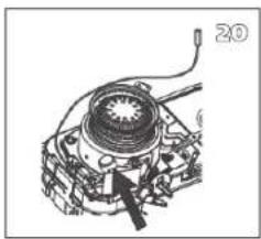
2a. Unscrew the 5 screws, 1 from the back and 2 from the right side and 2 from the left side of the cabinet 14.

2b. Remote the sensor at the back side of the cabinet 14.

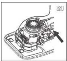
  1. Remove the cabinet by pulling it straight up.

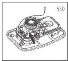
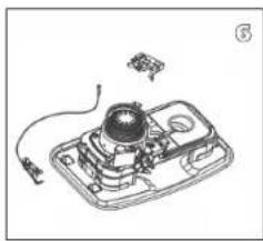
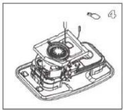
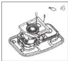
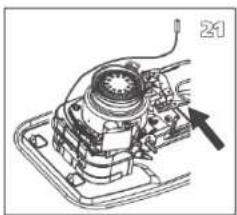
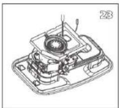
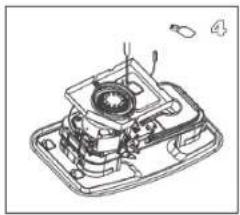
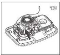
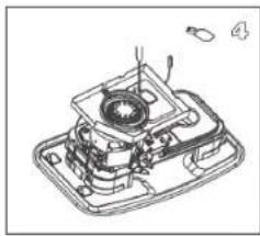
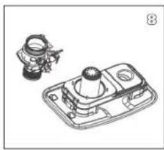
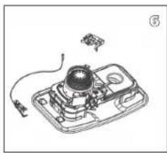
  2. Remove the 2 screws on the ignitor coil ⑪.

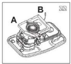
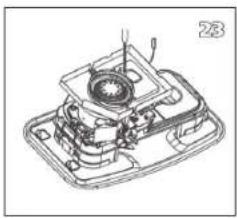
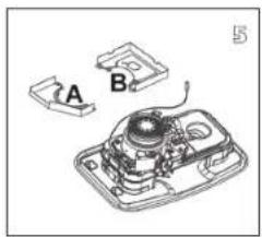
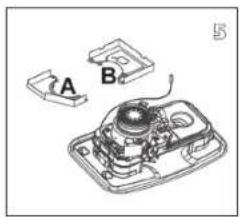
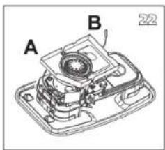
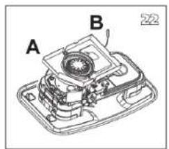
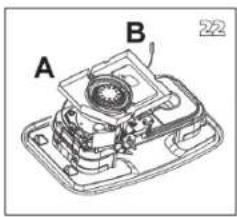
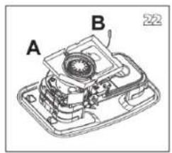
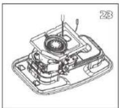
  3. Remove the wind cover A/B.

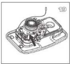
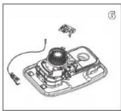
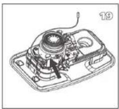
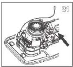
6a. Remove the automatic ignition assembly by unscrewing 1 screw.

6b. Remove the tip-over safety mechanism by unscrewing 2 screws.

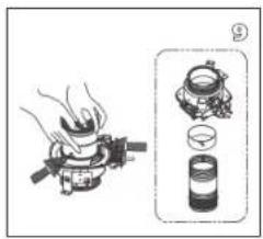
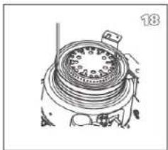
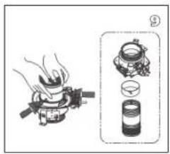
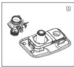
  1. Unscrew 4 wing nuts.

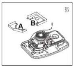
  2. Remove the wick adjuster assembly.

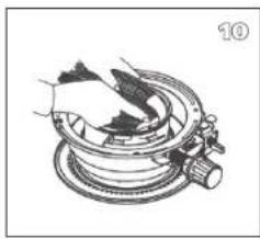
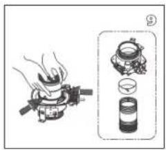
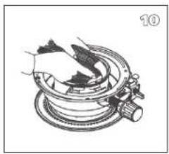
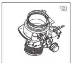
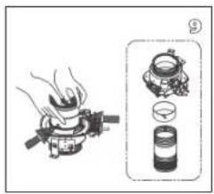
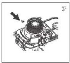
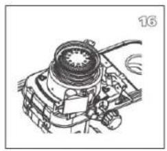
  3. Press the pin of the wick which is assembled inside the wick case assembly. Disassemble the wick, the wick holder, the wick case assembly separately.

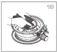
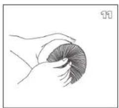
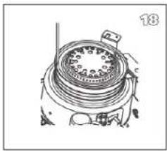
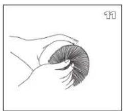
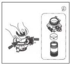
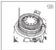
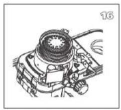
  4. Install the new wick and insert the three pins on the new wick into the 3 holes on the wick sleeve in the upward direction (See the arrow marked "up" on the wick sleeve).

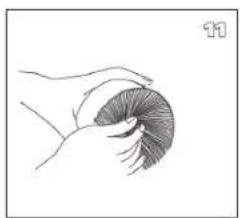
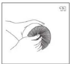
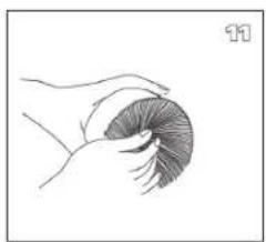
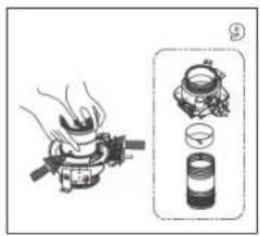
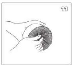
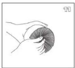
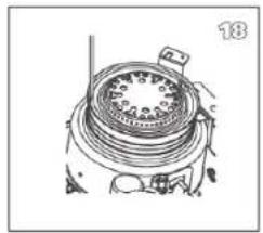
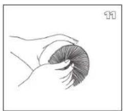
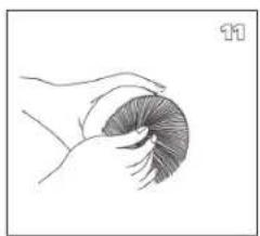
  5. Push the new wick into the retainer teeth of the wick sleeve so that the wick adheres tightly around the inside of the wick sleeve, smoothly without any wrinkles.

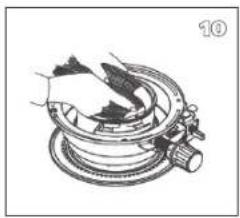
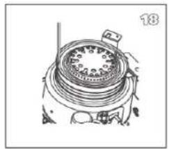
  6. Line up the pins with the slotted holes inside the wick adjuster. Then lightly press each of the three pins of the wick (now attached to the wick sleeve) towards the inside. Insert the three pins into the slanted grooves of the wick adjuster. Press on each of the three pins, inserting them securely in the holes.

  7. Turn the knurled wick adjustment knob ② and check to be sure that the wick moves up and down freely.

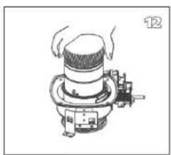
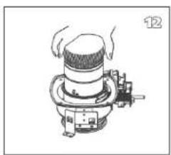
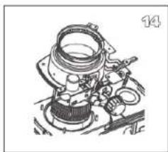
  8. Slide the wick adjuster assembly down the draft tube. Position the adjuster shaft to the front of the heater.

GB

74

Mechanical assembly diagram showing a fan or gear mechanism with a downward arrow indicating motion (no text or symbols present)

Technical line drawing of a mechanical assembly with no visible text or symbols

5/16" 17

Technical line drawing of a mechanical component with no visible text or symbols

Technical line drawing of a mechanical device with no visible text or symbols

Technical line drawing of a mechanical clutch assembly (no text or symbols)

Technical line drawing of a mechanical device with no visible text or symbols

A B 22

Technical line drawing of a mechanical device with no visible text or symbols

Technical illustration of a device with a front-mounted unit and internal components (no text or symbols)

Illustration of a portable air conditioner unit connected to a hand holding a tool, with an inset showing a door opening (no text or symbols visible)

Line drawing of a portable electronic device with ventilation slots and a handle (no text or symbols)

Line drawing of a hand pressing down on a device panel (no text or symbols visible)

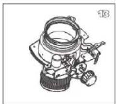
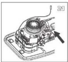
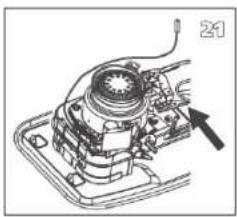
  1. Reposition 4 wing nuts on the mounting stud, but do not tighten them.
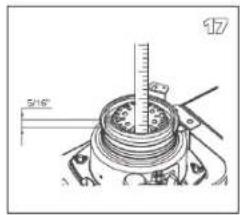
  2. Raise the wick to its highest position and tighten the wing nuts in several steps.
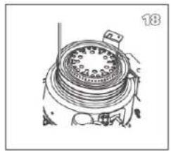
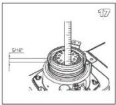
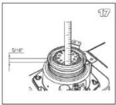
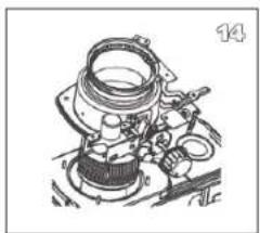
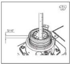
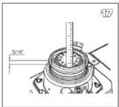
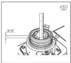
  3. Check the wick height. It should be 5/16 inch above the collar.
  4. Check for the correct clearance between wick holder and draft tube. It should be the same all around.
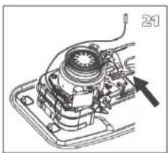
  5. Reinstall the tip-over switch assembly by pushing the extinguish knob ①.
  6. Check the function of the tip-over safety stop by pushing the extinguish button ① to activate the pendulum.
  7. Reinstall the automatic ignition assembly.
  8. Reinstall the wind cover A / B.
  9. Reinstall the ignitor coil ⑪.
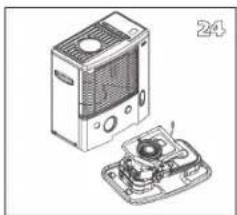
  10. Reinstall the cabinet 14.
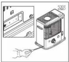
  11. Tighten the 5 screws on the cabinet and reinstall the sensor at the back of the cabinet ⑭.
  12. Reinstall the combustion chamber ④ and the fuel tank ⑨.
  13. Reinstall the knurled wick adjustment knob ②. Close the front plate.

Install the batteries in the battery case and fill the fuel tank with Premium Quality Fuels. Put the tank into the heater and wait at least 30 minutes for the new wick to fully saturate with the fuel.

Egregio Signore, Gentile Signora,
Technical line drawing of a mechanical housing or enclosure with internal components and directional arrows (no text or symbols)

Technical line drawing of a mechanical device with no visible text or symbols

Illustration of a kitchen appliance with fan, stove, and oven (no text or symbols)

MANUALE

QLIMA R133TC - MANUALE - 1

C ACCENSIONE DELLA STUFA

QLIMA R133TC - C ACCENSIONE DELLA STUFA - 1

Diagram of a hand using a tool to adjust or install a component on a device (no text or symbols visible)

Line drawing of a portable air conditioner unit with handle and ventilation slots (no text or symbols)

Illustration of a portable air conditioner unit with control panel and indicator lights (no text or symbols)

QLIMA R133TC - C ACCENSIONE DELLA STUFA - 5

D LA COMBUSTIONE DELLA STUFA

QLIMA R133TC - D LA COMBUSTIONE DELLA STUFA - 1

FIAMMA INCOSTANTE E/O FULIGGINE E/O CATTIVO ODORE.

2. LA RESISTENZA DI ACCENSIONE

Illustration of a hand inserting a heater into a door panel, showing internal components and wiring (no text or symbols)

Technical illustration of a device with an open lid and internal components (no text or symbols)

Technical line drawing of a mechanical device with no visible text or symbols

Technical line drawing of a mechanical device with labeled parts A and B (no text or symbols beyond labels)

Line drawing of a mechanical device with a central component and wiring (no text or symbols)

Mechanical component diagram showing a cylindrical assembly with an arrow indicating direction (no text or symbols)

Technical line drawing of a mechanical device with a cylindrical component and a base tray (no text or symbols)

Diagram illustrating a cooking process with labeled steps: boiling, heating, and pouring into a container.

Mechanical assembly diagram showing a hand operating a rotating component with a spring and lever (no text or symbols)

Hand holding a circular object with radial lines, resembling a stylized worm or gear (no text or symbols)

Line drawing of a mechanical device with hands and a knob, no text or symbols present

Technical line drawing of a mechanical component (no text or symbols)

Technical line drawing of a mechanical component with no visible text or symbols

Technical line drawing of a mechanical assembly with no visible text or symbols

5/16" 17

Technical line drawing of a mechanical component with concentric rings and a central hub (no text or symbols)

Technical line drawing of a mechanical device with no visible text or symbols

Technical line drawing of a mechanical component with no visible text or symbols

Technical line drawing of a mechanical device with no visible text or symbols

A B 22

Technical line drawing of a mechanical device with no visible text or symbols

Technical illustration of a device with internal components and a separate housing (no text or symbols)

Illustration of a portable air conditioner unit connected to a hand holding a tool, with an inset showing a door opening (no text or symbols visible)

Line drawing of a portable electrical device with ventilation slots and a handle (no text or symbols)

Line drawing of a hand pressing down on a device component (no text or symbols visible)

② Riflet regulerings-bryter

③ Tenningsknapp

4 Forbrenningskammer

HÅNDBOK

QLIMA R133TC - HÅNDBOK - 1

A INSTALLERE OVNEN

Technical line drawing of a portable air conditioner unit with labeled component B (no text or symbols beyond label)

Technical line drawing of a mechanical device with no visible text or symbols

Technical line drawing of a kitchen appliance with fan, vent, and cooling unit (no text or symbols)

1 2 3

C TENNE VARMEOVNEN

OVNEN SLÅR SEG LANGSOMT AV

transportdeksel

H OPPBEVARING (SLUTT PÅ DEN KALDE ÅRSTIDEN)

Illustration of a hand inserting a heater into a door panel, showing internal components and wiring (no text or symbols)

Technical illustration of a device with an open lid and internal components (no text or symbols)

Technical line drawing of a mechanical device with no visible text or symbols

Technical line drawing of a mechanical device with labeled parts A and B (no text or symbols beyond labels)

Line drawing of a mechanical device with a central component and wiring (no text or symbols)

Mechanical component diagram showing a cylindrical assembly with an arrow indicating direction (no text or symbols)

Technical line drawing of a mechanical device with a cylindrical component and a rectangular base (no text or symbols)

Diagram illustrating a cooking process with labeled steps: boiling, heating, and drying.

Mechanical assembly diagram showing a hand operating a rotating component with a spring and lever (no text or symbols)

Line drawing of a hand holding a curled-up, segmented object (no text or symbols)

Line drawing of a mechanical device with a cylindrical component and base, no text or symbols present

Technical line drawing of a mechanical component with no visible text or symbols

Technical line drawing of a mechanical component (no text or symbols visible)

SKIFTE UT VEKEN

L PASS PÅ AT OVNEN ER AV OG HELT KALD F∅R DU BEGYNNER Å BYTTE VEKEN.

Technical line drawing of a mechanical assembly with no visible text or symbols

5/16" 17

Technical line drawing of a mechanical component with no visible text or symbols

Technical line drawing of a mechanical device with no visible text or symbols

Technical line drawing of a mechanical clutch assembly (no text or symbols)

Technical line drawing of a mechanical device with no visible text or symbols

A B 22

Technical line drawing of a mechanical device with no visible text or symbols

Technical illustration of a device with a front-mounted unit and internal components (no text or symbols)

Illustration of a portable air conditioner unit connected to a hand holding a tool, with an inset showing a door opening (no text or symbols visible)

Line drawing of a portable electronic device with ventilation slots and a handle (no text or symbols)

Line drawing of a hand pressing down on a device panel (no text or symbols visible)

WAT U VOORAF MOET WETEN

ALTIJD VOLDOENDE VENTILEREN
Technical line drawing of a mechanical device with internal components and directional arrows (no text or symbols)

Technical line drawing of a kitchen appliance with fan, stove, and oven (no text or symbols)

Exploded view diagram of a microwave oven assembly with labeled components and directional arrows indicating assembly steps.

HANDLEIDING

QLIMA R133TC - HANDLEIDING - 1

A HET INSTALLEREN VAN DE KACHEL

Diagram of a hand operating a mechanical device with a mesh component and directional arrows (no text or symbols)

Technical line drawing of a door panel with mounting holes and a label 'G' (no readable text or symbols)

Diagram of a mechanical device with a labeled component H, showing internal components and an upward arrow (no text or symbols present)

Diagram of a water storage bottle connected to a gas bag with a connecting rod (no text or symbols)

1 2 3

NL

104

Technical line drawing of a portable air conditioner unit with ventilation grilles and control panel (no text or symbols)

Illustration of a portable air conditioner unit with a hand operating the control panel (no text or symbols visible)

C HET AANMAKEN VAN DE KACHEL

F STORINGEN, OORZAKEN EN OPLOSSINGEN

Transportdop

Illustration of a portable electric heater with a hand inserting a plug, shown alongside an inset view of its door panel (no text or symbols present)

Technical illustration of a device with an open lid and internal components (no text or symbols)

Technical line drawing of a mechanical assembly with gears and components (no text or symbols)

Technical line drawing of a mechanical device with labeled parts A and B (no text or symbols beyond labels)

Line drawing of a handheld device with a central hub and wiring (no text or symbols)

Mechanical component diagram showing a cylindrical assembly with an arrow indicating direction (no text or symbols)

Technical line drawing of a mechanical device with a cylindrical component and a base plate (no text or symbols)

Diagram illustrating a cooking process with labeled steps: boiling, heating, and drying.

Mechanical assembly diagram showing a hand holding a component over a circular housing (no text or symbols visible)

Line drawing of a hand holding a curled-up, segmented object (no text or symbols)

Illustration of a mechanical device with hands operating it, no visible text or symbols

Technical line drawing of a mechanical component with no visible text or symbols

Technical line drawing of a mechanical component (no text or symbols visible)

HET VERVANGEN VAN DE KOUS

L VOORDAT U BEGINT MET HET VERVANGEN VAN DE KOUS, DIENT DE KACHEL UIT EN VOLLEDIG AFGEKOELD TE ZIJN.

Technical line drawing of a mechanical assembly with no visible text or symbols

5/16" 17

Technical line drawing of a mechanical component with concentric rings and a central hub (no text or symbols)

Technical line drawing of a mechanical device with no visible text or symbols

Technical line drawing of a mechanical clutch assembly (no text or symbols)

Technical line drawing of a mechanical assembly with no visible text or symbols

A B 22

Technical line drawing of a mechanical device with no visible text or symbols

Illustration of a device with an open lid and internal components, no visible text or symbols

Illustration of a hand inserting a plug into a device labeled '25', with an inset showing a door panel (no text or symbols on the device itself)

Technical line drawing of a mechanical device with a handle and internal components (no text or symbols)

Line drawing of a hand operating a device with a knob (no text or symbols)

MANUAL

Technical line drawing of a mechanical housing or enclosure with internal components and directional arrows (no text or symbols)

Technical line drawing of a mechanical device with no visible text or symbols

Diagram of a kitchen appliance showing fan, stove, and oven with a side panel (no text or labels)

Diagram of a hand using a tool to adjust or install a component on a shelf, with no visible text or symbols.

Technical line drawing of a door panel with mounting holes and a label 'G' (no text or symbols beyond basic diagram)

Diagram of a mechanical device with a labeled component H, showing internal components and a directional arrow (no text or symbols beyond label)

1 2 3

C ACENDER O AQUECEDOR

Technical line drawing of a portable air conditioner unit with labeled ports (no text or symbols beyond 'M')

Illustration of a portable air conditioner unit with a hand operating the fan (no text or symbols visible)

Tampa de transporte
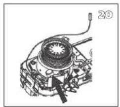
Illustration of a portable air conditioner unit with a hand inserting a cable (no text or symbols visible)

Technical illustration of a device with an open lid and internal components (no text or symbols)

Technical line drawing of a mechanical device with no visible text or symbols

Technical line drawing of a mechanical device with labeled parts A and B (no text or symbols beyond labels)

Line drawing of a mechanical device with a central component and wiring (no text or symbols)

Mechanical component diagram showing a cylindrical assembly with an arrow indicating direction (no text or symbols)

Technical line drawing of a mechanical device with a cylindrical component and a rectangular base (no text or symbols)

Diagram illustrating a cooking process with labeled steps: boiling, heating, and drying.

Mechanical assembly diagram showing a hand operating a rotating component with a spring and valve (no text or symbols)

Simple line drawing of a hand holding a curled-up, no text or symbols present

Line drawing of a mechanical device with a cylindrical top and base, emitting motion lines (no text or symbols)

Technical line drawing of a mechanical component with no visible text or symbols

Technical line drawing of a mechanical component (no text or symbols visible)

Technical line drawing of a mechanical assembly with no visible text or symbols

5/16" 17

Technical line drawing of a mechanical clutch assembly (no text or symbols)

Technical line drawing of a mechanical device with no visible text or symbols

Technical line drawing of a mechanical component with no visible text or symbols

Technical line drawing of a mechanical assembly with no visible text or symbols

A B 22

Technical line drawing of a mechanical device with no visible text or symbols

Technical illustration of a device with internal components and a base housing (no text or symbols)

Illustration of a hand inserting a plug into a device labeled '25', with an inset showing a door panel (no text or symbols on the device itself)

Illustration of a portable electronic device with ventilation slots and a handle (no text or symbols)

Line drawing of a hand operating a device with a knob (no text or symbols)

ZAPEWNIĆ ODPOWIEDNIA WENTYLACJE,

INSTRUKCJA OBSŁUGI

QLIMA R133TC - INSTRUKCJA OBSŁUGI - 1

A INSTALACJA GRZEJNIKA

Technical line drawing of a mechanical housing or enclosure with internal components and directional arrows (no text or symbols)

Technical diagram of a mechanical device with pressure gauges and control knobs (no text or labels)

Diagram of a kitchen appliance showing a fan, stove, and oven with a side view (no text or labels)

1 2 3

Technical line drawing of a mechanical assembly with no visible text or symbols

Technical line drawing of a portable air conditioner unit with ventilation grilles and control panel (no text or symbols)

Illustration of a portable air conditioner unit with a hand operating the front panel (no text or symbols visible)

D REGULOWANIE PŁOMIENIA

GRZEJNIK POWOLI SAMOCZYNNIE WYGASA

korek transportowy

J PARAMETRY TECHNICZNE

Illustration of a hand inserting a heater into a door panel, showing internal components and wiring (no text or symbols)

Technical illustration of a device with an open lid and internal components (no text or symbols)

Technical line drawing of a mechanical device with no visible text or symbols

Technical line drawing of a mechanical device with labeled parts A and B (no text or symbols beyond labels)

Line drawing of a mechanical device with a central component and wiring (no text or symbols)

Mechanical component diagram showing a cylindrical assembly with an arrow indicating direction (no text or symbols)

Technical line drawing of a mechanical device with a cylindrical component and a rectangular base (no text or symbols)

Diagram illustrating a cooking process with labeled steps: boiling, heating, and drying.

Mechanical assembly diagram showing a hand operating a rotating component with a spring and lever (no text or symbols)

Simple line drawing of a hand holding a curled-up, no text or symbols present

Line drawing of a mechanical device with a cylindrical top and base, emitting motion lines (no text or symbols)

Technical line drawing of a mechanical component with no visible text or symbols

Technical line drawing of a mechanical component (no text or symbols visible)

WYMIANA KNOTA

L ZANIM ROZPOCZNIESZ WYMIANE KNOTA UPEWNIJ SIE, ŻE GRZEJNIK JEST WYŁĄCZONY I ZIMNY.
Technical line drawing of a mechanical assembly with no visible text or symbols

5/16" 17

Technical line drawing of a mechanical clutch assembly (no text or symbols)

Technical line drawing of a mechanical device with no visible text or symbols

Technical line drawing of a mechanical component with no visible text or symbols

Technical line drawing of a mechanical assembly with no visible text or symbols

A B 22

Technical line drawing of a mechanical device with no visible text or symbols

Technical illustration of a device with internal components and a separate open base (no text or symbols)

Illustration of a hand inserting a plug into a device labeled '25', showing internal components and wiring (no text or symbols present)

Illustration of a portable electronic device with ventilation slots and a handle (no text or symbols)

Line drawing of a hand operating a device with a knob (no text or symbols visible)

SE ALLTID TILL ATT DET FINNS TILLRÄCKLIG VENTILATION

MANUAL

QLIMA R133TC - MANUAL - 1

A INSTALLERA VÄRMAREN

Technical line drawing of a mechanical device with no visible text or symbols

Technical line drawing of a kitchen appliance with fan, sink, and ventilation unit (no text or symbols)

Line drawing of a fire extinguisher with a water bag attached, showing internal compartments and a handle (no text or symbols)

1 2 3

C TÄNDA VÄRMAREN

Technical line drawing of a portable air conditioner unit with ventilation grilles and control panel (no text or symbols)

Line drawing of a portable air conditioner unit with a hand operating the control panel (no text or symbols)

D VÄRMARENS FÖRBRÄNNING

VÄRMAREN FORTSÄTTER ATT BRINNA SVAGT

transportdeksel

J SPECIFICATIONER
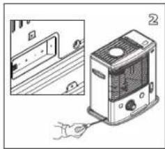
Illustration of a hand inserting a heater into a door panel, showing internal components and wiring (no text or symbols)

Technical illustration of a device with an open lid and internal components (no text or symbols)

Technical line drawing of a mechanical device with no visible text or symbols

Technical line drawing of a mechanical device with labeled parts A and B (no text or symbols beyond labels)

Line drawing of a mechanical device with a central component and wiring (no text or symbols)

Mechanical component diagram showing a cylindrical assembly with an arrow indicating direction (no text or symbols)

Technical line drawing of a mechanical device with a cylindrical component and a rectangular base (no text or symbols)

Diagram illustrating a cooking process with labeled steps: boiling, heating, and drying.

Mechanical assembly diagram showing a hand operating a rotating component with a spring and lever (no text or symbols)

Simple line drawing of a hand holding a curled-up, no text or symbols present

Line drawing of a mechanical device with a cylindrical top and base, emitting motion lines (no text or symbols)

Technical line drawing of a mechanical component with no visible text or symbols

Technical line drawing of a mechanical component (no text or symbols visible)

BYTE AV VEKEN

L KONTROLLERA ATT VÄRMAREN ÄR AVSTÄNGD OCH HELT AVSVALNAD INNAN DU BYTER VEKE.

Technical line drawing of a mechanical assembly with no visible text or symbols

5/16" 17

Technical line drawing of a mechanical clutch assembly (no text or symbols)

Technical line drawing of a mechanical device with no visible text or symbols

Technical line drawing of a mechanical component with no visible text or symbols

Technical line drawing of a mechanical assembly with no visible text or symbols

A B 22

Technical line drawing of a mechanical device with no visible text or symbols

Technical illustration of a device with internal components and a base housing (no text or symbols)

Illustration of a hand inserting a plug into a device labeled '25', with an inset showing a door panel (no text or symbols on the device itself)

Line drawing of a portable electronic device with ventilation slots and a handle (no text or symbols)

Line drawing of a hand operating a device with a knob (no text or symbols)

QLIMA R133TC - NAVODILA ZA UPORABO - 1

A PRIPRAVA PEČI

Technical line drawing of a portable air conditioner unit with labeled component B (no text or symbols beyond label)

Technical line drawing of a mechanical device with no visible text or symbols

Technical illustration of a kitchen appliance with fan, evaporator, and cooling unit (no text or symbols)

1 Previdno izvlecite peč iz embalaže in preverite vsebino kartonske škatle. Poleg peči morate imeti tudi:
▶ transportni pokrovček
▶ ta navodila za uporabo

Shranite embalažo (glej sliko A) za hranjenje in transport peči.

2 Odstranite ostale dele varovalnega materiala:
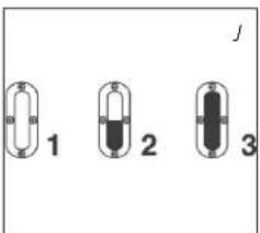
1 2 3

C PRIŽIGANJE PEČI

Technical line drawing of a portable air conditioner unit with labeled ports (no text or symbols beyond 'M')

Illustration of a portable air conditioner unit with a hand operating the fan (no text or symbols visible)

Technical line drawing of a door panel with buttons and a label 'G' (no readable text or symbols)

D DELOVANJE PEČI

Transportni pokrovček

Illustration of a portable electric heater with a hand inserting a cable (no text or symbols visible)

Technical illustration of a device with an open lid and internal components (no text or symbols)

Technical line drawing of a mechanical device with no visible text or symbols

Technical line drawing of a mechanical device with labeled parts A and B (no text or symbols beyond labels)

Line drawing of a mechanical device with a central component and wiring (no text or symbols)

Mechanical component diagram showing a cylindrical assembly with an arrow indicating direction (no text or symbols)

Technical line drawing of a mechanical device with a cylindrical component and a rectangular base (no text or symbols)

Diagram illustrating a cooking process with labeled steps: boiling, heating, and drying.

Mechanical assembly diagram showing a hand operating a rotating component with a spring and lever (no text or symbols)

Line drawing of a hand holding a curled-up, segmented object (no text or symbols)

Line drawing of a mechanical device with a cylindrical component and base, no text or symbols present

Technical line drawing of a mechanical component with no visible text or symbols

Technical line drawing of a mechanical component (no text or symbols visible)

MENJAVA STENJA

L PRED MENJAVO STENJA SE PREPRIČAJTE, DA JE, PEČ UGASNJENA IN HLADNA.

Technical line drawing of a mechanical assembly with no visible text or symbols

5/16" 17

Technical line drawing of a mechanical component with no visible text or symbols

Technical line drawing of a mechanical device with no visible text or symbols

Technical line drawing of a mechanical clutch assembly (no text or symbols)

Technical line drawing of a mechanical device with no visible text or symbols

A B 22

Technical line drawing of a mechanical device with no visible text or symbols

Technical illustration of a device with a front-mounted unit and internal components (no text or symbols)

Illustration of a portable air conditioner unit connected to a hand holding a tool, with an inset showing a door opening (no text or symbols visible)

Line drawing of a portable electronic device with ventilation slots and a handle (no text or symbols)

Line drawing of a hand pressing down on a device panel (no text or symbols visible)

0 - 0.5 cm.

Simple line drawing of a cylindrical container with a coiled spring and a lid, no text or symbols present.

Technical diagram of a multi-chamber air conditioner unit with numbered parts for identification

Mechanical component diagram showing a gear assembly with labeled part 11 (no text or symbols beyond label)

Technical line drawing of a mechanical device with labeled component (no text or symbols present)

www.pvg.eu

DISTRIBUTED IN EUROPE BY PVG Holding B.V.

⑥ Benötigen Sie weitere Informationen oder treten Probleme auf, besuchen Sie bitte unsere Website www.pvg.eu, oder setzen Sie sich mit unserem Kundendienst in Verbindung (Telefonnummer auf www.pvg.eu).
For alle yderligere oplysninger eller ved eventuelle problemer med apparatet henvises til PVG hjemmeside (www.pvg.eu) eller det lokale Kundecenter (telefonnumre findes i www.pvg.eu).
Si necesita información o si tiene algún problema, visite nuestra página Web www.pvg.eu, o póngase en contacto con el servicio cliente (hallará el número de teléfono en www.pvg.eu).
Si vous souhaitez obtenir des informations supplémentaires ou si vous rencontrez un problème, rendez-vous sur notre site Web (www.pvg.eu) ou contactez le notre service client (vous trouverez l'adresse et numéro de téléphone sur www.pvg.eu).
Hf: Jos haluat huoltoapua, lisätietoja tai laitteen kanssa tulee ongelmia, tutustu PVG verkkosivustoon osoitteessa www.pvg.eu tai kysy neuvoa PVG kuluttajapalvelukeskuksesta (www.pvg.eu).
(68) If you need information or if you have a problem, please visit the PVG website (www.pvg.eu) or contact our sales support (you find its phone number on www.pvg.eu)
Per informazioni e in caso di problemi, visitate il sito Web www.pvg.eu oppure contattate il Centro Assistenza Clienti (per conoscere il numero di telefono, consultate www.pvg.eu).
Hvis du trenger informasjon, eller hvis du har et problem med produktet, kan du gå til nettsidene www.pvg.eu. Alternativt kan du kontakte med PVG' forbrukertjeneste (telefonnummeret i www.pvg.eu).
Als u informatie nodig hebt of als u een probleem hebt, bezoek dan de PVG website (www.pvg.eu) of neem contact op met de afdeling sales support (adres en telefoon op www.pvg.eu).
② Se necessitar de informações ou se tiver problemas, visite o Web site www.pvg.eu ou contacte o Centro de Assistência (número de telefone o www.pvg.eu)
W przypadku problemów i w celu uzyskania szczegółowych informacji odwiedź stronę internetową firmy PVG dostępną pod adresem www.pvg.eu lub skontaktuj się z Centrum kontaktów PVG (www.pvg.eu)
③ Om du behöver service eller information eller har problem med apparaten kan du besöka www.pvg.eu eller kontakta PVG kundtjänst (du hittar telefonnumret på www.pvg.eu).
⑧ Ce želite dodatne informacije, obiščite spletno mesto podjetja PVG na naslovu www.pvg.eu ali pokličite na telefonsko (www.pvg.eu).
Daha fazla bilgiye ihtiyaç duyarsanız veya bir sorunla karşılaşırsanız, www.pvg.eu adresindeki PVG Internet sitesini ziyaret edin veya ülkenizde bulunan PVG müşteri merkeziyle iletişim kurun (telefon numarasını: www.pvg.eu).
Table of contents Click a title to access it
Manual assistant
Powered by Anthropic
Waiting for your message
Product information

Brand : QLIMA

Model : R133TC

Category : Frying Pan