
US2-PH61155 - Audio/video converter PHILIPS - Free user manual and instructions
Find the device manual for free US2-PH61155 PHILIPS in PDF.


| Product Type | Audio/Video Converter |
| Brand | Philips |
| Model | US2-PH61155 |
| Color | Black |
| Dimensions (L x W x H) | 10 cm x 6 cm x 2 cm |
| Weight | 200 g |
| Power Supply | 5 V DC via USB port (cable included) |
| Power Consumption | 2.5 W max |
| Video Inputs | 1 x HDMI, 1 x Composite AV (RCA) |
| Video Outputs | 1 x HDMI, 1 x VGA |
| Audio Inputs | 1 x Stereo RCA (Left/Right) |
| Audio Outputs | 1 x 3.5 mm Stereo Jack |
| Supported Video Formats | PAL, NTSC, 480p, 720p, 1080p |
| Maximum Resolution | 1920 x 1080 pixels |
| Main Functions | HDMI to AV conversion, AV to HDMI conversion, scaling, audio extraction |
| Care and Cleaning | Clean with a soft, dry cloth. Do not use liquid or abrasive products. |
| Safety | CE, RoHS certifications. Use only the provided adapter. |
| Spare Parts and Repairability | Repairability index: 8.5/10. Parts available from the manufacturer. |
| Box Contents | Converter, USB cable, HDMI cable, AV cable (RCA), user manual |
| Warranty | 2 years |
Frequently Asked Questions - US2-PH61155 PHILIPS
User questions about US2-PH61155 PHILIPS
0 question about this device. Answer the ones you know or ask your own.
Ask a new question about this device
Download the instructions for your Audio/video converter in PDF format for free! Find your manual US2-PH61155 - PHILIPS and take your electronic device back in hand. On this page are published all the documents necessary for the use of your device. US2-PH61155 by PHILIPS.
USER MANUAL US2-PH61155 PHILIPS
Video RF Modulator Owner's Manual
INTRODUCTION
Your Video RF Modulator is designed to convert the separate audio and video signals (from a video camera, computer, portable VCR, satellite receiver, DVD player, etc.) into normal VHF TV signals that you can see on any regular TV set.
Warning: For indoor use only; to reduce risk of fire or shock hazard, do not expose this product to rain or moisture.

CAUTION
RISK OF ELECTRIC SHOCK. DO NOT OPEN.

CAUTION: TO REDUCE THE RISK OF ELECTRIC SHOCK, DO NOT REMOVE COVER OR BACK. NO USER-SERVICEABLE PARTS INSIDE. REFER SERVICING TO QUALIFIED PERSONNEL.
This symbol is intended to alert you to the presence of uninsulated dangerous voltage within the RF Modulator's enclosure that might be of sufficient magnitude to constitute a risk of electric shock. Do not open the RF Modulator's case.

This symbol is intended to inform you that important operating and maintenance instructions are included in the literature accompanying this RF Modulator.
THE FCC WANTS YOU TO KNOW
This device complies with Part 15 of the FCC Rules Operation is subject to the following two conditions: (1) This device may not cause harmful interference, and (2) this device must accept any interference received, including interference that may cause undesirable operation.
Even under optimum conditions, your Video RF Modulator may cause undesirable interference. We suggest the following methods for trouble shooting
- Use an AC outlet that is not the same circuit as the receiver.
- Place the RF Modulator in a location further away from your receiver.
In the event that interference still occurs after the above steps have been taken, you are required by FCC regulations to discontinue use of this product.
Important Safety Information
- Before beginning installation of your Video RF Modulator read all instructions and follow exactly throughout the installation.
- After installation is complete, keep all instructions in a safe place so they may be referred to in the future if necessary.
- Please note the ideal environment for this device is on a hard flat surface away from all heat sources and moisture.
PARTS REQUIRED
You need the following items, not supplied with your Video RF Modulator, to connect it between a video input source (video game, video camera, satellite receiver, DVD player, etc.) and your TV.
PARTS REQUIRED continued
- Two 75-ohm coaxial cables with F-type connectors
- If your TV does not have a VHF 75-ohm F-connector, you will also need a 75-ohm-to-300-ohm matching transformer
- One video shielded cable with RCA Plugs and one audio (stereo) cable with RCA Plugs OR Dubbing Cable for VCR/DVD with RCA Plugs OR 3 shielded cables with RCA Plugs
- One S-Video cable
CONNECTIONS
Follow these steps to connect your RF Modulator:
- Connect an S-Video or video cable between the S-Video or video output jack on your video source and the RF ModulatoSsVIDEO IN or VIDEO IN jack.
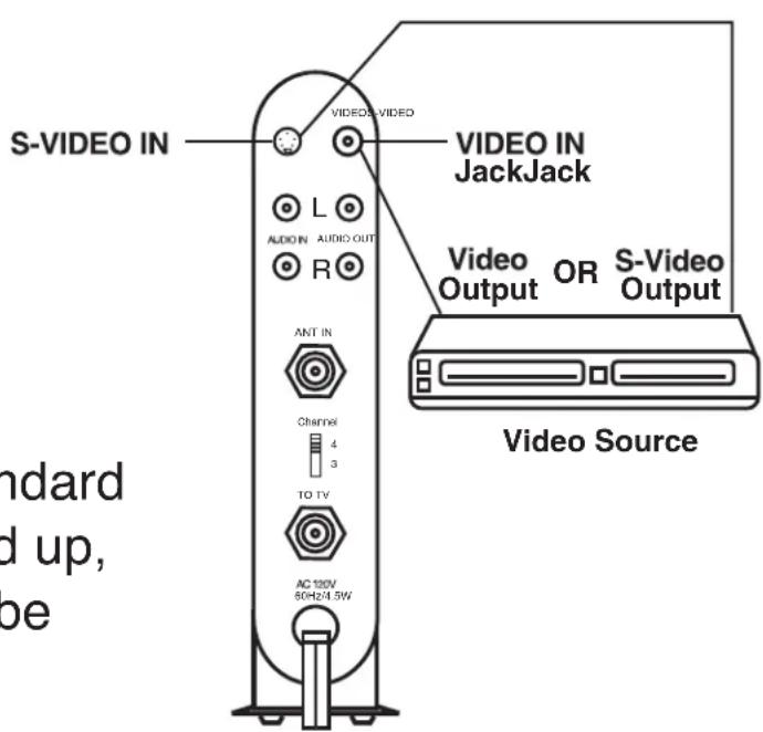
Note: If both the S-Video and standard video are hooked up, the S-Video will be given priority
CONNECTIONS continued
- Connect another audio/video cable between the audio output jacks on your video source and the RF Modulator AUDIO IN jacks.

- Connect the 75-ohm coaxial cables to the RF Modulator following these guidelines:
- If your TV is already connected to another VHF input source (such as cable TV, VCR, etc.):

CONNECTIONS continued
a. Disconnect the input sources 75-ohm cable from the TV's 75-ohm VHF input terminal, and reconnect it to the RF Modulator ANT IN terminal.
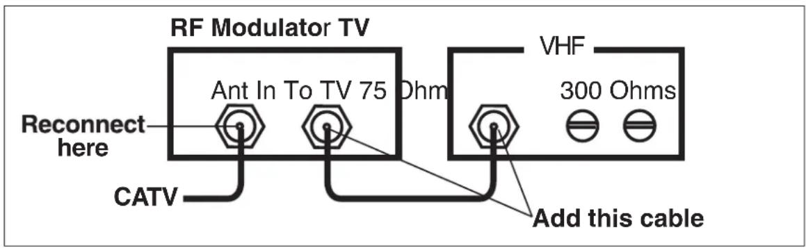
b. Then add a 75-ohm coaxial cable connected between the TO TV terminal on the RF Modulator and 75-ohm VHF input terminal on your TV.
- If your TV is not already connected to another VHF source:
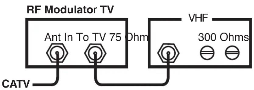
a. Connect the input sources (antenna, cable TV, VCR, etc.) 75-ohm cable to the RF Modulator's ANT IN terminal.
b. Connect a 75-ohm coaxial cable between the TO TV terminal on the RF Modulator and the 75-ohm VHF input terminal on your TV.
Note: If your TV has only 300-ohm VHF screw terminals, use a 75-ohm-to-300-ohm matching transformer to complete the connection.
- Plug the RF Modulator's power cord into a standard AC outlet.
OPERATION
- Turn on the TV and set it to either Channel 3 or 4, whichever of the two is not used for regular broadcasts in your area.
- Set the RF Modulator's CHANNEL 3 or 4 switch to the same channel you set on the TV (3 or 4)
- Turn on the connected video source, the modulator will deliver the video/audio signal to the TV set and light will switch to channel 3 or 4.
- Turn off the connected video source, the modulator will be switched automatically to deliver the ANT/Cable signal to the TV set and lights for channel 3 or 4 will turn off.
Note: LED light is on only while the video signal is being modulated

OPERATION continued
- To get stereo from your stereo receiver connect L-R stereo audio cables to stereo receiver or home theater.

SPECIFICATIONS
Video Carrier Output Level 63 dB uB dB uV
RF Output Channels 3 or 4 3 or 4
RF Output Impedance 75 ohms 75 ohms
Audio Input Impedance 13 13 ± 3 k ohms
Specifications are typical, individual units might vary.
Specifications are subject to change and improvement without notice.
Limited Lifetime Warranty the Manufacturer warrants that this product shall be free from defects in material, workmanship and assembly, under normal use, in accordance with the specifications and warnings, for the life of the product. This warranty extends only to the original purchaser and is non-transferable. Defective products must be returned with the dated proof of purchase to the place of purchase for replacement. THERE ARE NO OTHER EXPRESS OR IMPLIED WARRANTIES. Incidental or consequential damages are disclaimed where permitted by law.
PRECAUCIÓN
PELIGRO DE ELECTROCHOQUE NO ABRIR

CONNECTIONS continued
ATTENTION
RISQUE DE CHOC ÉLECTRIQUE. ÉVITEZ D'OUVRIR.

ATTENTION: POUR AMOINDRIR LE RISQUE DE CHOC ÉLECTRIQUE, ÉVITEZ DE RETIRER LE COUVERCLE OU LA PARTIE ARRIÈRE. AUCUNE PIÈCE RÉPARABLE PAR L'UTILISATEUR À L'INTÉRIEUR. CONFIEZ L'ENTRETIEN OU LES RÉPARATIONS À DU PERSONNEL QUALIFIÉ.


Brand : PHILIPS
Model : US2-PH61155
Category : Audio/video converter