
GSS 700 P - Grinder GUDE - Free user manual and instructions
Find the device manual for free GSS 700 P GUDE in PDF.


| Product Type | Electric garden shredder |
| Brand | Güde |
| Model | GSS 700 P |
| Motor Power | 2400 W |
| Power Supply | 230 V ~ 50 Hz |
| Max Cutting Diameter | 40 mm |
| Cutting System | Rotor with reversible blades |
| Shredding Capacity | Approx. 80 kg/h |
| Waste Collection | Integrated collection bag (50 L) |
| Net Weight | 22 kg |
| Dimensions (L x W x H) | 58 x 42 x 90 cm |
| Noise Level | 96 dB (A) |
| Protection Rating | IPX4 |
| Reverse Function | Yes, to clear jams |
| Safety Switch | Present (emergency stop) |
| Overload Protection | Thermal cut-out |
| Blade Maintenance | Regular sharpening or replacement |
| Shredder Cleaning | Brush residues after each use |
| Spare Parts Available | Blades, collection bag, pusher |
| Repairability | Repairability index: 7.4/10 (estimate) |
Frequently Asked Questions - GSS 700 P GUDE
User questions about GSS 700 P GUDE
0 question about this device. Answer the ones you know or ask your own.
Ask a new question about this device
Download the instructions for your Grinder in PDF format for free! Find your manual GSS 700 P - GUDE and take your electronic device back in hand. On this page are published all the documents necessary for the use of your device. GSS 700 P by GUDE.
USER MANUAL GSS 700 P GUDE
natural_image
Icon of an open book inside a black circle (no text or symbols)English GB 14 Original Operating Instructions
natural_image
Industrial machine with mechanical components and a handle, no visible text or symbolsCE
natural_image
Row of seven metallic washers or washers arranged in a row, no text or symbols visible1.2 Gewährleistung
natural_image
Close-up of hands adjusting a metallic cylindrical object with a labeled point 'a' and light reflections (no text or symbols on the object itself)Abb. 3
natural_image
Close-up of a mechanical component with a metallic surface and a white arrow pointing to a feature (no visible text or symbols)Abb. 4
natural_image
Close-up of a mechanical component with a serrated edge and directional arrows indicating motion (no text or symbols)Abb. 5
natural_image
Close-up of hands operating a mechanical assembly with gears and a cutting tool (no visible text or symbols)Abb. 6
natural_image
Close-up of a CNC machine tool in operation, showing mechanical components and a close-up view of the machining process (no visible text or symbols)Abb. 7
natural_image
Close-up of hands using a tool to work on a mechanical component, no visible text or symbolsAbb. 8
natural_image
Close-up of a mechanical component with a metallic tool inserted, showing internal structure and texture (no visible text or symbols)Abb. 9
natural_image
Close-up of a mechanical tool interacting with a gear-like component, no visible text or symbolsAbb. 10
natural_image
Close-up of a hand operating a CNC machine tool with a cutting tool inserted into a circular component (no visible text or symbols)Abb. 11
natural_image
Close-up of a precision optical instrument with dual lenses and a central rotating component (no visible text or symbols)Abb. 12
Premium solid grinding machine for saw discs. To sharpen saw discs of hard metal of diameter 80 – 700 mm.
A special diamond grinding wheel of 125 mm, 7 adapters to work any usual bores.
Professional sharpening of any common saw discs of manually operated circular saws, fire wood saws, bench circular saws etc.
1.1 Scope of Delivery

- Hand wheel
- Feed slide
- Clamping disc
- Binding screw
- stop needle
- Grinding disc clamping lever
- Emergency switch
- Grinding diisc
- support screw
- Support bench clamping lever
- Upper slide clamping screw
- Feed slide clamping screw
- Adaptors

natural_image
Row of seven metallic washers or washers arranged in a row, no text or symbols visible1.2 Warranty
A warranty period of 12 months applies to commercial use and 24 months apply to private use and commences on the day of purchase of the device.
Warranty applies exclusively to failures due to defective material or workmanship. An original sale slip with indication of date of sale must be presented in case of claiming for the warranty rights.
Warranty does not cover unprofessional use such as device overload, violent use, damage caused by third party or foreign materials, failure to comply with operations and assembly manual, and normal wear and tear.
2 General Safety Instructions
Prior to the initial use of the unit, the operating instructions should be read completely. If in doubt with regard to connection and operation of the unit, consult the manufacturer (servicing department).
FOLLOW THE INSTRUCTIONS BELOW CAREFULLY IN ORDER TO SECURE A HIGH DEGREE OF SAFETY:
Caution!
- The unit should be safely attached to the bench horizontally.
- Your work place should be kept clean and sufficiently lit (500 lux).
- Never use the unit close to flammable materials, gases and liquids.
- Wear protection goggles, ear protectors and suitable protection clothing. Use a respirator if necessary.
- Wear clothes fitted to the occasion. Do not wear loose clothing or jewels that could be caught by rotating parts. Non-skid shoes are recommended. If your hair is long, wear a hairnet.
- Mind a stable poise and good footing when working with the unit.
- Other persons, children in particular, should be kept away from the work site.
- Always leave the existing protection equipment in place and make sure that they work perfectly. The operation without the protection equipment is not allowed.
- Make regular checks to see that all the screwed joint are fitted firmly.
- Make sure that the power supply cable is not taken within the reach of rotating parts.
- Do not leave the unit unattended if it is running. Any time you leave the unit, switch it off. Do no leave any adjustment wrenches stuck in the unit. Before switching on, make sure that all the wrenches and adjusting tools are removed.
- Any longer products should be supported.
- Avoid any contact with grinding aids and materials.
•
- Be careful to avoid any hit on the saw disc. No warranty may be granted against the diamond disc damage.

The unit is allowed for use in FI mains (stray current protection)
2.1 Emergency Action
Apply the first aid adequate to the injury and get qualified medical assistance as quickly as possible. Protect the injured person from more accidents and calm him/her down.
2.2 Signs on Unit
Meaning of Symbols
Symbols shown below are used throughout this manual and/or on the unit:
Product Safety
 | |||||
| Product compliance with respective EU standards |
Bans:
 | |||||
| General banIn combination withanother pictogram) | No fire, no open lightand no smoking | No touching No pulling the cable | Do not touch rotatingparts | Do not use the unit inrain | |
Warning:
 | ||||||
| Warning/caution | Beware of hazardous electrical voltage | Keep at safe distance | ||||
Commands:
 | |||||
| Use goggles Use ear protectors Use protective gloves | Unplug before opening | Read operating manual before use | |||
Environment Protection
 |  |  |  | ||||||
| Wastes to be disposed of in a professional manner not to harm the environment. | Cardboard packaging to be collected for recycling. | Faulty and/or disposed of electrical/electronic appliances to be collected by authorised salvage places. | Green Dot –Duales System Deutschland AG | ||||||
Packaging
 |  |  | |||
| Protect from moisture | Keep Up Fragile |
Technical Data:
 |  |  |  |  | |
| Motor capacity Connection Speed Weight Acoustic output level | |||||
2.3 Assigned Use
The unit should be used exclusively to grind/sharpen and work hard metal saw discs.
The manufacturer shall not be made liable for damages if general rules and this manual regulations are not observed.
2.4 Residual Hazards and Protective Action
2.4.1 Mechanical Residual Hazards
| Hazard | Description | Protective action | Residual hazards |
| Catching, w inding | Loose-fitting clothes, jew els or long hair may be caught by moving parts. | Wear tight-fitting garments and no jew els. Protect your hair with a hairnet. | |
| Friction, abrasion | A contact with the rotating grinding w heel may result in serious injuries. | Always prevent any contact of your hands with the w heel. Wear protective gloves. |
2.4.2 Electrical Residual Hazards
| Hazard | Description | Protective action | Residual hazards |
| Direct electrical contact | Defective cable or plug may cause an electrical shock | Have the defective cable/plug exchanged by a professional. Use the unit only if connected via a faulty current switch (FI). | |
| Indirect electrical contact | Wounds caused by conductive parts on open electrical or defective structural parts | Always unplug before any maintenance. Operate only with FI sw itch installed. |
2.4.3 Noise Hazards
| Hazard | Description | Protective action | Residual hazard |
| Impaired Hearing | Prolonged work with the saw may result in hearing impairment | Always wear ear protectors |
2.4.4 Materials and Other Substances Hazards
| Hazard | Description | Protective Action | Residual Hazards |
| Contact, aspiration | Lungs may be affected by great amount of dust being formed | Alw ays wear breathing mask w hen w orking w ith the unit. |
2.4.5 Human Factors Neglect
| Hazard | Description | Protective Action | Residual Hazards |
| Negligent use of personal protection equipment | Operating the unit w ithout adequate PPE may cause severe external/internal injuries | Alw ays wear prescribed protective clothing and w ork considerably. | |
| Inadequate local lighting | Insufficient light is a heavy safety risk. | Provide for sufficient lighting |
2.4.5 Other Hazards
| Hazard | Description | Protective Action | Residual Hazards |
| Throw n aw ay articles and splashes | The band or mechanical particles may w ound your eyes in the course of grinding job. | Alw ays wear protection goggles. |
2.4.6 Disposal
Disposal instructions are given by pictographs on the unit or packaging. For meaning of individual symbols refer to chapter "Symbols on Unit".
2.5 Operator Requirements
The operator shall read the instruction manual carefully before using the unit.
2.5.1 Qualification
No special qualification is required for use of the unit except for detailed direction by a professional.
2.5.2 Minimum Age
Only persons above 16 years of age are allowed to work with the unit.
Exempted from the provision is the use of the juvenile trainees if they work in the course of their professional training with an aim to obtain the skill under a trainer supervision.
2.5.3 Training
Use of the unit requires adequate lesson by a professional or the use of the manual only. Special training is not required.
3 Technical Data
| GSS 700 P | |
| Power connection | 230V/50 Hz |
| Frequency/Protection type | IP 44 |
| Max. output P1 | I |
| Motor speed | 370 W/P1/S6/40% |
| 280 min- -1 | |
| Approximate Grinding wheel diameter: | 125 x 32 mm |
| Grinding wheel setting angle | 2 x 30° |
| Supporting bench setting angle : | 30° left/80° right |
| Saw disc clamping adapter : | 35 mm, 30 mm, 28 mm, 25,4 mm, 25 mm, 18 mm, 16 mm |
| Connection cable: | 1,5 m/H05 VV-F |
| Approximate weight | 38 kg |
| Acoustic output level : | 73 dB (A) |
| Dimension L x W x H (mm): | 670 x 390 x 310 |
| Ordering No. : | 94220 |
4 Transportation and Storage

The unit has been designed for stationary use only.
Any tools that are not routinely used should be stored in a dry locked room.
5 Assembly and Initial Operation
The unit is delivered assembled. It only needs to unpack.
- Wipe metal parts of the slide regularly with an oil-soaked cloth and lubricate the spindle before every use.
5.1 Initial Operation Safety Instructions
- Mind safe attachment of the unit to suitable surface.
- Make sure that all the screws are tight.
5.2 Procedure
- Assemble individual parts in the shown order. Mind the correct arrangement of the parts according to figures.
6 Operation
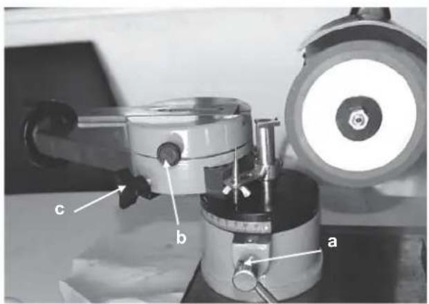
Fig. 1
Basically it is possible to sharpen saw discs of diameter
80 mm - 700 mm.
Fix the disc on the feed slide. The feed slide has three centring holes. According to the centring hole, it is possible to mount various diameters of saw discs.
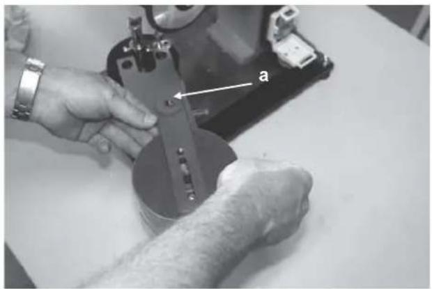
Fig. 2
First, select a centring hole and loosen up the clamping screw (Fig. 1b), now, the feed slide may turn by 360°. With small diameters of the saw disc it is recommended to use a centring hole (Fig. 2a), on medium diameters, one of two additional holes. Using a hand wheel, it is possible, upper slide may be adjusted. First loosen clamping screw out (Fig. 1c). The diameter of the disc to be worked may be set up after it is loosened up.

natural_image
Close-up of hands adjusting a metallic cylindrical object with a labeled point 'a' and light reflections (no text or symbols on the object itself)Fig. 3
When you find an appropriate distance between the centring hole and the grinding wheel, fix the upper slide with clamping screw (Fig. 1c), Now, the disc may be placed in the middle of centring hole. Now, put a suitable adapter in the saw disc Put clamping disc (Fig. 3a) above the adapter and fix it with a screw.
TIP: Tighten the clamping screw so that the saw disc may bet turned without taking too much power.

natural_image
Close-up of a mechanical component with a metallic surface and a white arrow pointing to a feature (no visible text or symbols)Fig. 4
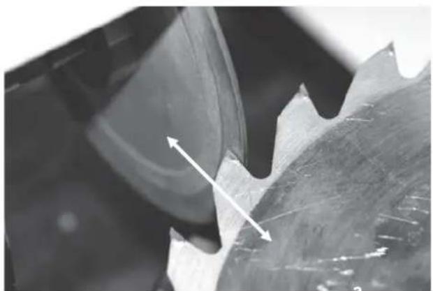
First, determine the cutting angle of sharpening the teeth inner surfaces. The surfaces should be parallel to the flat area of the grinding. Se arrow in Fig.4 and Fig. 5)
natural_image
Close-up of a mechanical component with a serrated edge and directional arrows indicating motion (no text or symbols)Fig. 5
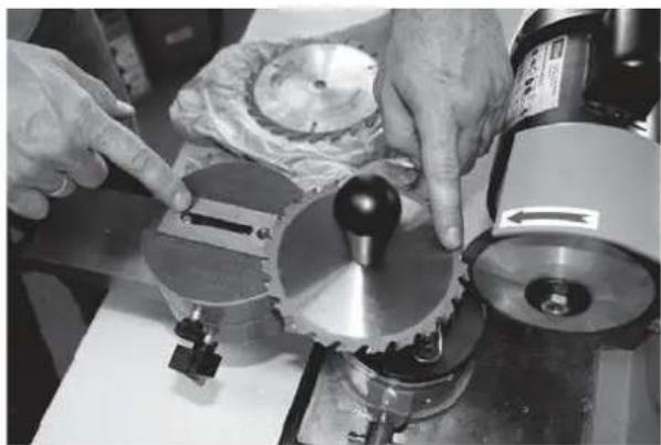
Sharpening is done by sliding the slide forward and backward. Mind the slide set up to provide for the hard metal surface to be sharpened The oblong hole in the slide works as a stop. (see Fig. 6)

natural_image
Close-up of hands operating a mechanical assembly with gears and a cutting tool (no visible text or symbols)Fig. 6
Here, it is clear that the feed slide is set in parallel to the grinding wheel and the slide goes to the stop, the grinding wheel works the hard metal surface only. Also, the set up to work smaller grinding wheel.
Caution: Be very careful to move the saw disc on the slide in order to prevent any damage of the diamond disc!
| Fig. 7 | A stop needle should be mounted on to avoid grinding the saw disc. It should be calibrated and locked in place with a socket wrench. |
| Fig. 8 | Teeth are marked with the selector pen which makes the removal well recognisable and controllableIf the grinding wheel angle is set up in the way providing for even grinding of the inner surfaces of the teeth, the disc may be worked tooth by tooth.Caution:Always take the saw disc beck completely and avoid any jerky movements that could damage the grinding wheel. |
| Fig. 9 | The inclined front side of the grinding wheel is used to sharpen roof-like cutting edges. The angles should be determined and set up in an appropriated way. In this case too, use the stop pike to observe the final even diameter of the saw disc.Caution: To make turn of the tool slide in the position correct for grinding roof-like cutting edges, it is necessary to turn the stop needle to the motor side. (Fig. 9A) |
| Fig. 9A | To do that, socket screw should be loosened up (Fig. 9A-A) and the stop needle turned on the side of motor. |

natural_image
Close-up of a mechanical gear and cutting tool in operation, with an inset showing a close-up of the tool (no visible text or symbols)Fig. 10
With alternating teething, the grinding wheel should be adapted to inclination to the alternating tooth (every other tooth is sharpened)

natural_image
Close-up of a hand operating a precision cutting machine tool with a metallic component (no visible text or symbols)Fig. 11
Set up the pre-adjusted angle in reverse direction. It is possible to sharpen the remaining teeth now.
Tip: Use a selector pen.

natural_image
Close-up of a precision optical instrument with dual lenses and a central rotating component (no visible text or symbols)Fig. 12
If grinding small saw discs, it helps to remove supporting screws. That should be found out individually according to the saw disc and cutting edge geometry.
6.1 Operator Safety Instructions

Unplug the unit before any maintenance/adjustment and repair. Unplug after finishing the work as well.
- Do not use the unit before you have read the operating manual carefully.
- Observe all the safety instructions indicated in the manual.
- Be responsible to the others.
6.2 Step by Step Instructions
- Turn the slide with a clamping hole to the required position according to the saw disc diameter.
- Choose a suitable clamping adaptor and fix the disc in place.
- Set up the slide so that it is not possible to sharpen the disc mistakenly when there is a hit on the horizontal hole.
- Mark the teeth internal surfaces with a black pen and put the grinding wheel in the standstill on the area to be ground.
- Switch the sharpening machine and scrape the surface marked in black off to enable additional calibration.
- Grind very carefully, according to the saw disc diameter, one tooth after another.
- When grinding of all inner teeth areas are finished, grind evenly the teeth slopes on the inclined area of the disc using a stop to provide for eccentric run of the disc.
- Clean the unit carefully.
7 Troubles-Causes- Troubleshooting
Caution: Always check the overheating protection first!
| Trouble | Cause | Troubleshooting |
| Burning disc (blunt) | 1. The sharpening surface excessively lubricated.2. Worn diamond layer. | 1. Clean the unit with the sharpening tool.2. Replace the disc |
7.1.1 Inspections and Maintenance

Unplug the unit before any maintenance/adjustment and cleaning. Unplug upon finishing the work as keep the machine clean and free of any dust. Oil the slide well to prevent jerking.
7.2 Grinding Wheel Replacement

Fig. 13
To replace the wheel, lock it on the spindle at either side with a forked wrench. The lock nut may be loosened or tightened in the direction of the motor turning (clockwise thread)
7.3 Inspections and Maintenance Safety Instructions
Only a unit maintained and cared for on a regular basis may be a serviceable aid. Insufficient maintenance and care may result in emergencies and unforeseen accidents.
7.4 Inspections and Maintenance Schedule
| Time Interval | Description | Other Details if Required |
| After every use | Wipe the unit with clean dry cloth or blow off with low -pressure air. |
8 Spare Parts

Claims and orders of spar parts shall be executed/satisfied in a fast manner free of any administrative hinders if a respective servicing form is used. Download the form at
http://www.guede.com/support
The form may also be requested from
Phone: +49 (0) 79 04 / 700-0
Fax: +49 (0) 79 04 / 700-250
E-Mail: info@guede.com
1 Appareil
natural_image
Row of eight metallic washers or washers arranged in a row, no text or symbols visible1.2 Garantie
natural_image
Close-up of hands adjusting a metallic cylindrical object with a labeled point 'a' and light reflections (no text or symbols on the object itself)Fig. 3
natural_image
Close-up of a mechanical component with a metallic surface and a white arrow pointing to a feature (no visible text or symbols)Fig. 4
natural_image
Close-up of a mechanical component with a serrated edge and directional arrows indicating motion (no text or symbols)Fig. 5
natural_image
Close-up of hands operating a mechanical assembly with gears and a cutting tool (no visible text or symbols)Fig. 6
natural_image
Close-up of mechanical components with a magnified inset showing a tool interacting with a component (no visible text or symbols)natural_image
Close-up of hands using a tool to work on a mechanical component, no visible text or symbolsFig. 8
natural_image
Close-up of a mechanical component with a tool inserted, showing a small inset image of a hand holding a small object (no visible text or symbols)Fig. 9
natural_image
Close-up of a mechanical assembly with labeled parts A and B, showing no readable text or symbols.Fig. 9A
natural_image
Close-up of a mechanical gear or cutting tool with an inset showing a close-up of a tool (no visible text or symbols)Fig. 10
natural_image
Close-up of a hand operating a precision cutting machine tool with a metallic component (no visible text or symbols)Fig. 11
natural_image
Close-up of a precision optical instrument with dual lenses and a central rotating component (no visible text or symbols)Fig. 12
natural_image
Close-up of hands adjusting a metallic cylindrical object with a labeled point 'a' and light reflections (no text or symbols on the object itself)Obr. 3
natural_image
Close-up of a mechanical component with a metallic surface and a black arrow pointing to a feature, no visible text or symbols.Obr. 4
natural_image
Close-up of a mechanical component with a serrated edge and directional arrows indicating motion (no text or symbols)Obr. 5
natural_image
Close-up of hands operating a mechanical assembly with gears and a cutting tool (no visible text or symbols)Obr. 6
natural_image
Close-up of a CNC machine tool in operation, showing a cutting tool and workpiece (no visible text or symbols)Obr. 7
natural_image
Close-up of hands using a tool to work on a mechanical component, no visible text or symbolsObr. 8
natural_image
Close-up of a mechanical component with a tool inserted, showing a curved surface and a small inset view (no text or symbols visible)Obr. 9
natural_image
Close-up of a robotic arm operating a precision tool, labeled A and B (no visible text or symbols beyond labels)Obr. 9A
natural_image
Close-up of a mechanical gear and cutting tool in operation, with an inset showing a close-up of the tool (no visible text or symbols)Obr. 10
natural_image
Close-up of a hand operating a precision cutting machine tool with a metallic component (no visible text or symbols)Obr. 11
natural_image
Close-up of a precision optical instrument with dual lenses and a central rotating component (no visible text or symbols)Obr. 12
natural_image
Row of seven metallic washers or washers arranged in a row, no text or symbols visible1.2 Záruka
natural_image
Close-up of hands pressing a circular hole on a metallic cylindrical surface, with an arrow pointing to the hole (no text or symbols visible)Obr. 3
natural_image
Close-up of a mechanical component with a white arrow indicating direction, no visible text or symbolsObr. 4
natural_image
Close-up of a mechanical component with two white arrows pointing to specific areas (no text or symbols visible)Obr. 5
natural_image
Close-up of hands operating a mechanical gear assembly with a cutting tool (no visible text or symbols)Obr. 6
natural_image
Close-up of a mechanical tool in operation, showing a cutting machine and workpiece with no visible text or symbols.Obr. 7
natural_image
Close-up of a hand using a tool to work on a mechanical component, no visible text or symbolsObr. 8
natural_image
Close-up of a mechanical component with a tool inserted, showing a curved surface and a small inset image (no text or symbols visible)Obr. 9
natural_image
Close-up of a mechanical device with labeled parts A and B, showing motion or assembly (no readable text or symbols beyond labels)Obr. 9A
natural_image
Close-up of a mechanical gear and cutting tool in operation, with no visible text or symbolsObr. 10
natural_image
Close-up of a hand operating a mechanical gear assembly with a conical tool (no visible text or symbols)Obr. 11
Teraz sa nastaví prednastavený uhol v opačnom smere. Teraz je možné naostrit' zvyšné zuby.
natural_image
Close-up of a precision optical instrument with dual lenses and a central dial (no visible text or symbols)Obr. 12
natural_image
Row of eight metallic washers or washers arranged in a row, no text or symbols visible1.2 Garantie
natural_image
Close-up of hands operating a large metallic cylindrical device with a circular hole and a pointed tip, no visible text or symbols.Afb. 3
natural_image
Close-up of a mechanical component with a white arrow indicating direction, no visible text or symbolsAfb. 4
natural_image
Close-up of a mechanical component with visible cracks and a white arrow indicating direction (no text or symbols)Afb. 5
natural_image
Close-up of hands operating a mechanical gear assembly with a cutting machine (no visible text or symbols)Afb. 6
natural_image
Close-up of a mechanical tool in operation, showing a cutting machine and a workpiece (no visible text or symbols)Afb. 7
natural_image
Close-up of a hand using a tool to work on a mechanical component, no visible text or symbolsAfb. 8
natural_image
Close-up of a mechanical component with a tool inserted, showing a curved surface and a small inset image (no text or symbols visible)Afb. 9
natural_image
Close-up of a mechanical tool with labeled components A and B, showing motion direction (no readable text or symbols beyond labels)Afb. 9A
natural_image
Close-up of a mechanical gear and cutting tool in operation, with no visible text or symbolsAfb. 10
natural_image
Close-up of a hand operating a mechanical gear assembly (no visible text or symbols)Afb. 11
natural_image
Close-up of a precision optical instrument with dual lenses and a central dial (no visible text or symbols)Afb. 12
natural_image
Row of seven metallic washers or washers arranged in a row, no text or symbols visible1.2 Garanzia
natural_image
Close-up of hands operating a large metallic cylindrical device with a circular hole and a pointed tip, no visible text or symbols.Fig. 3
natural_image
Close-up of a mechanical component with a white arrow indicating direction, no visible text or symbolsFig. 4
natural_image
Close-up of a mechanical component with visible cracks and texture, no text or symbols presentFig. 5
natural_image
Close-up of hands operating a mechanical gear assembly with a cutting machine (no visible text or symbols)Fig. 6
natural_image
Close-up of mechanical components with no visible text or symbolsFig. 7
natural_image
Close-up of a hand using a tool to work on a mechanical component, no visible text or symbolsFig. 8
natural_image
Close-up of a mechanical component with a tool inserted, showing a wavy surface and a small inset view (no text or symbols visible)Fig. 9
natural_image
Close-up of a mechanical gear and cutting tool in operation, with no visible text or symbolsFig. 10
natural_image
Close-up of a hand operating a mechanical gear assembly (no visible text or symbols)Fig. 11
natural_image
Close-up of a precision optical instrument with dual lenses and a central dial (no visible text or symbols)Fig. 12
6.2 Manuale step by step
natural_image
Row of seven metallic washers or washers arranged in a row, no text or symbols visible1.2 Jótállás
natural_image
Close-up of hands adjusting a metallic cylindrical object with a labeled point 'a' and light reflections (no text or symbols on the object itself)3.ábra
natural_image
Close-up of a mechanical component with a metallic surface and a black arrow pointing to a feature, no visible text or symbols.- ábra
natural_image
Close-up of a mechanical component with a serrated edge and directional arrows indicating motion (no text or symbols)5.ábra
natural_image
Close-up of hands operating a mechanical assembly with gears and a cutting tool (no visible text or symbols)6.ábra
natural_image
Close-up of a CNC machine tool in operation, showing a cutting tool and workpiece (no visible text or symbols)7.ábra
natural_image
Close-up of hands using a tool to work on a mechanical component, no visible text or symbols8.ábra
natural_image
Close-up of a sewing machine needle stitching fabric, with an inset showing the needle tip (no text or symbols visible)9.ábra
natural_image
Close-up of a mechanical gear or cutting tool with a close-up inset showing a tool (no visible text or symbols)10.ábra
natural_image
Close-up of a hand operating a precision cutting machine tool with a metallic component (no visible text or symbols)11.ábra
natural_image
Close-up of a precision optical instrument with dual lenses and a central rotating component (no visible text or symbols)12.ábra
natural_image
Row of seven metallic washers or washers arranged in a row, no text or symbols visible1.2 Garancija
natural_image
Close-up of hands adjusting a metallic cylindrical object with a labeled point 'a' and light reflections (no text or symbols on the object itself)Slika 3
natural_image
Close-up of a mechanical component with a metallic surface and a black arrow pointing to a feature, no visible text or symbols.Slika 4
natural_image
Close-up of a mechanical component with a serrated edge and directional arrows indicating motion (no text or symbols)Slika 5
natural_image
Close-up of hands operating a mechanical assembly with gears and a cutting tool (no visible text or symbols)Slika 6
natural_image
Close-up of a mechanical gear and cutting tool in operation, with an inset showing a close-up of the tool (no visible text or symbols)Slika 10
natural_image
Close-up of a hand operating a precision cutting machine tool with a metallic component (no visible text or symbols)Slika 11
natural_image
Close-up of a precision optical instrument with dual lenses and a central rotating component (no visible text or symbols)Slika 12
Kadar brusimo manjše žagine liste, je primerno da odvijemo prislonske vijake. To individualno prilagodimo velikosti žaginega lista in geometriji rezil.
- Ručni točkić
- Pomične saonice
- Pritisni kolut
- Stezni vijak
- Igla - graničnik
- Stezna poluga koluta za brušenje
- Prekidač za slučaj nužde
- Brusni kolut
- Potporni vijak
- Stezna poluga potpornog stola
- Stezni vijak gornjih saonica
- Stezni vijak pomičnih saonica
- Adapteri

natural_image
Row of seven metallic washers arranged in a row, no text or symbols visible1.2 Jamstvo
Garantni rok je 12 mjeseci prilikom industrijske uporabe, a 24 mjeseca za potrošača i počinje na dan prodaje uređaja.
Jamstvo se odnosi samo na nedostatke, koji su nastali zbog kvarnog materijala ili putem proizvodnje. Neophodno je, da se prilikom reklamacije dopremi i račun, koji mora biti potpisan od strane prodavača i obilježen datumom te pečatom prodavaonice.
U okvir jamstva ne spadaju kvarovi, koji bi nastali putem nepravilne uporabe kao npr.: preopterećenje stroja, rukovanje silom odnosno zbog štetnog dodira sa stranim predmetima.
natural_image
Close-up of hands adjusting a metallic cylindrical object with a labeled point 'a' and light reflections (no text or symbols on the object itself)Slika br. 3
Nakon što ste utvrdili odgovarajuću udaljenost između otvora za centriranje i kotača za oštrenje, fiksirajte saonice pomoću steznog vijka (slika br. 1c). Sada možete položiti brusni kotač na sredinu otvora za centriranje. Sada stavite u otvor ploče za sječenje odgovarajući adapter. Iznad adaptera sada stavite tlačni kotač (slika br. 3a) i učvrstite ga steznim vijkom.
SAVIJET: Malo pritegnite stezni vijak, i to tek tako da se rezna ploča može lako okretati.

natural_image
Close-up of a mechanical component with a metallic surface and a black arrow pointing to a feature, no visible text or symbols.Slika br. 4
natural_image
Close-up of a mechanical component with a serrated edge and directional arrows indicating motion (no text or symbols)Slika br. 5
Oštrenje se vrši pomicanje saonica unaprijed i unazad, s time da je potrebno osigurati da pomične saonice budu namještene tako da će pritom dolaziti samo do oštrenja površine od tvrdog metala; otvor u saonicama služi samo kao graničnik. (Slika br. 6)
natural_image
Close-up of hands operating a mechanical assembly with gears and a cutting tool (no visible text or symbols)Slika br. 6
Ovdje se jasno vidi da su pomične saonice namještene paralelno s brusnim kotačem za oštrenje i saonice se pomiču skroz do kraja, i kotač za oštrenje brusi samo površinu od tvrdog metala. Pored toga se jasno vidi da je uređaj podešen za manju ploču za sječenje.
natural_image
Close-up of a CNC machine tool in operation, showing a cutting tool and workpiece (no visible text or symbols)Slika br. 7
Kako ne bi dolazilo do brušenja ploče za sječenje, neophodno je montirati iglu koja služi kao graničnik. Igla se kalibrira i zateže imbus ključem na potpornom vijku.

natural_image
Close-up of hands using a tool to work on a mechanical component, no visible text or symbolsSlika br. 8
natural_image
Close-up of a sewing machine needle stitching fabric, with an inset showing the needle detail (no text or symbols visible)Slika br. 9
natural_image
Close-up of a robotic arm cutting metal components, labeled A and B (no text or symbols on the mechanical part)Slika br. 9A
Prije toga je potrebno popustiti imbus vijak (slika br. 9A-A) i igla-graničnik mora biti okrenuta na stranu motora!

natural_image
Close-up of a mechanical gear and cutting tool in operation, with an inset showing a close-up of the tool (no visible text or symbols)Slika br. 10
Kod naizmjeničnih zubaca kotač za oštrtenje mora biti prilagođen kutu zubaca na jednoj strani (oštri se svaki drugi zubac).

natural_image
Close-up of a hand operating a precision cutting machine tool with a metallic component (no visible text or symbols)Slika br. 11
Sada podesite kut u obrnutom smjeru za oštenje preostalih zubaca. Nakon toga naoštrite preostale zupce.
Savjet: Pri radu koristite pero za odabir zubaca.

natural_image
Close-up of a precision optical instrument with dual lenses and a central rotating component (no visible text or symbols)Slika br. 12
- Ručni točkić
- Saonice za dodavanje
- Kotur za pritiskanje
- Pritezni zavrtanj
- Granična igla
- Pritezna poluga kotura za brušenje
- Prekidač u slučaju nužde
- Kotur za brušenje
- Potporni zavrtanj
- Pritezna poluga potpornog stola
- Pritezni zavrtanj gornjih saonica
- Pritezni zavrtanj saonica za dodavanje
- Adapteri

natural_image
Row of eight metallic washers arranged in a row, no text or symbols visible1.2 Garancija
Garancija važi 12 mjeseci u slučaju industrijske upotraebe, a 24 mjeseca za potrošača; počinje važiti na dan prodaje uređaja.
Garancija se odnosi samo na nedostatke, koji su nastali zbog kvarnog materijala ili prilikom proizvodnje. Neophodno je, da se u slučaju reklamacije dopremi i račun ili faktura, koja mora biti potpisana od strane prodavca i obilježena datumom i pečatom prodavaonice.
U okvir garancije ne spadaju kvarovi, koji bi nastali putem nepravilne uporabe kao npr.: preopterećenje uređaja, rukovanje silom odnosno zbog štetnog kontakta sa drugim predmetima.
2 Opšte upute za bezbjednost na radu
Prije prvog stavljanja mašine u rad neophodno je pročitati sve informacije i podatke koji su navedena u Uputama za upotrebu. U slučaju bilo kakvih sumnji ili poteškoća u vezi instalacije i rukovanja sa mašinom obratite se proizvođaču (Servisu).
ZBOG OBEZBJEĐIVANJA VISOKOG STEPENA SIGURNOSTI I BEZBJEDNOSTI PRILIKOM RADA SA MAŠINOM PRIDRŽAVAJTE SE, SLIJEDEĆIH UPUTSTAVA ZA RAD:
UPOZORENJE!
natural_image
Close-up of hands adjusting a metallic cylindrical object with a labeled point 'a' and light reflections (no text or symbols on the object itself)Obr. 3
natural_image
Close-up of a mechanical component with a metallic surface and a black arrow pointing to a feature, no visible text or symbols.Obr. 4
natural_image
Close-up of a mechanical component with a serrated edge and directional arrows indicating motion (no text or symbols)Obr. 5
Oštrenje se vrši pomicanjem saonica unaprijed i unazad, s tim da je potrebno osigurati da ponične saonice budu namještene tako da će pritom dolaziti samo do oštrenja površine od tvrdog metala; otvor u saonicama služi samo kao graničnik. (Slika br. 6)

natural_image
Close-up of hands operating a mechanical assembly with gears and a cutting tool (no visible text or symbols)Obr. 6
Ovdje se jasno vidi da su pomične saonice namještene paralelno sa brusnim točkom za oštrenje i saonice se pomiču skroz do kraja, i točak za oštrenje brusi samo površinu od tvrdog metala. Pored toga se jasno vidi da je uređaj podešen za manju reznu ploču.
natural_image
Close-up of a CNC machine tool in operation, showing a cutting tool and workpiece (no visible text or symbols)Obr. 7
Kako ne bi dolazilo do brušenja reznog točka, neophodno je montirati iglu koja služi kao graničnik. Igla se kalibrira i zateže imbus ključem na potpornom zavrtnju.

natural_image
Close-up of hands using a tool to work on a mechanical component, no visible text or symbolsObr. 8
natural_image
Close-up of a mechanical component with a tool inserted, showing a wavy surface and a small inset image (no text or symbols visible)Obr. 9
natural_image
Close-up of a mechanical gear and cutting tool in operation, with an inset showing a close-up of the tool (no visible text or symbols)Obr. 10
Kod naizmjeničnih zubaca točak za oštrenje mora biti prilagođen uglu zubaca na jednoj strani (oštri se svaki drugi zubac).

natural_image
Close-up of a hand operating a precision cutting machine tool with a metallic component (no visible text or symbols)Obr. 11
natural_image
Close-up of a precision optical instrument with dual lenses and a central rotating component (no visible text or symbols)Obr. 12
natural_image
Row of seven metallic washers with holes, labeled '13' at bottom left (no other text or symbols)1.2 Garantie
natural_image
Close-up of hands operating a large metallic cylindrical device with a circular hole and a pointed tip, no visible text or symbols.Fig. 3
natural_image
Close-up of a mechanical component with a white arrow indicating direction, no visible text or symbolsFig. 4
natural_image
Close-up of a mechanical component with visible cracks and texture, no text or symbols presentFig. 5
natural_image
Close-up of hands operating a mechanical gear assembly on a workbench (no visible text or symbols)Fig. 6
natural_image
Close-up of mechanical components with no visible text or symbolsFig. 7
natural_image
Close-up of a hand using a tool to work on a mechanical component, no visible text or symbolsFig. 8
natural_image
Close-up of a mechanical component with a metallic tool inserted, showing internal structure and texture (no visible text or symbols)Fig. 9
natural_image
Close-up of a mechanical robotic arm with labeled parts A and B, showing motion direction (no text or symbols beyond labels)Fig. 9A
natural_image
Close-up of a mechanical gear and cutting tool in operation, with no visible text or symbolsFig. 10
natural_image
Close-up of a hand operating a mechanical gear assembly with a conical tool (no visible text or symbols)Fig. 11
natural_image
Close-up of a precision optical instrument with dual lenses and a central dial (no visible text or symbols)Fig. 12
natural_image
Row of seven metallic washers arranged in a row, no text or symbols visible1.2 Гаранция
natural_image
Close-up of hands adjusting a metallic cylindrical object with a labeled point 'a' and light reflections (no text or symbols on the object itself)Kapt. 3
natural_image
Close-up of a mechanical component with a metallic surface and an arrow pointing to a specific feature (no visible text or symbols)Карт. 4
natural_image
Close-up of a mechanical component with a serrated edge and directional arrows indicating motion (no text or symbols)Kapt. 5
natural_image
Close-up of hands operating a mechanical assembly with gears and a cutting tool (no visible text or symbols)Карт. 6
natural_image
Close-up of a precision machining setup with tool and workpiece (no visible text or symbols)Kapt. 7
natural_image
Close-up of hands using a tool to work on a mechanical component, no visible text or symbolsКарт. 8
natural_image
Close-up of a mechanical component with a metallic tool inserted, showing internal structure and texture (no visible text or symbols)Kapt. 9
natural_image
Close-up of a mechanical tool interacting with a gear-like component, no visible text or symbolsКарт. 10
natural_image
Close-up of a hand operating a CNC machine tool with a cutting tool inserted into a workpiece (no visible text or symbols)Карт. 11
natural_image
Close-up of a precision optical instrument with dual lenses and a central rotating component (no visible text or symbols)Карт. 12
EC-DECLARATION OF CONFORMITY
We, hereby declare the conception and construction of the below mentioned appliances correspond - at the type of construction being launched - to appropriate basic safety and hygienic requirements of EC Directives. In case of any change to the appliance not discussed with us the Declaration expires.
DECLARATION CE DE CONFORMITE
PROHLASENI O SHODE EU


- Gewährleistung
- Scope of Delivery
- Warranty
- General Safety Instructions
- FOLLOW THE INSTRUCTIONS BELOW CAREFULLY IN ORDER TO SECURE A HIGH DEGREE OF SAFETY:
- Caution!
- Emergency Action
- Signs on Unit
- Meaning of Symbols
- Packaging
- Technical Data:
- Assigned Use
- Residual Hazards and Protective Action
- Mechanical Residual Hazards
- Electrical Residual Hazards
- Noise Hazards
- Materials and Other Substances Hazards
- Human Factors Neglect
- Other Hazards
- Disposal
- Operator Requirements
- Qualification
- Minimum Age
- Training
- Technical Data
- Transportation and Storage
- Assembly and Initial Operation
- Initial Operation Safety Instructions
- Procedure
- Operation
- Operator Safety Instructions
- Step by Step Instructions
- Troubles-Causes- Troubleshooting
- Inspections and Maintenance
- Grinding Wheel Replacement
- Inspections and Maintenance Safety Instructions
- Inspections and Maintenance Schedule
- Spare Parts
- Appareil
- Garantie
- Záruka
- Garanzia
- Manuale step by step
- Jótállás
- Garancija
- Jamstvo
- Opšte upute za bezbjednost na radu
- ZBOG OBEZBJEĐIVANJA VISOKOG STEPENA SIGURNOSTI I BEZBJEDNOSTI PRILIKOM RADA SA MAŠINOM PRIDRŽAVAJTE SE, SLIJEDEĆIH UPUTSTAVA ZA RAD:
- UPOZORENJE!
- Гаранция
- EC-DECLARATION OF CONFORMITY
- DECLARATION CE DE CONFORMITE
- PROHLASENI O SHODE EU
Brand : GUDE
Model : GSS 700 P
Category : Grinder