
Evolution 1150 Tower - Inverter EATON - Free user manual and instructions
Find the device manual for free Evolution 1150 Tower EATON in PDF.


| Product type | Line-interactive UPS |
| Brand | Eaton |
| Model | Evolution 1150 Tower |
| Apparent power (VA) | 1150 VA |
| Active power (W) | 650 W |
| Topology | Line-interactive with Automatic Voltage Regulation (AVR) |
| Nominal input voltage | 230 V AC |
| Nominal output voltage | 230 V AC |
| Number of output sockets | 8 sockets (including 4 with surge protection and battery backup) |
| Battery runtime at full load | Approximately 5 minutes |
| Dimensions (W × D × H) | 230 × 370 × 88 mm |
| Net weight | 12.5 kg |
| Power supply | Internal sealed lead-acid battery, maintenance-free |
| Main functions | Surge protection, automatic voltage regulation, noise filter, cold start, USB management |
| Maintenance and cleaning | Regularly dust the ventilation grilles with a dry cloth |
| Safety | Protection against short circuits, overloads, and deep discharges |
| Spare parts and repairability | User-replaceable battery, accessible protection fuse |
| General information | Manufacturer's warranty 2 years, Eaton Intelligent Power Manager management software included |
Frequently Asked Questions - Evolution 1150 Tower EATON
User questions about Evolution 1150 Tower EATON
0 question about this device. Answer the ones you know or ask your own.
Ask a new question about this device
Download the instructions for your Inverter in PDF format for free! Find your manual Evolution 1150 Tower - EATON and take your electronic device back in hand. On this page are published all the documents necessary for the use of your device. Evolution 1150 Tower by EATON.
USER MANUAL Evolution 1150 Tower EATON
Pulsar Series
Evolution
650 / 650 Rack 1U
850 / 850 Rack 1U
1150 / 1150 Rack 1U
1550 / 1550 Rack 1U
Installation and user manual
English
Français
Deutsch
Italiano
Español
Nederlands
Русский
Evolution
650/650 Rack 1U
850/850 Rack 1U
1150/1150 Rack 1U
1550/1550 Rack 1U

Installation and user manual
Pulsar Series
Thank you for selecting an EATON product to protect your electrical equipment.
The Evolution range has been designed with the utmost care.
We recommend that you take the time to read this manual to take full advantage of the many features of your UPS (Uninterruptible Power System).
Before installing Evolution, please read the booklet presenting the safety instructions. Then follow the indications in this manual.
To discover the entire range of EATON products and the options available for the Evolution range, we invite you to visit our web site at www.eaton.com or contact your EATON representative.
Environmental protection
EATON has implemented an environmental-protection policy.
Products are developed according to an eco-design approach.
Substances
This product does not contain CFCs, HCFCs or asbestos.
Packing
To improve waste treatment and facilitate recycling, separate the various packing components.
- The cardboard we use comprises over 50% of recycled cardboard.
- Sacks and bags are made of polyethylene.
- Packing materials are recyclable and bear the appropriate identification symbol

| Material Abbreviation Number | in the symbol | |
| Polyethylene terephthalate PET 01 | ||
| High-density polyethylene HDPE 02 | ||
| Polyvinyl chloride PVC 03 | ||
| Low-density polyethylene LDPE 04 | ||
| Polypropylene | PP | 05 |
| Polystyrene | PS | 06 |
Follow all local regulations for the disposal of packing materials.
End of life
EATON will process products at the end of their service life in compliance with local regulations.
EATON works with companies in charge of collecting and eliminating our products at the end of their service life.
Product
The product is made up of recyclable materials.
Dismantling and destruction must take place in compliance with all local regulations concerning waste.
At the end of its service life, the product must be transported to a processing centre for electrical and electronic waste.
Battery
The product contains lead-acid batteries that must be processed according to applicable local regulations concerning batteries.
The battery may be removed to comply with regulations and in view of correct disposal.
Introduction
Pictograms

Important instructions that must always be followed.
Information, advice, help.
Visual indication.
Action.
Audio signal.
In the illustrations on the following pages, the symbols below are used:

LED off
LED on
LED flashing
1. Presentation
1.1 Standard positions 6
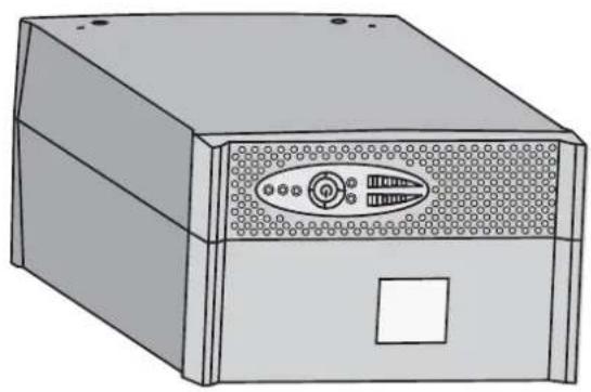
Tower models 6
Rack models....6
1.2 Rear panels 7
Evolution 650/850/1150/1550 7
Evolution 650/850/1150/1550 Rack 7
1.3 Control panel 7
2. Installation
2.1 Unpacking and contents check....8
2.2 Installation of tower model....9
2.3 Installation of rack model 9
2.4 Installation 650 rack model....10
2.5 Communication ports....11
Connection of RS232 or USB communication port (optional) 11
Installation of the communication cards (optional) 11
Characteristics of the contact communication port (optional) 11
2.6 Equipment connections 12
3. Operation
3.1 Start-up and normal operation....13
3.2 Operation on battery power 13
3.3 Return of AC input power 13
3.4 UPS shutdown 14
3.5 UPS remote-control functions....14
4. Measurements and personalisation 15
5. Maintenance
5.1 Troubleshooting....16
5.2 Replacing the battery module in the tower model....16
Safety recommendations....16
Battery-module removal....16
Mounting the new battery module 17
5.3 Replacing the battery module in the rack model....17
Safety recommendations....17
Battery-module removal....17
Mounting the new battery module....18
5.4 Training centre....18
6. Appendices
6.1 Technical specifications....19
6.2 Glossary 20
1. Presentation
1.1 Standard positions
Tower models


| Dimensions (H x W x D)in mm | |
| Evolution 650 234 x 1 | 47 x 418 |
| Evolution 850 234 x 1 | 47 x 418 |
| Evolution 1150 234 x | 147 x 418 |
| Evolution 1550 234 x | 147 x 492 |
| Weights in kg | |
| Evolution 650 8.4 | |
| Evolution 850 10.8 | |
| Evolution 1150 12.5 | |
| Evolution 1550 16.5 | |
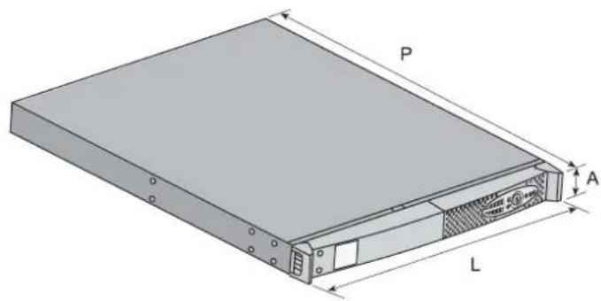
Rack models

| Dimensions (H x W x D)in mm | |
| Evolution 650 Rack 43 | .5 x 438 x 366 |
| Evolution 850 Rack 43 | .5 x 438 x 512 |
| Evolution 1150 Rack 43 | 3.5 x 438 x 512 |
| Evolution 1550 Rack 43 | 3.5 x 438 x 556 |
| Weights in kg | |
| Evolution 650 Rack 10.1 | |
| Evolution 850 Rack 16.1 | |
| Evolution 1150 Rack 16.6 | |
| Evolution 1550 Rack 20 |
1. Presentation
1.2 Rear panels
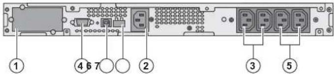
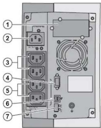
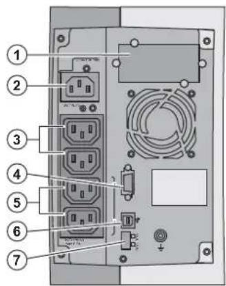
Evolution 650/850/1150/1550

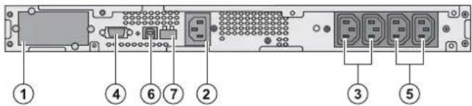
(1) Slot for optional communication card
(2) Socket for connection to AC-power source
(3) 2 outlets for connection of equipment
(4) RS232 communication port
(5) 2 programmable outlets (1 and 2) for connection of equipment
(6) USB communication port
(7) Connector for remote ON/OFF and RPO (Remote Power Off) control
Evolution 650/850/1150/1550 Rack
Evolution 650/850/1150 Rack

Evolution 1550 Rack

1.3 Control panel


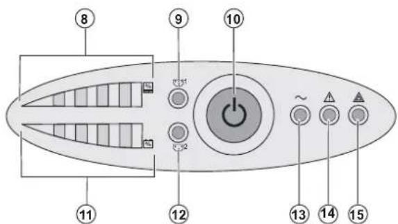
(8) Bargraph indicating the percent load
(9) Programmable outlet 1 is supplied
(10) ON/OFF button for UPS and outlets
(11) Bargraph indicating battery-charge level
(12) Programmable outlet 2 is supplied
(13) Load protected LED
(14) Downgraded operation LED
(15) Load not protected LED
Bargraphs (8) and (11)


2. Installation
2.1 Unpacking and contents check

(16) Evolution UPS, tower or rack model
(17) 2 connection cables for the protected equipment
(18) Documentation
(19) Solution-Pac CD-ROM
(20) RS232 communication cable
(21) USB communication cable
(22) Mounting kit for 19-inch bays (rack model only, except 650 Rack)
(23) System to secure power plugs (rack model only)

Packing materials must be disposed of in compliance with all local regulations concerning waste.
Recycling symbols are printed on the packing materials to facilitate sorting.
2. Installation
2.2 Installation of tower model

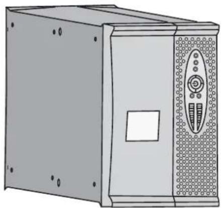

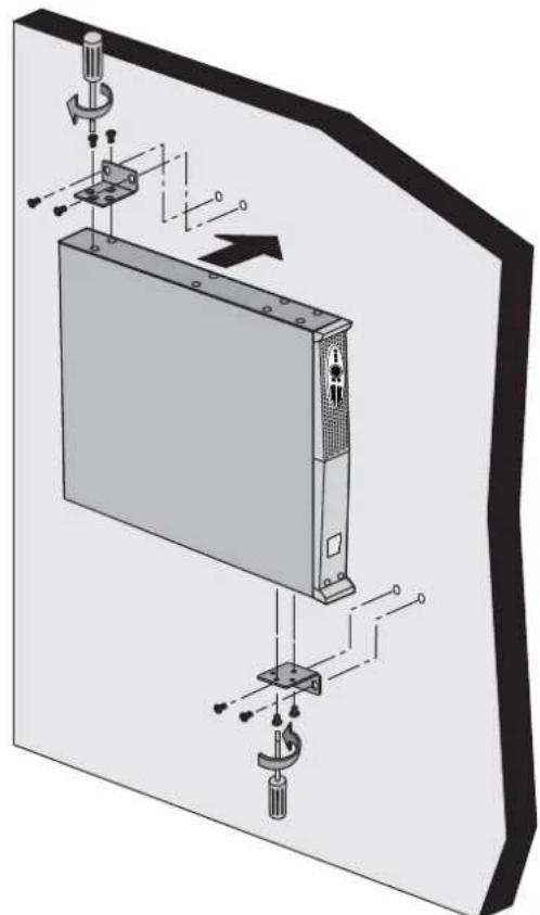
2.3 Installation of rack model

Follow steps 1 to 4 for module mounting on the rails.


The rails and necessary hardware are supplied by EATON.
2. Installation
2.4 Installation of the 650 rack model

Follow steps 1 to 3 for rack mounting.


The necessary hardware is supplied by EATON.
2. Installation
2.5 Communication ports
Connection of RS232 or USB communication port (optional)

The RS232 and USB communication ports cannot operate simultaneously.

![graph TD A["CPU"] --> B["Monitor"] B --> C["Server"] C --> D["Warning Symbol"] style A fill:#f9f,stroke:#333 style B fill:#ccf,stroke:#333 style C fill:#cfc,stroke:#333 style D fill:#fcc,stroke:#333](/content/2026/06/1264178/images/a69eb0b049459f0ff87ca6b96ce0c1cd5f812b1cff354b1c23ece7e53c49db56.jpg)
1 - Connect the RS232 (20) or USB (21) communication cable to the serial or USB port on the computer equipment.
2 - Connect the other end of the communication cable (20) or (21) to the USB (6) or RS232 (4) communication port on the UPS.
The UPS can now communicate with EATON power management software.

Installation of the communication cards (optional)


Limited-access slot for the communication card
It is not necessary to shutdown the UPS before installing a communication card.
1 - Remove the slot cover (1) secured by screws.
2 - Insert the communication card in the slot.
3 - Secure the card cover with the two screws.
Characteristics of the contact communication port (optional)

- Pins 1, 2, 3, 5, 6: not used
- Pin 4: common (user)
- Pin 7: low battery
• Pin 8: UPS ON, equipment supplied - Pin 9: operation on battery power
n.o.: normally open contact
When a signal is activated, the contact is closed between the common (pin 4) and the pin for the corresponding signal.
Contact characteristics (optocoupler)
• Voltage: 48 V DC max
- Current: 25 mA max
Power: 1.2 W
2. Installation
2.6 Equipment connections


Check that the indications on the name plate located on the back of the UPS correspond to the AC-power source and the true electrical consumption of the total load.

1 - Disconnect the supply cable (1) (not supplied) of the equipment. 2 - Connect the cable to socket (2), then to the AC-power source. 3 - Connect the loads to the UPS using the cables (17). It is preferable to connect the priority loads to the two outlets marked (3) and the non-priority loads to the two programmable outlets marked (5) (1 and 2).
To program shutdown of outlets (5) during operation on battery power and thus optimise the available backup time, the EATON communication software is required.
(1) Cable characteristics: 250 V - 10 A (CSA 1mm2 , type HO5).


Fit the connection securing system. (rack model only).

4 - Fit the connection securing system (23) that prevents the plugs from being pulled out accidentally.

Note. The UPS charges the battery as soon as it is connected to the AC-power source, even if button (10) is not pressed.
Once the UPS is connected to the AC-power source, eight hours of charging are required before the battery can supply the rated backup time.
3. Operation
3.1 Start-up and normal operation


The connected devices are protected by the UPS.
Press button (10) for approximately 1 second.
- The buzzer beeps once and all the LEDs go ON simultaneously.
- If AC input power is available, button (10) and LED (13) are ON. The load is supplied by the AC-power source. Conditions permitting, the UPS runs a battery test, indicated by LEDs (11) and the buzzer.
- If AC input power is not available, button (10) and LEDs (13) and (14) are ON. The load is supplied by the UPS on battery power.

If LED (15) is ON, a fault has occurred (see the "Troubleshooting" section).
3.2 Operation on battery power
Transfer to battery power


The connected devices are supplied by the battery.
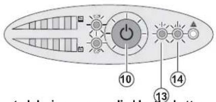
- The connected devices continue to be supplied by the UPS when AC input power is no longer available. The necessary energy is provided by the battery.
- Button (10) and LEDs (13) and (14) are ON.
• The audio alarm beeps every ten seconds.

Low-battery warning


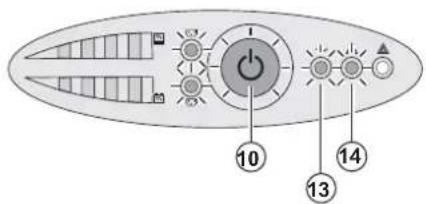
- Button (10) and LEDs (13) and (14) are ON.
• The audio alarm beeps every three seconds.
The remaining battery power is low.
Shut down all applications on the connected equipment because automatic UPS shutdown is imminent.
End of battery backup time

- All the LEDs go OFF.
- The audio alarms stops.

The UPS is completely shut down.
3.3 Return of AC input power
Following an outage, the UPS restarts automatically when AC input power returns (unless the restart function has been disabled via UPS personalisation) and the load is again supplied.
3. Operation
3.4 UPS shutdown

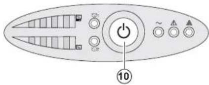
Press button (10) for approximately 2 seconds.
The devices connected to the UPS are no longer supplied.
3.5 UPS remote-control functions

Evolution offers a choice between two remote control functions.
- RPO (Remote Power Off) allows a remote contact to be used to disconnect all the equipment connected to the UPS. Restarting the UPS requires manual intervention.
- ROO (Remote ON/OFF) allows remote action of button (10) to shut down the UPS.
These functions are obtained by opening of the contact connected between the appropriate pins of connector (7) on the rear panel of the UPS (see figures below).
Remote control connection and test

1 - Check that the UPS is OFF and disconnected from the AC input source.
2 - Remove connector (7) after unscrewing the screws.
3 - Connect a normally closed volt-free contact (60 V DC / 30 V AC max., 20 mA max., 0.75 mm 4 cable cross-section) between the two pins of connector (7) (see diagram).

Contact open: UPS shutdown

Contact closed: UPS start-up (UPS connected to AC power and AC power is available)
Note. The local ON/OFF control using button (10) overrides the remote-control function.

Contact open: UPS shutdown, LED (14) goes ON.
To return to normal operation, deactivate the remote external contact and restart the UPS by pressing button (10).
4 - Plug connector (7) into the back of the UPS.
5 - Connect and restart the UPS following the previously described procedures.
6 - Activate the external remote shutdown contact to test the function.

Warning. This connector must only be connected to SELV (Safety Extra-Low Voltage) circuits.
4. Access to measurements and personalisation data

- Insert the Solution-Pac CD-ROM in the drive.
- On the first navigation screen, select "Point to Point solution" and follow the instructions on how to install the Personal Solution-Pac software.
- Then select "Settings", "Advanced settings" and "UPS settings".
Note that the Linux/Unix/MacOS versions of Personal Solution-Pac software do not offer this possibility. It is possible to modify the settings listed below (detailed comments are available in the Personal Solution-Pac software).
Main-output personalisation
| Function Factory setting Other available settings | ||
| Output voltage on battery power 230 Volts AC 200/208/220/240 Volts AC | ||
| Overload alarm threshold 105% 30/50/70% |
Voltage-threshold personalisation
| Function Factory setting Other available settings | ||
| High threshold for transfer to battery 294 Volts AC 271 to 294 Volts AC | ||
| Low threshold for transfer to battery 160 Volts AC 160 to 180 Volts AC | ||
| Fader activation threshold 265 Volts AC 244 to 265 Volts AC | ||
| Booster activation threshold 184 Volts AC 184 to 207 Volts AC | ||
| Maximum input-voltage range Disabled | Enabled | (1) |
(1) Low threshold for transfer to battery: 150 V.
UPS-sensitivity personalisation
| Function Factory setting Other available settings | ||
| UPS-sensitivity level | Normal | High or low |
UPS ON/OFF personalisation
| Function Factory setting Other available settings | ||
| Automatic start | Enabled | Disabled |
| Cold start | Enabled | Disabled |
| Forced shutdown | Enabled | Disabled |
| Energy-savings mode | Disabled | Enabled |
| UPS ON/OFF controlled by software | Enabled | Disabled |
| Battery level before restart | 0% | 0 to 100% |
Battery personalisation
| Function Factory setting Other available settings | ||
| Battery-test intervals | Weekly No test / daily test / monthly test | |
| Low-battery warning | 20% | 0 to 100% |
| Battery protection against deep discharge | Enabled | Disabled |
| Audio alarm | Enabled | Disabled |
5. Maintenance
5.1 Troubleshooting
| Indication Diagnostic Correction | |||
| 1 When the UPS is started using button (10), all the LEDs go ON once and the buzzer beeps once, then LED (14) remains ON. | The remote power off (RPO) contact has been activated to shut down the UPS and now prevents restart. | Set the contact back to its normal position and press button (10) to restart. | |
| 2 | Button (10) and LEDs (13) and (14) are ON and all the LEDs on bargraph (8) flash. | The percent load is greater than the set overload level or UPS capacity. | Check the power drawn by the connected devices and disconnect any non-priority devices. Check the overload level setting. |
| 3 | Button (10) and LED (15) are ON and all the LEDs on bargraph (8) are flashing. | A critical overload has occurred on the UPS output. If AC input power fails, the load will not be supplied in battery mode. | Check the power drawn by the connected devices and disconnect any non-priority devices. |
| 4 | LED (15) is ON and all the LEDs on bargraph (11) are flashing. | A battery fault has been detected during the automatic test. | Replace the battery module (see section 5.2, Battery-module replacement). |
| 5 | LED (15) alone is ON and the buzzer sounds continuously. | A UPS internal fault has occurred and the load is not supplied. | Call the after-sales support department. |
5.2 Replacing the battery module in the tower model
Safety recommendations
The battery can cause electrocution and high short-circuit currents. The following safety precautions are required before servicing the battery components:
- Remove watches, rings, bracelets and all other metal objects from the hands and arms,
- Use tools with an insulated handle.
Battery-module removal


The UPS must be turned as shown in the figure opposite.
A - Remove the two screws on the left-hand side.


B - Lift and pull away the panel with the logo.


C - Pull on the two connectors to disconnect the battery (never pull on the wires).
D - Pull the plastic tab to remove the battery.
Mounting the new battery module
Carry out the above instructions in reverse order.

To ensure safety and high performance, use only batteries supplied by EATON.
Take care to firmly press together the two parts of the connector during remounting.
5.3 Replacing the battery module in the rack model
Safety recommendations
The battery can cause electrocution and high short-circuit currents. The following safety precautions are required before servicing the battery components:
, Remove watches, rings, bracelets and all other metal objects from the hands and arms,
, Use tools with an insulated handle.
- Remove watches, rings, bracelets and all other metal objects from the hands and arms, - Use tools with an insulated handle.
Battery-module removal

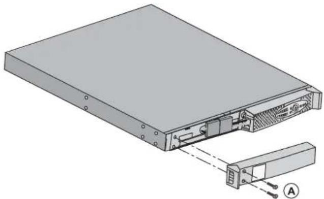
A - Remove the two screws on the left-hand side of the front panel.


B - Disconnect the battery block by separating the two connectors (never pull on the wires).


C - Remove the part.
5. Maintenance


D - Pull the plastic tab to remove the battery block and replace it.
Mounting the new battery module
Carry out the above instructions in reverse order.

• To ensure safety and high performance, use only batteries supplied by EATON.
Take care to firmly press together the two parts of the connector during remounting.
5.4 Training centre

To fully master operation of your EATON product and carry out level 1 servicing, see our complete range of technical training courses, available in both French and English.
For further information, please visit our website: www.eaton.com
6. Appendices
6.1 Technical specifications
![graph LR A["FilterChargerInverter"] --> B["Transformer 'AVR'"] B --> C["Battery"] C --> D["Output"]](/content/2026/06/1264178/images/35f1fa3c1a287cb3482fa0d97f75021b9f8ed6cf7c0da6bbe65b288531796744.jpg)
| Evolution | 650 / 650 Rack | 850 / 850 Rack | 1150 / 1150 Rack | 1550 / 1550 Rack |
| Output power 650 VA / | 420 W | 850 VA /600 W | 1150 VA /770 W | 1550 VA /1100 W |
| AC input powerRated input voltageInput-voltage range50 Hz input-frequency range60 Hz input-frequency range | Single phase 220~240 V160 V to 294 V (1)47 Hz to 70 Hz (2)56.5 Hz to 70 Hz (2) | |||
| Output on battery powerVoltageFrequency | 230 V (+6% / -10%) (3)50/60 Hz ±0.1 Hz | |||
| Battery (sealed lead acid, maintenance free)Tower modelRack model | 1 x 12 V - 9 Ah2 x 6 V - 9 Ah | 2 x 12 V - 7.2 Ah4 x 6 V - 7.2 Ah | 2 x 12 V - 9 Ah4 x 6 V - 9 Ah | 3 x 12 V - 9 Ah6 x 6 V - 9 Ah |
| EnvironmentOperating temperature rangeStorage temperature rangeHumidityNoise level | 0 to 35°C 0 to 40°C | |||
| -25°C to 40°C20 to 90% (without condensation)< 40 dbA | ||||
(1) The high and low thresholds can be adjusted using Personal Solution-Pac software.
(2) Up to 40 Hz in extended frequency mode (programmable using Personal Solution-Pac software).
(3) Adjustable to 200 V (10% derating of output power) / 208 V / 220 V / 230 V / 240 V.
When the appliance is used in EU area, use an external circuit breaker in front of line with rating 16A, 250V which is IEC/EN 60898-1 standard compliant;
When the appliance is used in America area, use an external circuit breaker in front of line with rating 20A, 250V.
This product is designed for IT power distribution system.
6. Appendices
6.2 Glossary
| Backup time | Time during which the load can be supplied by the UPS operating on battery power. |
| Battery test Internal UPS test to check battery status. | |
| Booster mode | Automatic UPS mode that steps up the AC voltage if it is too low, to a level above the personalised set-point, without discharging the battery. |
| Cold start | The devices connected to the UPS can be started even if AC input power is not available. The UPS operates on battery power alone. |
| Deep discharge | Battery discharge beyond the permissible limit, resulting in irreversible damage to the battery. |
| Fader mode | Automatic UPS mode that steps down the AC voltage if it is too high, to a level below the personalised set-point, without discharging the battery. |
| Load Devices or equipment connected to the UPS output. | |
| Low-battery warning | This is a battery-voltage level indicating that battery power is low and that the user must take action in light of the imminent break in the supply of power to the load. |
| Normal AC input The AC-power line supplying the UPS under normal conditions. | |
| Percent load | Ratio of the power effectively drawn by the load to the maximum output of the UPS. |
| Personalisation | It is possible to modify certain UPS parameters set in the factory. Certain UPS functions can also be modified by the Personal Solution-Pac software to better suit user needs. |
| Programmable outlets | Controllable outlets for automatic load shedding, remote shutdown and sequential restart (personalised using Personal Solution-Pac software. |
| UPS Uninterruptible Power System. | |
| UPS ON/OFF controlled by software | This function enables or disables initiation of UPS ON/OFF control sequences by computer power-management software. |
Evolution
650/650 Rack 1U
850/850 Rack 1U
1150/1150 Rack 1U
1550/1550 Rack 1U
1.1 Positions standards 6
Modèles tour....6
Modèles rack 6
1.2 Faces arrières....7
Evolution 650/850/1150/1550 7
Evolution 650/850/1150/1550 Rack 7
1.1 Positions standards
Modèles tour

| Tableau des dimensions (H x L x P)en mm | |
| Evolution 650 234 x 1 | 47 x 418 |
| Evolution 850 234 x 1 | 47 x 418 |
| Evolution 1150 234 x | 147 x 418 |
| Evolution 1550 234 x | 147 x 492 |
| Tableau des masses en kg | |
| Evolution 650 8,4 | |
| Evolution 850 10,8 | |
| Evolution 1150 12,5 | |
| Evolution 1550 16,5 | |
Modèles rack

| Tableau des dimensions (H x L x P) en mm | |
| Evolution 650 Rack 43 | ,5 x 438 x 366 |
| Evolution 850 Rack 43 | ,5 x 438 x 512 |
| Evolution 1150 Rack 43 | ,5 x 438 x 512 |
| Evolution 1550 Rack 43 | ,5 x 438 x 556 |
| Tableau des masses en kg | |
| Evolution 650 Rack 10,1 | |
| Evolution 850 Rack 16,1 | |
| Evolution 1150 Rack 16,6 | |
| Evolution 1550 Rack 20 |
1. Présentation
1.2 Faces arrières
Evolution 650/850/1150/1550

Evolution 1550 Rack


ASI Alimentation Sans Interruption.
Installations- und
Bedienungsanleitung
Pulsar Series
| Abmessungen (H x B x T)in mm | |
| Evolution 650 234 x 1 | 47 x 418 |
| Evolution 850 234 x 1 | 47 x 418 |
| Evolution 1150 234 x | 47 x 418 |
| Evolution 1550 234 x | 47 x 492 |
| Gewicht in kg | |
| Evolution 650 8,4 | |
| Evolution 850 10,8 | |
| Evolution 1150 12,5 | |
| Evolution 1550 16,5 | |
Rack-Modell

| Abmessungen (H x B x T)in mm | |
| Evolution 650 Rack 43 | ,5 x 438 x 366 |
| Evolution 850 Rack 43 | ,5 x 438 x 512 |
| Evolution 1150 Rack 43 | ,5 x 438 x 512 |
| Evolution 1550 Rack 43 | ,5 x 438 x 556 |
| Gewicht in kg | |
| Evolution 650 Rack 10,1 | |
| Evolution 850 Rack 16,1 | |
| Evolution 1150 Rack 16,6 | |
| Evolution 1550 Rack 20 |
Evolution 1550 Rack


C - Blech abnehmen.
For further information, please visit our website: www.eaton.com
| Tabella delle dimensioni (A x L x P)in mm | |
| Evolution 650 237 x 1 | 47 x 418 |
| Evolution 850 237 x 1 | 47 x 418 |
| Evolution 1150 237 x | 147 x 418 |
| Evolution 1550 237 x | 147 x 492 |
| Tabella dei pesi in kg | |
| Evolution 650 8,4 | |
| Evolution 850 10,8 | |
| Evolution 1150 12,5 | |
| Evolution 1550 16,5 | |
Modelli rack
| Tabella delle dimensioni (A x L x P) in mm | |
| Evolution 650 Rack 43 | ,5 x 438 x 366 |
| Evolution 850 Rack 43 | ,5 x 438 x 512 |
| Evolution 1150 Rack 43 | ,5 x 438 x 512 |
| Evolution 1550 Rack 43 | ,5 x 438 x 556 |
| Tabella dei pesi in kg | |
| Evolution 650 Rack 10,1 | |
| Evolution 850 Rack 16,1 | |
| Evolution 1150 Rack 16,6 | |
| Evolution 1550 Rack 20 |
1. Presentazione
1.2 Vista posteriore
Evolution 650/850/1150/1550
Evolution 1550 Rack



For further information, please visit our website: www.eaton.com
| Cuadro de dimensiones (A x L x P) en mm | |
| Evolution 650 234 x 1 | 47 x 418 |
| Evolution 850 234 x 1 | 47 x 418 |
| Evolution 1150 234 x | 147 x 418 |
| Evolution 1550 234 x | 147 x 492 |
2 Evolution 1150 12,5
| Cuadro de pesos en kg. | |
| Evolution 650 8,4 | |
| Evolution 850 10,8 | |
| Evolution 1550 16,5 | |
Modelos rack

| Cuadro de dimensiones (A x L x P) en mm | |
| Evolution 650 Rack 43 | ,5 x 438 x 366 |
| Evolution 850 Rack 43 | ,5 x 438 x 512 |
| Evolution 1150 Rack 43 | ,5 x 438 x 512 |
| Evolution 1550 Rack 43 | ,5 x 438 x 556 |
| Cuadro de pesos en kg. | |
| Evolution 650 Rack 10,1 | |
| Evolution 850 Rack 16,1 | |
| Evolution 1150 Rack 16,6 | |
| Evolution 1550 Rack 20 |
1. Presentación
1.2 Caras traseras
Evolution 650/850/1150/1550

Evolution 1550 Rack


For further information, please visit our website: www.eaton.com
Installatie- en
6.2 Definities.... 20
1. Beschrijving
| Overzicht afmetingen (H x B x D)in mm | |
| Evolution 650 234 x 1 | 47 x 418 |
| Evolution 850 234 x 1 | 47 x 418 |
| Evolution 1150 234 x | 147 x 418 |
| Evolution 1550 234 x | 147 x 492 |
| Overzicht gewichten in kg | |
| Evolution 650 8,4 | |
| Evolution 850 10,8 | |
| Evolution 1150 12,5 | |
| Evolution 1550 16,5 | |
Rackmodellen

| Overzicht afmetingen (H x B x D)in mm | |
| Evolution 650 Rack | 43,5 x 438 x 366 |
| Evolution 850 Rack | 43,5 x 438 x 512 |
| Evolution 1150 Rack | 43,5 x 438 x 512 |
| Evolution 1550 Rack | 43,5 x 438 x 556 |
| Overzicht gewichten in kg | |
| Evolution 650 Rack 10,1 | |
| Evolution 850 Rack 16,1 | |
| Evolution 1150 Rack 16,6 | |
| Evolution 1550 Rack 20 | |
1. Beschrijving
1.2 Achterkant
Evolution 650/850/1150/1550
Evolution 1550 Rack

1.3 Bedieningspaneel



For further information, please visit our website: www.eaton.com
UPS Uninterruptible Power Supply (ononderbroken stroomvoorziening.
Pulsar Series
Evolution
650/650 Rack 1U
850/850 Rack 1U
1150/1150 Rack 1U
1550/1550 Rack 1U
Руководство
по установке
и эксплуатации
Evolution 1550 Rack


MGE Office Protection Systems

For further information, please visit our website: www.eaton.com
6. Приложения

- EVOLUTION
- INSTALLATION AND USER MANUAL
- PULSAR SERIES
- ENVIRONMENTAL PROTECTION
- SUBSTANCES
- PACKING
- END OF LIFE
- PRODUCT
- BATTERY
- INTRODUCTION
- PICTOGRAMS
- PRESENTATION
- INSTALLATION
- OPERATION
- MEASUREMENTS AND PERSONALISATION 15
- MAINTENANCE
- APPENDICES
- 1.1 STANDARD POSITIONS
- 1.2 REAR PANELS
- EVOLUTION 650/850/1150/1550 RACK
- 1.3 CONTROL PANEL
- BARGRAPHS (8) AND (11)
- 2.1 UNPACKING AND CONTENTS CHECK
- 2.2 INSTALLATION OF TOWER MODEL
- 2.3 INSTALLATION OF RACK MODEL
- 2.4 INSTALLATION OF THE 650 RACK MODEL
- 2.5 COMMUNICATION PORTS
- CHARACTERISTICS OF THE CONTACT COMMUNICATION PORT (OPTIONAL)
- CONTACT CHARACTERISTICS (OPTOCOUPLER)
- 2.6 EQUIPMENT CONNECTIONS
- 3.1 START-UP AND NORMAL OPERATION
- 3.2 OPERATION ON BATTERY POWER
- END OF BATTERY BACKUP TIME
- 3.3 RETURN OF AC INPUT POWER
- 3.4 UPS SHUTDOWN
- 3.5 UPS REMOTE-CONTROL FUNCTIONS
- REMOTE CONTROL CONNECTION AND TEST
- ACCESS TO MEASUREMENTS AND PERSONALISATION DATA
- 5.1 TROUBLESHOOTING
- 5.2 REPLACING THE BATTERY MODULE IN THE TOWER MODEL
- SAFETY RECOMMENDATIONS
- BATTERY-MODULE REMOVAL
- MOUNTING THE NEW BATTERY MODULE
- 5.3 REPLACING THE BATTERY MODULE IN THE RACK MODEL
- 5.4 TRAINING CENTRE
- 6.1 TECHNICAL SPECIFICATIONS
- 6.2 GLOSSARY
- 1.1 POSITIONS STANDARDS
- PRÉSENTATION
- 1.2 FACES ARRIÈRES
- PRESENTAZIONE
- 1.2 VISTA POSTERIORE
- PRESENTACIÓN
- 1.2 CARAS TRASERAS
- BESCHRIJVING
- 1.2 ACHTERKANT
- 1.3 BEDIENINGSPANEEL
- ПРИЛОЖЕНИЯ
Brand : EATON
Model : Evolution 1150 Tower
Category : Inverter