
YP3040 - Photo Accessories AXIS - Free user manual and instructions
Find the device manual for free YP3040 AXIS in PDF.


| Product Type | Photo accessory |
| Brand | Axis |
| Model | YP3040 |
| Dimensions (L x W x H) | 15 x 10 x 5 cm |
| Weight | 200 g |
| Main material | ABS plastic with rubber finish |
| Compatibility | DSLR, mirrorless and compact cameras with standard hot shoe |
| Main functions | Remote trigger, zoom control, auto focus |
| Power supply | 2 AAA batteries (not included) |
| Wireless range | Up to 30 meters |
| Battery life | Approximately 100 hours of continuous use |
| Operating frequency | 2.4 GHz |
| Operating temperature | -10°C to 50°C |
| Care and cleaning | Wipe with a soft, dry cloth. Do not use solvents. |
| Safety | Do not expose to water or excessive humidity. Keep out of reach of children. |
| Spare parts and repairability | Replacement batteries and USB-C cable available. Repair by Axis authorized center. |
| General information | 2-year warranty. Made in China. |
Frequently Asked Questions - YP3040 AXIS
User questions about YP3040 AXIS
0 question about this device. Answer the ones you know or ask your own.
Ask a new question about this device
Download the instructions for your Photo Accessories in PDF format for free! Find your manual YP3040 - AXIS and take your electronic device back in hand. On this page are published all the documents necessary for the use of your device. YP3040 by AXIS.
USER MANUAL YP3040 AXIS
YP3040 Pan-Tilt Motor
About this Document
This document includes instructions for installing the YP3040 Pan-Tilt Motor.
Legal Considerations
Video and audio surveillance can be prohibited by laws that vary from country to country. Check the laws in your local region before using this product for surveillance purposes.
Electromagnetic Compatibility (EMC)
If use of this equipment causes harmful interference to radio or television reception, which can be determined by turning the equipment off an on, the user is encouraged to try to correct the interference by one of more of the following measures: Re-orient or relocate the receiving antenna. Increase the separation between the equipment and receiver. Connect the equipment to an outlet on a different circuit to the receiver. Consult your dealer or an experienced radio/TV technician for help. Shielded (STP) network cables must be used with this unit to ensure compliance with EMC standards.
USA - This equipment has been tested and found to comply with the limits for a Class A digital device, pursuant to Part 15 of the FCC rules. These limits are designed to provide reasonable protection against harmful interference when the equipment is operated in a commercial environment. This equipment generates, uses and can radiate radion frequency energy and, if not installed and used in accordance with the instruction manual, may cause harmful interference to radion communications. Operation of this equipment in a residential area is likely to cause interference, in which case the user will be required to correct the interference at his own expense.
Canada - This Class A digital apparatus complies with Canadian ICES-003.
Europe - This digital equipment fulfills the requirements for radiated emission according to limit A of EN55022/1998, and the requirements for immunity according to EN55024/1998 residential, commercial, and industry.
Warning! This is a Class A product. In a domestic environment this product may cause radio interference, in which case the user may be required to take adequate measures.
Japan - This is a class A product based on the standard of the Voluntary Control Council for Interference by Information Technology Equipment VCCI. If this equipment is used in a domestic environment, radio disturbance may arise.
Australia - This electronic device meets the requirements of the Radio communications (Electromagnetic Compatibility) Standard AS/NZS CISPR22:2002. This is a class A product In a domestic environment this product may cause radio interference in which case the user may be required to take adequate measures.
Korea - This equipment has obtained EMC registration for business use (Class A), and is intended for use in commercial environments.
Equipment Modifications
This equipment must be installed and used in strict accordance with the instructions given in the user documentation. This equipment contains no user-serviceable components. Unauthorized equipment changes or modifications will invalidate all applicable regulatory certifications and approvals.
Liability
Every care has been taken in the preparation of this document. Please inform your local Axis office of any inaccuracies or omissions. Axis Communications AB cannot be held responsible for any technical or typographical errors and reserves the right to make changes to the product and documentation without prior notice. Axis Communications AB makes no warranty of any kind with regard to the material contained within this document, including, but not limited to, the implied warranties of merchantability and fitness for a particular purpose. Axis Communications AB shall not be liable nor responsible for incidental or consequential damages in connection with the furnishing, performance or use of this material.
RoHS
This product complies with both the European RoHS directive, 2002/95/EC, and the Chinese RoHS regulations, ACPEIP.

WEEE Directive
The European Union has enacted a Directive 2002/96/EC on Waste Electrical and Electronic Equipment (WEEE Directive). This directive is applicable in the European Union member states.

The WEEE marking on this product (see right) or its documentation indicates that the product must not be disposed of together with household waste. To prevent possible harm to human health and/or the environment, the product must be disposed of in an approved and environmentally safe recycling process. For further information on how to dispose of this product correctly, contact the product supplier, or the local authority responsible for waste disposal in your area.
Business users should contact the product supplier for information on how to dispose of this product correctly. This product should not be mixed with other commercial waste.
Support
Should you require any technical assistance, please contact your Axis reseller. If your questions cannot be answered immediately, your reseller will forward your queries through the appropriate channels to ensure a rapid response. If you are connected to the Internet, you can:
- download user documentation
• find answers to resolved problems in the FAQ database. Search by product, category, or phrases - report problems to Axis support by logging in to your private support area.
YP3040 Installation Guide
This installation guide provides instructions for installing the YP3040 Pan-Tilt Motor.
Installation steps
- Check the package contents against the list below.
- Hardware overview. See page 4.
- Install the hardware.
• Install the wall bracket, see page 5.
• Install the Pan-Tilt motor, see page 5.
• Install the camera in the housing, see page 5.
• Install the housing on the Pan-Tilt motor, see page 5.
- Connect the cables, see page 6.
- Setup, see page 7.
Important!
This product must be used in compliance with local laws and regulations.
1 Package contents
| Item Models/variants/notes | |
| Pan-tilt motor YP3040 | |
| Mounting kit 2 screws M5 | x10 for mounting the camera housing on the splint4 bolts for mounting the pan-tilt motor on the recommended wall bracket1 allen key |
| Printed materials YP3040 | Installation Guide (this document)Drill template (with YP3040 Wall Bracket)Axis Warranty Document |
| Optional accessories | See www.axis.com for information on product documentation, installation tools, cameras, power accessories, and housings |
Recommended accessories
| Item Models/variants/notes | |
| Wall bracket YP3040 Wall | Bracket for YP3040 Pan-Tilt Motor |
| Mains adaptor | AXIS PS24 Mains Adaptor, power supply input 100–230 V AC, suitable for indoor and outdoor use |
| Housing AXIS T92A20 Housing to be mounted on YP3040 Pan-Tilt Motor | |
| Network cameras AXIS P13-E seriesAXIS Q1755-EAXIS Q1910-E | |

Hardware overview

Note:
For functions behind the side panel, refer to About the DIP switch settings, on page 9
3 Install the hardware
Install the wall bracket
- Prepare the wall for installation of the wall bracket (recommended accessory), use the supplied drill template to position the holes. Make sure to use drill bits, screws, and plugs that are appropriate for the material.
IMPORTANT! - To avoid collision, make sure there is enough clearance around the pan-tilt motor and camera/camera housing (minimum clearance to the ceiling is 60 cm or 24 in. from the top edge of the wall bracket).
-
Pull the cables through the wall bracket, see illustration on page 7.
-
Attach the wall bracket to the wall with the round platform facing upwards.
IMPORTANT! - Make sure to leave enough slack to allow for the cables to twist and bend along with the unit.
Install the Pan-Tilt Motor
-
Place the pan-tilt motor on the wall bracket, see illustration on page 4 for alignment and direction of tilt
-
Secure the pan-tilt motor by tightening the supplied bolts.
Install the camera in the housing
Install the camera in the housing according to the instructions in the Installation Guide provided with the housing. Make sure to allow for the PTZ control cable to pass through the housing to the camera, see Connect the cables, on page 6. For more information, see the Installation Guides provided with the housing and the camera.
Install the housing on the Pan-Tilt Motor
-
Detach the splint by removing the mounting screws on the brace, using the supplied allen key. See illustration on page 4.
-
Use the supplied 2 countersunk screws to mount the housing on the splint.
-
Attach the splint with the housing to the brace.
Splint dimensions
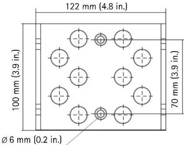
Mounting holes for housing/camera, see Recommended accessories, on page 3
Connect the cables
- Connect the power supply to the pan-tilt motor according to the Installation Guide supplied with the mains adaptor. The recommended mains adaptor is AXIS PS24 Mains Adaptor. For more information on this product, see the Axis web site at www.axis.com
| Wire color Connect to | ||
| Power supply cable 24 V AC | Red | 24 V AC on power supply |
| Red 24 V AC on power supply | ||
| Yellow/green GND |
- Connect the PTZ control cable to the camera's RS-485 port. Different camera models have different terminal connectors, be sure to follow the correct description for the installed camera. The correct connector is supplied with the Axis network camera. For more information on Axis network cameras, see the Axis web site at www.axis.com
| Wire color Connect to | ||
| PTZ control cable (RS-485) Red A+ on camera | ||
| Blue B- on camera |
- Connect the camera to the network, see the Installation Guide provided with the camera.
Note:
The RJ-45 connector for the network cable will not pass through the cable gland on the underside of the housing. The cable must be cut, threaded through the cable gland and then re-crimped.

4 Setup
When you install a compatible Axis network camera on the YP3040 Pan-Tilt Motor, the controls will be available from the Live View page in the camera's web pages after enabling the PTZ functionality in Setup tools. Follow these instructions to enable PTZ functionality in the camera:
- Go to Setup > System Options > Ports & Devices > COM Port in the camera's web pages, and set Usage to Pan Tilt.
- Refer to the User's Manual supplied with your product for instructions on how to configure the PTZ settings.
Technical specifications
| Unit Function Description | |||
| YP3040 | Input voltage 24 V AC 50/60 Hz | ||
| Power consumption 30 VA | |||
| Movement range Pan 0° to 355° | |||
| Tilt 10° to -80° | |||
| Movement speed Pan 7.5°/s | |||
| Tilt 6°/s | |||
| Protocol (default) Pelco-D | |||
| Bit rate (default) 2400 bps | |||
| Address (default) 1 | |||
| Operating temperature -20°C to 65°C (-4°F to 149°F) | |||
| Load | Torque (brace axis, see page 4) | 1.5 N m (1.1 ft. lb) | |
| Load type Top load | |||
| Maximum load | 10 kg (22 lb) | ||
| Weight | 4.2 kg (9 lb) | ||
| Protection class | IP66 (indoor and outdoor use) | ||
| Construction | Aluminum alloy | ||
Troubleshooting
| Problem | Probable cause | Remedy |
| YP3040 does not move | No power applied | Check that power supply is connected |
| Faulty connection in power supply | Check that power supply cable is intact and connected correctly | |
| YP3040 moves when power is applied, but is otherwise unresponsive to commands | Faulty RS-485 cable connection to network camera | Check that RS-485 cable is intact and connected correctly |
| PTZ functionality not enabled in network camera | Check that PTZ functionality is enabled in Setup tools, see Setup, on page 7 |
About the DIP switch settings
The transmission between the motor and the camera will not work if the camera uses a different protocol and bit rate than the motor. For cameras with a different protocol than the Pelco-D and bit rate of 2400 bps, the dip switches must be changed, see Change the DIP switch settings, on page 10.
Note:
The default factory settings of the YP3040 Pan-Tilt Motor are the Pelco-D protocol and a bit rate of 2400 bps. This means that the DIP switch settings do not need to be changed when using the motor with an Axis network camera with the Pelco-D protocol.
The YP3040 Pan-Tilt Motor has two sets of 8 digital DIP switches.

The 8 switches on the left-hand side are used to select functions such as protocol, bit rate, and terminal resistance. The 8 switches on the right-hand side are used to select multiple unique addresses when connecting several units in a series through a multi-channel video server. There are 255 different switch combinations.
Note:
In a typical installation only the one default address is required.
Change the DIP switch settings
- Loosen the 4 side panel mounting screws and remove the side panel.
- Set the 8 switches to select functions. Switches 1, 2, 3, and 4 are used to select the PTZ control protocol. Switch 7 is always OFF. Switch 8 is used to connect a terminal resistance of 120 , switch to ON when required.
| S e l e c t | f | u | n | c | t | i | o | n | |
| Protocol Pelco-D (default) ON ON OFF OFF | |||||||||
| Pelco-P OFF ON OFF OFF | |||||||||
| AD/AB OFF OFF ON OFF | |||||||||
| Bit rate 2400 bps (default) OFF OFF | |||||||||
| 4800 bps ON OFF | |||||||||
| 9600 bps OFF ON | |||||||||
| 19200 bps ON ON | |||||||||
| Terminal resistance OFF (default) | OFF | ||||||||
| 120 Ω | ON | ||||||||
| OFF | |||||||||
- Set the 8 switches to select address.
- Replace the side panel and tighten the screws.
Safeguards & warnings
- Please read through this Installation Guide carefully prior to installing your product. Keep the Installation Guide for further reference.
- Turn off the power before cleaning the motor. Do not use chemicals, caustic agents, or aerosol cleaners. Use a damp cloth for cleaning.
- Only use accessories and replacement parts provided or recommended by Axis.
- Use 24 V AC power supply only, AXIS PS24 Mains Adaptor is recommended.
- Protect the power supply cable from any damage; pay special attention to plug fittings, extensions and outputs.
• Install a surge protector to protect the motor from power surges. - Avoid using excessively long installation wires in order to prevent fire or electrical shocks.
- Do not remove the covers or repair the product by yourself, contact Axis or your Axis reseller for service matters.
IMPORTANT! - Keep the motor clear of unidentified objects or corrosive liquids since that may cause the motor to short circuit.
IMPORTANT! - Do not install the motor on unstable brackets, unstable or vibrating surfaces or walls, since this may cause injury to people or damage the motor.
IMPORTANT! - Do not touch the motor during operation.
IMPORTANT! - Do not install or operate the motor on dangerous sites that store inflammable or explosive objects.
Installation du support mural
$$ O N = E I N, A U S = O F F $$
$$ O N = E I N, A U S = O F F $$
© Axis Communications AB, 2009-2010
Ver.1.2
Printed: July 2010
Part No. 40110
- About this Document
- Legal Considerations
- Electromagnetic Compatibility (EMC)
- Equipment Modifications
- Liability
- RoHS
- WEEE Directive
- Support
- YP3040 Installation Guide
- Installation steps
- Important!
- Hardware overview
- Install the hardware
- Install the wall bracket
- Install the Pan-Tilt Motor
- Install the camera in the housing
- Install the housing on the Pan-Tilt Motor
- Splint dimensions
- Connect the cables
- Note:
- Setup
- About the DIP switch settings
- Change the DIP switch settings
- Safeguards & warnings
- Installation du support mural
Brand : AXIS
Model : YP3040
Category : Photo Accessories