
24 V - Shutter and blind motors SOMFY - Free user manual and instructions
Find the device manual for free 24 V SOMFY in PDF.


| Product type | 24 V control unit for motorization of shutters and blinds |
| Brand | SOMFY |
| Model | 24 V |
| Power supply | 230 V AC, 50/60 Hz, protection 10 A |
| Motor output | 24 V DC, max current according to motor |
| Dimensions (approximate) | 300 x 200 x 100 mm |
| Weight (approximate) | 2 kg |
| Main functions | Pulse control, torque and speed adjustment, self-learning, cycle counter, LCD display of status and faults |
| Operating modes | Automatic, semi-automatic, lock, sequential, sequential + timer, internal keypad |
| Torque adjustment | Independent per motor, from 40 to 100% (parameters P4 and P5) |
| Speed adjustment | High speed and low speed independent (parameters P6 and P7) |
| Safety | Thermal protection, torque limitation, emergency stop, inputs for photoelectric cells with autotest, ADMAP |
| Display | Backlit LCD for system status and fault codes |
| Auxiliary outputs | Dry contact 230 V / 500 VA, 24 V / 1.5 A output for lock or vacuum, zone lighting output |
| Radio compatibility | Up to 32 channels, total or pedestrian control |
| Operating temperature | -10°C to +50°C |
| Protection rating | IP54 (estimate) |
| Maintenance | External cleaning with a dry cloth; annual checking of connections by a professional |
| Spare parts | Available from SOMFY or approved installer |
| Standards | Compliant with EN 12453, EN 12445, EN 12978, EN 13241, NF P25 362 |
Frequently Asked Questions - 24 V SOMFY
User questions about 24 V SOMFY
0 question about this device. Answer the ones you know or ask your own.
Ask a new question about this device
Download the instructions for your Shutter and blind motors in PDF format for free! Find your manual 24 V - SOMFY and take your electronic device back in hand. On this page are published all the documents necessary for the use of your device. 24 V by SOMFY.
USER MANUAL 24 V SOMFY
natural_image
Line drawing of a two-panel fence structure with vertical railings and supports (no text or symbols)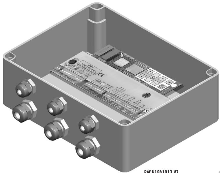
natural_image
3D technical illustration of an electronic device housing with ports and connectors (no visible text or symbols)Réf.N1841013 V2
GB Before installation, please read the safety instructions included in this sheet carefully. Failure to respect these instructions
automatically invalidates the guarantee as well as all liability claims against SOMFY. SOMFY cannot be held responsible for any changes in norms and standards introduced after the publication of this guide.
This box is used to bring into compliance the doors fitted on industrial, commercial premises and garages in relation to the new European standards (NF EN 12445, NEF EN 12453, EN 12978, EN 13241) and French standards (NF P25 362).
68 C Hereby, SOMFY, declares that this equipment is in compliance with the essential requirements and other relevant provisions of Directive 1999/5/EC. A Declaration of Conformity is available at the web address www.somfy.com Heading CE
GB • Settings for motor torque and operation independent for each motor.
- Programming performed using keyboard and pull-down menu.
- System state displayed on LCD.
- Default display for troubleshooting.
- Cycle counter.
• Thermal safety for motor control.
- Speed variation.
- Self-leaning
natural_image
Exterior view of a rectangular electronic device with three mounting points and a 230 mm height dimension (no text or symbols on the device itself)

① Fusible de protection • Protective fuse • Veiligheidszekering • Fusible de protección
② Transformateur • Transformer • Transformator • Transformador
③ Ecran LCD • LCD screen • LCD-scherm • Pantalla de cristal líquido
④ Clavier de programmation • Programming keyboard • Programmeringstoetsenbord • Teclado de programación
⑤ Bornier 230 V • 230 V terminal box • Klemmenstrook 230V • Placa de bornes de 230 V
⑥ Sortie contact auxiliaire • Auxiliary contact output • Uitgang hulpcontact • Salida de contacto auxiliar
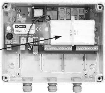
⑦ Raccordement batterie de secours • Backup battery connection • Aansluiting noodbatterij • Conexión de la batería de socorro
⑧ Entrée 24V non utilisée • 24V input not used • 24V ingang niet te gebruiken • Entrada 24 V non utilizada
⑨ Raccordement moteurs et alimentation 24V • Motor and 24V supply connection • Aansluiting motoren en voeding 24V • Conexión de los motores y alimentación de 24 V
⑩ Entrées sécurités et commandes • Safety device and control inputs • Ingangen beveiligingen en bedieningen • Entradas de seguridades y comandos
Domaine d'application • Field of application • Toepassingsgebied • Campo de aplicación
| M1* | 1 ou 2 moteurs courant continu1 or 2 DC motors1 of 2 gelijkstroom motoren1 ó 2 motores de corriente continua |
* Puissance maxi : 150 W / 24V par moteur.
* Max. power : 150W / 24V per motor.
* 1 of 2 gelijkstroom motoren.
* Potencia máxima: 150 W / 24 V por motor.
| Caracteristique • Characteristic • Eigenschappen • Característica | Valeurs • Values • Waarden • Valores |
| Alimentation générale • Power supplyAlgemene voeding • Alimentación general | 220–240 Vac 50–60 Hz |
| Fusible de protection • Protective fuseVeiligheidszekering • Fusible de protección | 5 x 20 – 3,15 AF |
| Alimentation des accessoires avec système de contrôle de surchargePower supply for accessories with overload control deviceVoeding van de accessoires met controlesysteem voor overspanningAlimentación de los accesorios con sistema de control de sobrecarga | 24 Vdc – 1,2 A max |
| Température d’utilisation • Operating temperatureGebruikstemperatuur • Temperatura de utilización | -10° à +50°C • -10° to +50°C-10° tot +50°C • -10° a +50°C |
| Indice de protection • Sun protection factorBeschermingsgraad • Índice de protección | IP55 |
| Classe d’utilisation • Operating classGebruiksklasse • Clase de utilización | 5 < 250 cycles/jour, 5 < 250 cycles/day5 < 250 cycl/dag, 5 < 250 ciclos/día |
| Sécurité thermique pour le contrôle moteurThermal safety for motor controlThermische beveiliging voor motorcontroleSeguridad térmica para el control del motor | OuiYesJaSí |
| Plaque de protection • Protective plateBeveiligingsplaatje • Placa de protección | 1 |
| Borniers débrochables • Detachable tie-point blocksAfneembare klemmenstroken • Placas de bornes desenchufables | 4 |
| Sorties auxiliaires • Auxiliary outputHulpuitgangen • Salidas auxiliares | 1 |
| Nombre de télécommandes mémorisablesNumber of memorised remote controlsAantal te memoriseren afstandsbedieningenNúmero de telecomandos memorizablesClasse II • Class IIClass II • Class II | 32 canaux32 channels32 kanalen32 canales |
Gestions des sécurité • Security management • Veiligheidsbeheer • Gestión de las seguridades
Arrêt d'urgence
Emergency stop
Noodstop
- Pushing the emergency stop button stops the gate entirely. It may be equipped with other safety devices, such as photoelectric cells.
Closure safety devices SEC.F1 and SEC.F2
- Any detection during closure causes stopping then reopening (total or partial, depending on parameter A1). Possibility of connecting 1 or 2 sensors in series on each input.
Opening safety devices SEC.0
- Any detection during opening causes stopping then closure (total or partial, depending on parameter A0). Possibility of connecting a sensor.
- Protection of the Dangerous Movement Area Open to the Public can be validated. This function uses input SEC.F1.Parameter settings activate the following safety devices:
- Detection before opening the gate excludes all movement.
- Detection when closing the gate stops the gate and reopens it.
- When the gate is in movement, 2 outputs control the following devices:
| Control | Contact |
| Area lighting | Dry contact Vmax: 230Vac - Pmax: 150Va |
| Orange light | Output 2 x 15 w (sequence control) |
Signaleringen
According to the parameter settings (parameter Po), the 24V control box has several operating modes: Modes Automatic/Blockage/Senquenced+timed: Compulsory installation of safety accessorie.
| Modes | Operation |
| Automatic | Gate closed, control pulse provokes opening.The gate automatically closes once closing time has expired. |
| Semi-automatic | Gate closed, control pulse provokes opening.When opening, a control pulse has no effect.Gate opened, control pulse provokes closing.When opening, a control pulse reopen the door. |
| Blockage SEC.F1 and SEC.F2 | After the gate is opened, passage in front of the closing security cells closes the gate after a time-delay (parameter t2).If passage in front of cells does not take place, the blockage mode controls gate closure after the automatic closure time-delay (parameter t0). |
| Sequenced | First pulse provokes opening, next pulse provokes stop, next pulse provokes closing etc... |
| Sequenced and timed | Similar to sequenced mode alone but with automatic gate closure after time-delay (parameter t0). |
| Mode with internal keyboard | The "+" key on theinternal keyboardcontrols opening.The "-" key controls closing.⚠️ In this operating mode, no safety device is activated except the emergency stop and torque limitation. |
- Caution! Do not remove the board.
natural_image
3D mechanical assembly diagram showing a component being inserted into two views (top: screwdriver, bottom: bolted case), no text or symbols present.
natural_image
Mechanical assembly diagram showing bolted components and a downward arrow indicating motion (no text or symbols)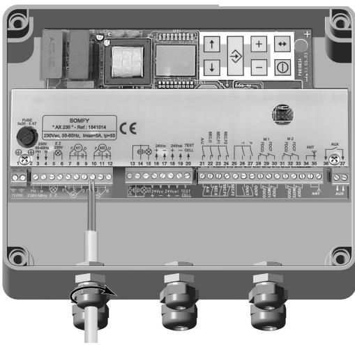
- Insérer et régler la longueur des câbles. Bloquer les presse-étoupes. Attention un mauvais montage des câbles à travers les presse-étoupe peut dégrader l'indice de protection IP55.
- Insert and adjust cable length. Block the cable glands. Caution! Incorrect fitting of the cables à through the glands may downgrade the IP55 protection index.
- Plaats de kabels en stel de lengte hiervan af. Blokkeer de pakkingbussen. Let op, een verkeerde montage van de kabels door de pakkingbussen kan de beschermingsklasse IP55 aantasten.
- Insertar y ajustar la longitud de los cables. Bloquear los prensaestopas. Prestar atención al montaje de los cables a través del prensaestopas dado que un montaje incorrecto puede degradar el índice de protección IP55.
3
The electrical lead must be:
- Reserved exclusively for the axovia,
- Of a minimum section of 1.5 mm ^4
- Properly protected (fuse or circuit breaker rated at 10 A) with a differential device (30 mA),
- Fit a single pole disconnection device standard EN 60335-1.
- Installed according to the current electric safety standards.
De elektrische leiding dient:
Power grid connection (terminals 1 and 2) must be performed as a final operation.
- 1 dry contact (230 Vac - Pmax = 500 VA) is available on tie-point block 6 (contacts 3 and 4).
- 1 supplied contact (24V/1,5 A or 12V/3A) is available on tie-point block 9 (contacts 12 and 14) when using an opener or suction cup.
This contact may be " NC " ou " NO " according to programmed settings.
Hulpcontacten
- Autotest for 24 Vdc photoelectric cells is ensured by shutting down the 24 V power of the emitting cell (terminals 16,17).
Autotest for "reflex" cells is ensured via the terminal "TEST CELL" on the control box (terminal 18).
- 2 boutons • 2 buttons
- 2 knoppen • 2 botones


Use a fixed light for cadenced control.
• Without emergency stop without safety devices
Only modify parameters when the gate is stopped and closed.
After parameter setting, check the good fonctionning of safety accessories.
operation of auto learning Setting into operation
Auto learning is used to measure the stroke, the opening angles of the leaves, to assign the speeds and offsets so that the dor can operate after auto learning.
- Place the doors in intermediate position. Parameter the operating mode 'P0' according to the need (except value 05 which is prohibited) and the auto learning 'P3' to '01'.
- Validate and exit the menu, the display now indicates 'H1'.
- Generate an opening command via the outer command or the radio (after programming it).
- The door leaf(ves) should open and check the covering leaf (cable on M1) starts first, otherwise, check the motor connections. The display indicates 'H2'.
- Wait until the end of opening.
- When the display indicates 'H1', generate a new command to close.
- The door should start closing. The display indicates 'H4'.
• After closing, the auto learning is completed. The display now indicates 'C1'.
Remarks
1 • Learning affects the following parameters: P2, P4, P5, P6, P7, P8, P9, PA, Pb. All these parameters may be modified after learning to make the door movement more precise.
2 • For very fragile doors, it is possible to perform auto learning at a reduced torque by reducing the value of parameters 'P4 and P5' immediately after setting the auto learning parameter 'P3' to '01' and before executing the opening command.
3 • Learning will only be completed after a complete closing movement. A stop during the movement postpones by one cycle the end of learning.
4 • Learning takes place under the control of the user, without cell safety device and without signalisation.
Werking autom. inlezen
Opening and closing time delay
General parameters The values indicated in grey correspond to factory settings.
| Parameter displayed | Operating modes | Value displayed | Fonction |
| P 0 | Mode “On” | 0 | Automatic |
| 1 | Semi-automatic | ||
| 2 | Blockage | ||
| 3 | Sequenced | ||
| 4 | Sequenced and Timed | ||
| 5 | Internal keyboard | ||
| P1 | Time-delay | 0 | With time-delay |
| 1 | Without time-delay | ||
| P2 | 1 or 2 motors | 0 | 2 motors |
| 1 | 1 motor | ||
| P3 | Limit switch operating | 0 | Pressing 'Valid' " activates the autolearning, H1 is displayed in the learning phase (c.f. p17) |
| 1 | |||
| P4 | Motor torque setting 1 | 00 to 10 (10) | Torque setting from 40 to 100% |
| P5 | Motor torque setting 2 | 00 to 10 (10) | Torque setting from 40 to 100% |
| P 6 | High speed setting motor 1&2 | 00 to 10 (05) | HS setting from 00 to 10 |
| P 7 | Low speed setting motor 1&2 | 00 to 10 (04) | LS setting from 00 to 10 |
| P 8 | Low speed position setting | 00 to 05 (02) | Position setting from 0 to 10 |
| P 9 | Pedestrian opening position setting | 00 to 08 (05) | Position setting from 0 to 10 |
| P A | Opening offset setting | 00 to 10 (02) | Position setting from 0 to 10 |
| P b | Closing offset setting | 00 to 10 (04) | Position setting from 0 to 10PB=0 prohibited on swing gate |
| A0 | Activates opening safety device | 0 | Stop |
| 1 | Total reversion | ||
| 2 | Partial reversion | ||
| A1 | Activates closing 1 and 2 safety device | 0 | Stop |
| 1 | Total reversion | ||
| 2 | Partial reversion | ||
| A2 | Autotest opening safety device | 0 | Without autotest |
| 1 | With autotest | ||
| A3 | Cell autotest by shutting down power supplyOn closing safety device 1 | 0 | Without autotest |
| 1 | With autotest |
General parameters The values indicated in grey correspond to factory settings.
| Parameter displayed | Operating modes | Value displayed | Function |
| A4 | Cell autotest by shutting down power supplyOn closing safety device 2 | 01 | Without autotestWith autotest |
| A5 | Reflex or edge sensor cell autotestOn closing safety device 1 | 01 | Without autotestWith autotest |
| A6 | Reflex or edge sensor cell autotestOn closing safety device 2 | 01 | Without autotestWith autotest |
| A7 | DMAOP on entranceclosing safety device 1 | 01 | Without DMAOPWith DMAOP |
| F 0 | Memorisation of radio codesMaximum 32 channels | 0123 | Total controlPartial controlAuxiliaryAll radio codes erasedby pressing VALIDfor 5 s |
| F 1 | Closing pulse | 01 | Without closing pulseWith closing pulse |
| F 2 | Lock shot/suction cup | 0123 | Lock shot 12VLock shot 24VSuction cupTimer contact |
| F 3 | Selection for auxiliary output function | 012345 | Contact pour minuterieOpen gate indicatorMonostable radio channelDualstable radio channelArea lightIntrusion alarm by cell concealed |
| F 4 | Keyboard lock | 55XX | Keyboard unlockedKeyboard locked, Code 55to unlock |
| F 5 | Accessory consumptionvisualisation | XX | Current in A |
| U 0U 1U 2 | Cycle counter | XXXXXXX | Tens and unitsThousands and hundredsHundreds of thousand and tens of thousand |
Time delay setting The values indicated in grey correspond to factory settings.
| Parameter displayed | Delay setting | Value displayed | Function |
| t 0 | Closing time (free passage) | 00 to 99 s (05) | (1 s increment) |
| t 1 | Zone lighted time after end of cycle | 00 to 10 min (00) | (1 min increment) |
| t 2 | Waiting time after passage in front of cell | 00 to 99 s (00) | (1 s increment) |
| t 3 | Motor 1 and 2 ramp rate time | 00 to 02 s (02) |
Operational control and troubleshooting
| Display | Meaning | Display | Meaning |
| C 1 | Control stand-by | E 1 | Opening safety device default (always contact) |
| C 2 | Gate opening | E 2 | Closing 1 safety device default (always contact) |
| C 3 | Closing stand-by | E 3 | Closing 2 safety device default (always contact) |
| C 4 | Gate closing | E 4 | Opening safety device default (default autotest) |
| C 5 | DMAOP safety device blanked | E 5 | Closing 1 safety device default (default autotest) |
| C 6 | Cell opening safety device blanked | E 6 | Closing 2 safety device default (default autotest) |
| C 7 | Cell closing safety device blanked | E 7 | Overload 24V, intensity overrun |
| C 8 | Forced movement via keyboard | E 8 | Intrusion default |
| C 9 | Emergency stop triggered | E 9 | Motor thermal safety device |
| C A | Safety device autotest in progress | E A | Motor slipping default |
| C b | Permanent control validated | E b | Limit switch default |
| C C | Time delay stand-by shutdown before reversion | ||
| C d | Operation in battery mode |


www.somfy.com
Australia :
SOMFY PTY LTD
www.somfy.com.au
Austria :
SOMFY GesmbH
www.somfy.at
Belgium :
NV SOMFY SA
www.somfy.be
Brasil :
SOMFY BRASIL STDA
www.somfy.com
Canada :
SOMFY ULC
www.somfy.com
Cyprus :
SOMFY MIDDLE EAST
www.somfy.com
Czech Republic :
SOMFY Spol s.r.o.
www.somfy.com
Denmark :
SOMFY AB DENMARK
www.Somfy.dk
Finland :
SOMFY AB FINLAND
www.Somfy.fi
France :
SOMFY FRANCE
www.somfy.fr
Germany :
SOMFY GmbH
www.somfy.de
Greece :
SOMFY HELLAS
www.somfy.com
Hong Kong :
SOMFY Co. Ltd
www.somfy.com
Hungary :
SOMFY Kft
www.somfy.com
India :
SOMFY INDIA PVT Ltd
www.somfy.com
Italy :
SOMFY ITALIA s.r.l
www.somfy.it
Japan :
SOMFY KK
www.somfy.co.jp
Lebanon :
cf. Cyprus - SOMFY
MIDDLE EAST
www.somfy.com
Mexico :
SOMFY MEXICO SA de CV
www.somfy.com.mx
Morocco :
SOMFY MAROC
www.somfy.com
Netherlands :
SOMFY BV
www.somfy.nl
Norway :
SOMFY NORWAY
www.Somfy.no
Poland :
SOMFY SP Z.0.0
www.somfy.pl
Portugal : cf. Spain -
SOMFY ESPANA SA
www.somfy.com
Russia : cf. Germany -
SOMFY GmbH
www.somfy.de
Singapore :
SOMFY PTE LTD
www.somfy.com.sg
Slovaquia : cf. Czech
Republic -
SOMFY Spol s.r.o.
www.somfy.com
South Korea :
SOMFY J00
www.somfy.co.kr
Spain :
SOMFY ESPANA SA
www.somfy.com
Sweden :
SOMFY AB
www.Somfy.se
Switzerland :
SOMFY A.G.
www.somfy.ch
Taiwan :
SOMFY TAIWAN
www.somfy.com
United Kingdom :
SOMFY LTD
www.somfy.co.uk
United States :
SOMFY SYSTEMS Inc
www.somfysystems.com
CE

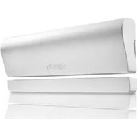


Brand : SOMFY
Model : 24 V
Category : Shutter and blind motors