
DH 40MRY - Drill HITACHI - Free user manual and instructions
Find the device manual for free DH 40MRY HITACHI in PDF.


| Product Type | Rotary Hammer (Rotary Hammer Drill) |
| Brand | Hitachi |
| Model | DH 40MRY |
| Rated Voltage | 120 V |
| Frequency | 60 Hz |
| Rated Current | 9.2 A |
| Drilling Capacity (Concrete) | 40 mm |
| Core Drilling Capacity | 105 mm |
| No-Load Speed (Rotations) | 240 - 480 rpm |
| Impact Rate | 1320 - 2650 bpm |
| Weight | 6.8 kg |
| Chuck Type | SDS max |
| Double Insulation | Yes |
| Operating Modes | Rotation + Hammer, Hammer Only |
| Speed Adjustment | Electronic, 6 positions |
| Side Handle | Included |
| Included Accessories | Carrying case, side handle, bull point, grease |
| Motor Maintenance | Carbon brush replacement |
| Grease Change | Every 6 months, Hitachi Grease A |
| Cleaning | Soft cloth with soapy water |
| Safety | Selector lock, restart protection |
Frequently Asked Questions - DH 40MRY HITACHI
User questions about DH 40MRY HITACHI
0 question about this device. Answer the ones you know or ask your own.
Ask a new question about this device
Download the instructions for your Drill in PDF format for free! Find your manual DH 40MRY - HITACHI and take your electronic device back in hand. On this page are published all the documents necessary for the use of your device. DH 40MRY by HITACHI.
USER MANUAL DH 40MRY HITACHI
natural_image
Technical line drawing of a mechanical drill bit with threaded shaft and bolt (no text or symbols)SAFETY INSTRUCTIONS AND INSTRUCTION MANUAL
WARNING
IMPROPER OR UNSAFE use of this power tool can result in death or serious bodily injury!
This manual contains important information about product safety. Please read and understand this manual BEFORE operating the power tool. Please keep this manual available for other users and owners before they use the power tool. This manual should be stored in safe place.
INSTRUCTIONS DE SECURITE ET MODE D'EMPLOI
AVERTISSEMENT
IMPORTANT SAFETY INFORMATION .... 3
MEANINGS OF SIGNAL WORDS 3
SAFETY
GENERAL SAFETY RULES 3
SPECIFIC SAFETY RULES AND SYMBOLS ...... 4
DOUBLE INSULATION FOR SAFER OPERATION .... 5
FUNCTIONAL DESCRIPTION
NAME OF PARTS 6
SPECIFICATIONS 7
Page
ASSEMBLY AND OPERATION
APPLICATIONS 7
IMPORTANT SAFETY INFORMATION
Read and understand all of the safety precautions, warnings and operating instructions in the Instruction Manual before operating or maintaining this power tool.
Most accidents that result from power tool operation and maintenance are caused by the failure to observe basic safety rules or precautions. An accident can often be avoided by recognizing a potentially hazardous situation before it occurs, and by observing appropriate safety procedures.
Basic safety precautions are outlined in the "SAFETY" section of this Instruction Manual and in the sections which contain the operation and maintenance instructions.
Hazards that must be avoided to prevent bodily injury or machine damage are identified by WARNINGS on the power tool and in this Instruction Manual.
NEVER use this power tool in a manner that has not been specifically recommended by HITACHI.
MEANINGS OF SIGNAL WORDS
WARNING indicates a potentially hazardous situations which, if ignored, could result in death or serious injury.
CAUTION indicates a potentially hazardous situations which, if not avoided, may result in minor or moderate injury, or may cause machine damage.
NOTE emphasizes essential information.
SAFETY
GENERAL SAFETY RULES

WARNING:
Read all instructions
Failure to follow all instructions listed below may result in electric shock, fire and/or serious injury.
The term “power tool” in all of the warnings listed below refers to your mains-operated (corded) power tool or battery-operated (cordless) power tool.
SAVE THESE INSTRUCTIONS
1) Work area safety
a) Keep work area clean and well lit.
Cluttered or dark areas invite accidents.
b) Do not operate power tools in explosive atmospheres, such as in the presence of flammable liquids, gases or dust.
Power tools create sparks which may ignite the dust of fumes.
c) Keep children and bystanders away while operating a power tool.
Distractions can cause you to lose control.
2) Electrical safety
a) Power tool plugs must match the outlet.
Never modify the plug in any way.
Do not use any adapter plugs with earthed (grounded) power tools.
Unmodified plugs and matching outlets will reduce risk of electric shock.
b) Avoid body contact with earthed or grounded surfaces such as pipes, radiators, ranges and refrigerators.
There is an increased risk of electric shock if your body is earthed or grounded.
c) Do not expose power tools to rain or wet conditions.
Water entering a power tool will increase the risk of electric shock.
d) Do not abuse the cord. Never use the cord for carrying, pulling or unplugging the power tool.
Keep cord away from heat, oil, sharp edges or moving parts.
Damaged or entangled cords increase the risk of electric shock.
e) When operating a power tool outdoors, use an extension cord suitable for outdoor use.
Use of a cord suitable for outdoor use reduces the risk of electric shock.
3) Personal safety
a) Stay alert, watch what you are doing and use common sense when operating a power tool. Do not use a power tool while you are tired or under the influence of drugs, alcohol or medication.
A moment of inattention while operating power tools may result in serious personal injury.
b) Use safety equipment. Always wear eye protection.
Safety equipment such as dust mask, non-skid safety shoes, hard hat, or hearing protection used for appropriate conditions will reduce personal injuries.
c) Avoid accidental starting. Ensure the switch is in the off position before plugging in.
Carrying power tools with your finger on the switch or plugging in power tools that have the switch on invites accidents.
d) Remove any adjusting key or wrench before turning the power tool on.
A wrench or a key left attached to a rotating part of the power tool may result in personal injury.
e) Do not overreach. Keep proper footing and balance at all times.
This enables better control of the power tool in unexpected situations.
f) Dress properly. Do not wear loose clothing or jewellery. Keep your hair, clothing and gloves away from moving parts.
Loose clothes, jewellery or long hair can be caught in moving parts.
g) If devices are provided for the connection of dust extraction and collection facilities, ensure these are connected and properly used.
Use of these devices can reduce dust-related hazards.
4) Power tool use and care
a) Do not force the power tool. Use the correct power tool for your application.
The correct power tool will do the job better and safer at the rate for which it was designed.
b) Do not use the power tool if the switch does not turn it on and off.
Any power tool that cannot be controlled with the switch is dangerous and must be repaired.
c) Disconnect the plug from the power source and/or the battery pack from the power tool before making any adjustments, changing accessories, or storing power tools.
Such preventive safety measures reduce the risk of starting the power tool accidentally.
d) Store idle power tools out of the reach of children and do not allow persons unfamiliar with the power tool or these instructions to operate the power tool.
Power tools are dangerous in the hands of untrained users.
e) Maintain power tools. Check for misalignment or binding of moving parts, breakage of parts and any other condition that may affect the power tools operation.
If damaged, have the power tool repaired before use.
Many accidents are caused by poorly maintained power tools.
f) Keep cutting tools sharp and clean.
Properly maintained cutting tools with sharp cutting edges are less likely to bind and are easier to control.
g) Use the power tool, accessories and tool bits etc., in accordance with these instructions and in the manner intended for the particular type of power tool, taking into account the working conditions and the work to be performed.
Use of the power tool for operations different from intended could result in a hazardous situation.
5) Service
a) Have your power tool serviced by a qualified repair person using only identical replacement parts.
This will ensure that the safety of the power tool is maintained.
-WARNING-
To reduce the risk of injury, user must read instruction manual.
SPECIFIC SAFETY RULES AND SYMBOLS
-
Hold tools by insulated gripping surfaces when performing an operation where the cutting tool may contact hidden wiring or its own cord. Contact with a "live" wire will make exposed metal parts of the tool "live" and shock the operator.
-
ALWAYS wear ear protections.

Exposure to noise can cause hearing loss.
-
Use auxiliary handles supplied with the tool. Loss of control can cause personal injury.
-
NEVER touch the tool bit with bare hands after operation.
-
NEVER wear gloves made from materials likely to roll up such as cotton, wool, cloth or string, etc.
-
ALWAYS attach the side handle and securely grip the Rotary Hammer.
-
NEVER touch moving parts. NEVER place your hands, fingers or other body parts near the tool's moving parts.
-
NEVER operate without all guards in place.
NEVER operate this tool without all guards or safety features in place and in proper working order. If maintenance or servicing requires the removal of a guard or safety feature, be sure to replace the guard or safety feature before resuming operation of the tool.
9. Use right tool.
Don't force small tool or attachment to do the job of a heavy-duty tool.
Don't use tool for purpose not intended —for example— don't use circular saw for cutting tree limbs or logs.
10. NEVER use a power tool for applications other than those specified.
NEVER use a power tool for applications other than those specified in the Instruction Manual.
11. Handle tool correctly.
Operate the tool according to the instructions provided herein. Do not drop or throw the tool.
NEVER allow the tool to be operated by children, individuals unfamiliar with its operation or unauthorized personnel.
12. Keep all screws, bolts and covers tightly in place.
Keep all screws, bolts, and plates tightly mounted. Check their condition periodically.
13. Do not use power tools if the plastic housing or handle is cracked.
Cracks in the tool's housing or handle can lead to electric shock. Such tools should not be used until repaired.
14. Blades and accessories must be securely mounted to the tool.
Prevent potential injuries to yourself or others. Blades, cutting implements and accessories which have been mounted to the tool should be secure and tight.
15. Keep motor air vent clean.
The tool's motor air vent must be kept clean so that air can freely flow at all times. Check for dust build-up frequently.
16. Operate power tools at the rated voltage.
Operate the power tool at voltages specified on its nameplate.
If using the power tool at a higher voltage than the rated voltage, it will result in abnormally fast motor revolution and may damage the unit and the motor may burn out.
17. NEVER use a tool which is defective or operating abnormally.
If the tool appears to be operating unusually, making strange noises, or otherwise appears defective, stop using it immediately and arrange for repairs by a Hitachi authorized service center.
18. NEVER leave tool running unattended. Turn power off.
Don't leave tool until it comes to a complete stop.
19. Carefully handle power tools.
Should a power tool be dropped or struck against hard materials inadvertently, it may be deformed, cracked, or damaged.
20. Do not wipe plastic parts with solvent.
Solvents such as gasoline, thinner benzine, carbon tetrachloride, and alcohol may damage and crack plastic parts. Do not wipe them with such solvents.
Wipe plastic parts with a soft cloth lightly dampened with soapy water and dry thoroughly.
- ALWAYS wear eye protection that meets the requirement of the latest revision of ANSI Standard Z87.1.

22. ALWAYS be careful with buried object such as an underground wiring.
Touching live wiring or electric cable with this tool may result in electric shock.
Confirm before use whether hidden objects are present, such as electric cables within the wall, floor or ceiling.
23. Definitions for symbols used on this tool
V ...... volts
Hz ...... hertz
A ...... amperes
n_0 ...... no load speed
W ...... watt
☐...... Class II Construction
---/min ..... revolutions per minute
\~ ...... Alternating current
To ensure safer operation of this power tool, HITACHI has adopted a double insulation design. "Double insulation" means that two physically separated insulation systems have been used to insulate the electrically conductive materials connected to the power supply from the outer frame handled by the operator.
Therefore, either the symbol "☐ for the words "Double insulation" appear on the power tool or on the nameplate.
Although this system has no external grounding, you must still follow the normal electrical safety precautions given in this Instruction Manual, including not using the power tool in wet environments.
To keep the double insulation system effective, follow these precautions:
○ Only HITACHI AUTHORIZED SERVICE CENTER should disassemble or assemble this power tool, and only genuine HITACHI replacement parts should be installed.
○ Clean the exterior of the power tool only with a soft cloth moistened with soapy water, and dry thoroughly.
Never use solvents, gasoline or thinners on plastic components; otherwise the plastic may dissolve.
SAVE THESE INSTRUCTIONS
AND
MAKE THEM AVAILABLE TO OTHER USERS
AND
OWNERS OF THIS TOOL!
FUNCTIONAL DESCRIPTION
NOTE:
The information contained in this Instruction Manual is designed to assist you in the safe operation and maintenance of the power tool.
NEVER operate, or attempt any maintenance on the tool unless you have first read and understood all safety instructions contained in this manual.
Some illustrations in this Instruction Manual may show details or attachments that differ from those on your own power tool.
NAME OF PARTS

Fig. 1
SPECIFICATIONS
| Motor Single-Phase, Series Commutator | Motor. |
| Power Source Single-Phase, 120 V 60 Hz | |
| Current 9.2 A | |
| Capacity Drill Bit: 1-9/16" (40 mm) | Core Bit: 4-1/8" (105 mm) |
| No-Load Speed 240 – 480/min | |
| Full-load Blow 1,320 – 2,650/min | |
| Weight 15.0 lbs (6.8 kg) |
ASSEMBLY AND OPERATION
APPLICATIONS
Rotation and hammering function
○ Drilling anchor holes
○ Drilling holes in concrete
Hammering function only
○ Crushing concrete, chipping, digging, and squaring (by applying optional accessories)
PRIOR TO OPERATION
- Power source
Ensure that the power source to be utilized conforms to the power source requirements specified on the product nameplate.
- Power switch
Ensure that the switch is in the OFF position. If the plug is connected to a receptacle while the switch is in the ON position, the power tool will start operating immediately and can cause serious injury.
- Extension cord
When the work area is far away from the power source, use an extension cord of sufficient thickness and rated capacity. The extension cord should be kept as short as practicable.

WARNING:
Damaged cord must be replaced or repaired.
- Check the receptacle
If the receptacle only loosely accepts the plug, the receptacle must be repaired. Contact a licensed electrician to make appropriate repairs.
If such a fautly receptacle is used, it may cause overheating, resulting in a serious hazard.
- Confirming condition of the environment:
Confirm that the work site is placed under appropriate conditions conforming to prescribed precautions.
- How to install tool
CAUTION:
For tools such as a drill bit and a bull point, use only Hitachi genuine parts.
(1) Clean, then smear the tool shank with the grease provided in the green tube.
(2) To attach the tool (SDS max shank), insert it into the hole until it contacts the innermost end of the hole as illustrated in Fig. 2.
If you continue to turn the tool with slight pressure, you can feel a spot where there is a hitch. At that spot, pull the grip to the direction of an arrow mark and insert the tool all the way until it hits the innermost end.
Releasing the grip reverts the grip and secures the tool in place.

Fig. 2
(3) Pull the tool to make sure it is locked completely.
(4) To remove the tool, fully pull the grip in the direction of the arrow and pull out the tool.
7. Regulating the number of rotations and hammering (Fig. 3)
This Rotary Hammer is equipped with a built-in electronic control circuit that can adjust and
regulate the number of rotations and times of hammering. This Rotary Hammer can be used by adjusting the dial, depending upon the contents of operation, such as boring holes into fragile materials, chipping, centering, etc.
The scale '1' of the dial is designed for a minimum speed with the number of 240 rotations per minute and 1,320 times of blow per minute. The scale '6' is designed for a maximum speed with the number of 480 rotations per minute and 2,650 times of blow per minute.
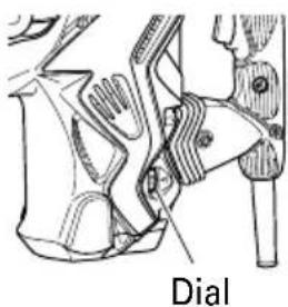
Fig. 3
CAUTION:
Do not adjust the dial during operation. Doing so can result in injury because the Rotary Hammer must be held by only one hand, disabling the steady control of the Rotary Hammer.
HOW TO USE
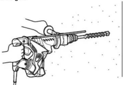
- How to drill holes (Fig. 4)
(1) Pull the switch trigger after applying the drill bit tip to the drilling position.
(2) It is unnecessary to forcibly press the Rotary Hammer main body. It is sufficient to slightly press the rotary hammer to an extent that clips are freely discharged.
natural_image
Line drawing of a hand holding a drill bit with a coiled drill bit (no text or symbols)Fig. 4
CAUTION:
Although this machine is equipped with a safety clutch, if the drill bit becomes bound in concrete or other material, the resultant stoppage of the drill bit could cause the machine body to turn in reaction. Ensure that the main handle and side handle are gripped firmly during operation.
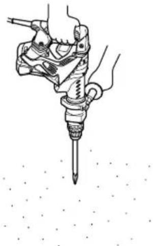
- How to chisel or crush (Fig. 5)
By applying the tool tip to the chiseling or crushing position, operate the rotary hammer by utilizing its empty weight. Forcible pressing or thrusting is unnecessary.
natural_image
Illustration of a hand using a screwdriver to tighten a bolt, with no text or symbols present.Fig. 5
- When drilling at "rotation + hammering"
CAUTION:
If you switch the selector lever during motor rotation, the tool can start to rotate abruptly, resulting in unexpected accidents. Be sure to switch the selector lever when the motor is at a complete stop.
(1) Switching to "rotation + hammering"
(a) Push the button, release lock and turn the selector lever clockwise.
(b) Align ▲ of the selector lever and IT of the lever holder as illustrated in Fig. 6.
(c) Release the button to lock the selector lever.

Fig. 6
NOTE:
Turn the selector lever (do not push the button) to check if it is completely locked and make sure that it does not turn.
- When chipping and shredding at "hammering":
CAUTION:
If the selector lever is switched during motor rotation, the tool can start to rotate abruptly, resulting in unexpected accidents. Make sure to switch the selector lever when the motor is at a complete stop.
If the bull point or cold chisel is used at the position of "rotation + hammering", the tool can start to rotate, resulting in unexpected accidents. Make sure that they are used at the positon of "hammering".
(1) Switching to "hammering"
(a) Push the button, release lock and turn the selector lever counterclockwise.
(b) Align ▲ of the selector lever and T of the lever holder as illustrated in Fig. 7.
(c) Release the button to lock the selector lever.

Fig. 7
NOTE:
Turn the selector lever (do not push the button) to check if it is completely locked and make sure that it does not turn.
(2) When fixing working positions of tools such as cold chisel, etc.,
(a) Push the button, release lock and turn the selector lever.
Align ▲ of the selector lever and Ⓞ of the lever holder as illustrated in Fig. 8.
(b) Release the button to lock the selector lever.

Fig. 8
(c) Turn the grip as illustrated in Fig. 9 and fix the tool to the desired working direction.
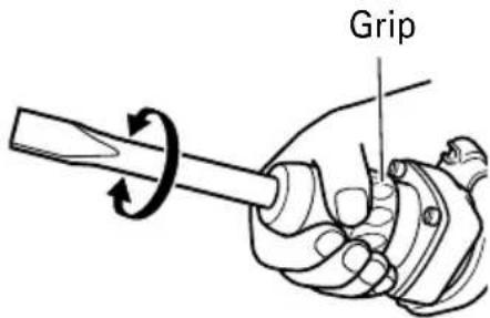
Fig. 9
(d) Switch the selector lever to "hammering" according to the procedures mentioned in the above item (1) and secure the position of the tool.
- Install the stopper (Fig. 10)
(1) Loosen the side handle and insert the straight portion of the stopper into the handle bolt hole from the front cover.
(2) Loosen the side handle, move the stopper to the specified position and rotate the grip of the side handle clockwise to fix the stopper.
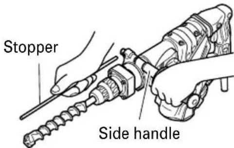
Fig. 10
- Warming up (Fig. 11)
The grease lubrication system in this unit may require warming up in cold regions.
Position the end of the bit so makes contact with the concrete, turn on the switch and perform the warming up operation. Make sure that a hitting sound is produced and then use the unit.
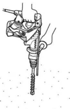
natural_image
Illustration of a hand using a drill bit to measure a screwdriver (no text or symbols present)Fig. 11

CAUTION:
When the warming up operation is performed, hold the side handle and the main body securely with both hands to maintain a secure grip and be careful not to twist your body by the jammed drill bit.
- How to use the drill bit (taper shank) and the taper shank adaptor.
(1) Install drill bit with taper shank in the taper shank adaptor. (Fig. 12)
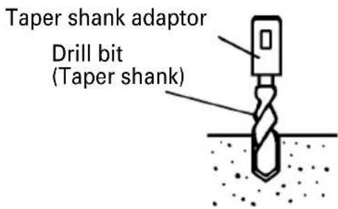
Fig. 12
(2) Turn the power on and drill a base hole.
(3) After cleaning out dust with a syringe, attach the plug to the anchor tip and drive in the anchor with a manual hammer.
(4) To remove the drill bit with taper shank, insert a cotter into the slot of the taper shank adaptor, place supports under the Rotary Hammer and tap the cotter with a manual hammer. (Fig. 13)
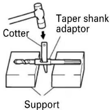
Fig. 13
USING DRILL CHUCK, CHUCK ADAPTOR
Note that this machine can be used at "rotation only" if separately sold parts such as drill chuck and chuck adaptor are attached. Use it with the selector lever positioned at "rotation + hammering".

WARNING:
During operation, be sure to grip the handle and the side handle firmly to prevent your body from swaying.
(1) Switching to "rotation + hammering" For switching to "rotation + hammering", follow the same procedures mentioned in [3. When drilling at "rotation + hammering"] in Page 8.
(2) Attaching chuck adaptor to drill chuck (Fig. 14)
(a) Attach the chuck adaptor to the drill chuck.
(b) The SDS max shank of the chuck adaptor is equivalent to the drill bit. Therefore, follow the same procedure as [6. How to install tool] in Page 7 for attaching and detaching.

Fig. 14
(3) Drilling
(a) Even if you apply more-than-required pressure to the machine body, drilling can never be performed as quickly as you expect. Applying more force or pressure to the machine body than what is needed, on the contrary, damages the drill tip, resulting in the declined working efficiency and shortened life of this machine.
(b) A drill can snap sometimes when drilling is almost finished. It is important to relax your thrusting pressure when drilling is nearing the end.
HOW TO USE THE CORE BIT
When boring penetrating large hole use the core bit. At that time use with the center pin and the core bit shank provided as optional accessories.
- Mounting

CAUTION:
Be sure to turn power OFF and disconnect the plug from the receptacle.
(1) Mount the core bit to the core bit shank. (Fig. 15) Lubricate the thread of the core bit shank to facilitate disassembly.

Fig. 15
(2) Mount the core bit shank to the Rotary Hammer. (Fig. 16)

natural_image
Illustration of a hand holding a cylindrical object above a mechanical component (no text or symbols)Fig. 16
(3) Insert the center pin into the guide plate until it stops.
(4) Engage the guide plate with the core bit, and turn the guide plate to left or right so that it does not fall even if it faces downward. (Fig. 17)
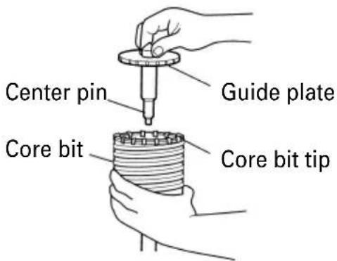
Fig. 17
- How to bore (Fig. 18)
(1) Connect the plug to the receptacle.
(2) A spring is installed in the center pin. Push it lightly to the wall or the floor straight. Connect all over the surface of the core bit tip and start operating.
(3) When boring about 3/16" (5 mm) in depth the position of the hole will establish. Bore after that removing the center pin and the guide plate from core bit.
(4) Application of excessive force will not only expedite the work, but will deteriorate the tip edge of the drill bit, resulting in reduced service life of the rotary hammer.

natural_image
Illustration of a hand using a rotary hammer to measure a drill bit (no text or symbols present)Fig. 18
CAUTION:
When removing the center pin and the guide plate, turn OFF the switch and disconnect the plug from the receptacle.
3. Dismounting (Fig. 19)
Remove the core bit shank from the rotary hammer and strike the head of the core bit shank strongly two or three times with a manual hammer holding the core bit, then the thread becomes loose and the core bit can be removed.

Fig. 19
MAINTENANCE AND INSPECTION
WARNING:
Be sure to switch power OFF and disconnect the plug from the receptacle during maintenance and inspection.
- Inspecting the drill bits
Since use of a dull tool will cause motor malfunctioning and degraded efficiency, replace the drill bit with a new one or resharpening without delay when abrasion is noted.
- Inspecting the screws
Regularly inspect all screws and ensure that they are properly tightened. Should any of the screws be loose, retighten them immediately.
WARNING:
Using this Rotary Hammer with loosen screws is extremely dangerous.
- Maintenance of the motor
The motor unit winding is the very "heart" of the power tool. Exercise due care to ensure the winding does not become damaged and/or wet with oil or water.
- Inspecting the carbon brushes: (Fig. 20)
The motor employs carbon brushes which are consumable parts. When they become worn to or near “wear limit”, it could result in motor trouble. When an auto-stop carbon brush is equipped, the motor will stop automatically. At that time, replace both carbon brushes with new ones which have the same carbon brush Nos. shown in the figure. In addition, always keep carbon brushes clean and ensure that they slide freely within the brush holders.
CAUTION:
Using this Rotary Hammer with a carbon brush which is worn in excess of the wear limit will damage the motor.

Fig. 20
NOTE:
Use HITACHI carbon brush No.73 indicated in Fig. 20
○ Replacing carbon brushes:
(For parts name, refer to Fig. 1)
Loosen the two set screws and remove the tail cover. Remove the brush caps and carbon brushes. After replacing the carbon brushes, tighten the brush caps securely and to install the tail cover with securely tightening two set screws.
- How to replase grease
This machine is full air-tight construction to protect against dust and to prevent lubricant leakage. Therefore, the machine can be used without lubrication for long periods. Replace the grease as described below.
○ Grease replacement period
After purchase, replace grease after every 6 months of usage. Ask for grease replacement at the nearest HITACHI Authorized Service Center. Proceed for replacement of grease.
○ Grease replenishment
CAUTION:
Before replenishing the grease, turn the power off and pull out the power plug.
(1) Remove the crank cover and wipe off the grease inside.
(2) Apply 1.0 oz (30 g) of HITACHI Electric Hammer Grease A (standard accessory, contained in tube) to the crank case.
(3) After replenishing the grease, install the crank cover securely.
Crank cover

natural_image
Technical line drawing of a mechanical tool with no visible text or symbolsFig. 21
NOTE:
The HITACHI Electric Hammer Grease A is of the lower viscosity type. When the supplied grease tube is consumed, purchase from a HITACHI Autorized Service Center.
6. Service and repairs
All quality power tools will eventually require servicing or replacement of parts because of wear from normal use. To assure that only authorized replacement parts will be used, all service and repairs must be performed by a HITACHI AUTHORIZED SERVICE CENTER, ONLY.
7. Service parts list
A: Item No.
B: Code No.
C: No. Used
D: Remarks

CAUTION:

Repair, modification and inspection of Hitachi Power Tools must be carried out by a Hitachi Authorized Service Center.
This Parts List will be helpful if presented with the tool to the Hitachi Authorized Service Center when requesting repair or other maintenance.
In the operation and maintenance of power tools, the safety regulations and standards prescribed in each country must be observed.
MODIFICATIONS:
Hitachi Power Tools are constantly being improved and modified to incorporate the latest technological advancements.
Accordingly, some parts (i.e. code numbers and/or design) may be changed without prior notice.
ACCESSORIES

WARNING:
ALWAYS use Only authorized HITACHI replacement parts and accessories. NEVER use replacement parts or accessories which are not intended for use with this tool. Contact HITACHI if you are not sure whether it is safe to use a particular replacement part or accessory with your tool.
The use of any other attachment or accessory can be dangerous and could cause injury or mechanical damage.
NOTE:
Accessories are subject to change without any obligation on the part of the HITACHI.
STANDARD ACCESSORIES
| (1) Case (Molded plastic) (Code No. 326489) | 1 |
| (2) Side Handle (Code No. 313078) | 1 |
| (3) Stopper (Code No. 971786) | 1 |
| (4) Hammer Grease A (Code No. 981840) | 1 |
OPTIONAL ACCESSORIES.....sold separately
| For accessories in detail please call HITACHI AT 1-800-59-TOOLS |
- Through-hole drilling (Rotation + Hammering)

(1) Drill bit (SDS-max shank)
| External dia. | Overall lenght Code No. | |
| 5/8" (340 (16 mm) 21 | 13-3/8" mm) | 313448 |
| -1/4" (540 mm) | 313456 | |
| 3/4" (340 (19 mm) 21 | 13-3/8" mm) | 313449 |
| -1/4" (540 mm) | 313457 | |
| 7/8" (320 (22 mm) 20 | 12-5/8" mm) | 313450 |
| -15/32" (520 mm) | 313458 | |
| 1" (320 (25 mm) 20 | 12-5/8" mm) | 313451 |
| -15/32" (520 mm) | 313459 | |
| 1-1/8" (370 (28 mm) 22 | 14-9/16" mm) | 313452 |
| -7/16" (570 mm) | 313460 | |
| 1-1/4" (370 mm) | 14-9/16" | 313453 |
| (570 mm) | 313461 | |
| 1-1/2" (370 mm) | 14-9/16" | 313454 |
| (570 mm) | 313462 | |
| 1-9/16" (370 mm) | 14-9/16" | 313455 |
| (570 mm) | 313463 | |
- Anchor hole drilling (Rotation + Hammering)
Adaptor for SDS-plus shank bit

(1) Drill Bit (SDS-plus shank)
(2) Adaptor for SDS-plus shank bit (SDS max shank)
Code No. 313465
- Large-dia. hole boring (Rotation + Hammering)
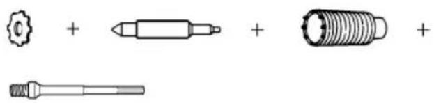
natural_image
Illustration of four different types of screw or tool packages: a gear, a cylindrical component, a threaded bolt, and a standard mechanical part (no text or symbols present)(Guide plate)
| Code No. |
| 985388 |
| 955169 |
(1) Center pin
| Code No. |
| 955165 |
(2) Core bit
| External dia. |
| 2" (50 mm) |
| 4-1/8" (105 mm) |
(3) Core bit shank (SDS max shank)
| Code No. |
| 313467 |
- Drilling holes....For drilling metals and wooden materials

- Bolt plaching operation with Chemical Anchor (Rotation + Hammering)

natural_image
Simple line drawing of a cylindrical object and a mechanical tool (no text or symbols)(Standard socket on the market)
(1) Chemical Anchor Adaptor (SDS max shank)
| Square dimensions of the side of the socket installation | Code No. |
| 1/2" (12.7 mm) 313469 | |
| 3/4" (19.0 mm) 313470 |
- Crushing (Hammering)

(1) Bull point
| Overall length Code No. | |
| 11" (280 mm) 313471 | |
| 15-3/4" (400 mm) 313472 |
- Groove digging and edging (Hammering)

(1) Cold chisel
| Overall length Code No. |
| 11" (280 mm) 313473 |
| 15-3/4" (400 mm) 313474 |
8. Asphalt cutting (Hammering)

(1) Cutter
| Overall length Width Code No. | ||
| 15-3/4" (400 mm) | 1-31/32" (50 mm) 31 | 3475 |
9. Digging
(1) Scoop
Code No. 313476

10. Surface Roughing (Hammering)

natural_image
Technical line drawing of a hexagonal bolt and a cylindrical tool (no text or symbols)(1) Bushing Tool
Code No. 313477
(2) Shank
| Overall length Code No. | |
| 8-21/32" (220 mm) 31 | 3479 |
11. Tamping (Hammering)

natural_image
Technical line drawing of a mechanical component with a circular housing and a cylindrical shaft (no text or symbols)(1) Rammer
Code No. 313478
(2) Shank
| Overall length Code No. | |
| 8-21/32" (220 mm) 31 | 3479 |
12. Syringe (for chip removal)
Code No. 320859

- Hammer grease A
1.1 lbs (500 g) (in a can) Code No. 980927
0.15 lbs (70 g) (in a green tube) Code No. 308471
NOTE:
Specifications are subject to change without any obligation on the part of the HITACHI.
INFORMATIONS IMPORTANTES DE SÉCURITÉ
natural_image
Line drawing of a hand holding a mechanical tool, possibly a drill bit or trigger, with no visible text or symbols.Fig. 4
PRECAUTION:
natural_image
Illustration of a hand holding a screwdriver with a pointed tip (no text or symbols)Fig. 5
(c) Turn the grip as illustrated in Fig. 9 and fix the tool to the desired working direction.
Attache coulissante

natural_image
Illustration of a hand holding a tool with a circular motion arrow indicating rotation (no text or symbols)Fig. 9
natural_image
Illustration of a hand using a tool to tighten a screw, no text or symbols presentFig. 11
PRECAUTIÓN:
Fig. 13
UTILISATION DU MANDRIN PORTE-FORET ET DU RACCORD DE MANDRIN
natural_image
Illustration of a hand holding a cylindrical object above a tool, no text or symbols presentFig. 16
natural_image
Line drawing of a hand using a drill bit to measure a cylindrical tool (no text or symbols present)Fig. 18
PRECAUTION:
- Broyage (Percussion)

(1) Point de broyage
| Longueur totale No. de code | |
| 11" (280 mm) 313471 | |
| 15-3/4" (400 mm) 313472 |
- Puisage (Percussion)
(1) Scoop
No. de code 313476

natural_image
Technical line drawing of a hexagonal bolt with threaded end and a separate cylindrical pin (no text or symbols)(1) Boucharde
No. de code 313477
(2) Queue
natural_image
Technical line drawing of a mechanical component with a flanged base and a plus sign (no text or symbols)(1) BouArroir
No. de code 313478
(2) Queue
natural_image
Line drawing of a hand holding a drill bit with a spiral drill (no text or symbols)Fig. 4

PRECAUCIÓN:
natural_image
Line drawing of a hand holding a screwdriver (no text or symbols present)Fig. 5
natural_image
Illustration of a hand holding a screwdriver with a tool, no text or symbols presentFig. 11
PRECAUCIÓN:
natural_image
Illustration of a hand holding a cylindrical object with a pipette inserted (no text or symbols)Fig. 16
natural_image
Illustration of a hand using a drill bit to measure a cylindrical tool (no text or symbols present)Fig. 18
PRECAUCIÓN:
natural_image
Pure mechanical component diagrams without any text, numbers, or symbols(Placa guía)
natural_image
Technical line drawing of a mechanical component with two views: one showing a threaded shaft and the other showing a threaded bolt (no text or symbols)(1) 13 mm portabrocas (13VLD-D)
(2) Adaptador del portabrocas (Espiga SDS max)
natural_image
Two technical line drawings: a cylindrical component and a mechanical tool (no text or symbols)natural_image
Technical line drawing of a mechanical component with two views: one showing a zigzag edge and the other a flat cylindrical shaft (no text or symbols)(1) Desbastadora
natural_image
Technical line drawing of a mechanical component with a flanged top and a plus sign (no text or symbols)(1) Pisón
Núm. de código 313478
(2) Barrena
A B C D
| 1 321306 1 |
| 2 321305 1 |
| 3 318590 1 |
| 4 321304 1 |
| 5 321303 1 |
| 6 321302 1 |
| 7 981942 4 M6×25 |
| 8 321300 1 |
| 9 956996 1 1AS-60 |
| 10 321301 1 |
| 11 325229 1 |
| 12 315868 1 |
| 13 320850 1 |
| 14 6007DD 1 6007DDUAV2S |
| 15 321297 1 |
| 16 313421 2 D8×20 |
| 17 321286 1 |
| 18 313057 4 D6×6 |
| 19 313396 1 |
| 20 326371 1 |
| 21 321288 1 |
| 22 321289 1 |
| 23 321290 1 |
| 24 326373 1 |
| 25 986104 2 |
| 26 326372 1 |
| 27 326470 1 |
| 28 321293 1 |
| 29 321299 1 |
| 30 326469 1 |
| 31 321295 1 |
| 32 321296 1 |
| 33 980708 1 |
| 34 326369 1 |
| 35 326370 1 |
| 36 939540 1 |
| 37 944109 2 3×3×8 |
| 38 994192 4 M5×16 |
| 39 326473 1 |
| 40 317119 1 S-56 |
| 41 326468 1 |
| 42 948391 1 |
| 43 6203DD 1 6203DDCMPS2L |
| 44 996363 1 S-40 |
| 45 321274 1 |
| 46 326467 1 |
| 47 321277 1 “37,48,49,51-59 |
| 48 321278 1 |
| 49 321279 1 |
| 50 313050 1 |
| 51 6002DD 1 6002DDCMPS2L |
| 52 313058 1 |
| 53 313053 1 |
| 54 321281 1 |
| 55 321282 10 |
| 56 320343 10 |
| 57 321280 1 |
| 58 321283 1 |
| 59 629VVM 1 629VVC2PS2L |
| 60 944525 1 |
| 61 321276 1 |
| 62 939299 1 M661 |
| 63 326482 1 |
| 64 872767 1 S-32 |
| 65 321313 2 M6×22 |
| 66 326374 1 |
| 67 326375 1 |
| 68 326477 1 M4.5 |
| 69 983162 2 |
| 70 878418 4 |
A B C D
| 71 991690 1 M5×12 |
| 72 326486 1 |
| 73 326476 1 |
| 74 326475 1 |
| 75 6201DD 1 6201DDCMPS2L |
| 76 302429 1 |
| 77 321640 1 |
| 78 360591U 1 110V-120V |
| “75-77,130,131” |
| 79 321320 1 |
| 80 313078 1 |
| 81 313079 1 |
| 82 313080 1 |
| 83 971786 1 |
| 84 321867 1 |
| 85 321309 1 |
| 86 326471 1 |
| 87 311229 1 |
| 88 321307 1 |
| 89 873095 1 P-16 |
| 90 986940 4 M6×45 |
| 91 321310 1 |
| 92 321311 1 |
| 93 321312 1 D2×10 |
| 94 326487 1 |
| 95 326376 1 |
| 96 326478 1 |
| 97 326378 1 |
| 98 319589 2 M5×35 |
| 99 ———— 1 |
| 100 302089 4 D5×20 |
| 101 310124 4 |
| 102 310123 1 |
| 103 326485 1 |
| 104 991711 4 |
| 105 991690 4 M5×12 |
| 106 326472 1 |
| 108 307028 3 D4×25 |
| 109 310124 4 |
| 110 326377 1 |
| 111 326479 1 |
| 112 990941 1 |
| 113 984750 2 D4×16 |
| 114 960266 1 |
| 115 930801 1 |
| 116 938307 1 |
| 117 953327 1 D8.8 |
| 118 500434Z 1 |
| 119 935829 2 |
| 120 999073 2 |
| 121 971001 2 |
| 122 998471 1 M5×12 |
| 123 326481 1 “121,124” |
| 124 938477 2 M5×8 |
| 125 326483 1 |
| 126 302089 2 D5×20 |
| 127 953174 2 D5×55 |
| 128 340680G 1 120V “129” |
| 129 930703 2 |
| 130 982631 1 |
| 131 608VVM 1 608VVC2PS2L |
| 132 326484 1 |
| 133 318721 1 |
| 134 326474 1 |
| 135 326541 1 I.D.9.5×T0.56×85 |
| 136 327309 1 120V |
| 138 326488 1 |
| 501 981840 1 30G |
| 502 326489 1 |

natural_image
Simple line drawing of a quill pen in an inkwell (no text or symbols)
natural_image
Line drawing of a quill pen with inkwell (no text or symbols)WARNING:
Some dust created by power sanding, sawing, grinding, drilling, and other construction activities contains chemicals known to the State of California to cause cancer, birth defects or other reproductive harm. Some examples of these chemicals are:
- Lead from lead-based paints,
●Crystalline silica from bricks and cement and other masonry products, and
●Arsenic and chromium from chemically-treated lumber.
Your risk from these exposures varies, depending on how often you do this type of work. To reduce your exposure to these chemicals: work in a well ventilated area, and work with approved safety equipment, such as those dust masks that are specially designed to filter out microscopic particles.
AVERTISSEMENT:
Minato-ku, Tokyo 108-6020, Japan
Distributed by

Hitachi Koki U.S.A., Ltd.
3950 Steve Reynolds Blvd.
Norcross, GA 30093

Hitachi Koki Canada Co.
450 Export Blvd. Unit B,
Mississauga ON L5T 2A4
707
Code No. C99153362 N
Printed in Japan
- SAFETY INSTRUCTIONS AND INSTRUCTION MANUAL
- WARNING
- INSTRUCTIONS DE SECURITE ET MODE D'EMPLOI
- AVERTISSEMENT
- SAFETY
- FUNCTIONAL DESCRIPTION
- ASSEMBLY AND OPERATION
- IMPORTANT SAFETY INFORMATION
- MEANINGS OF SIGNAL WORDS
- GENERAL SAFETY RULES
- WARNING:
- SAVE THESE INSTRUCTIONS
- 1) Work area safety
- 2) Electrical safety
- 3) Personal safety
- -WARNING-
- SPECIFIC SAFETY RULES AND SYMBOLS
- Use right tool.
- NEVER use a power tool for applications other than those specified.
- Handle tool correctly.
- Keep all screws, bolts and covers tightly in place.
- Do not use power tools if the plastic housing or handle is cracked.
- Blades and accessories must be securely mounted to the tool.
- Keep motor air vent clean.
- Operate power tools at the rated voltage.
- NEVER use a tool which is defective or operating abnormally.
- NEVER leave tool running unattended. Turn power off.
- Carefully handle power tools.
- Do not wipe plastic parts with solvent.
- ALWAYS be careful with buried object such as an underground wiring.
- Definitions for symbols used on this tool
- AND
- MAKE THEM AVAILABLE TO OTHER USERS
- OWNERS OF THIS TOOL!
- NOTE:
- NAME OF PARTS
- APPLICATIONS
- PRIOR TO OPERATION
- CAUTION:
- HOW TO USE
- USING DRILL CHUCK, CHUCK ADAPTOR
- HOW TO USE THE CORE BIT
- Dismounting (Fig. 19)
- MAINTENANCE AND INSPECTION
- Service and repairs
- Service parts list
- MODIFICATIONS:
- ACCESSORIES
- Asphalt cutting (Hammering)
- Digging
- Surface Roughing (Hammering)
- Tamping (Hammering)
- Syringe (for chip removal)
- INFORMATIONS IMPORTANTES DE SÉCURITÉ
- PRECAUTION:
- UTILISATION DU MANDRIN PORTE-FORET ET DU RACCORD DE MANDRIN
- PRECAUCIÓN:
- AVERTISSEMENT:
- Hitachi Koki U.S.A., Ltd.
- Hitachi Koki Canada Co.
Brand : HITACHI
Model : DH 40MRY
Category : Drill