DES3200 - Computing AOPEN - Free user manual and instructions
Find the device manual for free DES3200 AOPEN in PDF.


| Product Type | Desktop Computer |
| Brand | AOpen |
| Model | DES3200 |
| Dimensions (W x D x H) | 180 x 400 x 360 mm |
| Weight | Approximately 8 kg |
| Power Supply | 300W ATX Power Supply |
| Processor | Intel Core i5 (3rd Gen) or equivalent |
| Memory | 8 GB DDR3 RAM |
| Storage | 500 GB HDD |
| Operating System | Windows 10 Professional |
| Connectivity | USB 3.0, HDMI, VGA, Ethernet, Audio jacks |
| Main Functions | Office applications, internet browsing, multimedia playback |
| Maintenance & Cleaning | Dust regularly with compressed air; clean exterior with damp cloth |
| Safety | Follow standard electrical safety precautions; keep away from liquids |
| Spare Parts & Repairability | RAM, HDD, PSU, and cooling fan are user-replaceable |
| General Information | Desktop computer suitable for home and office use |
Frequently Asked Questions - DES3200 AOPEN
User questions about DES3200 AOPEN
0 question about this device. Answer the ones you know or ask your own.
Ask a new question about this device
Download the instructions for your Computing in PDF format for free! Find your manual DES3200 - AOPEN and take your electronic device back in hand. On this page are published all the documents necessary for the use of your device. DES3200 by AOPEN.
USER MANUAL DES3200 AOPEN
Personal Computer User Guide for DES3200-MSP

natural_image
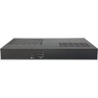
Front view of a black electronic device with ventilation grilles and ports (no visible text or symbols)Disposal Instruction (US)
For better protection of our earth, please don't throw this electronic device into municipal trash bin when discarding. To minimize pollution and ensure utmost protection of the global environment, please recycle the product. For more information about the collection and recycling of Waste Electrical and Electronic Equipment (WEEE), you are invited to visit our homepage at www.aopen.com under “Green Products”
廃棄上の指示
Instruction de Disposition (French)
Copyright of this publication belongs to AOpen Inc. AOpen reserves the right to change the content of this publication without obligation to notify any party of such changes or revisions. No part of this publication may be reproduced, transcribed, transmitted, translated into any language, stored in a retrieval system in any form or by any means electronically, mechanically, optically without the prior written permission of this company.
Disclaimer
AOpen makes no warranties or representations, either expressed or implied, with respect to the content herein and specifically disclaims any warranties, merchantability of fitness for any particular purpose.
AOpen and AOpen logos used herein are registered trademarks of AOpen Inc. All other brand names and trademarks are owned by their respective owners.
Copyright © 2017 by AOpen Inc. All rights reserved.
Safety Instructions
- Please read these safety instructions carefully.
- Please keep this User's Manual for later reference.
- Please disconnect this equipment from connector before cleaning. Don't use liquid or prayed detergent for cleaning. Use moisture sheet or cloth for cleaning.
- Make sure the equipment is connected to the power source with the correct voltage, frequency, and ampere.
- All cautions and warnings on the equipment should be noted.
- Never pour any liquid into opening; this could cause fire or electrical shock.
- Never open the equipment. For safety reason, the equipment should only be opened by qualified service personnel.
- If one of the following situations arises, get the equipment checked by service personnel:
a. Liquid has penetrated into the equipment.
b. The equipment has been exposed to moisture.
c. The equipment has not worked well or you cannot get it work according to user's manual.
d. The equipment has dropped and damaged.
e. If the equipment has obvious sign of breakage.
- Caution on use of battery: Use the battery recommended by the manufacturer or the same type of battery installed by the manufacturer. If incorrect battery is used, it may cause explosion or fire hazard. Recycle or discard used batteries according to the manufacturer's instruction or your local authority.

- Safety caution concerning laser products:
DVD-ROM/CD-RW combo drive is “Class I Laser Product” This equipment, built with DVD and/or CD disc drives using laser beam to read or write data on optical discs, is classified as “Class 1 laser product”. While the laser optical drive is reading data from or writing data to an optical disc, do not force open the disc drive door. Press the Eject button to retrieve the optical disc only after the in-use indicator goes off.
-
Ambient operation temperature: 0 \~ 40 degrees C.
-
Risk of overheating!
Do not install DES3200-xxx in a closed space.
Be sure the ventilation holes in the Digital Engine side for at least 2 inches or 5cm of space for ventilation.
To ensure that other objects do not cover the ventilation holes on DES3200-xxx.

FCC notice
This device has been tested and found to comply with the limits for a Class B digital device pursuant to Part 15 of the FCC Rules. These limits are designed to provide reasonable protection against harmful interference in a residential installation. This device generates, uses, and can radiate radio frequency energy and, if not installed and used in accordance with the instructions, may cause harmful interference to radio communications.
However, there is no guarantee that interference will not occur in a particular installation. If this device does cause harmful interference to radio or television reception, which can be determined by turning the device off and on, the user is encouraged to try to correct the interference by one or more of the following measures:
■ □Reorient or relocate the receiving antenna.
■ □ Increase the separation between the device and receiver.
■ □Connect the device into an outlet on a circuit different from that to which the receiver is connected.
■ □Consult the dealer or an experienced radio/television technician for help
Notice: Shielded cables
All connections to other computing devices must be made using shielded cables to maintain compliance with FCC regulations.
Notice: Peripheral devices
Only peripherals (input/output devices, terminals, printers, etc.) certified to comply with Class B limits may be attached to this equipment. Operation with non-certified peripherals is likely to result in interference to radio and TV reception.
Caution
Changes or modifications not expressly approved by the manufacturer could void the user's authority, which is granted by the Federal Communications Commission, to operate this computer.
Operation conditions
This device complies with Part 15 of the FCC Rules. Operation is subject to the following two conditions: (1) this device may not cause harmful interference, and (2) this device must accept any interference received, including interference that may cause undesired operation.
Notice: Canadian users
This Class B digital apparatus complies with Canadian ICES-003
Index
- Outlook ......2
- Product Specification....4
- Internal Connectors ....5
- Function introduction....6
- Packing List....9
- Chassis and Holder Dimension ....10
1. Outlook
Front IO

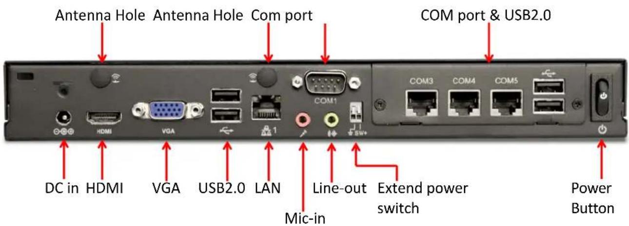
Rear IO
2. Product Specification
| CPU | Intel Bay Trail mobile Dual core CPU N2840 TDP=7.5W 2.16~2.58GHz |
| Chipset | N/A |
| Memory | Dual Channel Mode, SO-DIMM DDRIII Lx 2, 1600MHz Max memory size : 8GB |
| Graphics | Intel® HD Graphics |
| Expansion | Full Size mini Card x 1 |
| Slot | Half Size Mini Card x 1 |
| Audio | Realtek ALC269Q HD Audio CODEC on-Board. |
| LAN | Realtek RTL8111G-CG 10/100/1000Mbps LAN Controller |
| Front Panel IO | Power Button x 1 (with Power indicator (Blue)), HDD indicator (Blue) x 1, USB 2.0 Port x 2 |
| Rear Panel IO | DC 19V Jack x 1, HDMI Port x 1, VGA Port x 1, RJ45 LAN Jack x 1, USB2.0 port x 2, DB9 RS232 Serial Port x 1, HD Audio ports (speaker out x 1, Mic in x 1), RJ50 RS232 serial Port x 2, RJ50 RS232/422/485 serial port x 1 |
| Adapter | 40W (19V, 2.1A) AC Power Adapter |
| Input Voltage | AC 100 ~ 240V |
3. Internal Connectors

4. Function Introduction
4.1 Multi Serial Ports COM3, COM4, COM5
● 128 bytes transmit/receive FIFO
● compatible with 16C550/16C650/16C750 and 16C850
● Baud rate supports 115.2K, max. up to 1.5M
● Support IRQ Sharing function (IRQ3, 4, 5, 6, 7, 9, 10, 11, 12, 14, 15)
● Support HW jumper-less setting, preset with BIOS menu
● COM3 & COM4 support full function RS232
- COM5 support RS232/422/485 preset with BIOS, if BIOS setting is RS485, then also need to enabled RS485 from windows device manager
● Support RJ50 to DB9 cable accessories
● Support Windows/Linux driver
- Doesn't support S3 standby mode suspend and resume
4.2 Pin assignments of RJ50 to RS232/RS422/RS485
COM3 (RS232)

| RJ50 pin# | 2 | 4 | 6 | 8 | 9 | 3 | 5 | 7 | 10 | 1 |
| Signal | DCD | RX | TX | DTR | GND | DSR | RTS | CTS | RI | N/A |
COM4 (RS232)

| RJ50 pin# | 2 | 4 | 6 | 8 | 9 | 3 | 5 | 7 | 10 | 1 |
| Signal | DCD | RX | TX | DTR | GND | DSR | RTS | CTS | RI | N/A |
COM5 (RS232/422/485)
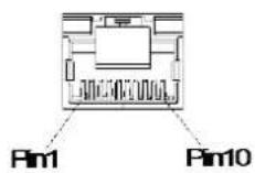
RJ50 to RS232 cable

| RJ50 Pin | RS_232 | RS_485 | RS_422 | DB9 Pin |
| 2 | DCD# | RS485_TXRX- | RS422_TX- | 1 |
| 4 | RX# | RS485_TXRX+ | RS422_TX+ | 2 |
| 6 | TX# | NC | RS422_RX+ | 3 |
| 8 | DTR# | NC | RS422_RX- | 4 |
| 9 | GND | GND | GND | 5 |
| 3 | DSR# | NC | NC | 6 |
| 5 | RTS# | NC | NC | 7 |
| 7 | CTS# | NC | NC | 8 |
| 10 | RI# | NC | NC | 9 |
| 1 | --- | NC | NC | --- |
4.3 PCIE to UART driver Windows Driver installation
☐ The driver directory named "FPCIECOM_20171003_WHQL" in driver CD
And this driver support Windows 7 32/64 Bit, Windows 10 32/64 Bit. Please don't set OS to S3 standby mode to avoid errors.
Please install MSP PCIE to UART driver follow the steps below:
- Please find the driver directory "FPCIECOM_20171003_WHQL" and double clicking the "setup.exe" based on the Administrator right.
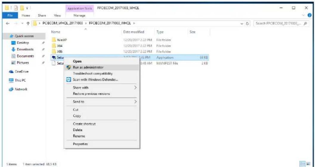
2. Double click "next" into setup wizard and it will start to install driver


- Click "Finish" when InstallShield Wizard complete installation

- Restart computer when installation success

- Availability of SHA-2 Code Signing Support for Windows 7, please install security update KB3033929 before installing PCIE to UART driver.
KB3033929 Download Link:
- X86: https://www.microsoft.com/en-us/download/details.aspx?id=46078
-
X64: https://www.microsoft.com/en-us/download/details.aspx?id=46148
-
Clink on the device manager to check the installing status. If the installing is successful, you could see "Fintek Pcie to Serial" and "Communications Port (COM)" as below figure.

4.4 COM5 setting
☐ COM5 support RS232/422/485 preset with BIOS, if BIOS setting is RS485, and then also need to enable RS485 check from windows device manager.
- BIOS setting
A. Press F2 or Delete key when system boot up to enter BIOS setup menu.
B. Select the Advanced tab from the BIOS setup screen to enter the Advanced BIOS setup screen. And you can select Multi-Serial-Port (MSP) Setting to set up the function of COM5
![S4 & SS Standby Power [Enabled] S4 & SS 900 Power [Enabled] • Multi-Serial Port (MSP) setting • CS RTC Make Settings • Miscellaneous Configuration • CDM Configuration This Setting Just available when system with HSP add-on card. +: Select Screen F1: Select Tree Enter: Select +/-: Change Opt. F1: General Help F2: Previous Values F3: Optimized Defaults F4: Save & Exit ESC: Exit Version 2.17.1249. Copyright (C) 2017 American Megatrends, Inc.](/content/2026/06/1250176/images/8933c937d9f684f38f9bed30d5c44c5960c0ea6876c15e125a943f3141c9f1e5.jpg)
C. The default setting is RS232, you can change it to RS422 or RS485
![Ratio Setup Utility - Copyright (C) 2017 American Megatrends, Inc. Advanced PCIE to UART(COMS) [RS232 F/D] PCIE to UART(COMS) — RS422 F/D RS485 H/D RS232 F/D This Setting Just available when system with HSP add-on card. If the extend card exist, this item will set FBISO4 UART3 function. F/D means that Full Duplex. H/D means that Half Duplex. +: Select Screen T1: Select Item Enter: Select +/-: Change Opt. F1: General Help F2: Previous Values F3: Optimized Defaults F4: Save & Exit E6: Exit Version 2-17.1249, Copyright (C) 2017 American Megatrends, Inc.](/content/2026/06/1250176/images/b97be99a8a627fd3f5b2d138e920a94f909257c0a553aa6ffa46eae6866791ea.jpg)
2. Setting RS485 Enable
If you had setting PCIe to UART (COM5) to RS485 in BIOS, then you also need to enable RS485 at Windows OS, please follow the step below to setup.
Clink on the device manager and then double click "Port (COM & LPT)" as below figure.
Click "Communications Port (COM5)" to setup property of COM5
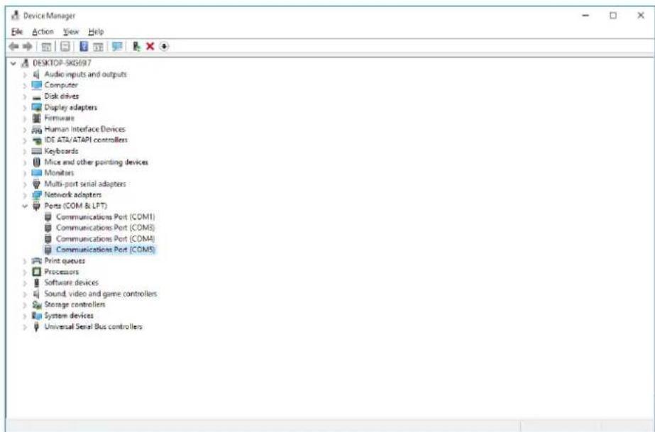
Double click "Communications Port (COM5)" and then click "Advance Setting" tab, then below window will pop up,
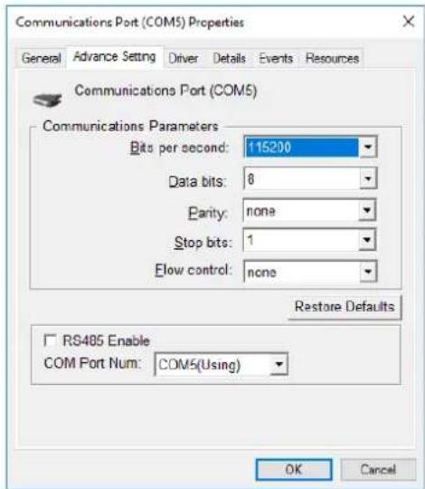
You can setup the COM port communication parameters and enable RS485 check box if BIOS also setting COM5 to RS485 function.
4.2 Extend power switch
Extend power switch at rear IO of DES3200-MSP can allow customer to extend the power switch by their demand, and customer can decide their own switch specification and cable length just follow the wire gauge and strip length.

This is a screwless type spring clamp pluggable terminal block, you can insert a wire by press the button on the terminal, please refer to the procedure below
Step 1 please prepare a pin or rod that hard enough for pushing the button on the terminal block
Step 2 push the button in the end and hold it
Step 3 insert the wire into the hole and make sure the stripped portion is fully inserted
Step 4 release the pin or rod then the wire will clamp by the terminal block
step1

natural_image
Isometric diagram of a mechanical assembly with a downward arrow and numbered label (1), no readable text or symbols present.step2

natural_image
3D diagram of a mechanical assembly with a cylindrical component inserted into a grid-like structure, labeled with number 2 (no text or symbols on the diagram itself)step3

natural_image
Diagram showing a black curved pipe inserted into a grid-like structure with a pencil inserted, no text or symbols present.step4

natural_image
Diagram of a mechanical component with a curved pipe and an upward arrow, no text or symbols present5. Packing List
1 x DES3200-MSP system
1 x User Guide
1 x Driver CD
1 x 40W Adapter and Power Cord
1 x L type Holder with 4 pcs of M3 screw
4 x M3 – stepping screws for HDD
1 x power holder
6. Chassis and Holder Dimension
A. Dimension of DES3200-xxx (unit: mm[inch])

B. LH02 L type Holder(Include 2 piece holder and 4 FPH M3 screws) Dimension of L type Holder. (unit: mm[inch])
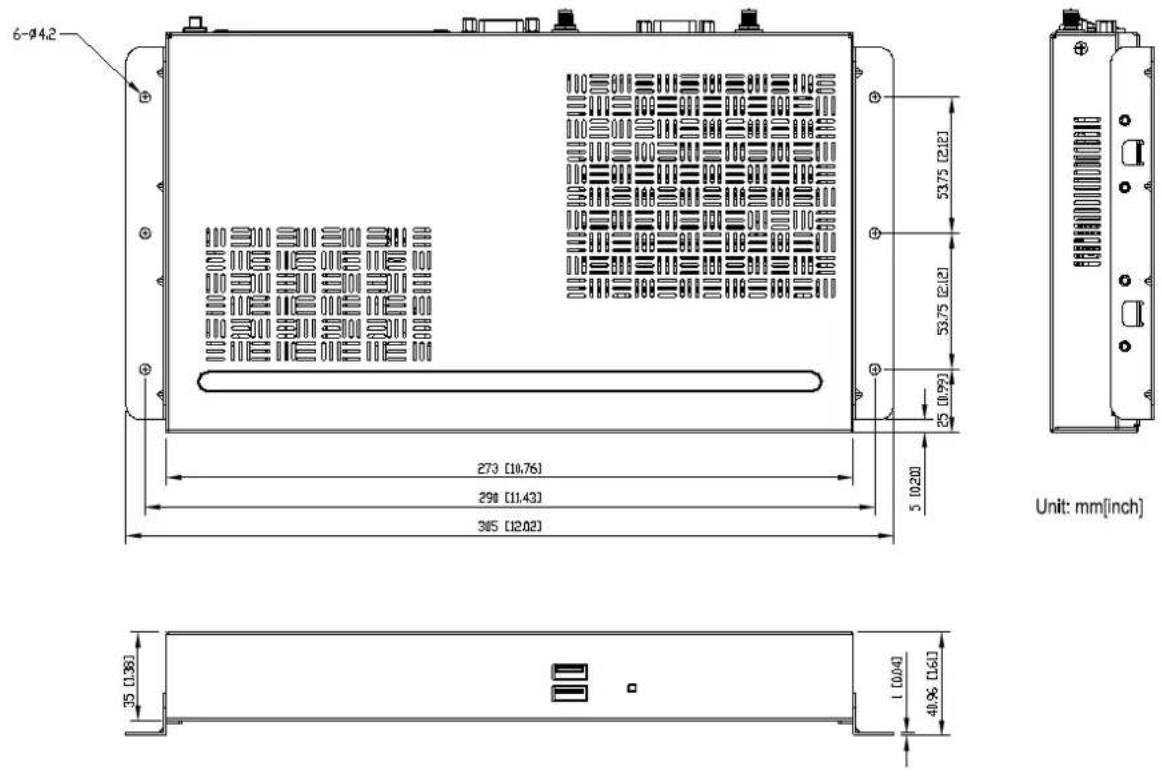
P/N : 49.DED06.0010

- Personal Computer User Guide for DES3200-MSP
- Disposal Instruction (US)
- 廃棄上の指示
- Instruction de Disposition (French)
- Disclaimer
- Safety Instructions
- FCC notice
- Notice: Shielded cables
- Notice: Peripheral devices
- Caution
- Operation conditions
- Notice: Canadian users
- Index
- Outlook
- Product Specification
- Internal Connectors
- Function Introduction
- Multi Serial Ports COM3, COM4, COM5
- Pin assignments of RJ50 to RS232/RS422/RS485
- PCIE to UART driver Windows Driver installation
- Double click "next" into setup wizard and it will start to install driver
- COM5 setting
- Setting RS485 Enable
- Extend power switch
- Packing List
- Chassis and Holder Dimension
Brand : AOPEN
Model : DES3200
Category : Computing