DNS-320LW - Server D-LINK - Free user manual and instructions
Find the device manual for free DNS-320LW D-LINK in PDF.

User questions about DNS-320LW D-LINK
0 question about this device. Answer the ones you know or ask your own.
Ask a new question about this device
Download the instructions for your Server in PDF format for free! Find your manual DNS-320LW - D-LINK and take your electronic device back in hand. On this page are published all the documents necessary for the use of your device. DNS-320LW by D-LINK.
USER MANUAL DNS-320LW D-LINK
natural_image
Black D-Link ShareCenter device with no visible text or symbols on its bodyUser Manual
ShareCenter™ 2-Bay Cloud Network Storage Enclosure
DNS-320L
Table of Contents
Product Overview 1
Before you Begin 2
System Requirements 2
Package Contents 2
Features 3
Checking the Hardware Requirements ....6
Hardware Overview 7
Front Panel 7
LED Description 8
Rear Panel (Connections) 9
Bottom Panel 10
Top Panel (Levers) 11
Getting Started 12
Hardware Setup 12
D-Link Storage Utility 15
Installation 17
Setup Wizard 17
Mapping a Drive 37
Configuration 40
Managing your DNS-320L 40
Web UI Login 41
Web UI General Layout 42
Home 42
Applications 43
Management 44
Management 45
Setup Wizard (Web UI) 45
Disk Management 49
Hard Drive Configuration 49
Hard Drive Configuration Wizard ....50
JBOD 56
RAID 0....60
RAID 1....66
Upgrade from Standard Mode to RAID 1 .....72
S.M.A.R.T. Test 78
Creating a Schedule 80
Scan Disk 81
Account Management 83
Users / Groups 83
Creating a Single User 83
Creating Multiple Users 88
Modify Users 92
Deleting Users 96
Importing Users 97
Creating a Group 100
Modifying a Group 105
Deleting a Group 110
Quotas 111
Network Shares 116
Add/Modify Network Shares Wizard ..... 117
Deleting a Network Share 124
Table of Contents
Resetting the Network Shares ...... 126
ISO Shares Setup Wizard 127
Creating an ISO Image 131
ISO image Creation Wizard 132
ISO Name and File Path Settings .... 133
ISO Tree Editing 136
Verifying the ISO image 137
Admin Password 138
Network Management 139
LAN Setup 139
IPv6 Settings 142
IPv6 Setup 143
Link Speed and LLTD Settings 145
DDNS 146
Port Forwarding.... 147
Application Management 151
FTP server 151
UPnP AV Server 155
iTunes Server 158
AFP Service 159
NFS Service 159
System Management 160
Language 160
Time and Date 161
Device 162
System Settings 163
Power Management 164
Notifications 166
Email Settings 166
SMS Settings 167
Adding an SMS Service Provider .... 168
Event Settings 169
Logs 170
Firmware Upgrade 171
USB Devices 172
UPS Settings 172
USB Storage Information 172
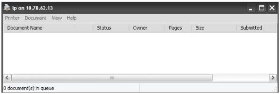
Printer Information 173
System Status 174
System Info 174
Home 176
My Photos 177
Creating an Album 178
Photo Album Wizard 179
Editing the Photo Album 183
Moving a Photo 184
Deleting the Albums 185
Sharing your Photos 186
Refresh your Photos 189
Configuring an Album 190
Sharing Photos on Google+ 193
Slideshow 196
Slideshow Toolbar 197
Cooliris 198
Photo Album - Upload from NAS 199
Photo Gallery 202
My Files 203
Upload 204
Table of Contents
Download 206
My Favorites Application.... 207
Adding Applications 208
Applications 209
FTP/HTTP Downloads 209
Remote Backups 211
Create Wizard 212
Local Backups 216
Time Machine 217
USB Backups 218
MTP Backups 219
USB Backups 219
MTP Backup Process.... 220
USB Backup Process 222
P2P Downloads 224
Settings 224
Downloads 225
My Files 226
Amazon S3 227
Creating an AWS Account 228
mydlink 233
mydlink Verification 234
mydlink Java Runtime Machine 236
Creating a New Folder 241
mydlink Settings Details 242
ShareCenter NAS Status 243
Deleting a mydlink device 244
Deleting a mydlink account 245
Knowledge Base 247
What is RAID? 247
RAID Options 249
UPS Connectivity 251
Deleting a UPS Slave 255
USB Print Server 257
Product Overview
SAFELY SHARE DIGITAL FILES LOCALLY AND OVER THE INTERNET
The D-Link DNS-320L 2-Bay Network Storage, when used with internal SATA drives ^1 , enables you to share documents, files, and digital media such as music, photos, and video with everyone on the home or office network. Remotely accessing files through the Internet is also possible with the built-in FTP server. Whether you are allowing access locally or over the Internet, keep data safe by only giving rights to specific users or groups. When configuring the DNS-320L, you can create users and groups and assign them to folders with either read, read/write or deny permissions.
This is ideal for an office environment with employee-specific sensitive data or for the home where you can ensure your children will only have access to age appropriate material. The DNS-320L will be accessible from any computer (PC, MAC, or Linux) on your network, without the need to install any software on the computer.
STREAM DIGITAL MEDIA CONTENT TO UPnP AV COMPATIBLE MEDIA PLAYERS
Back up your music, photo, and video collections to the DNS-320L for safekeeping. Then, enjoy the benefits of the built-in UPnP AV media server as you stream digital content to compatible media players ^2 (such as those found in D-Link's MediaLounge product line). This feature is highly convenient as it allows you to turn off a computer that would normally be needed for the same function.
PROTECTION, PERFORMANCE, AND FLEXIBILITY
The availability of four different hard drive modes (Standard, JBOD, RAID 0, RAID1) allows you to choose the configuration best suited to your needs. Standard mode creates two separately accessible hard drives. JBOD combines both drives in linear fashion for maximum space efficiency. RAID 0 combines both drives in a 'striped' configuration, which provides the highest performance when using a Gigabit Ethernet connection. RAID 1 causes the drives to mirror each other, providing maximum protection. If one drive fails while configured as RAID 1, the unaffected drive continues to function as a single drive until the failed drive is replaced. The new drive will then be re-mirrored, allowing the DNS-320L to return to its full protection.
To further enhance your ShareCenter's capabilities, the DNS-320L supports a proprietary mydlink service, provided to D-Link customers only, serves as a portal to those users who wish to access their data from any location. Mydlink service supports list, download, upload or delete files/folders and can see the status of a ShareCenter from any location via web browser.
Before you Begin
- Check box contents
- Check system requirements
- Ensure that you have the hardware you need for your ShareCenter device
System Requirements
For best results, the following minimum requirements are recommended on any system used to configure and use the ShareCenter:
- Computer with: 1Ghz processor / 512MB RAM / 200MB available space / CD-ROM drive
- Internet Explorer® version 7, Mozilla® Firefox® 3, Google® Chrome 3, or Apple® Safari® 4 and above
- Windows® XP (with Service Pack 2), Windows Vista®, Windows® 7
• Mac OS® X 10.5.6 or greater
• 3.5" SATA Hard Drive(s)
Package Contents
• D-Link ShareCenter® DNS-320L
• CD-ROM with Manual and Software
- Quick Installation Guide
• 12VDC 3A Output Power Adapter
• CAT5E Ethernet Cable

natural_image
Black ShareCenter brand electronic device with no visible text or symbols on its bodyFeatures
The ShareCenter® DNS-320L is an easy to install data storage platform used for remote access through a local network or from the Internet. This ShareCenter® supports up to 2 SATA hard drives and includes the product features listed below:
Equipped one 10/100/1000 Mbps auto-MDIX Gigabit Ethernet LAN port, 1000BASE-T support Half duplex and Full duplex mode
■ Embedded two SATA II 3.5" HDD interface, support 3TB HDD
2-bay Serial ATA with RAID 0/1 and JBoD supported
Equipped Ultra Cooler (Plastic housing + FAN speed control)
Support Green Ethernet
Support Smart FAN
■ Support Real time clock (RTC)
Network Options
• DHCP Client or Static IP
- NTP Server
• Windows 7/ Vista x32/64 PnP-X/ LLTD
- Dynamic DNS
• Bonjour
• UPnP Port Forwarding
• IPv6*
Network File Services
• Supports Windows XP/ Vista/ 7, Mac OSX 10.5+, Linux clients
• CIFS/SMB for Windows and Mac OS X
• NFSv3 for Linux and UNIX
• AFP3.3 for Mac OS X
- HTTP and HTTP/S for web browsers
File System
- EXT4 for internal HDD
• FAT32, NTFS for USB external Storage
File System Management
• Unicode Support for both Samba and FTP server
- File sharing: Windows/ Mac/ Linux
FTP server
- FTP over explicit SSL/ TLS mode (FTPES)
- FTP bandwidth and connection control
- FTP support FXP
• IP Blocking
Download Management
- HTTP/FTP schedule download
- Peer to peer (P2P) downloader
Disk Management
• RAID: Standard, JBOD, 0,1
- Raid 1 Auto/manual Rebuild
• RAID migration: Normal to RAID 1
• Disk Status Monitoring (S.M.A.R.T.)
• HDD S.M.A.R.T test
- Scandisk
• Support Advanced Format HDD
Power Management
• Power Saving (Disk idle spin-down)
- Schedule power on/off
• Auto Power Recovery
- Smart Fan Control
Folder Management
Section 1 - Product Overview
- Share Folder Level Permission
- Public Folder
• Supports ISO Mount
Remote File Sharing
• Web File Server (My Files)
- Allows user(s) to access files on the NAS using a web browser.
- FTP Server
- WebDAV
- Smart phone access
- Search and login to the NAS
- List, download, upload, rename or delete files from a NAS
- Play music, video, documents
- Photo slideshow with background music playing support
• Support mydlink portal
- Users can list, download, upload or delete files/folders from a NAS
- Users can see the status of a NAS.
User/Group Management
- User/group assignment for Network sharing and FTP server
- Quota for user and group
- Users can assign to multiple Groups
- Batch User Creation/ Import Users
Backup Management
- Schedule Backup from PC to NAS (D-Link ShareCenter Sync)
• Apple Time Machine support - Local Backup
• USB Backups (External storage and digital camera) - Remote network backup (Rsync, Remote Snapshot)
• Cloud Backup (Amazon S3)
- USB Copy Button
System Management
• Support mydlink portal
• Support D-Link Storage Utility
- OS support: Windows XP, Vista, 7, and Mac OS X
- Two access modes supported: Open mode and Account mode,
• Support Configuration file save/load - System status
- Email/ SMS notifications
• Network Recycle bin
• System/FTP Log (Syslog Client)
• Resource Monitor
USB port support:
- External Storage device
Print server
- UPS monitoring
• MTP/PTP
Media Streaming
- UPnP AV server:
• Supports PS3/Xbox 360
• Supports UPnP AV file > 4 GB
• Complies with DLNA HNv1.5
• D-Link new Media Player (including Boxee) compatible
- iTunes Server
-
My Photos
-
Create albums and manage photos
- Share photos through social networks (Google+ & Cooliris)
- Slideshows
Table of Contents
■ Supports Multilingual GUI
Web Browsers Supported
- Internet Explorer 7+
- Mozilla Firefox 3+
- Apple Safari 4+
- Google Chrome3+
• Opera 10+
Checking the Hardware Requirements
To use your DNS-320L, you will need at least one hard drive. If you plan to use RAID 1, which protects your data against one hard drive failure, you will need two hard drives.
This section will help you:
- Select the hard drives
• Determine hard disk space you will need - Ensure your data is protected
- Understand the basic requirements for a router or switch
Selecting Hard Drives:
You can use hard drives from any manufacturer and with any capacity with your DNS-320L. The D-Link ShareCenter supports standard 3.5" internal SATA drives. If you are unsure, ask your administrator or hard drive retailer/manufacturer to verify that your hard drives meet this standard
*Warning - Any pre-existing data on the drives will be erased during installation.
Determining How Much Hard Drive Space you Need:
In order to protect your data from hard drive failure, your DNS-320L requires more space than what you will use for your data, sometimes more than double the amount of space required.
Using a Router or Switch:
If you are connecting your ShareCenter to a router or switch, your router or switch needs to support Gigabit Ethernet (1000Mbit/s) for maximum performance. The ShareCenter will auto-negotiate the highest connection speed available to your router or switch. If you are using Port Bonding, use a managed switch.
Using an Uninterrupted Power Supply (UPS):
We highly recommend that you use your ShareCenter in conjunction with an uninterrupted power supply (UPS), which will protect against sudden loss in power and power surges.
Hardware Overview
Front Panel

text_image
Top Panel Front Panel USB Button Power Button ShareCenter Left HDD/ Right HDD LED IndicatorsCOMPONENTDESCRIPTION
| Top Panel | This panel unlatches simply by pressing the lever at the back. Unhook and lift up to insert or remove your hard drive(s). |
| Front Panel The casing of the entire NAS | |
| Power Button Press once to power on the ShareCenter. Press and hold the button to power it down. | |
| USB Button Press once to activate USB or press and hold to release USB activity. | |
| Left HDD/Right HDD | Indicates the position of the drive (Left or Right) |
| LED Indicators Illuminates blue or red depending on activity (see the next page for details) | |
Section 1 - Product Overview
text_image
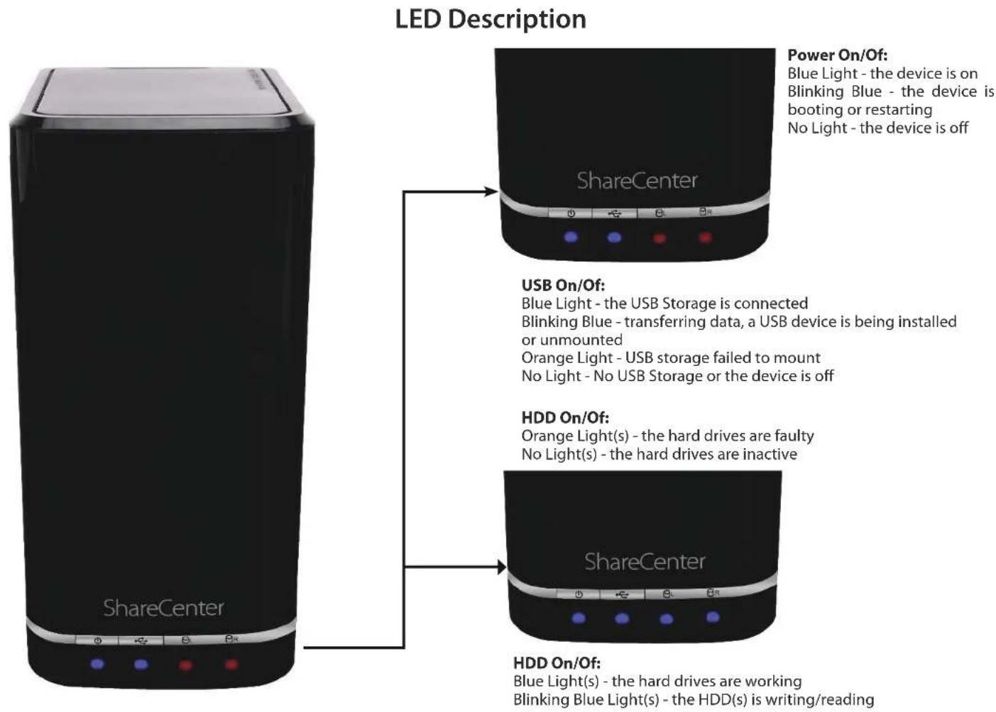
LED Description Power On/Off: Blue Light - the device is on Blinking Blue - the device is booting or restarting No Light - the device is off ShareCenter USB On/Off: Blue Light - the USB Storage is connected Blinking Blue - transferring data, a USB device is being installed or unmounted Orange Light - USB storage failed to mount No Light - No USB Storage or the device is off HDD On/Off: Orange Light(s) - the hard drives are faulty No Light(s) - the hard drives are inactive ShareCenter HDD On/Off: Blue Light(s) - the hard drives are working Blinking Blue Light(s) - the HDD(s) is writing/readingRear Panel (Connections)
text_image
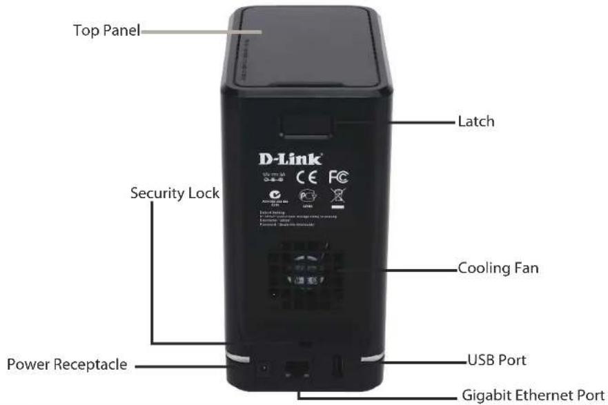
Top Panel Latch Security Lock Cooling Fan Power Receptacle USB Port Gigabit Ethernet Port| COMPONENTDESCRIPTION | |
| Cooling Fan | The cooling fan is used to cool the hard drives and features speed control. When the unit is first powered on, the fans rotate at a low speed and later rotate at a high speed when the temperature rises above 49 °C. |
| Gigabit Ethernet Ports | Use the Gigabit Ethernet port to connect the ShareCenter to the local network. The port is equipped with 2 LEDs. LED on the right will illuminate solid green for a good connection and will blink during data transmission. If this LED is off, check the connection/cable to the device you are connecting to. The LED on the left will light solid for a Gigabit connection and will remain off when connected to a 10/100 device. |
| Power Receptacle | Connect the supplied power cord to the receptacle. |
| USB Port | A single USB 2.0 (Type A) connector. The USB Host port is for Print Servers, USB memory disks, or USB UPS monitoring. |
| Latch Press the latch to release the Top Panel and insert or remove the hard drives | |
| Security Lock Prevent theft by tying a lock to the ShareCenter NAS and a desk | |
Section 1 - Product Overview
text_image
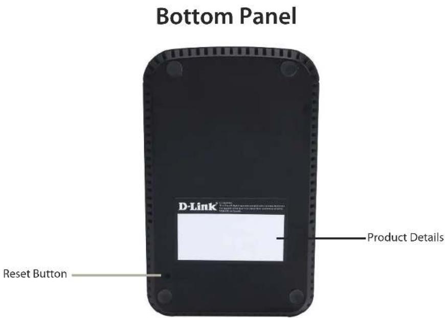
Bottom Panel D-Link® Reset Button Product DetailsCOMPONENTDESCRIPTION
Product Details Information about the product - DNS-320L. Serial Number, Part Number, Manufacturer Number
Reset Button Press and hold this button for more than 5 seconds to reset the unit to factory defaults.
Top Panel (Levers)

natural_image
Hand inserting a D-Link device into a black D-Link container (no visible text or symbols on the device itself)Pull the handles to disconnect the hard drive(s) from the SATA sockets.
Note: Remove the top cover before releasing the latches.
Getting Started Hardware Setup
This User Guide will help you get your ShareCenter set up in just a few steps. To install the ShareCenter on your local network, refer to the steps below, or skip to page 16 to run the setup wizard which will show you how to install and configure your DNS-320L.

natural_image
Hand pointing at a black industrial device with a label on its side (no visible text or symbols on the device body)Step 1 - Remove the top panel by firmly pressing the latch at the back.

natural_image
Hand placing a black electronic device into a black case with red buttons (no visible text or symbols)Step 2 - Once the faceplate is unlatched, pull it off the device to expose the devices's bays.
Note: Make sure to align the drive connector to the SATA connector at the back edge inside the drive bay of the ShareCenter. Gently push the drive in until it connects. When a drive is inserted properly, you will feel it "set" into the connector. Some hard drives that are thin or oddly shaped may need to be inserted carefully into position. If a drive is not properly set in place, the hard drive LED will not illuminate after powering on the device.
Section 2 - Getting Started
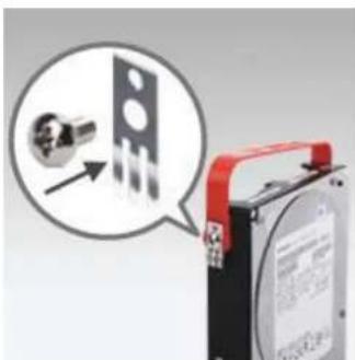
natural_image
Close-up of a battery pack with a close-up inset showing a mechanical component (no visible text or symbols)Step 3 - Attach the hard drive brackets to the sides of your hard drives with the included screws. Ensure the brackets are aligned so that when the hard drive is inserted, the arrow on the bracket points to the front of the ShareCenter.
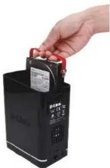
natural_image
Hand placing a small electronic component into a black battery (no visible text or symbols)Step 4 - Insert up to two 3.5" SATA hard drives into the drive bays.
Section 2 - Getting Started
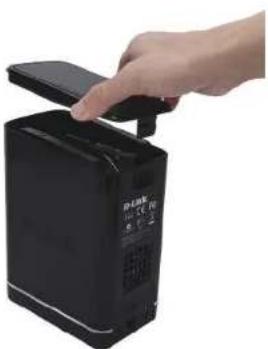
natural_image
Hand placing a small electronic device into a black device (no visible text or symbols)Step 5 - Re-attach the top panel. Ensure the latch is inserted inside the panel.

text_image
D-Link D-Link CE PCStep 7 - Connect the power adapter to the power receptacle.

text_image
D-Link D-Link CE FC 0.0 0.0 0.0 0.0 0.0 0.0 0.0 0.0 0.0 0.0 0.0 0.0 0.0 0.0 0.0 0.0 0.0 0.0 0.0 0.0 0.0 0.0 0.0 0.0 0.0 0.0 0.1 0.1 0.1 0.1 0.1 0.1 0.1 0.1 0.1 0.1 0.1 0.1 0.1 0.1 0.1 0.1 0.1 0.1 0.1 0.1 0.1 0.1 0.1 0.1 0.1 0.1 0.2 0.2 0.2 0.2 0.2 0.2 0.2 0.2 0.2 0.2 0.2 0.2 0.2 0.2 0.2 0.2 0.2 0.2 0.2 0.2 0.2 0.2 0.2 0.2 0.2 0.2 0.3 0.3 0.3 0.3 0.3 0.3 0.3 0.3 0.3 0.3 0.3 0.3 0.3 0.3 0.3 0.3 0.3 0.3 0.3 0.3 0.3 0.3 0.3 0.3 0.3 0.3 0.4 0.4 0.4 0.4 0.4 0.4 0.4 0.4 0.4 0.4 0.4 0.4 0.4 0.4 0.4 0.4 0.4 0.4 0.4 0.4 0.4 0.4 0.4 0.4 0.5 0.5 0.5 0.5 0.5 0.5 0.5 0.5 0.5 0.5 0.5 0.5 0.5 0.5 0.5 0.5 0.5 0.5 0.5 0.5 0.6 0.6 0.6 0.6 0.6 0.6 0.6 0.6 0.6 0.6 0.6 0.6 0.6 0.6 0.6 0.6 0.6 0.6 0.7 0.7 0.7 0.7 0.7 0.7 0.7 0.7 0.7 0.7 0.7 0.7 0.7 0.7 0.7 0.7 1Step 6 - Connect an Ethernet cable to the Ethernet port. This cable should connect the ShareCenter to your local network via a router, switch, or directly to a computer for configuration (cross-over cable required).
D-Link Storage Utility
When first powered on, during the initial boot sequence, the ShareCenter will wait to be assigned an IP address via DHCP. If it does not receive a DHCP assigned IP address, the ShareCenter will be automatically assigned a 169.254.xxx.xxx address. It is recommended that you use the included D-Link Storage Utility software when accessing and configuring the ShareCenter for the first time. If you want to change the IP address before logging in or you are having trouble connecting to the ShareCenter IP address, you can use the Storage Utility software included on the product CD to locate the device on your network and make any necessary changes.
Network Storage The D-Link Storage Utility displays any ShareCenter Device: devices it detects on the network here.
Refresh: Click Refresh to refresh the device list.
Configuration: Click Configuration to access the Web based configuration of the ShareCenter.
LAN: Configure the LAN Settings for the ShareCenter here.
Apply: Click Apply to save changes to the LAN Settings.
Drive Mapping: Volumes available for mapping are displayed here.
Available Drive Choose an available drive letter. Click Connect to map Letters: the selected volume. Click Disconnect to disconnect the selected mapped volume.
About: Click About to view the software version of the Easy Search Utility.
Exit: Click Exit to close the utility.

text_image
D-Link Storage Utility Network Storage Device Name P Netmask dlink-320L 192.168.0.102 255.255.255.0 LAN LAN1 IP: 192 168 0 102 Netmask: 255 255 255 0 Gateway: 192 168 0 1 Receive DHCP: Enable Apply Drive Mapping Volume Name Location Volume_1 Available Drive Letters: Z Connect Disconnect About ExitSection 2 - Getting Started
Select the ShareCenter from the list and click the Configuration button. This will launch the computer's default web browser and direct it to the IP address listed for the device. Make sure the browser is not configured to use a proxy server.
Note: The computer used to access the ShareCenter web-based configuration manager must be on the same subnet as the ShareCenter. If your network is using a DHCP server and the computer receives IP settings from DHCP server, the ShareCenter will automatically be in the same subnet.

text_image
D-Link Storage Utility Network Storage Device Name IP Netmask dlink-320L 192.168.0.102 255.255.255.0 LAN LAN1 IP: 192 . 168 . 0 . 102 Netmask: 255 . 255 . 255 . 0 Gateway: 192 . 168 . 0 . 1 Receive DHCP : Enable Apply Drive Mapping Volume Name Location Volume_1 Available Drive Letters : Z: Connect Disconnect About ExitInstallation Setup Wizard
To run the Setup Wizard, insert the ShareCenter CD into your CD-ROM drive.
Step 1 - When the autorun screen appears, click Install
Note: Windows Firewall presents you with a warning message to unblock the device. Click Unblock to give your computer access to the NAS.
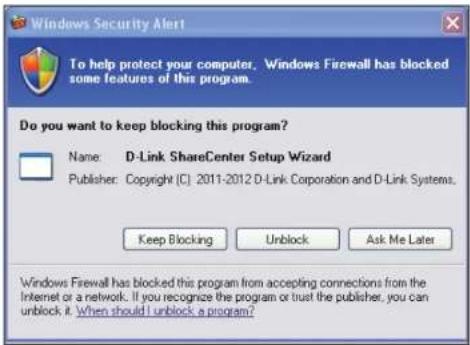
text_image
Windows Security Alert To help protect your computer. Windows Firewall has blocked some features of this program. Do you want to keep blocking this program? Name: D-Link ShareCenter Setup Wizard Publisher: Copyright (C) 2011-2012 D-Link Corporation and D-Link Systems. Keep Blocking Unlock Ask Me Later Windows Firewall has blocked this program from accepting connections from the Internet or a network. If you recognize the program or trust the publisher, you can unlock it. When should I unlock a program?Step 2 - Select the Language of your choice and then click the Start button.

natural_image
Black rectangular device labeled 'Shawn Center' (no additional text or symbols visible)Install the Hard Drives
Step 3 - Follow the instructions to remove the top cover of your ShareCenter.
Click Next to continue.
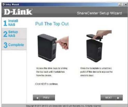
text_image
D-Link ShareCenter Setup Wizard 1 Install NAS 2 Setup NAS 3 Complete Pull The Top Out Access the drive bays by sliding the top back until it untatches from the device. Once the receptacle is untatched, pull it off the device to expose the device's bays. Click NEXT to continue FILEV NEXT Copyright © 2011-2012 D-Link Corporation and D-Link Systems, Inc. All rights reserved.Step 4 - Attach the Hard Drives Bracket(s) to the side of the hard drives as indicated.
Click Next to continue.
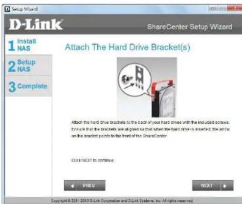
text_image
Setup Wizard D-Link ShareCenter Setup Wizard 1 Install NAS 2 Setup NAS 3 Complete Attach The Hard Drive Bracket(s) Attach the hard drive brackets to the back of your hard driven with the included screws. Ensure that the brackets are designed so that when the hard drive is inserted, the arrow on the bracket points to the front of the ShareCenter. Click NEXT to continue. PREV NEXT Copyright © 2019 D-Link Corporation and D-Link Systems, Inc. All rights reserved.Section 3 - Installation
Step 5 - Slide one, or two hard drive into an available hard drive bay of your ShareCenter.
Click Next to continue.

text_image
Setup Wizard D-Link ShareCenter Setup Wizard 1 Install NAS 2 Setup NAS 3 Complete Install The Hard Drive(s) Align the drives with the grooves in the enclosure, insert one or two 3.5" SATA hard drives into the drive bays until they are firmly sealed. If a drive has been inserted incomably, the LED will not right-up. Click NEXT to continue... PFEV NEXT Copyright © 2011 2013 D Link Corporation and D Link Systems, Inc. All rights reserved.Connect to your Network
Step 6 - With the hard drives installed properly into each bay, close the chassis by re-attaching the top panel into place.
Click Next to continue.
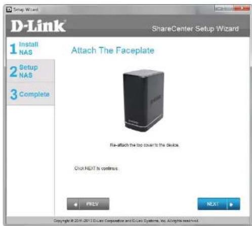
text_image
Setup Wizard D-Link® ShareCenter Setup Wizard 1 Install NAS 2 Setup NAS 3 Complete Attach The Faceplate Ris-attach the top cover to the device. Click NEXT is continue. PREV NEXT Copyright © 2019-2019 D-Link Corporation and D-Link Systems, Inc. All rights reserved.Step 7 - Connect a CAT5 Ethernet cable to your ShareCenter and connect the other end to a switch or router (Local LAN).
Click Next to continue.

text_image
D-Link® ShareCenter Setup Wizard 1 Install NAS 2 Setup NAS 3 Complete Connect To Your Network Connect an Ethernet cable to the Ethernet port of your DVB-320L. This cable should connect your DVB-320L to your local network via a router or switch, or directly to a computer for configuration. Click NEXT to continue. PREV NEXT Copyright © 2019-2019 D-Link Corporation and D-Link Systems, Inc. All rights reserved.Power and Device Selection
Step 8 - Connect the power adapter connector to the power receptacle on the back of the ShareCenter. Then, power on the ShareCenter by pressing the power button located in the front panel.
Click Next to continue.
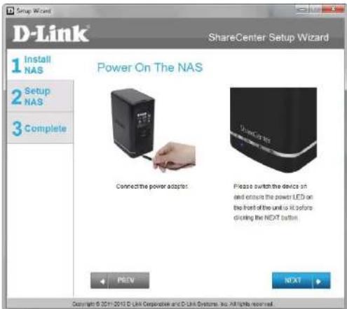
text_image
D-Link ShareCenter Setup Wizard 1 Install NAS 2 Setup NAS 3 Complete Power On The NAS Connect the power adapter. Please switch the device sh and ensure the power LED on the front of the unit is it before clicking the NEXT button. Copyright © 2013 D-Link Corporate and D-Link Systems, Inc. All rights reserved.Step 9 - With the power on, press the Next button on the device and check and make sure the IP address of your ShareCenter matches what you see on the screen.
Note: Allow 1-2 minutes for the DNS-320L to be recognized.
Click Next to continue.
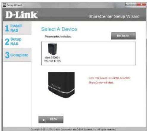
text_image
D-Link ShareCenter Setup Wizard 1 Install NAS 2 Setup NAS 3 Complete Select A Device Please select a device: REFRESH drink 000001 192.168.0.195 Note: the power LED drives selected ShowCenter will block. + PREV Copyright © 2011-2015 Unit Corporation and D-Unit Systems, Inc. All rights reserved.Admin Password
Step 10 - Enter the administrator password. If this is the first time you are doing the installation on this NAS, leave the password blank.
Click Next to continue.

text_image
D-Link ShareCenter Setup Wizard 1 Install NAS 2 Setup NAS 3 Complete Input The Admin Password Enter your administrator account password in order to login to your NAS. For the first install, the password should be blank, but also the username should be "admin". Username: admin Password: PREV NEXT Copyright © 2011-2013 D4Link Composites and D4Link Systems, Inc. All rights reserved.Step 11 - In this step you can create a new password for the Admin username. It is recommended you set a password, however you may also leave the fields blank.
Click Next to continue.

text_image
D-Link 1 Install NAS 2 Setup NAS 3 Complete Create A New Password For Your NAS Create a new password to secure your NAS. You will need to use admin as the username and the new password, you have created whenever you login to the GUI of your ShareCenter. Admin ID: admin Password: Confirm Password: Note: Password must contain at least 5-10 characters. PREV NEXT Copyright © 2014/2015 Dubai Corporation and Dubai Systems, Inc. All rights reserved.Networking Setup
Step 12 - You may either use Static IP or DHCP to configure the IP network settings of the ShareCenter. If you select Static IP, then enter the IP parameters as listed.
Click Next to continue.

text_image
D-Link ShareCenter Setup Wizard 1 Install NAS 2 Setup NAS 3 Complete Configure Device LAN If you want to set on IP address for your ShareCenter please select "Static IP" and enter the required information. Otherwise click NEXT. IP Address: 192.560.0.105 Subset Mask: 255.260.265.0 Gateway: 192.560.0.1 DNS1: DNS2: 172.19.10.100 PREV NEXT Copyright © 2011-2013 D-Link Connection and O-Link Systems, Inc. All rights reserved.Device Information and Dynamic DNS
Step 13 - If you want your ShareCenter to be part of a Windows Workgroup network, enter the workgroup name, a name for the device, and a description. The name you entered will be used whenever you map one of the ShareCenter volumes as a Network Drive.
Click Next to continue.
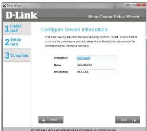
text_image
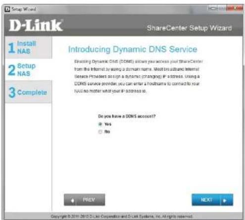
D-Link ShareCenter Setup Wizard 1 Install NAS 2 Setup NAS 3 Complete Configure Device Information If you have a w/m group other than your Operating System's default, or if you want to customize the device name and description of your ShareCenter, please enter the information below. Otherwise click NEXT. Workgroup: www.dlink Name: disk.000001 Descriptions: DNS.320L PREV NEXT Copyright © 2019 2019 D-Link Corporation and D-Link Systems, Inc. All rights reserved.Step 14 - Click the Yes radio button if you already have a DDNS account to use for the ShareCenter DDNS. Click the No radio button and proceed to step 15 to obtain a new DDNS account.
Click Next to continue.
text_image
D-Link 1 Install NAS 2 Setup NAS 3 Complete ShareCenter Setup Wizard Introducing Dynamic DNS Service Enabling Dynamic DNS (DDNS) allows you access your ShareCenter from the Internet by using a domain name. Most other Internet Service Providers assign a dynamic (changing) if a stress. Using a DDNS service provider, you can enter a hostname to connect to your NAS no matter what your IP address is. Do you have a DDNS account? Yes No PREV NEXT Copyright © 2011 2013 D-Link Corporation and D-Link Systems, Inc. All rights reserved.Dynamic DNS Account Setup
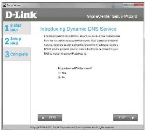
Step 15 - Enter the DDNS parameters requested in this window so that your ShareCenter can be accessed by a URL over the Internet.
Click Next to continue.
text_image
D-Link ShareCenter Setup Wizard 1 Install NAS 2 Setup NAS 3 Complete Introducing Dynamic DNS Service Enabling Dynamic DNS (DINCS) allows you access your ShareCenter from the Internet by using a domain name. Most broadcasted Internet Service Providers assign a dynamic (changing) IP address. Using a DOPNS service provider, you can enter a hostname to connect to your NAS no matter what your IP address is. Do you have a DOSS account? Yes No PREV BEAT Copyright © 2011-2013 Digital Corporation and D-Link Systems, no rights reserved.Step 16 - Click Yes to go to a Wizard with instructions and links on how to obtain a free DDNS account.
Click No skips the DDNS account setup wizard and transfers you back to the ShareCenter Setup Wizard.

text_image
Do you want to apply a DDNS account now? Yes NoDDNS Account and System Time
Step 17 - Follow the steps listed here in order to create a DDNS account and configure your LAN equipment and ShareCenter to work with the new settings.
Click Close to continue.

text_image
How to apply and configure a DDNS account 1. Sign up for D-Link's Free DDNS service at www.DJuniDDNS.com 2. Create an account You first need to create an account. After entering your user information, you will be sent an e-mail to verify your e-mail address and confirm your account. You can then log in. You can also use this username and password at www.djuni.com. 3. Create a hostname After your account is confirmed, again. Click the add host time, fill in a best, and then click "Slave" If you create a DNS query for the hostname, you will get the IP address back that you entered. 4. Configure your NAS To make sure that your hostname always matches your IP address as it changes, your NAS has an update client that meets your IP address and will update the hostname should the IP address change. Enter your username, password, and hostname. Select an appropriate DDNS server from the list. Your NAS should start updating. 5. Configure your Router To enable this function, part number 80 needs to be opened to the NAS from your local router's setup. CloseStep 18 - Select your time zone and then set the time and date. You can set the time and date manually, from an NTP server, or from your computer.
Click Next to continue.

text_image
D-Link® ShareCenter Setup Wizard 1 Install NAS 2 Setup NAS 3 Complete Configure System Time Configure Time Zone, NTP server, system Date and Time Time Zone: UAM!~#1.08 Brussels, Copenhagen, Oslo 0, Paris Enable NTP Server: NTP Server: << Select NTP Server Data and Time: Monday , November 29, 1999 Hour 21 Minute 24 Second 57 Set Time from my computer PREV NEXT Copyright © 2011-2012 D-Link Corporation and D-Link Systems, Inc. All rights reservedEmail Settings and Volume Information
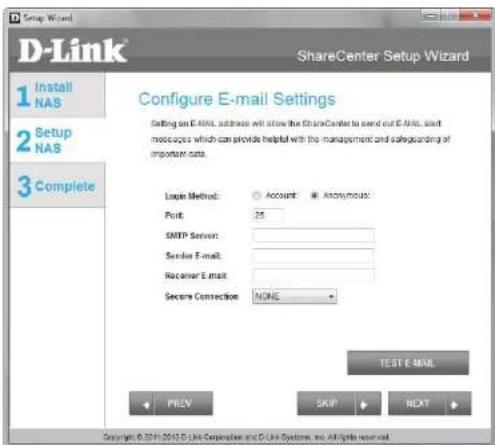
Step 19 - You can configure messages to be sent alerting you to certain operational conditions and drive status conditions to your e-mail account. These alerts can prove helpful with the management and safeguarding of important data.
Enter your e-mail information and settings and then click Next to continue. If you do not want to configure your e-mail settings, click Skip to continue.
text_image
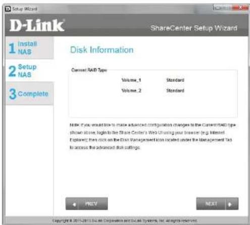
D-Link ShareCenter Setup Wizard 1 Install NAS 2 Setup NAS 3 Complete Configure E-mail Settings Setting on E-MAIL, address will allow the ShareCenter to send out E-MAIL, start messages which can provide helpful with the management and safeguarding of important data. Login Method: Account: Anonymous: Port: 25 SMTP Server: Sender E-mail: Receiver E-mail: Secure Connection: NONE TEST E-MAIL PREV SKIP NEXT Copyright © 2019 D-Link Corporation and D-Link Systems, Inc. All rights reserved.Step 20 - This step is informational and shows any currently configured Volumes previously setup on the ShareCenter®.
Click Next to continue.
text_image
D-Link ShareCenter Setup Wizard 1 Install NAS 2 Setup NAS 3 Complete Disk Information Current RAID Type Volume_1 Standard Volume_2 Standard Note: If you would how to make advanced configuration changes to the Current RAID type shown above, begin to the Share Center's Web UI using your browser (e.g. Interest). Exploring then click on the Disk Management Tool located under the Management Tool to access the advanced disk settings. PREV NEXT Copyright © 2017-2018 D-Link Corporation and D-Link Systems, Inc. rights reserved.RAID Configuration
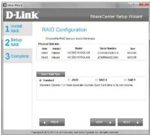
Step 21 - Select one of the volume RAID types. Clicking on each RAID type radio button will display a description.
For more information concerning the different RAID Disk Formats please refer to the Knowledge Base section in this manual.
Click Next to continue.
text_image
D-Link ShareCenter Setup Wizard 1 Install NAS 2 Setup NAS 3 Complete RAID Configuration Choose the RAID type you would like to draw. Physical Disk Info Disk 1 Disk2 Model HC5C0190CLAS8 HC5C0190CLAS8 Serial Number JCE950H002K7LA JCE950H002L38A Size 1600GB 1600GB Select Base Type Standard JDOO RAID 0 RAID 1 Standard Creates 1 or more separate volumes. Each hard drive is its own volume. PREV SKIP NEXT Copyright © 2014/2015 Cloud Corporation and Cloud System, for all rights reserved.Mapping a Drive and Checking Volume Summary
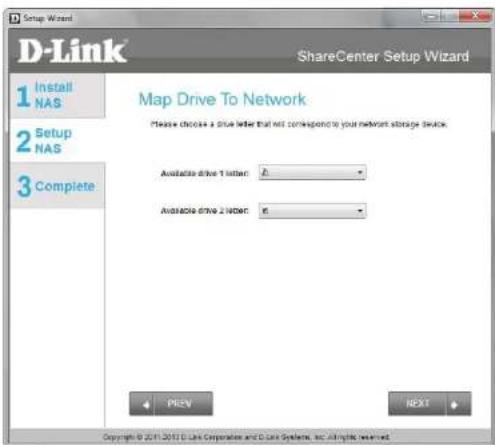
Step 22 - This step allows you to map the volume(s) created as network drive(s) on your computer.
Click Next to continue.
text_image
Setup Wizard D-Link® ShareCenter Setup Wizard 1 Install NAS 2 Setup NAS 3 Complete Map Drive To Network Please choose a drive letter that not correspond to your network storage switch. Available drive 1 letter: 0 Available drive 2 letter: 0 PREV NEXT Copyright © 2011 D Line Corporation and C Line System, etc. All rights reserved.Step 23 - Review the detailed summary of your volume configuration here before clicking next and starting the drive format. If necessary use the PREV button to go back and reconfigure the RAID configuration of the volume(s).
Click Next to continue.

text_image
D-Link ShareCenter Setup Wizard 1 Install NAS 2 Setup NAS 3 Complete Volume Configuration Summary Below is the summary of your configuration information, including the Volume Name(s), RAID Type selected, Total-Hard Drive Capacity, and the Drive Letter that will be mapped to you computer. Volume 1 - Standard Total Hard Drive Capacity 907GB Drive Letter Z DMC Disk1 Volume 2 - Standard Total Hard Drive Capacity 907GB Drive Letter Y DMC Disk2 Click NEXT to proceed to Hard Drive Formatting. + PREV NEXT Copyright © 2011 D-Link Corporation and ECUA Systems, Inc. All rights reserved.Formatting Volumes
Step 24 - When you click Next, a warning message will appear to inform you that all data on the drive(s) will be lost. Click Yes to proceed or No to exit.
Click Next to continue.

text_image
You are about to format the hard drive(s). All data will be erased. Do you wish to continue? Yes NoStep 25 - During the formatting process the wizard displays a percentage complete bar for each hard drive.
Click Next to continue.
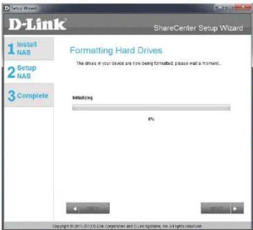
text_image
D-Link ShareCenter Setup Wizard 1 Install NAS 2 Setup NAS 3 Complete Formatting Hard Drives The drives in your devices are now being formatted, please wait a moment... Initializing 0% Copyright © 2012 D-Link Configuration and C-Link Systems, Inc. All rights reserved.Formatting Hard Drives
Step 26 - The wizard will notify you when formatting has completed successfully.
Click Next to continue.

text_image
D-Link ShareCenter Setup Wizard 1 Install NAS 2 Setup NAS 3 Complete Formatting Hard Drives The drives in your device are now being formatted, please wait a moment. Success 5% Copyright © 2011.2012 D Link Corporation and C UI Systems, Inc. All rights reserved.Step 27 - The Format is complete.
Click Next to continue.
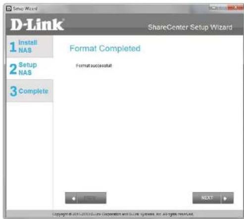
text_image
D-Link ShareCenter Setup Wizard 1 Install NAS 2 Setup NAS 3 Complete Format Completed Format successful! NEXT Copyright © 2014/2015 Install Incorporated and Guide Systems, Inc. All rights reserved.Connecting to the mydlink
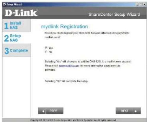
Step 28 - D-Link has provided a mydlink service that allows you to remotely access the files from your NAS through the mydlink portal. Read the installation instructions and wait for the process to complete.
Click Next to continue.
text_image
D-Link ShareCenter Setup Wizard 1 Install NAS 2 Setup NAS 3 Complete mydlink Registration Would you file to register your DNS-320L Network attached storage(DNS) to mydlink.com? C: Yes C: No Selecting "Yes" will allow you to add the DNS-320L to a mydlink.com account. Please visit www.mudlink.com for more information about services provided. Detecting "No" will complete the setup. PREV NEXT Copyright © 2011-2013 D-Link Corporation and D-Link Systems, Inc. All rights reserved.Section 3 - Installation
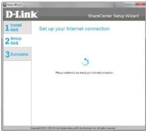
Step 29 - The wizard connects you to the mydlink servers and configures your cloud service.
Click Next to continue.
text_image
Setup Wizard D-Link ShareCenter Setup Wizard 1 Install NAS 2 Setup NAS 3 Complete Set up your Internet connection Please wait while we check your Internet connection... Copyright © 2011-2013 D-Link Co-operative and D-Link Systems, Inc. All rights reserved.Step 30 - When the wizard fails to connects you to the mydlink servers and configures your cloud service, the following screen appears to warn you of your network configuration.
Click Next to continue.

text_image
D-Link ShareCenter Setup Wizard 1 Install NAS 2 Setup NAS 3 Complete Set up your Internet connection Useable to update any disk service, please check your network configuration. Copyright © 2015-2016 D-Link Corporation and D-Link Systems, Inc. All rights reserved.Section 3 - Installation
Step 31 - The next screen allows you to setup the remote mydlink cloud service. Select the Yes radio button if you already have a mydlink account.
Enter your email address and password.
Click Next to continue.

text_image
D-Link ShareCenter Setup Wizard 1 Install NAS 2 Setup NAS 3 Complete Let's add your NAS to your mydlink account Adding your NAS to your mydlink.com account will allow you to access your NAS through the Internet. Do you have a mydlink account? Yes, I already have a mydlink account. No, I need to sign up for a new account. Please enter your mydlink sign in E-mail address and password. E-mail: Password: < > PREV < > SKIP < > BIFXT Copyright © 2014/2015 D-Link Corporation and D-Link Systems, Inc. All rights reserved.Step 32 - Alternatively, you can create a new account if you select "No, I need to sign up for a new account."
Enter your email address and a password that you can remember. Then retype the password, enter a First Name and a Last Name. Then click the checkbox that reads:
"I accept the mydlink terms and conditions."
Click Next to continue.

text_image
Setup Wizard ShareCenter Setup Wizard 1 Install NAS 2 Setup NAS 3 Complete Let's add your NAS to your mydlink account Adding your NAS to your mydlink.com account will allow you to access your NAS through the Internet. Do you have a mydlink account? Yes, I already have a mydlink account. No, I need to sign up for a new account. Please order the following information to sign up for a mydlink account! E-mail: Password: Used be allowed 6 characters and is case-sensitive. Retype passwords: First name: Last name: □ Accept the minlink terms and conditions. PREV SKIP NEXT Copyright © 2011-2012 D-Link Conservation and D-Link Systems, Inc. All rights reserved.Section 3 - Installation
Step 33 - A message appears asking you to verify your email address and account.
Click OK to continue.
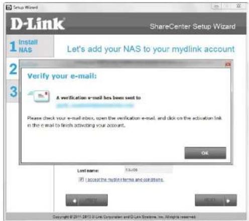
text_image
Setup Wizard D-Link ShareCenter Setup Wizard 1 Install NAS Let's add your NAS to your mydlink account 2 3 Verify your e-mail: A verification e-mail has been sent to Please check your e-mail notes, open the verification e-mail, and click on the activation link in the e-mail to finish activating your account. OK Last name: 5.3.09 ✓ Accept the mydlink norms and conditions. Copyright © 2011-2013 D-Link Corporation and D-Link Systems, Inc. All rights reserved.Wizard Complete
Step 34 - The mydlink section of the wizard installation is complete. The wizard provides you with a mydlink number. You can also tick the Add mydlink to My Favorites checkbox, or Save a shortcut to mydlink on my computer checkbox. You can use this mydlink number for future reference.
Click Finish to continue.
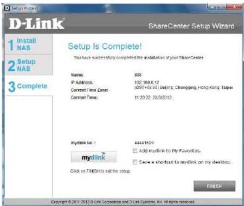
text_image
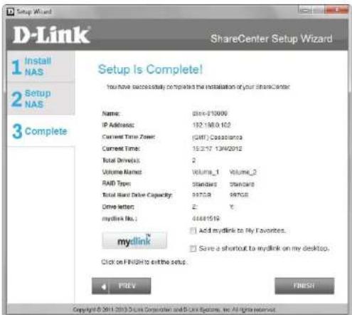
D-Link ShareCenter Setup Wizard 1 Install NAS 2 Setup NAS 3 Complete Setup Is Complete! You have successfully completed the installation of your ShareCenter Name: 988 IP Address: 102.168.0.12 Current Time Zone: (GPT+18:00) Beijing, Chongqing, Hong Kong, Taipei Current Time: 11:29:22 28/0/2012 mydlink No.: 44441520 □ Add mydlink to My Favorites. □ Save a shortcut to mydlink on my desktop. Click on FINISH to call the setup. ENGLISH Copyright © 2017-2018 Link Corporation and D-Link Systems, Inc. All rights reserved.Step 35 - The ShareCenter Setup Wizard is complete. Click Finish to exit the wizard and start using your DNS-320L.
Your ShareCenter is now installed and ready to use. If your drives are mapped using the wizard, you will be able to access them under your 'My Computer' icon.
If you did not use the wizard to map the drives, you can manually map or access the created volumes through your computers operating system. Detailed configurations using the Web UI is explained in the configuration section of this manual.
text_image
D-Link ShareCenter Setup Wizard 1 Install NAS 2 Setup NAS 3 Complete Setup Is Complete! You have successfully completed the installation of your ShareCenter Name: 0564-910000 IP Address: 182.188.162 Current Time Zone: (GIFI) C:03319703 Current Time: 15:2:17 13/4/2012 Total Drive(s): 2 Volume Name: Volume_1 Volume_2 RAID Type: Standard Standard Total Hard Drive Capacity: 9970.9 9970.9 Drive letter: 2 Y. mydlink No.: 44481519 □ Add mydlink to My Favorites. □ Save a shortcut to mydlink on my desktop. mydlink Click on FINISH to exit the setup. 4 PREV FINISH Copyright © 2011 2013 D Link Construction and D Link Systems, Inc. All rights reserved.Mapping a Drive
Map a drive to your ShareCenter using Windows ^® 7 to access it through Windows ^® Explorer.
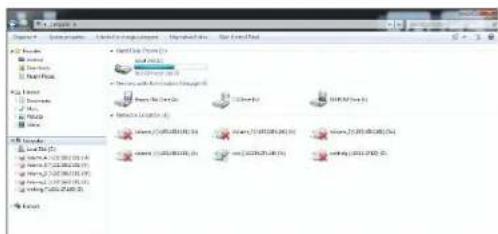
Step 1 - Click Start, then Computer (the name of your computer).
On the right-side panel is a list of your hard drives, removable storage, and network locations. If you do not have any network locations, this may be the first time you set up a network drive. Begin by clicking on 'Map network drive'.
text_image
File Edit View Insert Tools Help Share List Options Share List Options (1) Share List Options (2) Share List Options (3) Share List Options (4) Share List Options (5) Share List Options (6) Share List Options (7) Share List Options (8) Share List Options (9) Share List Options (10) Share List Options (11) Share List Options (12) Share List Options (13) Share List Options (14) Share List Options (15) Share List Options (16) Share List Options (17) Share List Options (18) Share List Options (19) Share List Options (20) Share List Options (21) Share List Options (22) Share List Options (23) Share List Options (24) Share List Options (25) Share List Options (26) Share List Options (27) Share List Options (28) Share List Options (29) Share List Options (30) Share List Options (31) Share List Options (32) Share List Options (33) Share List Options (34) Share List Options (35) Share List Options (36) Share List Options (37) Share List Options (38) Share List Options (39) Share List Options (40) Share List Options (41) Share List Options (42) Share List Options (43) Share List Options (44) Share List Options (45) Share List Options (46) Share List Options (47) Share List Options (48) Share List Options (49) Share List Options (50) Share List Options (51) Share List Options (52) Share List Options (53) Share List Options (54) Share List Options (55) Share List Options (56) Share List Options (57) Share List Options (58) Share List Options (59) Share List Options (60) Share List Options (61) Share List Options (62) Share List Options (63) Share List Options (64) Share List Options (65) Share List Options (66) Share List Options (67) Share List Options (68) Share List Options (69) Share List Options (70) Share List Options (71) Share List Options (72) Share List Options (73) Share List Options (74) Share List Options (75) Share List Options (76) Share List Options (77) Share List Options (78) Share List Options (79) Share List Options (80) Share List Options (81) Share List Options (82) Share List Options (83) Share List Options (84) Share List Options (85) Share List Options (86) Share List Options (87) Share List Options (88) Share List Options (89) Share List Options (90) Share List Options (91) Share List Options (92) Share List Options (93) Share List Options (94) Share List Options (95) Share List Options (96) Share List Options (97) Share List Options (98) Share List Options (99) Share List Options (100)Step 2 - This screen shows some details on selecting a network drive.
Click Browse to find your network.

text_image
Map Network Drive What network folder would you like to map? Specify the drive letter for the connection and the folder that you want to connect to: Drive: T1 Folder: Browse... Examples:\server/share Connect at login Connect using different credentials Connect to a Web site that you can use to store your documents and pictures Finish CancelSection 3 - Installation
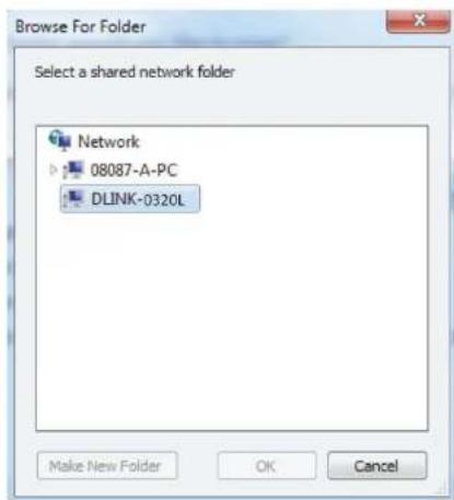
Step 3 - Windows will automatically detect all devices on your network including your ShareCenter.
text_image
Browse For Folder Select a shared network folder Network 08087-A-PC DLINK-0320L Make New Folder OK CancelStep 4 - Click on your ShareCenter to see the volumes you created earlier. Then select the volume that you wish to access and click OK.

text_image
Windows Desktop Downloads RecentPass Licms Documents Music Features Videos Computer (2) 3007-A-PC DLNC-4320L Media Devices (3) 3007-A-PC 0007-1 Other Devices (2) 3007-A-PC DLNC-4320L Formagroup Computer Local Disk (5) Formable Disk (6) Volume_59 dneprot (1:01:08-75412) Volume_1 (1:01:08-25010) (7) Volume_1 (1:01:08-0.20) (6) Volume_1 (1:01:08-0.30) (6) Volume_2 (1:01:08-0.20) (6) Volume_2 (1:01:08-0.30) (6) Volume_2 (1:01:08-0.30) (6) Network 3007-A-PC DLNC-4320LSection 3 - Installation
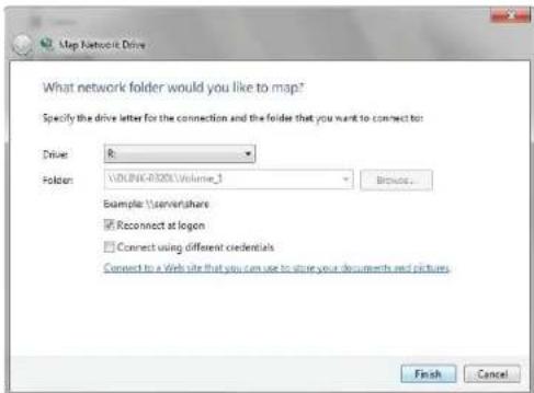
Step 5 - After selecting your volume, click Finish to proceed.
text_image
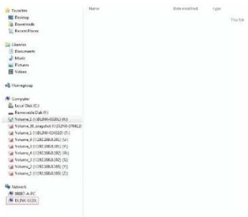
Up Network Drive What network folder would you like to map? Specify the drive letter for the connection and the folder that you want to connect to: Drive: R: Folder: \\VOUNK-0300\Volume_1 Browse... Example \server\tahres Reconnect at logon Connect using different credentials Connect to a Web site that you can use to store your documents and pictures. Finish CancelStep 6 - The drive will then appear in your Windows® Explorer under Network. This means the drive is active and ready for use.
text_image
Favorites Desktop Downloads Recent Files Libraries Documents Music Pictures Videos Homegroup Computer Local Disk (C:) Removable Disk (F:) Volume_1 (V) [DLINK-0320] (K:) Volume_30 snapshot (V) [DLINK-37045.2] Volume_1 (V) [DLINK-03451D] (T:) Volume_4 (V) [DLINK-03501] (U:) Volume_3 (V) [DLINK-03618] (V:) Volume_4 (V) [DLINK-0362] (W:) Volume_3 (V) [DLINK-0362] (G:) Volume_2 (V) [DLINK-0365] (Y:) Volume_1 (V) [DLINK-0365] (Z:) Network 98887-A-PC DLINK-0320X Name Date-matched Type This linkConfiguration Managing your DNS-320L
ShareCenter Web UI (User Interface) is a browser-based utility that allows you to manage and configure the different tools and services. The Web UI is divided into three main sections:
- Home
- Applications
- Management
| SECTIONOPTIONDESCRIPTION | ||
| Home - My Folder | My Photos | Create albums and manage photos, share photos through social networking sites, and slideshows |
| My Files | Access files on your NAS via a web browser | |
| My Favorites Application | Add the favorite applications you use on a regular basis to the Home page | |
| SECTIONOPTIONDESCRIPTION | ||
| Management Setup Wizard Step by step guide through password & time settings, connectivity, and device configuration | ||
| Disk Management Configures disk volumes, RAID, and performs disk diagnostics | ||
| Account Management Configures user and group management, network shares | ||
| Network Management Configures LAN, Dynamic DNS, and Port Forwarding | ||
| Application Management Configures FTP, UPnP, iTunes server configurations, AFP, and NFS services | ||
| System Management Configures language, time and date, device, and system settings. Also allows you to control power, notifications, view logs, do firmware upgrades, and manage USB devices. | ||
| System Status | Displays system and hard drive information along with resource monitoring | |
| SECTIONOPTIONDESCRIPTION | ||
| Applications | FTP/HTTP Downloads | Configure FTP and HTTP download settings |
| Remote Backup | Configure remote backup services | |
| Local Backups | Configures local backups, Time Machine® settings, and USB backups | |
| P2P Downloads | Configure your P2P downloads and control your download schedules | |
| My Files | Access files on your NAS via a web browser | |
| Amazon S3 | Create, modify, and delete your Amazon S3® settings |
Web UI Login
To access the Web UI, open a web browser, type in the IP address of your ShareCenter, and log in. You can find the IP address of your NAS by pressing the Next button on the front of the DNS-320L.
The following screen will appear:
Select System Administrator and enter the password created during the Setup Wizard. Click Login.

text_image
ShareCenter™ by D-Link Login Please Select Your Account: ○ System Administrator(Admin) ○ Others : Password: □ Remember Me □ SSL Login LoginNote: The computer used to access the ShareCenter web-based configuration manager must be on the same subnet as the ShareCenter. If your network is using a DHCP server and the computer receives IP settings from the DHCP, the ShareCenter® will automatically be in the same subnet.
Web UI General Layout Home
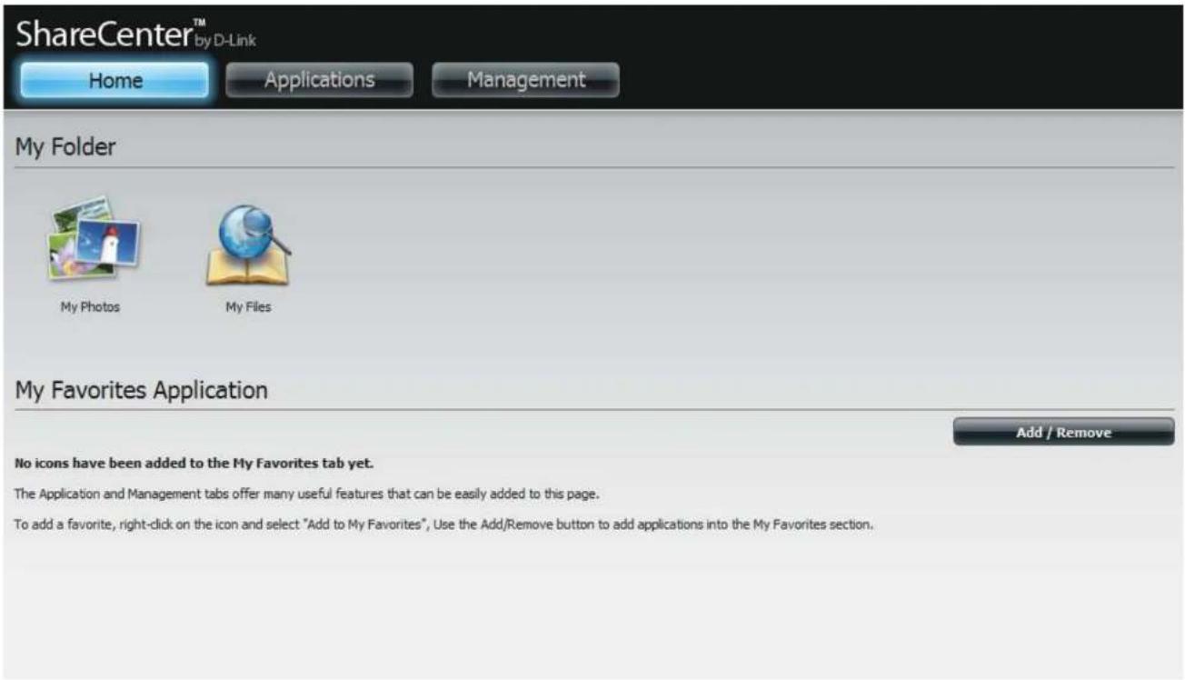
After logging in, the ShareCenter'Home' tab will appear. You will see the Applications and Management tabs alongside of it.
text_image
ShareCenter™ by D-Link Home Applications Management My Folder My Photos My Files My Favorites Application Add / Remove No icons have been added to the My Favorites tab yet. The Application and Management tabs offer many useful features that can be easily added to this page. To add a favorite, right-click on the icon and select "Add to My Favorites", Use the Add/Remove button to add applications into the My Favorites section.Applications
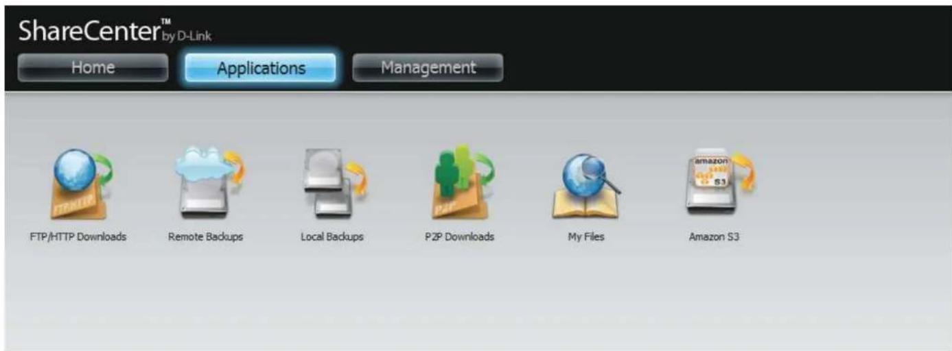
The Applications tab contains FTP/HTTP Downloads, Remote Backups, Local Backups, P2P Downloads, My Files, and Amazon S3 icons. Click on each icon to see the submenus.
text_image
ShareCenter™ by D-Link Home Applications Management FTP/HTTP Downloads Remote Backups Local Backups P2P Downloads My Files Amazon S3Management
The Management tab contains the Setup Wizard, Disk Management, Account Management, Network Management, Application Management, System Management, and Status icons. Click on each icon to see the submenus.

text_image
ShareCenter™ by D-Link Home Applications Management Setup Wizard Disk Management Account Management Network Management/Application Management System Management System StatusManagement
Setup Wizard (Web UI)
The ShareCenter has a Setup Wizard that allows you to quickly configure some of the basic device settings. Click the Setup Wizard icon to start the Setup Wizard.
Step 1 - Click the Run Wizard button to start the setup wizard.

text_image
ShareCenter My-Dark Home Applications Management Setup Wizard Wizard Settings The ShareCenter My-Dark System (Forma) enables a new support and adds business on the network for setting data and access. The setup wizard will let you adjust basic settings for your devices. Run WizardStep 2 - Click Next to continue.
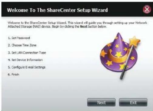
text_image
Welcome To The ShareCenter Setup Wizard Welcome to the ShareCenter Setup Wizard. This wizard will guide you through setting up your Network. Attached Storage (NAS) device. Begin by clicking the Next button below. 1. Set Password 2. Choose Time Zone 3. Set LAN Connection Type 4. Set Device Information 5. Configure E-mail Settings 6. Finish Next ExitStep 3 - Update the administrator account password here and confirm the password or leave it blank.
Click Next to continue.
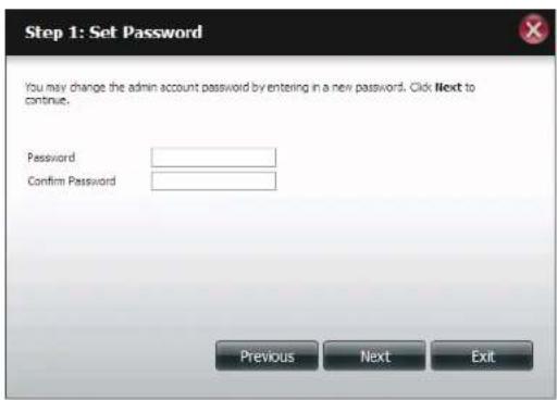
text_image
Step 1: Set Password You may change the admin account password by entering in a new password. Click Next to continue. Password Confirm Password Previous Next ExitStep 4 - Set the time zone from the drop-down menu to the appropriate geographical zone closest to your location.
Click Next to continue or click Skip to ignore these settings.
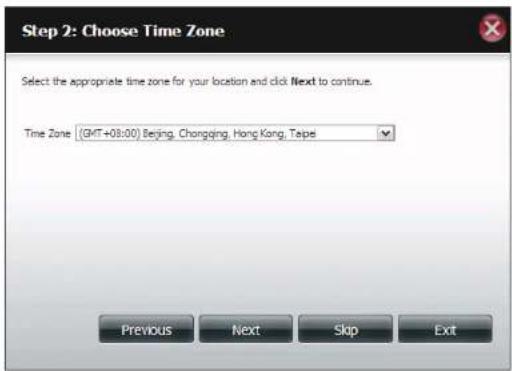
text_image
Step 2: Choose Time Zone Select the appropriate time zone for your location and click Next to continue. Time Zone | (GMT+03:00) Beijing, Changqing, Hong Kong, Taipei Previous Next Skip ExitStep 5 - Select DHCP to obtain IP settings automatically from a DHCP server (router) or Static to assign the parameters below manually.
IP Address: Enter an IP address for the DNS-320L.
Subnet Mask: Enter the subnet mask of your network.
Gateway IP Address: Enter the IP address of your gateway (usually the local IP of your router).
DNS Servers: Enter the IP address(es) of your DNS server(s). DNS1 is usually the IP address of your router.
Click Next to continue or click Skip to ignore these settings.
Step 6 - Here you can assign a workgroup and name to the ShareCenter with a short description.
Click Next to continue or click Skip to ignore these settings.

text_image
Step 3: Set LAN Connection Type Select your connection type below. If you plan to set your IP. Staticly, verify that all information in the fields is correct before proceeding. Click Next to continue. ○ DHCP Client ● Static IP IP Address 10.78.62.13 Subset Mask 255.6.0.0 Gateway IP Address 10.78.62.13 DNS1 172.16.10.100 DNS2 172.16.10.99 Previous Next Skip Exit
text_image
Step 4: Set Device Information The fields below allow your NAS device to join your Windows workgroup so that computers on your network can discover the device through the network map. The name and description field allow you to customize what your device is called on the network. Click Next to continue. Workgroup workgroup Name disk-0320L Description DNS-320L Previous Skip Next ExitSection 4 - Configuration
Step 7 - Click Account and enter your e-mail information in the boxes provided to receive Event Alerts from the ShareCenter. Click Anonymous to create a random account with no specific settings.
Click Next to continue or click Skip to ignore these settings.
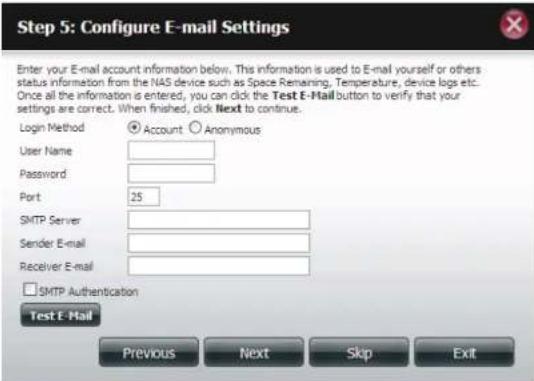
text_image
Step 5: Configure E-mail Settings Enter your E-mail account information below. This information is used to E-mail yourself or others status information from the NAS device such as Space Remaining, Temperature, device logs etc. Once all the information is entered, you can click the Test E-Mail button to verify that your settings are correct. When finished, click Next to continue. Login Method Account Anonymous User Name Password Port 25 SMTP Server Sender E-mail Receiver E-mail □ SMTP Authentication Test E-Mail Previous Next Skip ExitStep 8 - Click the Previous button to go back and check your settings. If you are satisfied with the settings, click the Finish button to save and complete the wizard. Click Exit to end the wizard without saving the settings.

text_image
Step 6: Finish The Setup Wizard is now complete. Click Previous to make any changes. If all settings are correct you may click the Finish button to save the settings on your NAS. Previous Finish ExitDisk Management
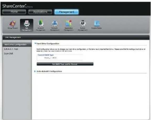
Hard Drive Configuration
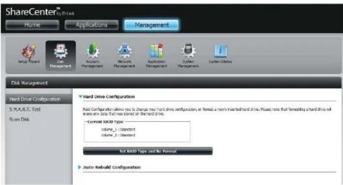
To setup the Hard Drive RAID configuration of your ShareCenter, click on the Management tab and then the Disk Management icon. Select the Hard Drive Configuration menu item on the left of the window. This menu will allow you to set the RAID type and format your hard drives.
Hard Drive Your ShareCenter hard drives can be Configuration: configured here and formatted in various RAID configurations.
Current Raid Type: If the drives are already formatted the RAID configuration will be displayed here.
Set RAID type and Click on this button to launch a wizard that Reformat: allows you to select the RAID configuration and format the drives.
Auto-Rebuild If you have chosen RAID 1 as the configuration Configuration: option, then set the Auto-Rebuild function here using the radio buttons.
Enable Auto-Rebuild: Enabling Auto-Rebuild will rebuild a failed RAID 1 drive when a new drive has replaced the degraded one.
Disable Auto-Rebuild: If you do not want to automatically rebuild drives after a failure when using the RAID 1 functionality then you can check this option.
Note: You can still rebuild a drive using the RAID 1 functionality however you must initiate the rebuild manually.
Manual Rebuild Now: If Auto-Rebuild is disabled then you can use the Manual Rebuild option by clicking this button.
text_image
ShareCenter™ by D-link Home Applications Management Setup Wizard Disk Management Account Management Network Management Application Management System Management System Status Disk Management Hard Drive Configuration 5.MAULT Test Scan Disk Hard Drive Configuration Raid Configuration allows you to change your hard drive configuration, or format a newly installed hard drive. Please note that formatting a hard drive will access any data that was stored on the hard drive. —Current RAID Type Volume_1 (Standard) Volume_2 (Standard) Set RAID Type and No Format Auto Rebuild ConfigurationManually Rebuild Now
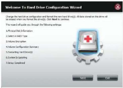
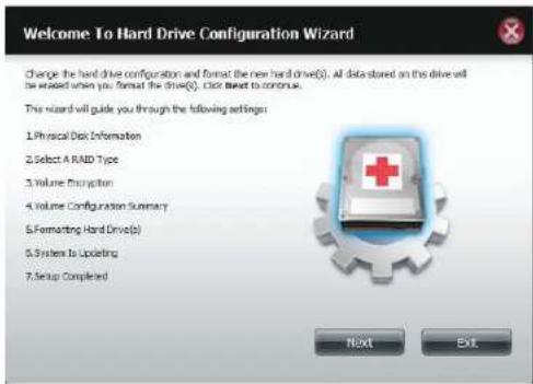
Hard Drive Configuration Wizard
When you click on the Set RAID type and Re-Format button in the Disk Management-Hard Drive Configuration menu a wizard will start, allowing you to format your drives and create the volume RAID format. The following is an example of a standard volume configuration:
The Hard Drive Configuration page displays the current RAID configuration under 'Current RAID Type'.
Click Set RAID Type and Re-Format.
The Setup Wizard begins.
text_image
ShareCenter™ System Home Applications Management New User Management New User Management New User Management User Manage New User Management User Manage New User Management User Manage New User Management User Manage New User Management User Manage New User Management User Manage New User Management User Manage New User Management User Manage New User Management User Manage New User Management User Manage New User Management User Manage New User Management User Manage New User Management User Manage New UserSet RAID Type and Re-Format

text_image
Welcome To Hard Drive Configuration Wizard Change the hard drive configuration and format the new hard drive(s). All data stored on this drive will be erased when you format the drive(s). Click Next to continue. This wizard will guide you through the following settings: 1.Physical Disk Information 2.Select A RAID Type 3.Volume Encryption 4.Volume Configuration Summary 5Formatting Hard Drive(s) 6.System is Updating 7.Setup Completed Next ExitSection 4 - Configuration
The 'Physical Disk Information' page displays all of the hard drives on the DNS-320L. It shows the array number, vendor, model, serial number, and drive capacity.
Click Next to continue.

text_image
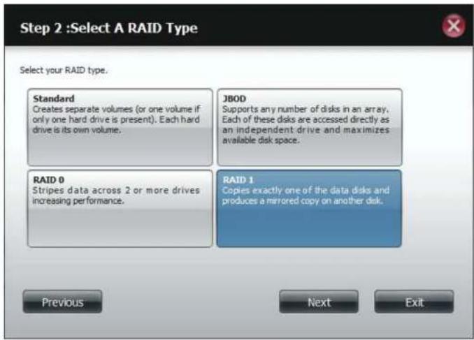
Step 1 :Physical Disk Information This section provides information on your hard drives. It shows the disk array sequence, the manufacturer, the model and serial number, and disk capacity. Disk Vendor Model Serial Number Size Disk1 Hitachi HCS5C1010CLA382 JC0950H02K7LA 931.5 GB Disk2 Hitachi HCS5C1010CLA382 JC0950H02J38A 931.5 GB Previous Next ExitSelect the format you want by clicking on the RAID type box (highlight in blue).
Click Next to continue.

text_image
Step 2 :Select A RAID Type Select your RAID type. Standard Creates separate volumes (or one volume if only one hard drive is present). Each hard drive is its own volume. 3BOD Supports any number of disks in an array. Each of these disks are accessed directly as an independent drive and maximizes available disk space. RAID 0 Stripes data across 2 or more drives increasing performance. RAID 1 Copies exactly one of the data disks and produces a mirrored copy on another disk. Previous Next ExitSelect Standard to create separate volumes for each individual drive.
Click Next to continue.

text_image
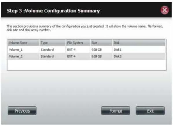
Step 2 :Select A RAID Type Select your RAID type. Standard Creates separate volumes (or one volume if only one hard drive is present). Each hard drive is its own volume. JBOD Supports any number of disks in an array. Each of these disks are accessed directly as an independent drive and maximizes available disk space. RAID 0 Stripes data across 2 or more drives increasing performance. RAID 1 Copies exactly one of the data disks and produces a mirrored copy on another disk. Previous Next ExitThe 'Volume Configuration Summary' shows details on all of the configured drives. Check the details on the list and click Format to continue or click Previous to make changes.
text_image
Step 3 :Volume Configuration Summary This section provides a summary of the configuration you just created. It will show the volume name, file format, disk size and disk array number. Volume Name Type File System Size Disk Volume_1 Standard EXT 4 928 GB Disk1 Volume_2 Standard EXT 4 928 GB Disk2 Previous Format ExitSection 4 - Configuration
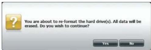
A warning message will appear to inform you that all volumes and data will be formatted and erased.
Click Yes to continue.

text_image
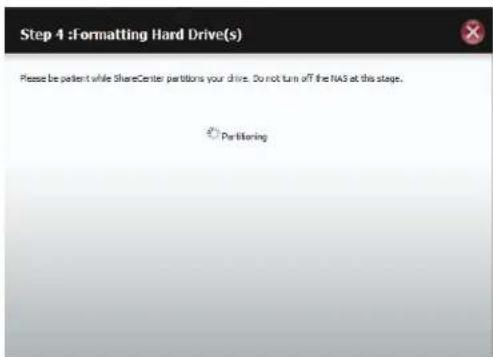
You are about to re-format the hard drive(s). All data will be erased. Do you wish to continue? Yes NoPartitioning will now begin. Please be patient while this process takes place. Do not turn off your NAS during this process.

text_image
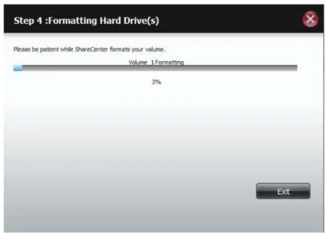
Step 5 :Formatting Hard Drive(s) Please be patent while sharecenter petitions your drive. Do not turn off the NVS at this stage. PartitioningOnce the partition is completed, the formatting process will begin. A graphical bar will show the volume being formatted. Do not turn off your NAS during this process.
If you would like to change your settings at this stage, click Exit.
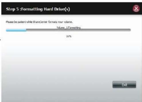
text_image
Step 5 :Formatting Hard Drive(s) Please be patient while ShareCenter formats your volume. Volume_1:Formatting 16% ExitSection 4 - Configuration
The Wizard starts to partition the second drive if you have installed it.
If you would like to change your settings at this stage, click Exit.
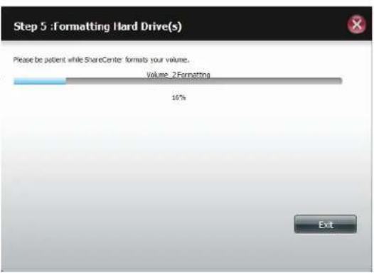
text_image
Step 5 : Formatting Hard Drive(s) Please be patient while ShareCenter formats your volume. Volume 2 Formatting 10% ExitThe system will now update all of the changes made.
Please be patient during this process. Do not turn off your NAS during this process.

text_image
Step 6 :System Is Updating Please be patient while ShareCenter updates your system. Waiting...Section 4 - Configuration
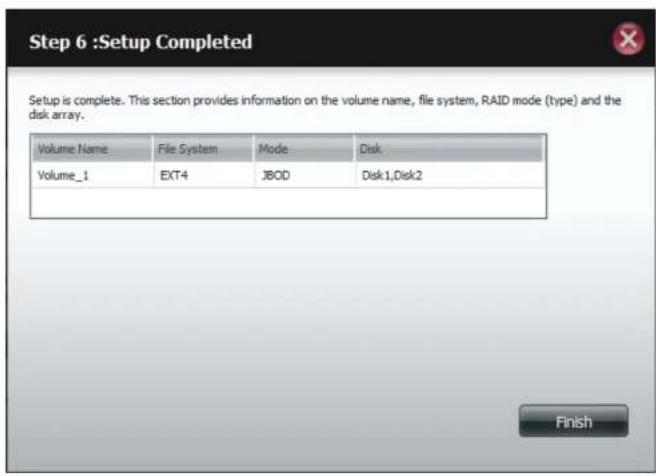
The wizard is now complete. It will show the volume number(s), file system selected, the type of RAID, and the disk formation in the RAID.
Click Finish to complete the process and start using your DNS-320L.
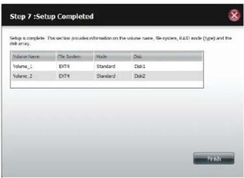
text_image
Step 7 :Setup Completed Setup is complete. The action provides information on the volume name, file system, RAID mode (type) and the disk array. Volume Name File System Mode Disk Volume_1 EXT4 Standard Disk1 Volume_2 EXT4 Standard Disk2 FinishJBOD
Select JBOD to create a single volume from all of the drives.
Click Next to continue.

text_image
Welcome To Hard Drive Configuration Wizard Change the hard drive configuration and format the new hard drive(s). All data stored on this drive will be creased when you format the drive(s). Click Next to continue. This wizard will guide you through the following settings: 1.Physical Disk Information 2.Select A RAID Type 3.Volume Encryption 4.Volume Configuration Summary 5Formatting Hard Drive(s) 6.System Is Updating 7.Setup Completed Next ExitThe wizard displays a Volume Configuration Summary of the drive you want to convert to JBOD.
Click Format to continue or Previous make changes.
text_image
Step 3 :Volume Configuration Summary This section provides a summary of the configuration you just created. It will show the volume name, file format, disk size and disk array number. Volume Name Type File System Size Disk Volume_1 300 EXT 4 $556.68 DiskLDisk2 Previous Format ExitSection 4 - Configuration
A warning message will appear to inform you that all volumes and data will be formatted and erased.
Click Yes to continue.
text_image
You are about to re-format the hard drive(s). All data will be erased. Do you wish to continue? Yes NoWait for the Wizard to prepare the drive for configuration
text_image
Step 4 :Formatting Hard Drive(s) Please be patient while ShareCenter partitions your drive. Do not turn off the NAS at this stage. ParturingSection 4 - Configuration
The Format process begins
text_image
Step 4 :Formatting Hard Drive(s) Please be patient while ShareCenter formats your volume. Volume 1 Formatting 3% ExitThe System Updates

text_image
Step 5 :System Is Updating Please be patient while ShareCenter updates your system. Waiting...Section 4 - Configuration
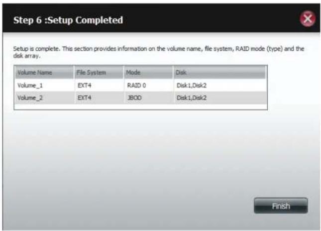
The wizard is now complete. It will show the volume name, file system, and Mode.
Click Finish to complete the process and start using your DNS-320L.
text_image
Step 6 :Setup Completed Setup is complete. This section provides information on the volume name, file system, RAID mode (type) and the disk array. Volume Name File System Mode Disk Volume_1 EXT4 JBOD Disk1,Disk2 FinishThe wizard returns you to the main screen. Here you can see the current RAID Type.
text_image
ShareCenter Home Applications Management Data Track Data Storage Account Application Network Management Application Management System Tools System Data Unit Management Hard Drive Configuration SINJAUL1 Fast Scan Disk Hard Drive Configuration Soft Configuration does you to change your hard drive configuration, or former's newly installed hard drive. Please note that formatting a hard drive will change any data type based on the hard drive. Current MALL Type: Mare_2_2003 Set MALL Type and Ex Format Auto-Exhaust ConfigurationRAID 0
Select RAID 0 (stripes all of the drives).
Click Next to continue.
View the Physical Disk Information.
Click Next to continue.
text_image
Welcome To Hard Drive Configuration Wizard Change the hard drive configuration and format the new hard drive(s). All data stored on the drive will be exceed when you format the drive(s). Click Next to continue. This wizard will guide you through the following settings: 1. Physical Disk Information 2. Select 4 RAID Type 3. Volume Encryption 4. Volume Configuration Summary 5. Formatting Hard Drive(s) 6. System Is Updating 7. Setup Completed Next Exit
text_image
Step 1 :Physical Disk Information This section provides information on your hard drives. It shows the disk array sequence, the manufacturer, the model and serial number, and disk capacity. Disk Vendor Model Small Number Size Disk1 Hitachi HC55C 1010CLA202 DC98301002120A 934.5 GB Disk2 Hitachi HC55C 1010CLA202 DC9830100267LA 934.5 GB Previous Next ExitSection 4 - Configuration
Select the RAID Type. In this example it's RAID 0
Click Next to continue.
Select the size of your RAID 0 configuration.
Click Next to continue.
Section 4 - Configuration
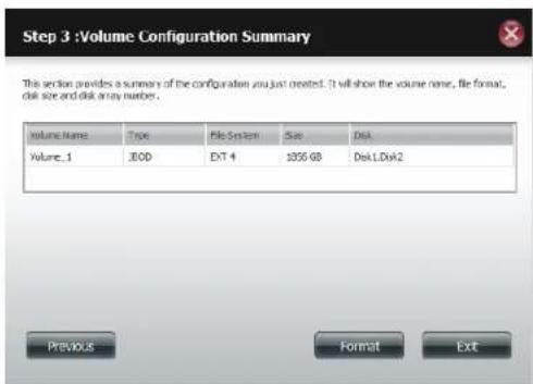
The 'Volume Configuration Summary' shows details on all of the configured drives. Check the details on the list and click Format to continue or click Previous to make changes.
Step 3 :Volume Configuration Summary

This section provides a summary of the configuration you just created. It will show the volume name, file format, disk size and disk array number.
| Volume Name | Type | File System | Size | Disk |
| Volume_1 | RAID 0 | EXT 4 | 344 GB | Disk1, Disk2 |
| Volume_2 | 3BOD | EXT 4 | 1512 GB | Disk1, Disk2 |


A warning message will appear to inform you that all volumes and data will be formatted and erased.
Click Yes to continue.

You are about to re-format the hard drive(s). All data will be erased. Do you wish to continue?

Section 4 - Configuration
Partitioning will now begin. Please be patient while this process takes place. Do not turn off your NAS during this process.
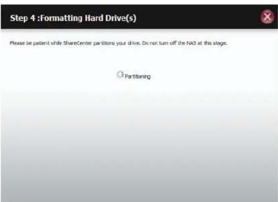
text_image
Step 4 :Formatting Hard Drive(s) Please be patient while ShareCenter partitions your drive. Do not turn off the NAS at this stage. PartitioningThe system formats the First Volume.
If you would like to change your settings at this stage, click Exit.

text_image
Step 4 : Formatting Hard Drive(s) Please be patient while ShareCenter format your volume. Volume_1 Formatting 100% ExitSection 4 - Configuration
The system will now format the second Volume.
Please be patient during this process. Do not turn off your NAS during this process.

text_image
Step 4 : Formatting Hard Drive(s) Please be patient while ShareCenter formats your volume. Volume 2 Formatting 5% ExitThe system will now update all of the changes made.
Please be patient during this process. Do not turn off your NAS during this process.

text_image
Step 5 :System Is Updating Please be patient while ShareCenter updates your system. Waiting...Section 4 - Configuration
The wizard is now complete. It will show the volume number(s), file system selected, the type of RAID, and the disk formation in the RAID.
Click Finish to complete the process and start using your DNS-320L.
The wizard returns you to main Hardware Configuration page. Under Current RAID Type, you can view your changes.
text_image
Step 6 :Setup Completed Setup is complete. This section provides information on the volume name, file system, RAID mode (type) and the disk array. Volume Name File System Mode Disk Volume_1 EXT4 RAID 0 Disk1,Disk2 Volume_2 EXT4 J800 Disk1,Disk2 Finish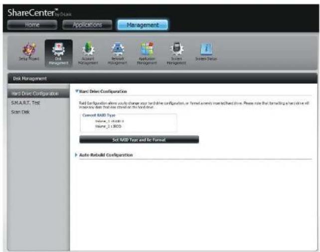
text_image
ShareCenter® My Base Home Applications Management Setup Wizard Disk Management Award Management Review Management Application Management System Management System Status Disk Management Hard Drive Configuration SMAR.T. Test Scan Disk Nanl Drive Configuration Disk Configuration allows you to change your hard drive configuration, or formats a newly installed hard drive. Please note that forwarding a hard drive will multiply data from the next drive on the hard drive. Current RAID Type Volume: 1.0000 GB Volume: 2.1800 GB Set RAID Type and Re-Format Auto-ReluxM ConfigurationRAID 1
Select RAID 1 to mirror all the hard drives.
Click Next to continue.
View the Physical Disk Information.
Click Next to continue.
text_image
Welcome To Hard Drive Configuration Wizard Change the hard drive configuration and format the new hard drive(s). All data stored on the drive will be washed when you format the drive(s). Click Next to continue. This wizard will guide you through the following settings: 1. Physical Disk Information 2. Select A RAID Type 3. Volume Encryption 4. Volume Configuration Summary 5. Formatting Hard Drive(s) 6. System Is Updating 7. Setup Completed Next Exit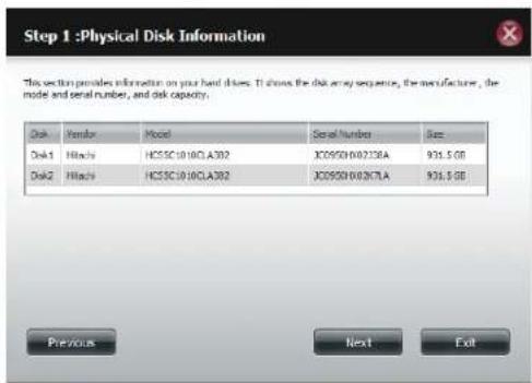
text_image
Step 1 :Physical Disk Information This section provides information on your hard drives. It shows the disk array sequence, the manufacturer, the model and serial number, and disk capacity. Disk Vendor Model Serial Number Dias Disk1 Hlocks HC55C1010CLA392 XJ0950X00236A 935.5 GB Disk2 Hlocks HC55C1010CLA392 XJ0950X00267LA 935.5 GB Previous Next ExitSection 4 - Configuration
Select the RAID TYPE you want
Click Next to continue.
Enter the amount of disk space you would like to assign to the first volume for RAID 1.
Click Next to continue.
text_image
Step 2 :Select A RAID Type Select your RAID type. Standard Creates separate volumes (or one volume if only one hard drive is present). Each hard drive is its own volume. JBOD Supports any number of disks in an array. Each of these disks are accessed directly as an independent drive and maximizes available disk space. RAID 0 Stripes data across 2 or more drives increasing performance. RAID 1 Copies exactly one of the data disks and produces a mirrored copy on another disk. Previous Next Exit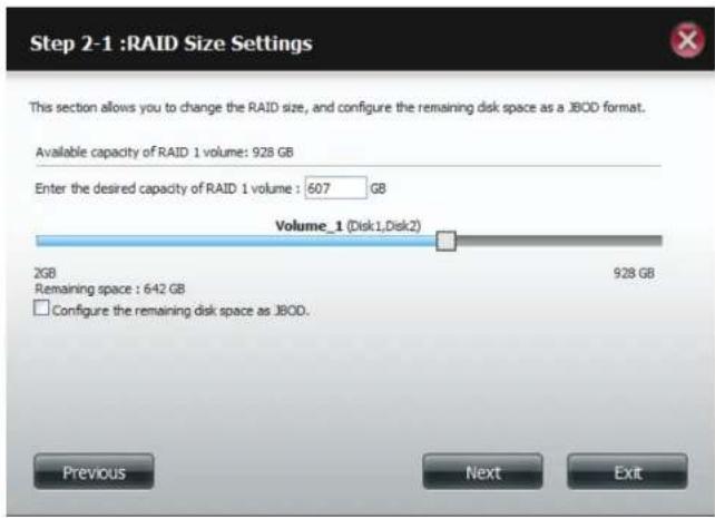
text_image
Step 2-1 :RAID Size Settings This section allows you to change the RAID size, and configure the remaining disk space as a JBOD format. Available capacity of RAID 1 volume: 928 GB Enter the desired capacity of RAID 1 volume : 607 GB Volume_1 (Disk1, Disk2) 2GB Remaining space : 642 GB Configure the remaining disk space as JBOD. 928 GB Previous Next ExitSection 4 - Configuration
Click Enable Auto-Rebuild to automatically rebuild a failed drive if it has been replaced with a new one.
Select Disable Auto-Rebuild if you want to start the rebuild process manually after replacing a failed drive.
Click Next to continue.

text_image
Step 2-2 :Auto-Rebuild Settings This section allows you to rebuild the RAID if it becomes corrupted. Select Enable Auto-Rebuild to automatically rebuild the RAID or select Disable Auto-Rebuild to diagnose it in another manner. Enable Auto-Rebuild Disable Auto-Rebuild Previous Next ExitThe Volume Configuration Summary shows the Volume Name, Type, File System, and size of the RAID volume.
Click Format to continue.

text_image
Step 3 :Volume Configuration Summary This section provides a summary of the configuration you just created. It will show the volume name, file format, disk size and disk array number. Volume Name Type File System Size Disk Volume_1 RAID 1 EXT 4 607 GB Disk1,Disk2 Previous Format ExitSection 4 - Configuration
A warning message will appear, stating that your device will have some latency.
Click Yes to continue.
Partitioning will now begin. Please be patient while this process takes place. Do not turn off your NAS during this process.

text_image
You are about to re-format the hard drive(s). All data will be erased. Do you wish to continue? Yes No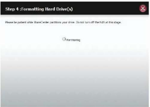
text_image
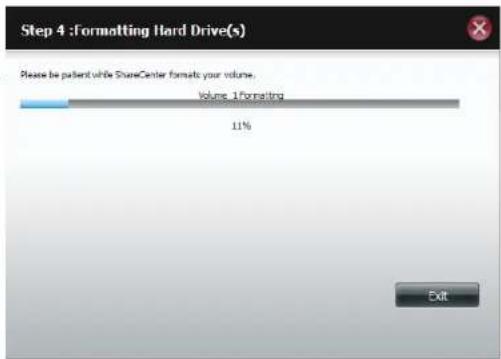
Step 4 : Formatting Hard Drive(s) Please be patient while ShareCenter petitions your drive. Do not turn off the N25 at this stage. ParteningThe system formats the First Volume.
If you would like to change your settings at this stage, click Exit.
text_image
Step 4 :Formatting Hard Drive(s) Please be patient while ShareCenter format your volume. Volume: 1 formatting 11% ExitSection 4 - Configuration
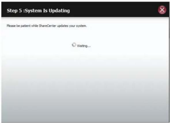
The system updates.
Click Next to continue.
text_image
Step 5 :System Is Updating Please be patient while ShareCenter updates your system. Waiting...Setup is complete. Setup provides a Volume Name, File System, and Mode.

text_image
Step 6 :Setup Completed Setup is complete. This section provides information on the volume name, file system, RAID mode (type) and the disk array. Volume Name File System Mode Disk Volume_1 EXT4 RAID 1 Disk1,Disk2 FinishSection 4 - Configuration
Once you have completed the wizard. ShareCenter will return to the main screen.
The RAID 1 configuration you just set will be displayed.
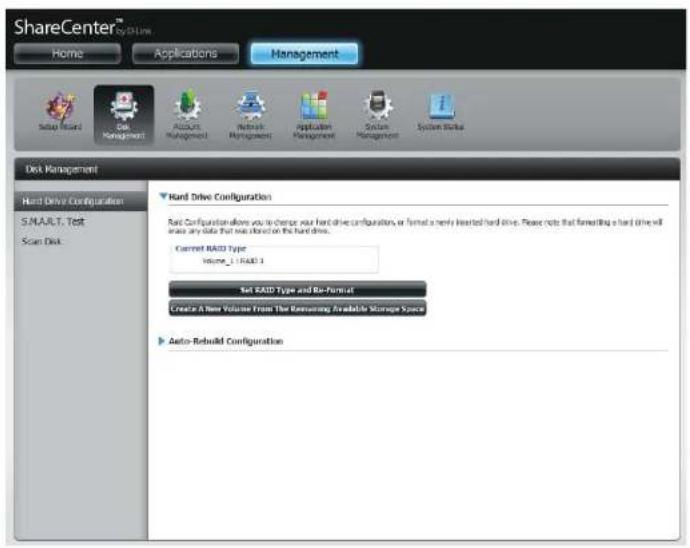
text_image
ShareCenter™ Home Applications Management Setup Wizard Disk Management Accounts Management Network Management Application Management System Management System Start Disk Management Hard Drive Configuration S.MAULT. Test Scan Disk Hard Drive Configuration Soft Configuration allows you to change your hard drive configurations or format a newly installed hard drive. Please note that forwarding a hard drive will share any side that web director on the hard drive. Current RAID Type Volume_1 - RAID 3 Set RAID Type and Re-Format Create A New Volume From The Remaining Available Storage Space Auto-Rebuild ConfigurationUpgrade from Standard Mode to RAID 1
Standard Mode doesn't offer any redundancy and security of data. It is best then to migrate from Standard Mode to RAID 1. To do this follow these instructions:
Step 1 - Insert a second hard drive into the DNS-320L.
natural_image
Hand inserting a battery into a black cylindrical device (no visible text or symbols)Step 2 - Replace the top and restart the DNS-320L.
Section 4 - Configuration
Step 3 - Go to Management, Disk Management, Hard Drive Configuration. There are two options available: Set RAID Type and Re-Format or Format the new drive as Standard type. If you select the latter option your Hard Drive Configuration Wizard shows six procedures but if you select the Set RAID Type and Re-Format, the Hard Drive Configuration Wizard only has four procedures. Take a look at the two images below to compare.
Click Next to continue.
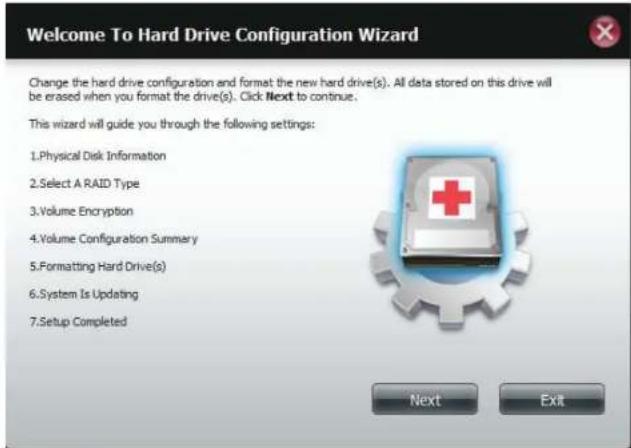
text_image
Welcome To Hard Drive Configuration Wizard Change the hard drive configuration and format the new hard drive(s). All data stored on this drive will be erased when you format the drive(s). Click Next to continue. This wizard will guide you through the following settings: 1.Physical Disk Information 2.Select A RAID Type 3.Volume Encryption 4.Volume Configuration Summary 5Formatting Hard Drive(s) 6.System Is Updating 7.Setup Completed Next ExitFormat the new drive as Standard type.
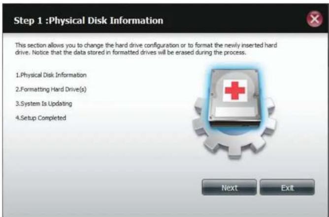
text_image
Step 1 :Physical Disk Information This section allows you to change the hard drive configuration or to format the newly inserted hard drive. Notice that the data stored in formatted drives will be erased during the process. 1.Physical Disk Information 2 Formatting Hard Drive(s) 3.System Is Updating 4.Setup Completed Next ExitSet RAID Type and Re-Format.
Section 4 - Configuration
Step 4 - Under Physical Disk Information, you will be able to see the drive you just installed. It provides the slot location, vendor, model number, serial number, and disk size.
Just below this informational box is a checkbox that offers you the option to Reconfigure the drive to RAID 1. Click the checkbox to proceed.
Click Next to continue.
Step 5 - Under Auto-Rebuild Settings, select whether you want to enable auto rebuild or disable auto rebuild.
Click Next to continue.
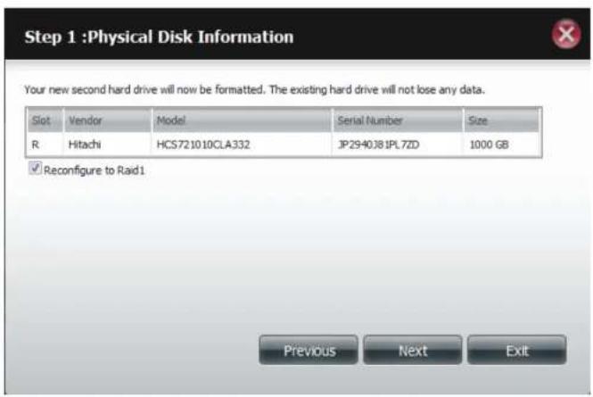
text_image
Step 1 :Physical Disk Information Your new second hard drive will now be formatted. The existing hard drive will not lose any data. Slot Vendor Model Serial Number Size R Hitachi HCS721010CLA332 JP2940J81PL7ZD 1000 GB ✓ Reconfigure to Raid1 Previous Next Exit
text_image
Step 1-1 :Auto-Rebuild Settings This section allows you to change the hard drive configuration or to format the newly inserted hard drive. Notice that the data stored in formatted drives will be erased during the process. Begin by clicking on Next. Enable Auto-Rebuild Disable Auto-Rebuild Previous Next ExitSection 4 - Configuration
Step 6 - A warning message will appear prompting you to confirm whether you want to format your hard drive. Click Yes to continue or No to exit.
Click Next to continue.
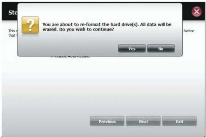
text_image
Ste This is that I You are about to re-format the hard drive(s). All data will be erased. Do you wish to continue? Yes No Notice Previous Next ExitStep 7 - The software communicates with the hardware to build a list.

text_image
Step 1-1 :Auto-Rebuild Settings This section allows you to change the hard drive configuration or to format the newly inserted hard drive. Notice that the data stored in formatted drives will be erased during the process. Waiting...Section 4 - Configuration
Step 6 - The Wizard formats the hard drive.
Click Next to continue.
Step 7 - The System updates.
Click Next to continue.
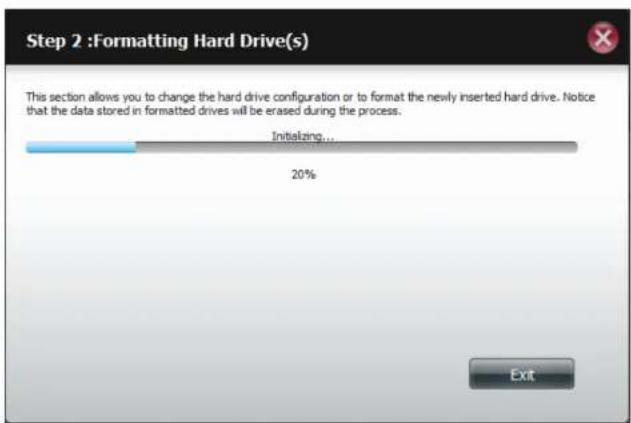
text_image
Step 2 :Formatting Hard Drive(s) This section allows you to change the hard drive configuration or to format the newly inserted hard drive. Notice that the data stored in formatted drives will be erased during the process. Initializing... 20% Exit
text_image
Step 3 :System Is Updating This section allows you to change the hard drive configuration or to format the newly inserted hard drive. Notice that the data stored in formatted drives will be erased during the process. Waiting...Section 4 - Configuration
Step 8 - Setup is completed when it shows final information on the slot, vendor, model number, and serial number.
Click Finish to continue.
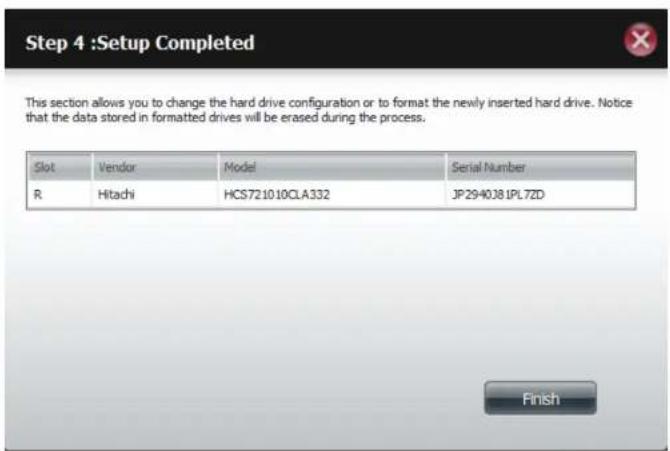
text_image
Step 4 :Setup Completed This section allows you to change the hard drive configuration or to format the newly inserted hard drive. Notice that the data stored in formatted drives will be erased during the process. Slot Vendor Model Serial Number R Hitachi HCS721010CLA332 JP2940381PL72D FinishStep 9 - The wizard returns to the main Hard Drive Configuration

text_image
ShareCenter® by Oracle My Favorites Applications Management Auto Rebuild Data Management Account Management Networks Management Application Management Survey Management Epsilon Style Disk Management Hard Drive Configuration S.M.A.R.T. Test Scan Disk Hard Drive Configuration Read Configuration allows you to change your hard drive configuration, or format a newly inserted hard drive. Please note that formatting a hard drive will ensure any data that you stored on the hard drive. Current RAID Type volume_1 : Standard Set RAID Type and Re-Format Create A New Volume From The Remaining Available Storage Space Auto Rebuild ConfigurationS.M.A.R.T. Test
S.M.A.R.T stands for "Self-Monitoring, Analysis, and Reporting Technology". This is a system on a hard drive used to monitor and report on the health of the drive. If the HD is grayed out, then it does not support S.M.A.R.T.
To run the S.M.A.R.T test, select the hard drive you wish to perform the S.M.A.R.T test on. Select whether to run a Quick or Extended S.M.A.R.T test. Then click Start to run the test. Click the Create Schedule button to run the test at a pre-determined time and date.
The Quick Test usually takes less than 10 minutes. This test will check the electrical, mechanical, and read performance of the hard drive. The results are displayed as Passed/Failed on the web UI and can also be sent as an e-mail alert.
The Extended Test requires a lot more time to complete. However, it is a more thorough when compared to the Quick Test
A warning message will prompt you to stop all services and network activity.
Click Yes to continue the Quick S.M.A.R.T. test.
The test will run and a percentage completed will display under the Progress Tab.
The Start button will change to a Stop button.
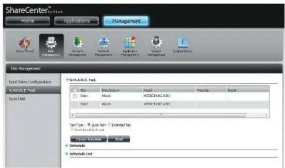
text_image
ShareCenter® For Links Home Applications Management File Edit View Tools Help Tools Help Tools Help Tools Help Tools Help Tools Help Tools Help Tools Help Tools Help Tools Help Tools Help Tools Help Tools Help Tools Help Tools Help Tools Help Tools Help Tools Help Tools Help Tools Help Tools Help Tools Help Tools Help Tools Help Tools Help Tools Help Tools Help Tools Help Tools Help Tools Help Tools Help Tools Help Tools Help Tools Help Tools Help Tools Help Tools Help Tools Help Tools Help Tools Help Tools Help Tools Help Tools Help Tools Help Tools Help Tools Help Tools Help Tools Help Tools Help Tools Help Tools help File Edit View Tools Help Tools Help Tools Help Tools Help Tools Help Tools Help Tools Help Tools Help Tools Help Tools Help Tools Help Tools Help Tools Help Tools Help Tools Help Tools Help Tools Help Tools Help Tools Help Tools Help Tools Help Tools Help Tools Help Tools Help Tools Help Tools Help Tools Help Tools Help Tools Help Tools Help Tools Help Tools Help Tools Help Tools Help Tools Help Tools Help Tools Help Tools Help Tools Help Tools Help Tools Help Tools Help Tools Help Tools Help Tools Help Tools Help Tools Help Tools help Test Type: Quick Test Extended Test Test type: Quick Test Create Schedule List Schedule List START Text START Text Start End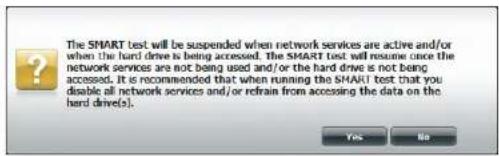
text_image
The SMART test will be suspended when network services are active and/or when the hard drive is being accessed. The SMART test will resume once the network services are not being used and/or the hard drive is not being accessed. It is recommended that when running the SMART test that you disable all network services and/or refrain from accessing the data on the hard drive(s). Yes No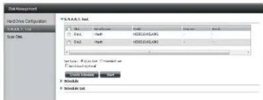
text_image
Disk Management Hard-Drive Configuration S.N.A.R.S. Ltd Scan Data S.N.A.R.S. Ltd Start End Schedule Start Schedule Schedule List Start Schedule Schedule ListSection 4 - Configuration
When the test is complete, the results will be displayed in the Result column.
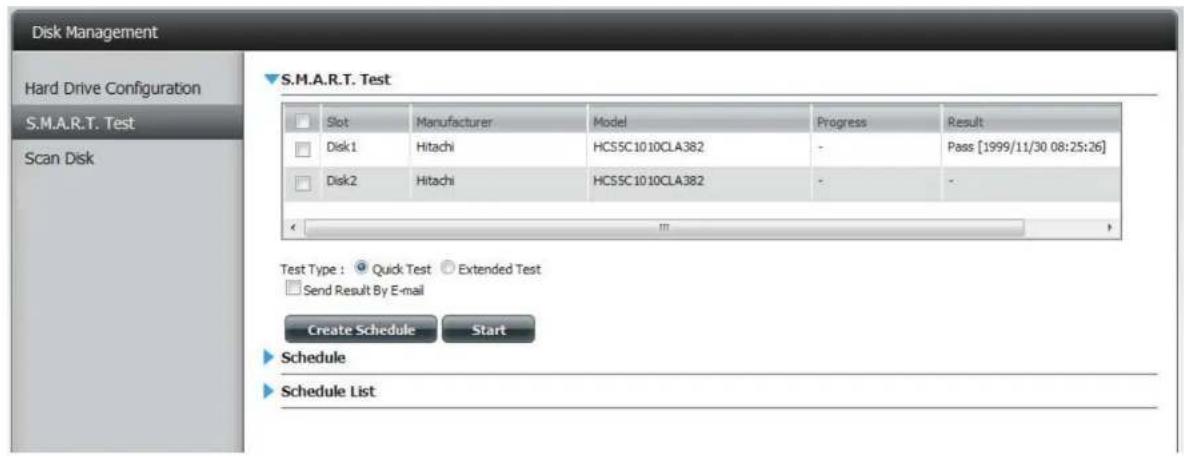
text_image
Disk Management Hard Drive Configuration S.M.A.R.T. Test Scan Disk S.M.A.R.T. Test Slot Manufacturer.Model Progress(Result)Result Disk1 Hitachi HCS5C1010CLA382 - Pass [1999/11/30 08:25:26] Disk2 Hitachi HCS5C1010CLA382 - - Test Type : Quick Test Extended Test Send Result By E-mail Create Schedule Start Schedule Schedule ListCreating a Schedule
To create a schedule, select the disks/volumes to run the test on. Under Schedule, select the period (Daily/Weekly/Monthly) and then select the time from the drop-down menu.
Click Create
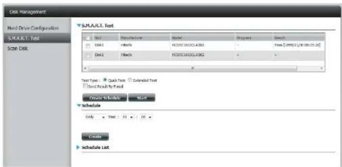
text_image
Disk Management Hard Drive Configuration SMART Test Scan Disk SMART Test Test Manufacture Model Project Result Disk1 Frequency HC31C 0810CL4.582 - Press [099] (1) (6) (8) (25.26) Disk2 Frequency HC31C 0810CL4.582 - - Test Type: Quick Test Extended Test Test Result by Read Create Schedule Start Schedule Only Text: 33 160 Create Schedule ListTo view the Schedule List, click on the Schedule List arrow. A new table will appear showing details of the new schedule created.
To delete a schedule, click on the Trash Can.
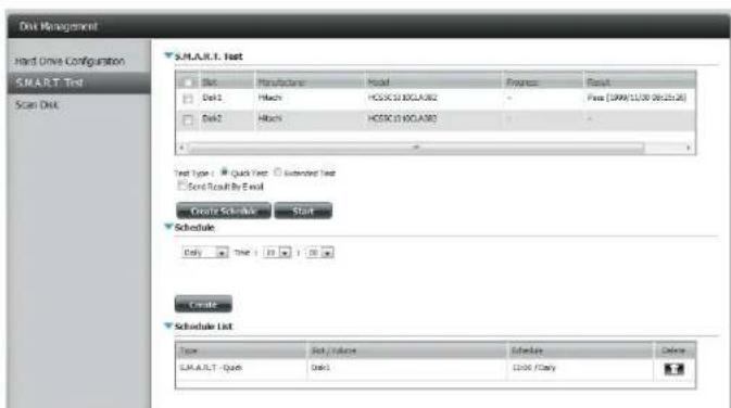
text_image
Disk Management Hard Drive Configuration SMART Test Scan Disk SALULT-1. Test Site Manufacturer Model Engine Result Disk1 Maxch HCSCC10_KOLA382 Free (SPW/11/09 06:25:26) Disk2 Maxch HCSCC10_KOLA383 - Test Type: Quick Test Extended Test Send Result By Email Create Schedule Start Schedule Only TIME: 11:00:1:00:00 Create Schedule List Load / Load1 Load1 Schedule Delete SALULT - QuickScan Disk
Scan Disk provides a method to test the disk's file system on your ShareCenter. Scan Disk scans your disks file system for errors and/or corruption.
Click Management, Disk Management, and then Scan Disk.

text_image
ShareCenter™ Home Applications Management Store Read Data Management Account Management System Management Application Management System Management System Tools Disk Management Hard Drive Configuration SMART Test Scan Disk Scan Disk Volume 1 Volume 2 New DiskSelect the volume from the drop-down list you wish to scan.
Click Scan Disk
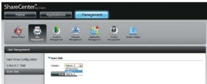
text_image
ShareCenter™ by D Link Home Applications Management Dissu Shared Disk Management Account Management Network Management Application Management System Management System Status Disk Management Hard Drive Configuration S.PALU.R.T. Test Scan Disk Scan Disk Volume: Volume 1 All volume() Scan Volume 1Section 4 - Configuration
A warning message will prompt you to stop running all services (hard drive and network activity).
Click Yes to proceed or No to cancel.

text_image
Suspend all data transmissions and data activity to the hard drive(s) before starting scan disk. It is also recommended to suspend all network activity. Yes NoThe DNS-320L will initialize the volume(s) and begin scanning.
Please wait while the software scans the volume(s) or click Exit to cancel the scan.

text_image
Scan Disk Please wait while the software scans your system. Click the Exit button to cancel the scan. Initiating... 0% ExitWhen the scan is complete, the table will either display Success or Failure.
Click Finish to exit.
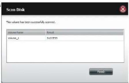
text_image
Scan Disk This volume has been successfully scanned. Volume Name Result Volume_1 SUCCESS Finish:Account Management
Users / Groups
Creating a Single User
The Users/Groups menu is used to create and manage user and group accounts. Up to 256 users and 32 groups can be created. By default, all users have read and write access to all folders. However access rules can be created and edited in the Network Shares menu.
Click Management > Account Management.
Click Users/Groups on the left side and then click Create.

text_image
ShareCenter® Home Applications Management User Group Management Tools Help Account Management Users / Groups Quote Network Shares Admin Password User Settings Driver Notify Delete Export Tools Book Items Downloads 200 Page 1 of 2 H Remaining Use List ItemsThe User Setup Wizard will appear.
Click Next to continue.
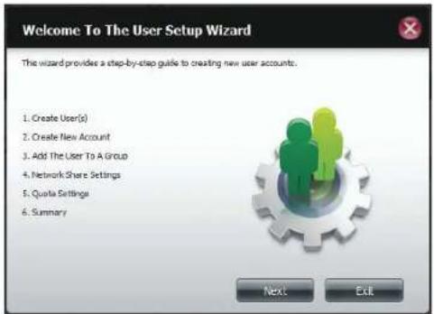
text_image
Welcome To The User Setup Wizard The wizard provides a step-by-step guide to creating new user accounts. 1. Create User(s) 2. Create New Account 3. Add The User To A Group 4. Network Share Settings 5. Quota Settings 6. Summary Next ExitSection 4 - Configuration
Step 1 - Select Create a Single User and then click Next to continue.
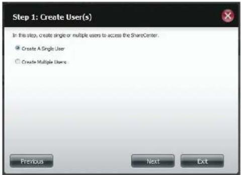
text_image
Step 1: Create User(s) In this step, create single or multiple users to access the ShareCenter. ● Create A Single User ○ Create Multiple Users: Previous Next ExitStep 2 - Enter the user name and password for the new user and then click Next to continue.
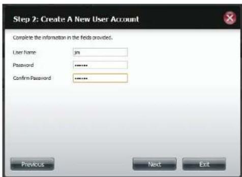
text_image
Step 2: Create A New User Account Complete the information in the fields provided. User Name: Password Confirm Password Previous Next ExitSection 4 - Configuration
Step 3 - Add the user to a group by clicking the Group checkbox. Click Next to continue.

text_image
Step 3: Add The User To A Group No Group(s) have been added to the HAS Previous Next ExitStep 4 - Select the network share settings. Select Read Only, Read/Write, or Deny Access. Click Next to continue.

text_image
Step 4: Network Share Settings Share Name Read Only Read / Write Deny Access Volume_1 Volume_2 10 Page 1 of 1 Deploying 1 to 3 of 3 items Previous Next ExitSection 4 - Configuration
Assign Privileges/Access Methods to the useSelect either FTP or WebDAV. CIFS and AFP are set as default.
• CIFS is short for Common Internet File System.
• AFP is short for Apple Filing Protocol.
- FTP is short for File Transfer Protocol.
- WebDAV is short for Web-based Distribution, Authoring, and Versioning.
Click Next to continue.
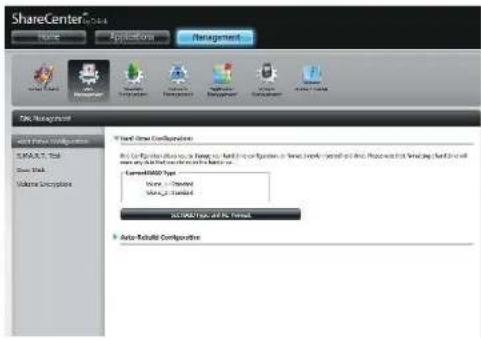
text_image
ShareCenter Home Application Management SNC Management Direct/Stream Configurations D:\Program Files\Outs\Invent\Outs\Invent\Outs\Invent\Outs\Invent\Outs\Invent\Outs\Invent\Outs\Invent\Outs\Invent Current/Stream Type Name: - Document Status: Standard ACI/MSO Type and No. Status Auto-Release ConfigurationsSelect the volumes the user can have WebDAV access to and then select whether to give Read Only or Read/Write rights.
Click Next to continue.

text_image
Step 1: Select Share Folder volume_2 music new Previous Next ExitSection 4 - Configuration
Step 5 - Enter the amount of disk space you wish to assign the user on each volume. Enter zero to provide unlimited disk space to the user. Click Next to continue.
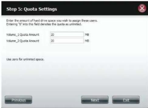
text_image
Step 5: Quota Settings Enter the amount of hard drive space you wish to assign these users. Entering "0" into this field denotes the quota as unlimited. Volume_1 Quota Amount 20 MB Volume_2 Quota Amount 20 MB Use zero for unlimited space. Previous Next ExitStep 6 - The final step is a summary of all the configurations you made. Click Finish to accept the changes or click Exit to cancel the changes.

text_image
Step 6: Summary This completes the wizard. Click Previous to review your settings. Click Finish to save the settings. User Name jin Group Name Read Only Volume_1, Read / Write Volume_2 Denry Access Application List FTP/Webday Previous Finish ExitCreating Multiple Users
Step 1 - Select Create Multiple Users and then click Next to continue.

text_image
Step 1: Create User(s) In this step, create single or multiple users to access the ShareCenter. ○ Create A Single User ● Create Multiple Users Previous Next ExitStep 2 - Enter the following information:
Enter a username.
Enter the account prefix (Eg. this could be a department in the company).
Enter the amount of users you want to create. Next to the input field is the remaining amount of users you can add to the NAS.
Enter a password and confirm it.
Click Next to continue.
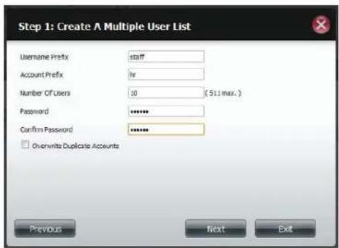
text_image
Step 1: Create A Multiple User List Username Prefix staff Account Prefix Ih Number Of Users 10 (511 max.) Password ****** Confirm Password ****** □ Overwrite Duplicate Accounts Previous Next ExitSection 4 - Configuration
Step 3 - Add the user(s) to a group by clicking the Group checkbox.
Click Next to continue.

text_image
Step 3: Add The User To A Group No Group(s) have been added to this NAS Previous Next ExitStep 4 - Select the network share settings. Select Read Only, Read/Write, or Deny Access. Click Next to continue.
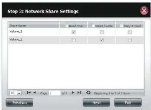
text_image
Step 3: Network Share Settings Share Name Read Only Read / Write Barry Access Volume_1 Volume_2 10 Page 1 w/1 Displaying 1 to 3 of 5 items Previous Next ExitSection 4 - Configuration
Assign Privileges/Access Methods to the user(s). Select FTP. CIFS and AFP are set as default.
• CIFS is short for Common Internet File System.
• AFP is short for Apple Filing Protocol.
- FTP is short for File Transfer Protocol.
Click Next to continue.

text_image
Step 4-1: Assign Privileges - Access Methods Check the service you wish to deploy. The ones previewed out is set by default. ✓ CPS □ AFP ✓ FTP Previous Next ExitStep 5 - Enter the amount of disk space you wish to assign the user(s) on each volume. Type 0 to provide unlimited disk space to the user(s).
Click Next to continue.
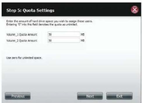
text_image
Step 5: Quota Settings Enter the amount of hard drive space you wish to assign these users. Entering "0" into this field denotes the quota as unlimited. Volume_1 Quote Amount: 50 MB Volume_2 Quote Amount: 50 MB Use zero for unlimited space. Previous Next ExitSection 4 - Configuration
Step 6 - The final step is a summary of all the configurations you made. Click Finish to accept the changes or click Exit to cancel the changes.
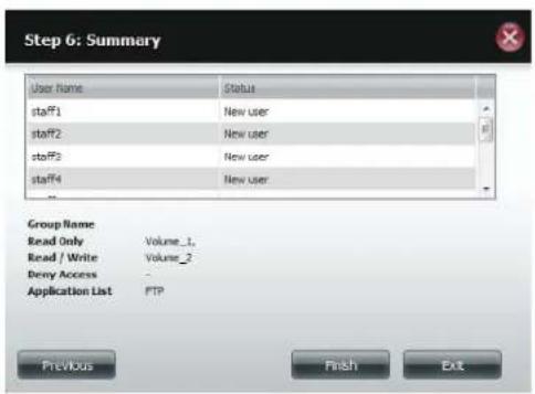
text_image
Step 6: Summary User Name Status staff1 New user staff2 New user staff3 New user staff4 New user Group Name Read Only Volume_1. Read / Write Volume_2 Deny Access Application List FTP Previous Finish ExitThe User Settings window will show a list of the users created.

text_image
ShareCenter My Favorites Applications Management Account Management System Groups User Select Shares Active/Forward Database/No System Best Settings Name: Address: Email: Email: Email: Email: Email: Email: Email: Email: Email: Email: Email: Email: Email: Email: Email: Email: Email: Email: Email: Email: Email: Email: Email: Email: Email: Email: Email: Email: Email: Email: Email: Email: Email: Email: Email: Email: Email: Email: Email: Email: Email: Email: Email: Email: Email: Email: Email: Email: Email: Email: Email Edit SettingsModify Users
Step 1 - Click the user you wish to modify. The user will be highlighted in red.
Click Modify to continue.
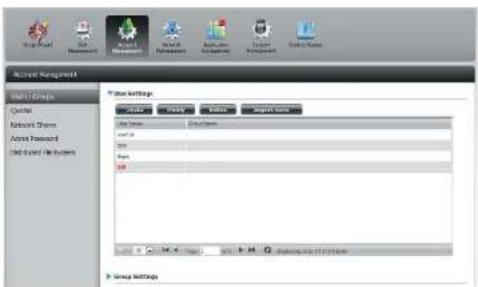
text_image
Active Management Multi Groups Quoted Network Drivers Address Password Child-Isled Methods User Attribute: Category: Group Name: Group Address: Group Name: Group Name: Group Name: Group Name: Group Name: Group Name: Group Name: Group Name: Group Name: Group Name: Group Name: Group Name: Group Name: Group Name: Group Name: Group Name: Group Name: Group Name: Group Name: Group Name: Group Name: Group Name: Group Name: Group Name: Group Name: Group NAME: Group NAME: Group NAME: Group NAME: Group NAME: Group NAME: Group NAME: Group NAME: Group NAME: Group NAME: Group NAME: Group NAME: Group NAME: Group NAME: Group NAME: Group NAME: Group NAME: Group NAME: Group NAME: Group NAME: Group NAME: Group NAME: Group NAME: Group NAME: Group NAME: Group Name: Group NAME: Group NAME: Group NAME: Group NAME: Group NAME: Group NAME: Group NAME: Group NAME: Group NAME: Group NAME: Group NAME: Group NAME: Group NAME: Group NAME: Group NAME: Group NAME: Group NAME: Group NAME: Group NAME: Group NAME: Group NAME: Group NAME: Group NAME: Group Name: Group Name: Group NAME: Group NAME: Group NAME: Group NAME: Group NAME: Group NAME: Group NAME: Group NAME: Group NAME: Group NAME: Group NAME: Group NAME: Group NAME: Group NAME: Group NAME: Group NAME: Group NAME: Group NAME: Group NAME: Group NAME: Group NAME: Group NAME: Group Name: Group NAME: Group Name: Group NAME: Group NAME: Group NAME: Group NAME: Group NAME: Group NAME: Group NAME: Group NAME: Group NAME: Group NAME: Group NAME: Group NAME: Group NAME: Group NAME: Group NAME: Group NAME: Group NAME: Group NAME: Group NAME: Group NAME: Group NAME: Group NAME: Group Name: Group Name: Group Name: Group NAME: Group NAME: Group NAME: Group NAME: Group NAME: Group NAME: Group NAME: Group NAME: Group NAME: Group NAME: Group NAME: Group NAME: Group NAME: Group NAME: Group NAME: Group NAME: Group NAME: Group NAME: Group NAME: Group NAME: Group NAME: Group Name: Group NAME: Group NAME: Group Name: Group NAME: Group NAME: Group NAME: Group NAME: Group NAME: Group NAME: Group NAME: Group NAME: Group NAME: Group NAME: Group NAME: Group NAME: Group NAME: Group NAME: Group NAME: Group NAME: Group NAME: Group NAME: Group NAME: Group NAME: Group NAME: Group Name: GROUP ANTESLA GROUP ANTESLA GROUP ANTESLA GROUP ANTESLA GROUP ANTESLA GROUP ANTESLA GROUP ANTESLA GROUP ANTESLA GROUP ANTESLA GROUP ANTESLA GROUP ANTESLA GROUP ANTESLA GROUP ANTESLA GROUP ANTESLA GROUP ANTESLA GROUP ANTESLA GROUP ANTESLA GROUP ANTESLA GROUP ANTESLA GROUP ANTESLA GROUP ANTESLAStep 2 - The User Setup Wizard will appear.
Click Next to continue.
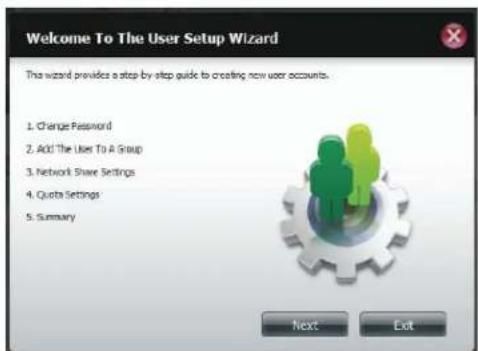
text_image
Welcome To The User Setup Wizard This wizard provides a step-by-step guide to creating new user accounts. 1. Change Password 2. Add: The User To A Group 3. Network Share Settings 4. Quota Settings 5. Summary Next ExitSection 4 - Configuration
Step 3 - Change the username or password. Click Next to continue.

text_image
Step 1: Change Password User Name BI Password****** Confirm Password****** Previous Next Stop ExitStep 4 - Change the Network Share Settings. Click Next to continue.
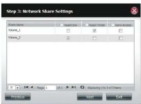
text_image
Step 3: Network Share Settings Share Name Read Only Read / Write Deny Access Volume_1 Volume_2 10 Page 1 of 1 Displaying 1 to 3 of 5 items Previous Next ExitStep 5 - Assign Privileges/Access Methods for the user Select either FTP or WebDAV. CIFS and AFP are set as default.
• CIFS is short for Common Internet File System.
• AFP is short for Apple Filing Protocol.
- FTP is short for File Transfer Protocol.
- WebDAV is short for Web-based Distribution, Authoring, and Versioning.
Click Next to continue.

text_image
Step 3-1: Assign Privileges - Access Methods Check the service you wish to deploy. The once grayed out is set by default. ✓ CIPS ✓ AFP ✓ FTP □ WebDAV Previous Next ExitStep 6 - Enter the re-assigned amount of disk space you wish to assign the user on each volume. Type 0 to provide unlimited disk space to the user.
Click Next to continue.
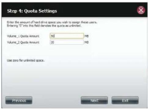
text_image
Step 4: Quota Settings Enter the amount of hard drive space you wish to assign these users. Entering "O" into this field denotes the quota as unlimited. Volume_1 Quota Amount: 30 MB Volume_2 Quota Amount: 30 MB Use zero far unlimited space. Previous Next ExitSection 4 - Configuration
Step 7 - The final step is a summary of all the configurations you made. Click Finish to accept the changes or Exit to cancel the changes.
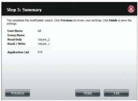
text_image
Step 5: Summary This completes the modification wizard. Click Previous to review your settings. Click Finish to save the settings. User Name bil Group Name Read Only Volume_2 Read / Write Volume_1 Application List FTP Previous Finish ExitStep 8 - A message will appear stating the user details have been changed successfully. Click Yes to exit the wizard.
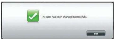
text_image
The user has been changed successfully.Deleting Users
Step 1 - Click the user you wish to delete. The user will be highlighted in red. Click Delete to continue.

text_image
Account Management User Settings User Name: Name: Name: Group SettingsStep 2 - A message will appear prompting you to confirm deleting the user. Click Yes to confirm.
The user is now removed from the list.
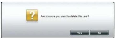
text_image
Are you sure you want to delete this user? Yes NoImporting Users
Step 1 - Click Account Management > Users/Groups > Import Users.

text_image
ShareCenter My Favorites Applications Management Account Management Share Settings Options Reply Help Report Help Edit Options Edit Tools Show SettingsStep 2 - The Import Users Wizard will start. Click Next to continue.
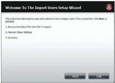
text_image
Welcome To The Import Users Setup Wizard This wizard provides step-by-step instructions on how to import users from a preset list. Click Next to proceed. 1. Browse And Select The User File To Import 2. Network Share Settings 3. Summary. Next ExitSection 4 - Configuration
Step 3 - Click Download to see a sample file.
Check the Overwrite Duplicate Accounts box if this is necessary.
Click Browse to select the file you want to import.
Click Next to continue
Step 4 - Assign the privileges and access methods.
Click Next to continue.

text_image
Step 1: Import The Users File Refer to this example file for parameters. Download Overwrite Duplicate Accounts User List File: Browse... Previous Next Exit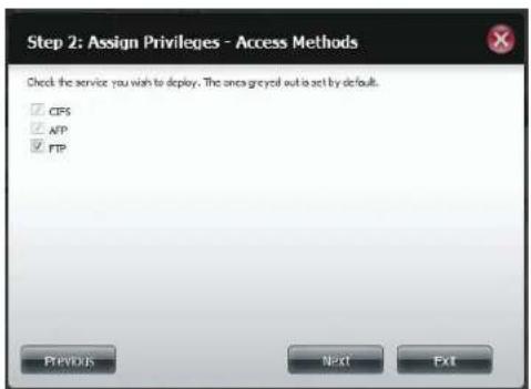
text_image
Step 2: Assign Privileges - Access Methods Check the service you wish to deploy. The area greyed out is set by default. ✓ CPS ✓ AFP ✓ FTP Previous Next ExitSection 4 - Configuration
Step 5 - The Summary will show a list of the imported users. If there are problems with the user list, the wizard will show the errors in red on the table.
Click Finish to close the wizard or go back to change the imported file.
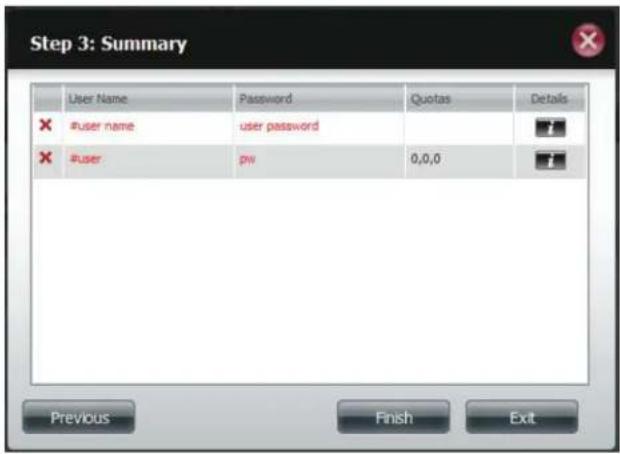
text_image
Step 3: Summary User Name Password Quotas Details #user name (:user password) #user (:p): 0,0,0 Previous Finish ExitCreating a Group
Step 1 - Click Account Management > Users/Groups.
Click the blue arrow next to Group Settings and settings window will appear. Click New to create a new Group.
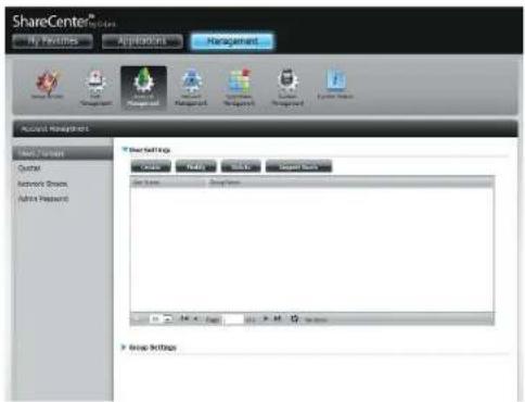
text_image
ShareCenter® My Features Applications Management Account Management Back Viewers Control Network Groups Admin Password Show SettingsStep 2 - The Group Setup Wizard will now start. Click Next to continue.
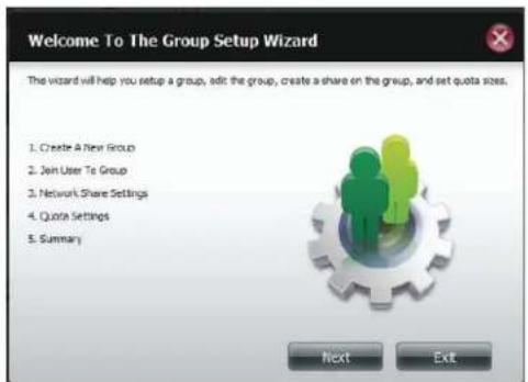
text_image
Welcome To The Group Setup Wizard The wizard will help you setup a group, add the group, create a share on the group, and set quota sizes. 1. Create A New Group 2. Join User To Group 3. Network Share Settings 4. Quote Settings 5. Summary Next ExtSection 4 - Configuration
Step 3 - Enter a Group Name. Click Next to continue

text_image
Step 1: Create A New Group Group Name tech_lab Previous Next ExitStep 4 - Click the checkbox to select the user(s) you wish to add to the group and then click Next to continue.

text_image
Step 2: Join User To Group User Name stafF5 stafF6 stafF7 stafF8 stafF9 stafF10 tom bill Previous Next ExitSection 4 - Configuration
Step 5 - Select the Network Share Settings (read, read/write, deny access) for the corresponding disk volume for the group.
Click Next to continue.

text_image
Step 3: Network Share Settings Share Name Read Only Read / Write Deny Action Volume_1 Volume_2 10 Page 1 of 1 Displaying 1 to 3 of 3 items Previous Next ExitStep 6 - Select the Privileges/Access Methods you want to assign to the group. The greyed out selections are assigned by default.
Click Next to continue.

text_image
Step 3 :Volume Encryption The section allows you to choose which drives you want to encrypt. Volume Name Type Size Encryption Volume_1 RSD 1 70 GB Previous Next ExitSection 4 - Configuration
Step 7 - Select the appropriate WebDAV settings and click Next to continue.
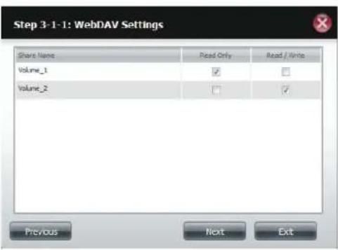
text_image
Step 3-1-1: WebDAV Settings Share Name Read Only Read / Write Volume_1 ✓ □ Volume_2 □ ✓ Previous Next ExitStep 8 - Enter the amount of space you want to assign to the group for each volume. Enter zero to give unlimited disk space to the group. Click Next to continue.
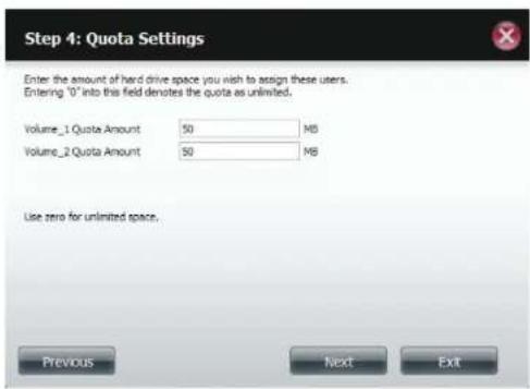
text_image
Step 4: Quota Settings Enter the amount of hard drive space you wish to assign these users. Entering '0' into this field denotes the quota as unlimited. Volume_1 Quote Amount 50 MB Volume_2 Quote Amount 50 MB Use zero for unlimited space. Previous Next ExitSection 4 - Configuration
Step 9 - The wizard is now complete. The last step shows a summary of the group you created. Click Previous to change your settings or Finish to end the wizard.
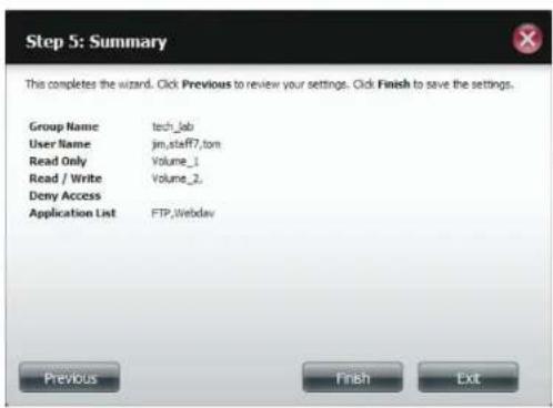
text_image
Step 5: Summary This completes the wizard. Click Previous to review your settings. Click Finish to save the settings. Group Name tech_lab User Name jim_staff7.ton Read Only Volume_1 Read / Write Volume_2 Deny Access Application List FTP.Webdav Previous Finish ExitStep 10 - Under Group Settings, a table will display the group you just created.
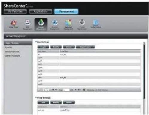
text_image
ShareCenter My Favorites Applications Management Account Management Data / Options Options Network Shares Admin Password Drop Settings Stock Name Stock Name SPT_00 SPT_01 SPT_02 SPT_03 SPT_04 SPT_05 SPT_06 SPT_07 SPT_08 SPT_09 SPT_10 SPT_11 SPT_12 SPT_13 SPT_14 SPT_15 SPT_16 SPT_17 SPT_18 SPT_19 SPT_20 SPT_21 SPT_22 SPT_23 SPT_24 SPT_25 SPT_26 SPT_27 SPT_28 SPT_29 SPT_30 SPT_31 SPT_32 SPT_33 SPT_34 SPT_35 SPT_36 SPT_37 SPT_38 SPT_39 SPT_40 SPT_41 SPT_42 SPT_43 SPT_44 SPT_45 SPT_46 SPT_47 SPT_48 SPT_49 SPT_50 SPT_51 SPT_52 SPT_53 SPT_54 SPT_55 SPT_56 SPT_57 SPT_58 SPT_59 SPT_60 SPT_61 SPT_62 SPT_63 SPT_64 SPT_65 SPT_66 SPT_67 SPT_68 SPT_69 SPT_70 SPT_71 SPT_72 SPT_73 SPT_74 SPT_75 SPT_76 SPT_77 SPT_78 SPT_79 SPT_80 SPT_81 SPT_82 SPT_83 SPT_84 SPT_85 SPT_86 SPT_87 SPT_88 SPT_89 SPT_90 SPT_91 SPT_92 SPT_93 SPT_94 SPT_95 SPT_96 SPT_97 SPT_98 SPT_99 SPT_100Modifying a Group
Step 1 - Click Account Management > Users/Groups.
Click the blue arrow next to Group Settings and the Group Settings table will appear.

text_image
ShareCenter® My Finance AppWizard Management Account Management User / Store Desktop Network Stock Achir Payments T-Store Settings Cash Payoff Cash Export Items Live Share Live Total 24 100.56 0.00% 0.00% 0.00% 0.00% 0.00% 0.00% 0.00% 0.00% 0.00% 0.00% 0.00% 0.00% Group Settings Use Modify Edit Share Shares 38,28 #p.ppt.LienStep 2 - Select the group you want to modify. Your selection will turn red.
Click Modify to change the settings for the Group.

text_image
ShareCenter™ My Favorites Applications Management Account Management Name: Name Address: Network Address Address Password Email: Email: Email: Email: Email: Group Settings Rev Modify Show ShareName ShareName Form1.doc Form1.doc Form1.docSection 4 - Configuration
Step 3 - The Group Setup Wizard will now start. Click Next to continue.
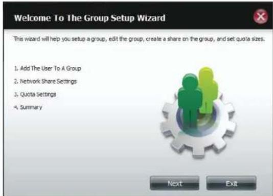
text_image
Welcome To The Group Setup Wizard This wizard will help you setup a group, edit the group, create a share on the group, and set quota sizes. 1. Add The User To A Group 2. Network Share Settings 3. Quota Settings 4. Summary Next ExitStep 4 - Make the necessary modifications to the group and then click Next to continue.

text_image
Step 1: Add The User To A Group User Name jm staff1 staff2 staff3 staff4 staff5 staff6 staff7 Previous Next ExitSection 4 - Configuration
Step 5 - Select the appropriate Network Share Settings (read, read/write, deny access) for the corresponding disk volume for the group. Click Next to continue.
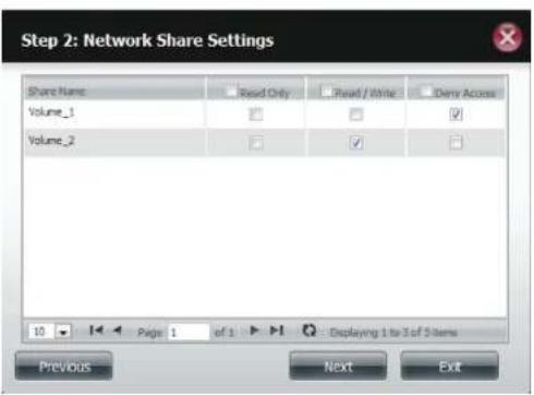
text_image
Step 2: Network Share Settings Share Name Read Only Read / Write Demy Access Volume_1 Volume_2 10 Page 1 of 1 : Displaying 1 to 3 of 5 items Previous Next ExitStep 6 - Select the appropriate privileges you want to assign to the group. The greyed out selections are assigned by default and cannot be modified.
Click Next to continue.
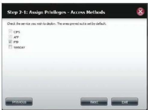
text_image
Step 2-1: Assign Privileges - Access Methods Check the service you wish to deliver. The ones greeted out to set by default. CPS AFP FTP WENDAY Previous Next ExitSection 4 - Configuration
Step 7 - Edit the amount of space you want to assign to the group for each volume. Enter zero to give unlimited disk space to the group.
Click Next to continue.
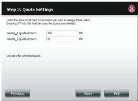
text_image
Step 3: Quota Settings Enter the amount of hard drive space you wish to assign these users. Entering "O" into this field denotes the quota as unlimited. Volume_1 Quota Amount: 100 MB Volume_2 Quota Amount: 20 MB Use zero for unlimited space. Previous Next ExitStep 8 - When editing the quota, make sure the size is not smaller than the user quota on his/her account.
Click Yes to change the quota.

text_image
The quota amount cannot smaller than the user quota amount.(20 ME) Yes Use zero for unlimited space. Previous Next ExitSection 4 - Configuration
Step 9 - The wizard is now complete and will display a summary of the group you edited.
Click Previous to change your settings or Finish to end the wizard. Exit will cancel all changes you made.
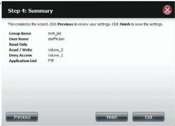
text_image
Step 4: Summary This completes the wizard. Click Previous to review your settings. Click Finish to save the settings. Group Name tech_lab User Name staff4.tom Read Only Read / Write Volume_2 Deny Access Volume_1 Application List FTP Previous Finish ExitDeleting a Group
Step 1 - Select the Group you want to delete and click Delete.

text_image
ShareCenter® Share My Search Applications Management Account Management Share / Groups #N #N #N #N #N #N #N #N #N #N #N #N #N #N #N #N #N #N #N #N #N #N #N #N #N #N #N #N #N #N #N #N #N #NStep 2 - A warning message will appear asking you to verify if you want to delete the Group. Click Yes to delete the Group or No to cancel your decision.

text_image
Are you sure want to delete? Yes NoQuotas
The ShareCenter supports storage quotas for both groups and individuals. Assigning a quota to a group or user will limit the amount of storage allocated. By default, users and groups do not have a quota. Click Account Management and then Quotas on the left side.
Click Enable to activate Quota Settings. The status will now display 'Started' notifying you that the Quota Settings are enabled.
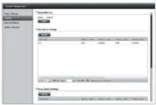
text_image
Account Management Lower Groups Order Network Groups Service Groups Order Settings Order Settings Order Amount Order Amount Order Amount Order Amount Order Amount Order Amount Order Amount Order Amount Order Amount Order Amount Order Amount Order Amount Order Amount Order Amount Order Amount Order Amount Order Amount Order Amount Order Amount Order Amount Order Amount Order Amount Order Amount Order Amount Order Amount Order Amount Order Amount Order Amount Order Amount Order Amount Order Amount Order Amount Order Amount Order AmountTo Modify a User's Quota Settings, click the blue arrow next to User Quota Settings to reveal a table of users.

text_image
Account Management User Groups Edit Network Groups Active Settings Quote Settings Note: 1. Tested helpful Not Quote Settings Name: Name_1 Card Name_2 Card Name_3 Card Name_4 Card P: 2000 2001 2002 2003 Group Quts SettingsSection 4 - Configuration
Select the User you want to modify. Your selection will turn red. Click Modify to change the user's settings.
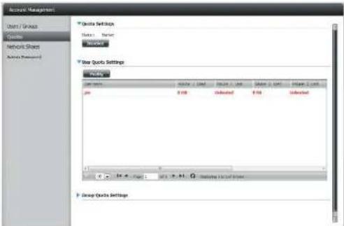
text_image
Audio Management Chart & Groups Cycles Network Shares Actions (Reference) Quote Settings Notes: Marker Worker Bar Quote Settings Value: Value 1 Used Value 2 Used Value 3 Used Value 4 Used Value 5 Used Value 6 Used Value 7 Used Value 8 Used Value 9 Used Value 10 Used Value 11 Used Value 12 Used Value 13 Used Value 14 Used Value 15 Used Value 16 Used Value 17 Used Value 18 Used Value 19 Used Value 20 Used Value 21 Used Value 22 Used Value 23 Used Value 24 Used Value 25 Used Value 26 Used Value 27 Used Value 28 Used Value 29 Used Value 30 Used Value 31 Used Value 32 Used Value 33 Used Value 34 Used Value 35 Used Value 36 Used Value 37 Used Value 38 Used Value 39 Used Value 40 Used Value 41 Used Value 42 Used Value 43 Used Value 44 Used Value 45 Used Value 46 Used Value 47 Used Value 48 Used Value 49 Used Value 50 Used Value 51 Used Value 52 Used Value 53 Used Value 54 Used Value 55 Used Value 56 Used Value 57 Used Value 58 Used Value 59 Used Value 60 Used Value 61 Used Value 62 Used Value 63 Used Value 64 Used Value 65 Used Value 66 Used Value 67 Used Value 68 Used Value 69 Used Value 70 Used Value 71 Used Value 72 Used Value 73 Used Value 74 Used Value 75 Used Value 76 Used Value 77 Used Value 78 Used Value 79 Used Value 80 Used Value 81 Used Value 82 Used Value 83 Used Value 84 Used Value 85 Used Value 86 Used Value 87 Used Value 88 Used Value 89 Used Value 90 Used Value 91 Used Value 92 Used Value 93 Used Value 94 Used Value 95 Used Value 96 Used Value 97 Used Value 98 Used Value 99 UsedThe Quota Settings configuration box will display the user account you want to modify. Enter a new quota amount for each volume.
Click Apply to confirm your settings.
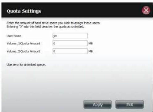
text_image
Quota Settings Enter the amount of hard drive space you wish to assign these users. Entering "0" into this field denotes the quota as unlimited. User Name: jm Volume_1 Quota Amount 0 MB Volume_2 Quota Amount 0 MB Use zero for unlimited space. Apply ExitSection 4 - Configuration
The modified quota settings will be displayed in the table.
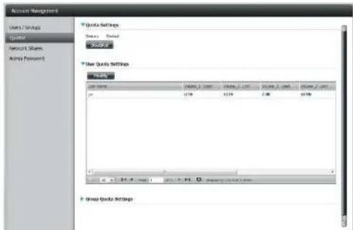
text_image
Account Management Users Tools Explorer Aircraft Shares Access Forward Quick Settings Ready Cancel Quick Use Tools Use Tools Settings Status: Name: 10000000000000000000000000000000000000000000000000000000000000000000000000000000000000 p 17.98 12.59 2.46 16.58 Group Tools SettingsFor Group Quota Settings, click the blue drop-down arrow next to Group Quota Settings to view the group quota table.
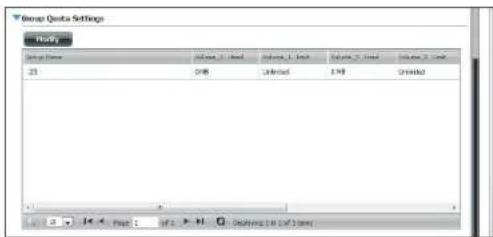
text_image
Group Quote Settings Page 1 Volume 1: 100 Volume 2: 100 Volume 3: 100 Volume 4: 100 Volume 5: 100 Volume 6: 100 Volume 7: 100 Volume 8: 100 Volume 9: 100 Volume 10: 100 Volume 11: 100 Volume 12: 100 Volume 13: 100 Volume 14: 100 Volume 15: 100 Volume 16: 100 Volume 17: 100 Volume 18: 100 Volume 19: 100 Volume 20: 100 Volume 21: 100 Volume 22: 100 Volume 23: 100 Volume 24: 100 Volume 25: 100 Volume 26: 100 Volume 27: 100 Volume 28: 100 Volume 29: 100 Volume 30: 100 Volume 31: 100 Volume 32: 100 Volume 33: 100 Volume 34: 100 Volume 35: 100 Volume 36: 100 Volume 37: 100 Volume 38: 100 Volume 39: 100 Volume 40: 100 Volume 41: 100 Volume 42: 100 Volume 43: 100 Volume 44: 100 Volume 45: 100 Volume 46: 100 Volume 47: 100 Volume 48: 100 Volume 49: 100 Volume 50: 100 Volume 51: 100 Volume 52: 100 Volume 53: 100 Volume 54: 100 Volume 55: 100 Volume 56: 100 Volume 57: 100 Volume 58: 100 Volume 59: 100 Volume 60: 100 Volume 61: 100 Volume 62: 100 Volume 63: 100 Volume 64: 100 Volume 65: 100 Volume 66: 100 Volume 67: 100 Volume 68: 100 Volume 69: 100 Volume 70: 100 Volume 71: 100 Volume 72: 100 Volume 73: 100 Volume 74: 100 Volume 75: 100 Volume 76: 100 Volume 77: 100 Volume 78: 100 Volume 79: 100 Volume 80: 100 Volume 81: 100 Volume 82: 100 Volume 83: 100 Volume 84: 100 Volume 85: 100 Volume 86: 100 Volume 87: 100 Volume 88: 100 Volume 89: 100 Volume 90: 100 Volume 91: 100 Volume 92: 100 Volume 93: 100 Volume 94: 100 Volume 95: 100 Volume 96: 100 Volume 97: 100 Volume 98: 100 Volume 99: 100 Volume 1Q : Figure. (In QF) - H. Drawing [In QF] EmailSection 4 - Configuration
Select the group you want to modify. Your selection will turn red. Click Modify.
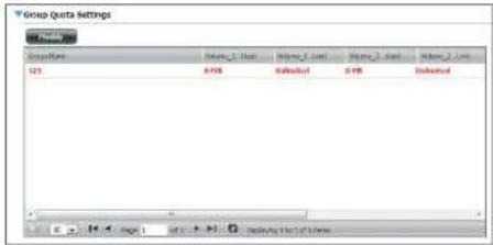
text_image
Group Data Settings Groups Value_1 Value Value_2 Value Value_3 Value Value_4 Value S21 B78 Dedicated B78 DedicatedThe Group Quota Settings screen will display the group you want to modify. Enter a new quota amount for each volume for the current group and click Apply.
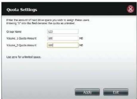
text_image
Quota Settings Enter the amount of hard drive space you wish to assign these users: entering "U" into the field denotes the quota as unlimited. Group Name 123 Volume_1 Quota Amount 100 MS Volume_2 Quota Amount 100 MS Use zero for unlimited space. Apply ExitSection 4 - Configuration
The modified quota settings will be displayed in the table.
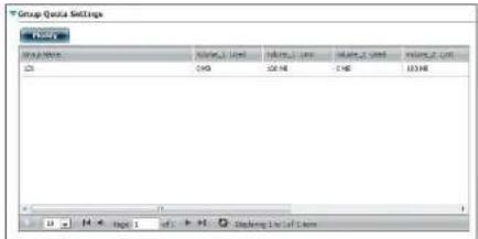
text_image
Group Data Settings Value_1 Value_2 Value_1 Value_2 Value_1 Value_2 Value_1 Value_2 Value_1 Value_2 Value_1 Value_2 Value_1 Value_2 Value_1 Value_2 Value_1 Value_2 Value_1 Value_2 Value_1 Value_2 Value_1 Value_2 Value_1 Value_2 Value_2 Value_1 Value_2 Value_1 Value_2 Value_1 Value_2 Value_1 Value_2 Value_1 Value_2 Value_1 Value_2 Value_1 Value_2 Value_1 Value_2 Value_1 Value_2 Value_1 Value_2 Value_1 Value_2 Value_1 Value_1 Value_2 Value_1 Value_2 Value_1 Value_2 Value_1 Value_2 Value_1 Value_2 Value_1 Value_2 Value_1 Value_2 Value_1 Value_2 Value_1 Value_2 Value_1 Value_2 Value_1 Value_2 Value_1 Value_2 Value_0Network Shares
The Network Shares page allows the user to configure shared folders and rights to specific users and groups. In order to create network access rules, the default rule must be removed first. This can be done simply by clicking on the Delete button. You can also mount .iso files in the ISO Mount Shares settings. When a user has access to a mounted .iso, he/she will also have access to all the files on it.
Network Share/ISO Mount Shares:
The Network Shares Settings window allows the user to add, modify, and remove both new and existing Network Share and ISO Mount Share Settings.
To add a rule click on the New button. To modify an existing rule click on the Modify button. To remove a rule click on the Delete button.
To select a rule, simply click on the rule. Your selection will turn red, indicating it is selected for use.
At the bottom of the table, the user can navigate through pages and also refresh the window by click on the Refresh button.
Click on the Reset Network Shares button to reset the network access list to the default configuration.

text_image
ShareCenter® Name Application Management System Tools Management Network Management System Tools System Management Network Management Network Settings System Tools Network Management Network Project Management Network System Network Project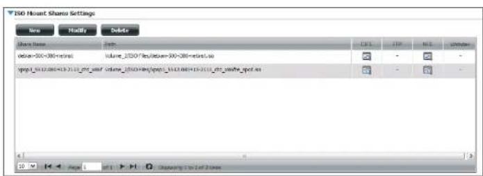
text_image
ISO Mount Share Settings New Modify Delete Share Name Date: Volume_2300 Files Volume_2300-085-0815.xo Volume_2300 Files/Spool_1612.084-16-2111_fct_ydyle_spool.xo C: 1.1 L: 1.1 N: 1.1 Unknown 10 Page 1 Next 1 Outperform To 2 of 2 yearsAdd/Modify Network Shares Wizard
The following section will describe how to add a new Network Share on the ShareCenter. To add a Network Share click on the New button. An easy to configure wizard will launch.
Step 1 - This window welcomes the user to the setup wizard for creating a new network share.
In this wizard the user will be able to:
1) Select share folders.
2) Configure shared folder access rights.
3) Configure network access settings.
4) View a summary of the configuration before completing.
Click Next to continue.
Step 2 - Select the Share Folder from one of the volumes.
Click Next to continue.
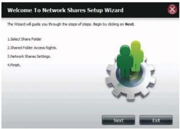
text_image
Welcome To Network Shares Setup Wizard The Wizard will guide you through the steps of steps. Begin by clicking on Next. 1. Select Share Folder 2. Shared Folder Access Rights. 3. Network Shares Settings. 4. Finish.
text_image
Step 1: Select Share Folder Volume_1 Volume_2 music video ISO Files New Previous Next ExitSection 4 - Configuration
Step 3 - Select the user accounts or group which are allowed to access this folder(s). Select All Accounts to allow access to this folder to all the accounts. Select Specific User/Group to only allow certain users or groups access to this folder.
Click Next to continue.

text_image
Step 2: Shared Folder Access Rights Select users to access the shared folder ○ All Accounts ○ Specific User/Group Previous Next ExitStep 4 - Select the appropriate access rights for the share. Options to select from are Read Only, Read/Write, and Deny Access.
This procedure can also be used to block certain users from accessing certain folders.
Click Next to continue.
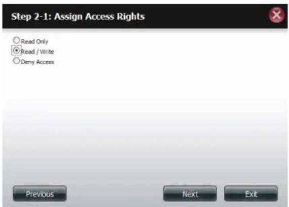
text_image
Step 2-1: Assign Access Rights Read Only Read / Write Deny Access Previous Next ExitSection 4 - Configuration
Step 5 - If you selected Specific User/Group in Step 3, then this step allows you to set the access rights for each User configured on the ShareCenter.
Click Next to continue.

text_image
Step 2-2: Select Users User Name Read Only Read / Write Deny Access user 1 □ □ □ user 2 □ □ □ user 3 □ □ □ 10 Page 1 of 1 Displaying 1 to 3 of 5 items Previous Next ExitStep 6 - If you selected Specific user/Group in Step 3, then this step allows you to set the access rights for each Group configured on the ShareCenter.
Click Next to continue.
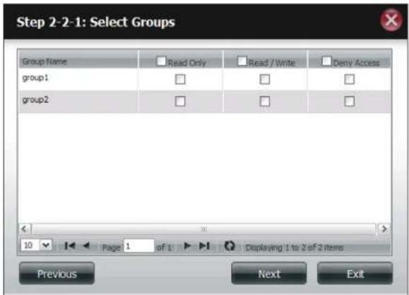
text_image
Step 2-2-1: Select Groups Group Name Read Only Read / Write Deny Access group1 □ □ □ group2 □ □ □ 10 Page 1 of 1 Displaying 1 to 2 of 2 items Previous Next ExitStep 7 - Here you can assign privileges to this share.
Opportunistic locks (oplocks) are a characteristic of the LAN Manager networking protocol implemented in the 32-bit Windows family.
Oplocks are guarantees made by a server for a shared logical volume to its clients. These guarantees inform the Client that a file's content will not be allowed to be changed by the server, or if some change is imminent, the client will be notified before the change is allowed to proceed.
Oplocks are designed to increase network performance when it comes to network file sharing. However it is recommended to set the share oplocks to No (off) when using file-based database applications. When enabled, the file attribute "Map Archive" will be copied as the file is being stored on the ShareCenter.
Click Next to continue.
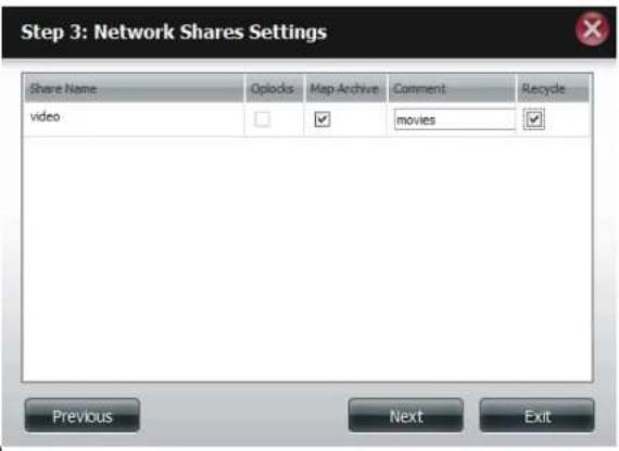
text_image
Step 3: Network Shares Settings Share Name Opilocks Map Archive Comment Recycle video movies Previous Next ExitSection 4 - Configuration
Step 8 - Here you can assign more protocol privileges that a user can use to access this share. Options to choose from are FTP, NFS, and WebDAV. CIFS and AFP are set as default.
• CIFS is short for Common Internet File System.
• AFP is short for Apple Filing Protocol.
- FTP is short for File Transfer Protocol
• NFS is short for Network File System.
- WebDAV is short for Web-based Distributed Authoring and Versioning.
Click Next to continue.
Step 3-1: Assign Privileges - Access Methods

Select which protocols this share should be accessible by. CIFS, AFP is automatically selected by default.
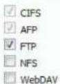
Previous

Section 4 - Configuration
Step 9 - Here you can configure the FTP settings for this share. FTP access can be:
1) FTP Anonymous None (No Access).
2) FTP Anonymous Read Only (Limited Access).
3) FTP Anonymous Read/Write (Full Access).
Click Next to continue.

text_image
Step 3-1-1: FTP Settings FTP Anonymous None FTP Anonymous Read Only FTP Anonymous Read / Write Previous Next ExitIf you checked NFS as an access method to your network share then this step allows you to set the parameters below:
- Host - Allowable host address that can access using NFS (*indicates all hosts)
- Root Squash - Disables writing to the Root owned directories and files on the system when the user has root access privileges.
- Write - provide write permission to the file system.
Click Next to continue.
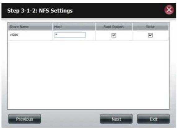
text_image
Step 3-1-2: NFS Settings Share Name Host Root Squash Write video * ✓ ✓ Previous Next ExitSection 4 - Configuration
If you checked WebDAV as an access method, then this step will allow you to set the access parameters.
Click Next to continue.
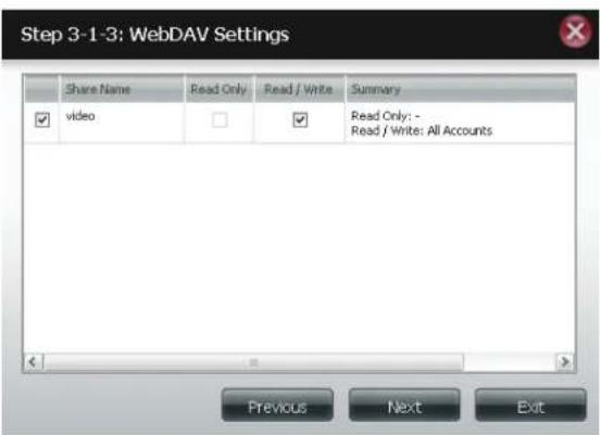
text_image
Step 3-1-3: WebDAV Settings Share Name Read Only Read / Write Summary video Read Only: - Read / Write: All Accounts Previous Next ExitStep 10 - Here a summary of the created shares will be displayed
Click Finish to save your settings.
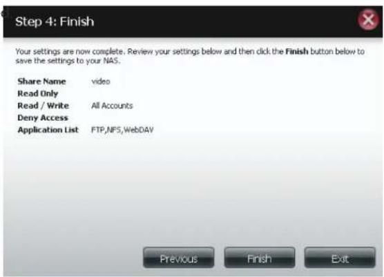
text_image
Step 4: Finish Your settings are now complete. Review your settings below and then click the Finish button below to save the settings to your NAS. Share Name video Read Only Read / Write All Accounts Deny Access Application List FTP,NFS,WebDAV Previous Finish ExitDeleting a Network Share
Select the Network Share you wish to delete. Your selection will turn red. Click Delete to remove the share.
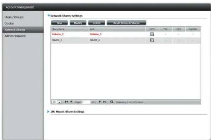
text_image
Account Management Users / Groups Quotes Network Shares Admin Password Network Shares Settings New Modify Delete Result Network Shares Share Share Web Volume_1 Volume_1 Volume_2 Volume_2 CPS FTR GPS WebGet ISO Mount Share SettingsA warning message will appear prompting you to verify if you wish to delete the Share. Click Yes to delete or No to Cancel.

text_image
Message Are you sure want to delete? Yes NoSection 4 - Configuration
The deleted Share will be removed from the Network Share List.
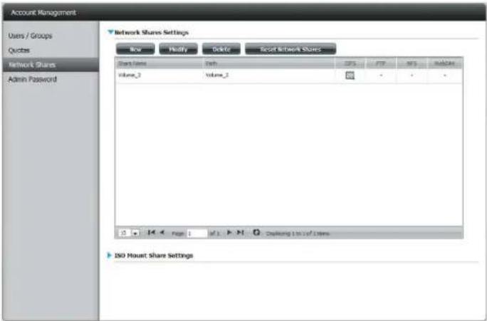
text_image
Account Management Users / Groups Quotes Network Shares Admin Password Network Shares Settings New Modify Delete Reset Network Shares Share Name Path CP5 FTP NF5 Database Volume_2 Volume_2 • • • ISO Mount Share SettingsResetting the Network Shares
Click the Reset Network Shares button.
Reset Network Shares
A warning message will prompt you to confirm your selection.
Click Yes to confirm or No to cancel.

text_image
Note: You are about to reset the Network Access List to default access rights. The access right is by default open (no password required) for all accounts.ISO Shares Setup Wizard
The following section will describe how to add a new ISO mount on the ShareCenter. To add an ISO Mount, click on the New button. An easy to configure wizard will launch.
Click Next to continue.

text_image
Welcome to ISO shares setup wizard The Wizard will guide you through the steps of steps. Begin by clicking on Next. 1. Select ISO file(s). 2. Shared Folder Access Rights. 3. Network Shares Settings. 4. Finish.Select the ISO file to mount.
Check the box to the left of the .iso file to select it and click Next to continue.
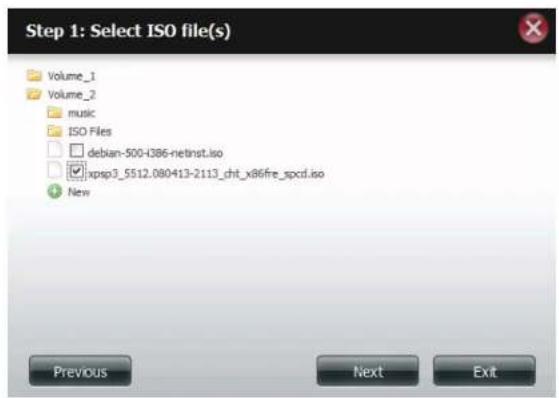
text_image
Step 1: Select ISO file(s) Volume_1 Volume_2 music ISO Files debian-500-H386-netinst.iso xpsp3_5512.080413-2113_cht_x86fre_spcd.iso New Previous Next ExitSection 4 - Configuration
Assign access privileges to this ISO Mount share.
- Select All Accounts to assign the ISO Mount share read/deny privileges to all users.
- Select Specific User/Group in order to assign read/deny privileges to individual users and groups.
Click Next to continue.

text_image
Step 2: Shared Folder Access Rights Select users to access the shared folder ○ All Accounts ○ Specific User/Group Previous Next ExitYou can assign Read Only or Deny Access privileges to the ISO Mount share here. Click on the appropriate radio button for the privileges you would like to assign.
Click Next to continue.
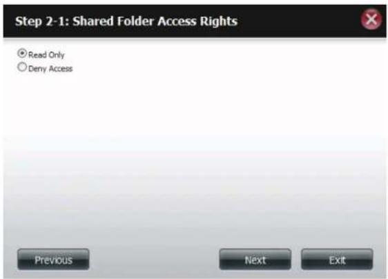
text_image
Step 2-1: Shared Folder Access Rights Read Only Deny Access Previous Next ExitSection 4 - Configuration
Add a comment that describes the ISO Mount Share.
Click Next to continue.
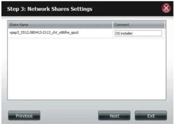
text_image
Step 3: Network Shares Settings Share Name Comment xpsp3_5512.080413-2113_cht_x86fire_spcd OS installer Previous Next ExitAssign more protocol privileges that a user can use to access this share. Options to choose from are FTP, NFS and WebDAV. CIFS and AFP are set as default.
• CIFS is short for Common Internet File System.
• AFP is short for Apple Filing Protocol.
- FTP is short for File Transfer Protocol
• NFS is short for Network File System.
- WebDAV is short for Web-based Distributed Authoring and Versioning.
Click Next to continue.
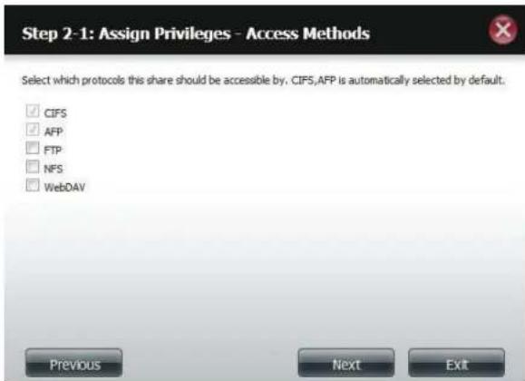
text_image
Step 2-1: Assign Privileges - Access Methods Select which protocols this share should be accessible by, CIFS,AFP is automatically selected by default. ✓ CIFS ✓ AFP ☐ FTP ☐ NFS ☐ WebDAV Previous Next ExitSection 4 - Configuration
A summary of the share will be displayed.
Click on the Finish button to accept the change and complete the wizard.

text_image
Step 4: Finish Your settings are now complete. Review your settings below and then click the Finish button below to save the settings to your NAS. Share Name xpsp3_5512.080413-2113_cht_x86fre_spcd Read Only All Accounts Deny Access - Application List - Previous Finish ExitThrough the D-Link Storage Utility, the ISO Mount Share can now be mapped to your computer as a normal network share.
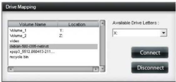
text_image
Drive Mapping Volume Name Location Volume_1 Y: Volume_2 Z: video debian-500-0385-netinst xpsp3_5512.080413-211... recycle.bin Available Drive Letters : X: Connect DisconnectCreating an ISO Image
The following section will describe how to create an ISO image from your NAS, export the data out to your PC.
Click Account Management > Network Shares > ISO Mount Share Settings.
Click on the Create ISO Image button at the bottom.
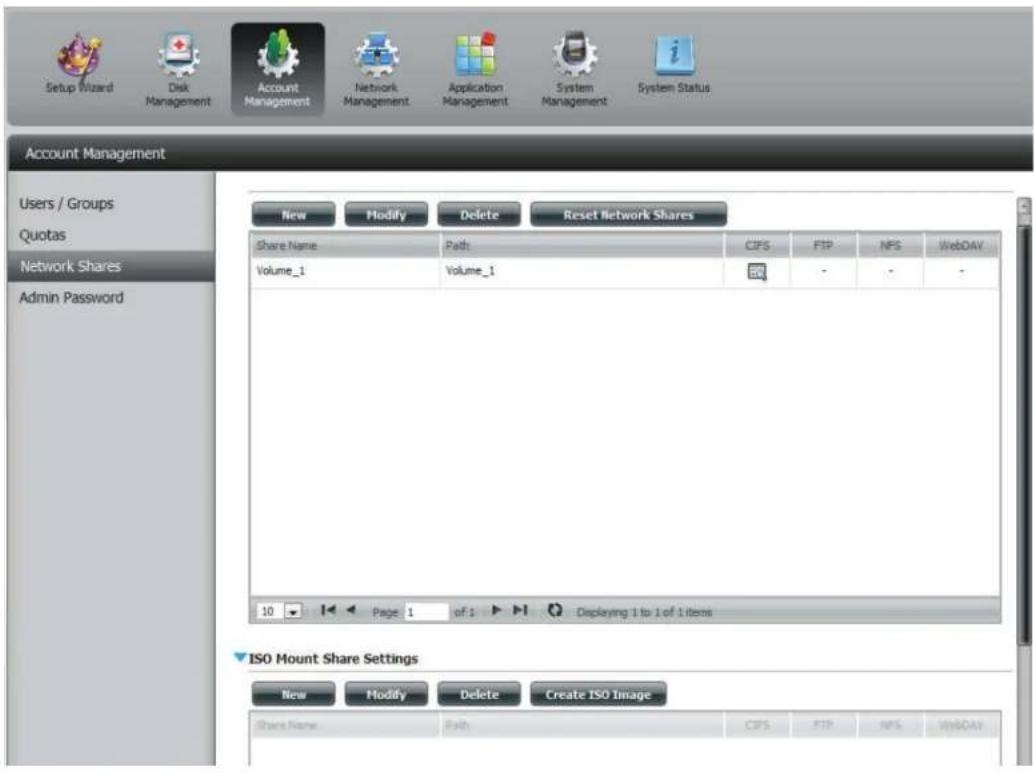
text_image
Setup Wizard Disk Management Account Management Network Management Application Management System Management System Status Account Management Users / Groups Quotas Network Shares Admin Password New Modify Delete Reset Network Shares Share Name Path CIFS FTP NPS WebDAV Volume_1 Volume_1 50 - - - 10 Page 1 of 1 Displaying 1 to 1 of 1 items ISO Mount Share Settings New Modify Delete Create ISO Image Share Name Path CIFS FTP NPS WebDAVISO image Creation Wizard
The ISO image wizard helps you create an ISO image on your ShareCenter.
Read the instructions for the ISO Image Creation Wizard and then click Next to continue.
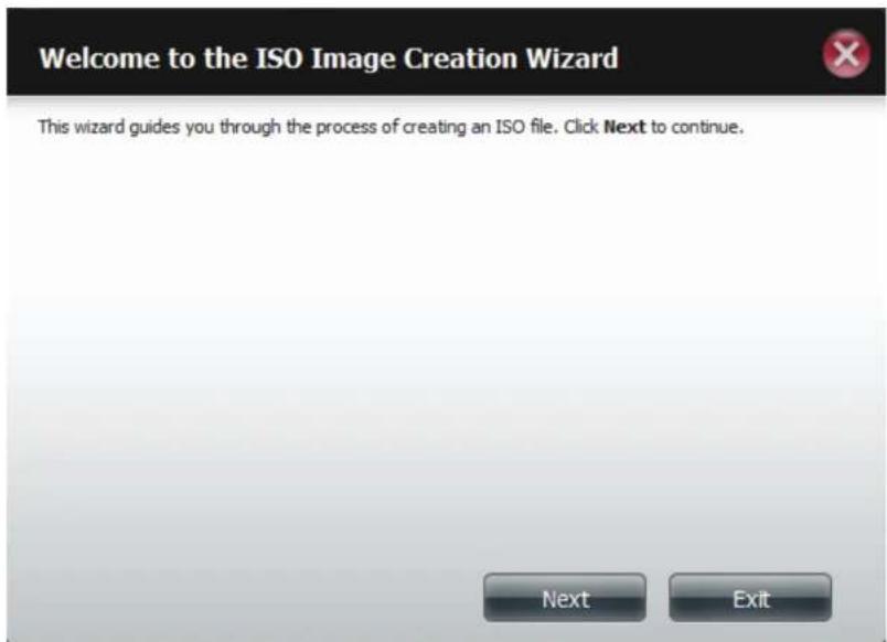
text_image
Welcome to the ISO Image Creation Wizard This wizard guides you through the process of creating an ISO file. Click Next to continue. Next ExitISO Name and File Path Settings
Select the Image Size.
There are three Image Size choices:
- CDROM (650MB/74MIN) - This creates an ISO file 650MB in size ready for burning onto a CDROM at a later stage.
- DVD5 (4.7GB) - This creates an ISO file 4.7GB in size ready for burning onto a single-layer DVD at a later stage.
- DVD9 (8.5GB) - This creates an ISO file 8.5GB in size ready for burning onto a double-layer DVD at a later stage.
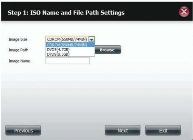
text_image
Step 1: ISO Name and File Path Settings Image Size CDROM(650MB/74MIN) CDROM(650MB/74MIN) Image Path DVD5(4.7GB) DVD9(8.5GB) Browse Image Name Previous Next ExitSelect the Image Path.
Click the Browse button to select the destination folder on your NAS. Click the Volume to save it there or click New to create a new directory.
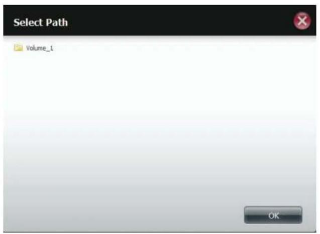
text_image
Select Path Volume_1 OK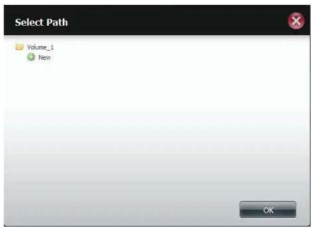
text_image
Select Path Volume_1 New OKEnter a name that resembles the ISO file you are writing. Click Next.

text_image
Step 1: ISO Name and File Path Settings Image Size CDROM(650MB/74MIN) Image Path Browse Image Name Previous Next ExitA warning message appears asking you to confirm your decision. Click Yes to continue or click No to cancel.
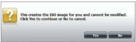
text_image
This creates the ISO image for you and cannot be modified. Click Yes to continue or No to cancel.ISO Tree Editing
On the left side of the ISO Tree Editing window you have the option to Overwrite a previous ISO file or Skip it. It also displays the main directory on your NAS. Select the file(s) and click the --> button to add the file(s) to the ISO image. On the right side of the window it displays the total available space of the ISO file and the used space of the ISO. At the bottom of the window it shows the path where the ISO file will be saved.
Click Next to continue.
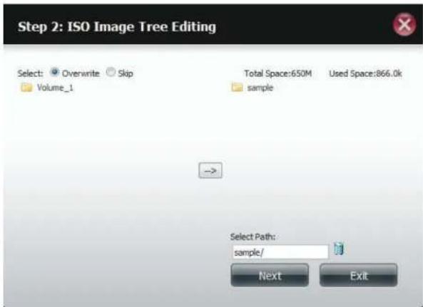
text_image
Step 2: ISO Image Tree Editing Select: Overwrite Skip Volume_1 Total Space:650M Used Space:866.0k sample → Select Path: sample/ Next ExitThe wizard will create the ISO image.
Click the Auto Mount checkbox if you want the ISO file to be mounted automatically.
Click Finish to close the wizard.
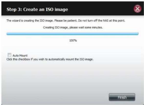
text_image
Step 3: Create an ISO image The wizard is creating the ISO image. Please be patient. Do not turn off the NAS at this point. Creating ISO image, please wait some minutes. 100% Auto Mount Click this checkbox if you wish to automatically mount the ISO image. FinishVerifying the ISO image
Open your Windows Explorer, click the Network icon, double-click your ShareCenter NAS. Double-click the volume you saved the ISO. Your ISO image should be there.
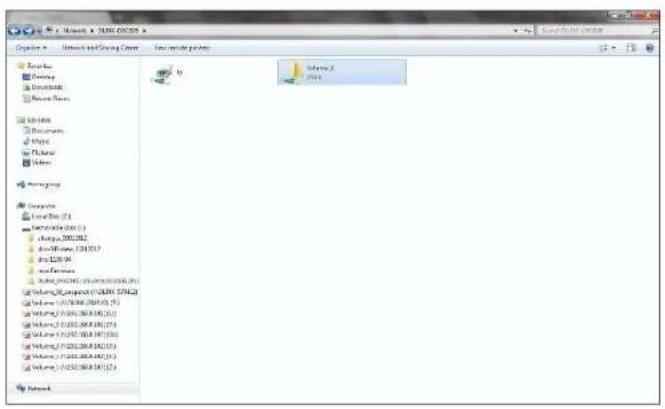
text_image
C:\Users\NTSEC\OCOS Operating - Internet and Working Server - Web-based project Sources: Discovery Download Resource Files Libraries Documents Music Photos Video Honey Group Corporate Local Data (1) Microsoft (0) Change 200.262 Auto-Commerce 534.757 Auto Web 99 Web Services Internet (0) 200.262 (0) 200.263 (0) Volume_0 (0) 200.263 (0) 200.264 (0) Volume_1 (0) 200.263 (0) 200.264 (0) Volume_2 (0) 200.263 (0) 200.264 (0) Volume_3 (0) 200.263 (0) 200.264 (0) Volume_4 (0) 200.263 (0) 200.264 (0) Volume_5 (0) 200.263 (0) 200.264 (0) Volume_6 (0) 200.263 (0) 200.264 (0) Volume_7 (0) 200.263 (0) 200.264 (0) Volume_8 (0) 200.263 (0) 200.264 (0) Volume_9 (0) 200.263 (0) 200.264 (0) Volume_10 (0) 200.263 (0) 200.264 (0) Volume_11 (0) 200.263 (0) 200.264 (0) Volume_12 (0) 200.263 (0) 200.264 (0) Volume_13 (0) 200.263 (0) 200.264 (0) Volume_14 (0) 200.263 (0) 200.264 (0) Volume_15 (0) 200.263 (0) 200.264 (0) Volume_16 (0) 200.263 (0) 200.264 (0) Volume_17 (0) 200.263 (0) 200.264 (0) Volume_18 (0) 200.263 (0) 200.264 (0) Volume_19 (0) 200.263 (0) 200.264 (0) Volume_20 (0) 200.263 (0) 200.264 (0) Volume_21 (0) 200.263 (0) 200.264 (0) Volume_22 (0) 200.263 (0) 200.264 (0) Volume_23 (0) 200.263 (0) 200.264 (0) Volume_24 (0) 200.263 (0) 200.264 (0) Volume_25 (0) 200.263 (0) 200.264 (0) Volume_26 (0) 200.263 (0) 200.264 (0) Volume_27 (0) 200.263 (0) 200.264 (0) Volume_28 (0) 200.263 (0) 200.264 (0) Volume_29 (0) 200.263 (0) 200.264 (0) Volume_3D (1) Volume_3E Volume_3F Volume_3G Volume_3H Volume_3I Volume_3J Volume_3K Volume_3L Volume_3M Volume_3N Volume_3O Volume_3P Volume_3Q Volume_3R Volume_3S Volume_3T Volume_3U Volume_3V Volume_3W Volume_3X Volume_3Y Volume_3Z Volume_3A Volume_3B Volume_3C Volume_3D Volume_3E Volume_3F Volume_3G Volume_3H Volume_3I Volume_3J Volume_3K Volume_3L Volume_3M Volume_3N Volume_3O Volume_3P Volume_3Q Volume_3R Volume_3S Volume_3T Volume_3U Volume_3V Volume_3W Volume_3X, Y/Y Y/Y
text_image
C:\Users\DATA\2018\Volume.1 Options - New Index Name: C:\Users\DATA\2018\Volume.1 Version: C:\Users\DATA\2018\Volume.1 Description: C:\Users\DATA\2018\Volume.1 Version: C:\Users\DATA\2018\Volume.1 Description: C:\Users\DATA\2018\Volume.1 Version: C:\Users\DATA\2018\Volume.1 Description: C:\Users\DATA\2018\Volume.1 Version: C:\Users\DATA\2018 Status: C:\Users\DATA\2018\Volume.1 Version: C:\Users\DATA\2018\Volume.1 Version: C:\Users\DATA\2018\Volume.1 Version: C:\Users\DATA\2018\Volume.1 Version: C:\Users\DATA\2018\Volume.1 Version: C:\Users\DATA\2018\Volume.1 Version: C:\Users\DATA\2018\Volume.1 Revision: Computer [ ] [ ] [ ] [ ] [ ] [ ] [ ] [ ] [ ] [ ] [ ] [ ] [ ] [ ] [ ] [ ] [ ] [ ] [ ] [ ] [ ] [ ] [ ] [ ] [ ] [ ] [ ] [ ] [ ] [ ] [ ] [ ] [ ] [ ] [ ] [ ] [ ] [ ] [ ] [ ] [ ] [ ] [ ] [ ] [ ] [ ] [ ] [ ] [ ] [ ] [ ]Admin Password
Changes to the administrator username and password can be made here.
The Administrator Settings allows you to change the Username and Password settings.
- Enter a new Username
- Type the original Password
- Enter a New Password
- Confirm the New Password

text_image
Account Management Users / Groups Quotas Network Shares Admin Password Administrator Settings User Name admin Password New Password Confirm Password Save Settings Don't Save SettingsClick Save Settings to accept the changes or Don't Save Settings to cancel changes.
Network Management
LAN Setup
Network Management controls and manages all issues referring to LAN settings. Even though your LAN settings were configured in the Setup Wizard, it can still be configured here. The ShareCenter will automatically configure both LAN cards as a single device. This is Ethernet Port Bonding and provides a more direct management of your LAN throughput. It also enables redundancy. If one of the ports fails, the other acts as backup. The network load is balanced across all links.
Go to Network Management and then LAN Setup.
Click Setup.
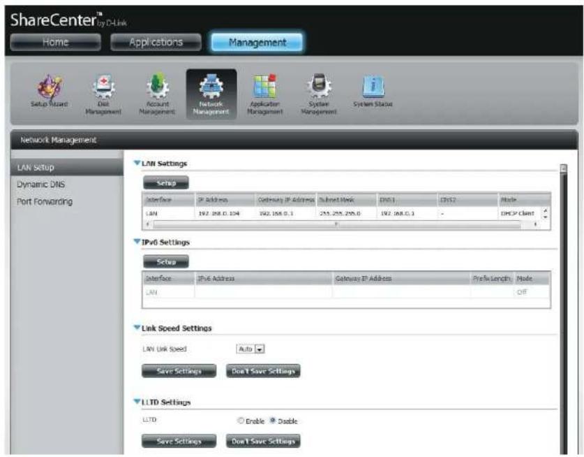
text_image
ShareCenter™ Home Applications Management Setup Wizard Diet Management Account Management Network Management Application Management System Management System Status Network Management LAN Setup Dynamic DNS Port Forwarding LAM Settings Setup Interface IP Address Gateway IP Address Subnet Work DNS1 DNS2 Mode LAN 192.188.0.104 192.188.0.1 253.255.295.0 192.188.0.1 - DNSP Client IPv6 Settings Setup Interface IPv6 Address Gateway IP Address Prefix Length Mode LAN Link Speed Settings LAN Link Speed Auto Save Settings Don't Save Settings LLTD Settings LLTD Enable Double Save Settings Don't Save SettingsSection 4 - Configuration
The LAN setup wizard gives you the option to configure two main settings - IP settings.
Click Next to continue.
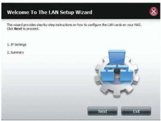
text_image
Welcome To The LAN Setup Wizard This wizard provides step-by-step instructions on how to configure the LAN cards on your NAS. Click Next to proceed. 1. IP Settings 2. Summary Next ExitThis step allows you to configure your LAN settings. Here you can choose between DHCP Client or Static IP. If you select Static IP, you will need to manually configure your own IP settings.
Click Next to continue.
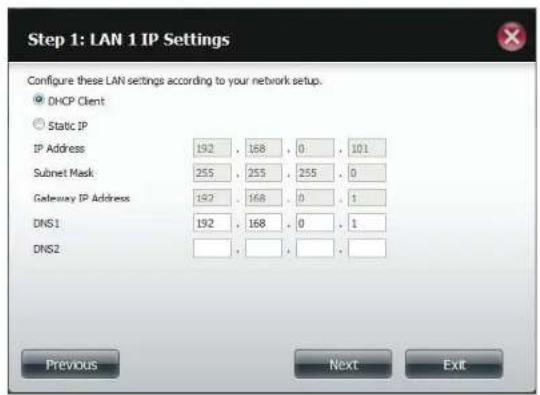
text_image
Step 1: LAN 1 IP Settings Configure these LAN settings according to your network setup. DHCP Client Static IP IP Address 192 168 0 101 Subnet Mask 255 255 255 0 Gateway IP Address 192 168 0 1 DNS1 192 168 0 1 DNS2 Previous Next ExitSection 4 - Configuration
A summary of what you just configured will be displayed.
Click Finish to exit the wizard.

text_image
Step 2: Summary This completes the wizard. Click Previous to review your settings. Click Finish to save the settings. Interface LAN Mode DHCP Client IP Address - Gateway IP Address - Subnet Mask - DNS1 192.168.0.1 DNS2 Previous Finish ExitIPv6 Settings
Go to Management > Network Management > LAN Setup > IPv6 Settings and click the Setup button. An IPv6 setup window will appear.

text_image
ShareCenter™ by D-Link Home Applications Management Setup Wizard Disk Management Account Management Network Management Application Management System Management System Status Network Management LAN Setup Dynamic DNS Port Forwarding LAN Settings Setup Interface IP Address Gateway IP Address Subnet Mask DNS1 DNS2 Mode LAN 0.0.0.0 192.168.0.1 255.255.255.0 192.168.0.1 - DHCP Client IPV6 Settings Setup Interface IPv6 Address Gateway IP Address Prefix Length Mode LAN Off Link Speed Settings LLTD SettingsIPv6 Setup
There are four connection modes to select from: Auto, DHCP, Static and Of.
Auto - Requests information specifically from an IPv6-enabled router and automatically configure your settings.
DHCP - Requests information from a DHCP server.
Static - Enter your own IP configuration
Of - Do not use IPv6
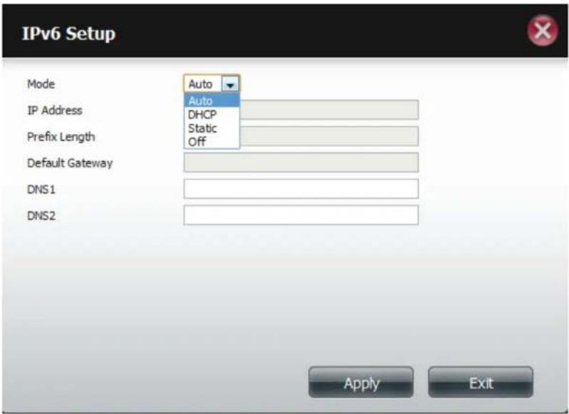
text_image
IPv6 Setup Mode Auto IP Address Auto DHCP Static Off Prefix Length Default Gateway DNS1 DNS2 Apply ExitSection 4 - Configuration
When configuring IPv6 with Static Mode, enter the IP address provided by your system administrator. The prefix length for an IPv6 subnet will always be 64; no more, no less. Enter the Default Gateway, and DNS settings. Click Apply when complete. The IPv6 Settings table will now display the settings in table format.
In order for the changes to take effect, you are prompted to re-login. Click OK and log in.
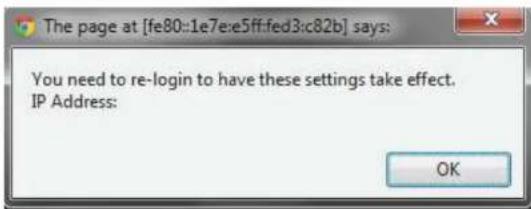
text_image
The page at [fe80:e1e7:e5ff:fed3:c82b] says: You need to re-login to have these settings take effect. IP Address: OK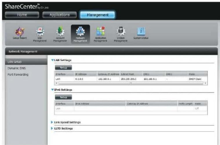
text_image
ShareCenter® Home Applications Management Setup Record Dial Management Account Management Network Management Application Management System Management System Status Network Management LAN Setup Dynamic DNS Port Forwarding LAB Settings Setup Interface: IP Address Gateway IP Address Subnet Mask: CNT1 CNT2 Home LAN 0.0.0 192.468.0.1 255.235.255.0 192.468.0.1 DHCP Client IPv6 Settings Setup Interface: IPv6 Address Customer IP Address Info: Length Mode: LAN OFF Link Speed Settings LLTD SettingsLink Speed and LLTD Settings
Link Speed: Select either Auto (Auto-Negotiate), 100Mbps, or 1000Mbps from the drop-down menu. Click the Save Settings button to save the new settings.
LLTD: The device supports LLTD (Link Layer Topology Discovery) and is used by the Network Map application that is included in Windows Vista® and Windows® 7.
Select to enable or disable LLTD.

text_image
ShareCenter™ by D-Link Home Applications Management Setup Wizard Dock Dool Management Account Management Network Management Application Management System Management System Setup Network Management LAN Setup Dynamic DNS Port Forwarding LAN Settings Setup Interface IP Address Gateway IP Address Subnet Mask DNS1 DNS7 Mode LAN 0.0.0.0 192.158.0.1 255.255.255.0 - - DnOP Client IP6 Settings Setup Interface IPv6 Address Gateway IP Address Prefix Length Mode LAN Off Link Speed Settings LAN Link Speed Auto Save Settings Don't Save Settings LLTD SettingsDDNS
The DDNS feature allows the user to host a server (Web, FTP, Game Server, etc...) using a domain name that you have purchased (www.whateveryournameis.com) with your dynamically assigned IP address. Most broadband Internet Service Providers assign dynamic (changing) IP addresses. Using a DDNS service provider, your friends can enter your domain name to connect to your server regardless of your IP address.
Go to Network Management and then Dynamic DNS.
DDNS: Select Enable or Disable.
Server Address: Select a DDNS Server from the combo box on the right hand-side, or type in the server address manually.
Host Name: Enter your DDNS host name.
Username or Key: Enter your DDNS username or key.
Password or Key: Enter your DDNS password or key.
Verify: Re-enter your password or key.
Status: Displays your DDNS status.
When the user clicks on the "Sign up for D-Link's Free DDNS service at www.DLinkDDNS.com link, the user will be re-directed to the D-Link DDNS page.
Here the user can create or modify a D-Link DDNS account to use in this configuration.
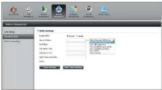
text_image
Network Management LAN Setup Dynamic Grid Host Networking DOWG Settings System ESC Tools Tools System ESC System ESC System ESC System ESC System ESC System ESC System ESC System ESC System ESC System ESC System ESC System ESC System ESC System ESC System ESC System ESC System ESC System ESC System ESC System ESC System ESC System ESC System ESC System ESC System ESC System ESC System ESC System ESC System ESC System ESC System ESC System ESC System ESC System ESC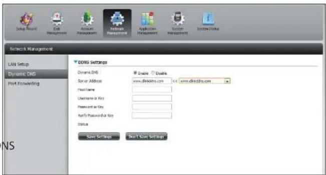
text_image
Network Management LAN Setup Dynamic DNS Port Forwarding DNS Settings Domain DNS Server Address www.dsnidtn.com Access Username or Key Password or Key Verify Password or Key Status Save Settings Done Save SettingsPort Forwarding
The DNS-320L supports UPnP port forwarding which configures port forwarding automatically on your UPnP-enabled router.
Note: You will need a UPnP router on your network.
Log in and click Network Management > Port Forwarding. Click Test to run a search.
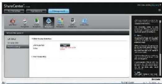
text_image
ShareCenter Add Existing Elements Add Existing Elements Add Existing Elements Add Existing Elements Add Existing Elements Add Existing Elements Add Existing Elements Add Existing Elements Add Existing Elements Add Existing Elements Add Existing Elements Add Existing Elements Add Existing Elements Add Existing Elements Add Existing Elements Add Existing Elements Add Existing Elements Add Existing Elements Add Existing Elements Add Existing Elements Add Existing Elements Add Existing Elements Add Existing Elements Add Existing Elements Add Existing Elements Add Existing Essentials Add Existing Essentials Add Existing Essentials Add Existing Essentials Add Existing Essentials Add Existing Essentials Add Existing Essentials Add Existing Essentials Add Existing Essentials Add Existing Essentials Add Existing Essentials Add Existing Essentials Add Existing Essentials Add Existing Essentials Add Existing Essentials Add Existing Essentials Add Existing Essentials Add Existing Essentials Add Existing Essentials Add Existing Essentials Add Existing Essentials Add Existing Essentials Add Existing Essentials Add Existing Essentials Add Existing Essentials Add Existing Elements Add Existing Elements Add Existing Elements Add Existing Elements Add Existing Elements Add Existing Elements Add Existing Elements Add Existing Elements Add Existing Elements Add Existing Elements Add Existing Elements Add Existing Elements Add Existing Elements Add Existing Elements Add Existing Elements Add Existing Elements Add Existing Elements Add Existing Elements Add Existing Elements Add Existing Elements Add Existing Elements Add Existing Elements Add Existing Elements Add Existing Elements Add Existing ElementThe DNS-320L is searching for a UPnP router. Do not turn off your NAS.
text_image
ShareControl ShareControl ShareControl ShareControl ShareControl ShareControl ShareControl ShareControl ShareControl ShareControl ShareControl ShareControl ShareControl ShareControl ShareControl ShareControl ShareControl ShareControl ShareControl ShareControl ShareControl ShareControl ShareControl ShareControl ShareControl ShareControl ShareControl ShareControl ShareControl ShareControl ShareControl ShareControl ShareControl ShareControl Stack Type: Top 100% Stack Type: Top 100% Stack Type: Bottom 100% Stack Type: Bottom 100% Stack Type: Bottom 100% Stack Type: Bottom 100% Stack Type: Bottom 100% Stack Type: Bottom 100% Stack Type: Bottom 100% Stack Type: Bottom 100% Stack Type: Bottom 100% Stack Type: Bottom 100% Stack Type: Bottom 100% Stack Type: BottomSection 4 - Configuration
A message will notify you that the wizard has found a UPnP router on the network.
Note that you have to enable UPnP on your router.

text_image
Found UPnP router on the network. YesClick the blue arrow next to port forwarding to reveal the Port Forwarding options.

text_image
Network Management LAD Setup Dynamic DNS Port Forwarding ShvP Raster Detection ShvP Raster Set Status Port Forwarding Path Finish Status ShvP Raster Detection ShvP Raster Set Status Port Forwarding ShvP Raster Detection ShvP Raster Set Status Port Forwarding ShvP Raster Detection ShvP Raster Set Status Port Forwarding ShvP Raster Detection ShvP Raster Set Status Port Forwarding ShvP Raster Detection ShvP Raster Set Status Port Forwarding ShvP Raster Detection ShvP Raster Set Status Port ForwardINGSection 4 - Configuration
Click Add.
The Port Forwarding wizard will start.
Click Next to continue.

text_image
ShareCenter® My Favorites Applications Management System Forward Link Management Account Management Network Management Application Management System Management System Status Network Management LAN Setup Dynamic DNS Port Forwarding UPGP Router Defectives UPGP Router Test Status Test UPGP Router Found on the network Port Forwarding Exit Family Deltr Software Options Remove Default/Help Finish/Help 14 Page 1 Get Help No Home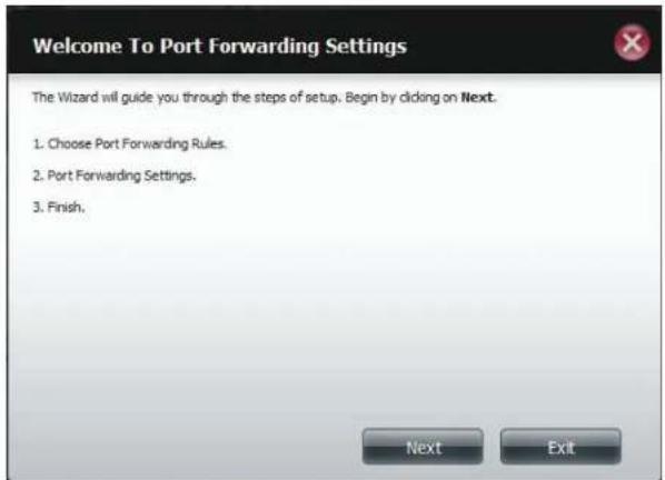
text_image
Welcome To Port Forwarding Settings The Wizard will guide you through the steps of setup. Begin by clicking on Next. 1. Choose Port Forwarding Rules. 2. Port Forwarding Settings. 3. Finish.Section 4 - Configuration
Select Select default service scan to select the port forwarding services from a list or select Custom a port forwarding service to manually configure your own settings.
Click Next to continue.
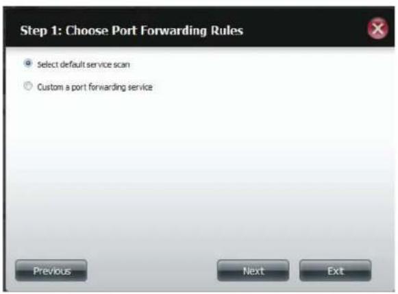
text_image
Step 1: Choose Port Forwarding Rules Select default service scan Custom a port forwarding service Previous Next ExtIf you select default service scan, choose the service(s) to be allowed for remote access from the Internet via your UPnP-enable router.
Note: You can select more than one port.
Click Previous to change the Port Forward Rule or Finish to configure the port forwarding on the UPnP router automatically.
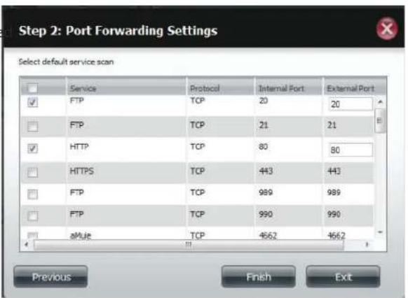
text_image
Step 2: Port Forwarding Settings Select default service scan Service Protocol Internal Port External Port FTP TCP 20 20 FTP TCP 21 21 HTTP TCP 80 80 HTTPS TCP 443 443 FTP TCP 989 989 FTP TCP 990 990 aMule TCP 4662 4662 Previous Finish ExitApplication Management
FTP server
The Application Management section allows you to configure many services for your DNS-320L. The server and service settings include: FTP server, UPnP AV server, iTunes server, AFP, and NFS services. Let's begin by looking at configuration options for the FTP server.
Max User: Set the maximum amount of users that can connect to the FTP server.
Idle Time: Set the amount of time a user can remain idle before being disconnected.
Port: Set the FTP port. Default is 21. If you are behind a router, you will need to forward the FTP port from the router to the device. Additional filtering and firewall settings may need to be modified on your router to allow FTP Acce to the device from the Internet. Once the port has been forwarded on the router, users from the Internet will access the FTP server through the WAN IP address of the router.
Passive Mode: In situations where the device is behind a firewall and unable to accept incoming TCP connections, passive mode must be used.
Client Language: Most standard FTP clients like Windows FTP, only support Western European code page when transferring files. Support has been added for non standard FTP clients that are capable of supporting these character sets.
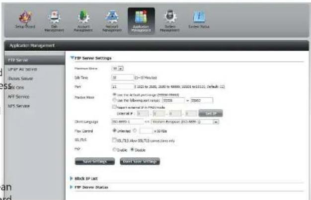
text_image
Application Management FTP Server UPSP AV Server Business Server Data Sets AFF Service NPS Service FTP Server Settings Platform Status: 16.20 Data Type: 58 (>=10 Mbps load) Port: 21 (3421 to 2000, 2000 to 48999, 20000 to 5310), Default: 12) Positive Mode: Use the default port range (20000-20000) Use the following port range: 10000 - 20000 Please enable IP to install a control IP: 0 - 1 - 2 - 3 - 4 - 5 - 6 - 7 - 8 - 9 - 10 - 11 - 12 - 13 - 14 - 15 - 16 - 17 - 18 - 19 - 20 - 21 - 22 - 23 - 24 - 25 - 26 - 27 - 28 - 29 - 30 - 31 - 32 - 33 - 34 - 35 - 36 - 37 - 38 - 39 - 40 - 41 - 42 - 43 - 44 - 45 - 46 - 47 - 48 - 49 - 50 - 51 - 52 - 53 - 54 - 55 - 56 - 57 - 58 - 59 - 60 - 61 - 62 - 63 - 64 - 65 - 66 - 67 - 68 - 69 - 70 - 71 - 72 - 73 - 74 - 75 - 76 - 77 - 78 - 79 - 80 - 81 - 82 - 83 - 84 - 85 - 86 - 87 - 88 - 89 - 90 - 91 - 92 - 93 - 94 - 95 - 96 - 97 - 98 - 99 - 100 Client Language: ISO-4000-1 = x: Minimum Version: ISO-4000-1 Flow Control: Unloaded: × x/Hz SQL/PLC: SQL/PLB Alive SQL/PLB switches only POP: Double Double Split Settings Event Slot Settings block IP List FTP Server StatusFlow Control: Allow you to limit the amount of bandwidth available for each user.
SSL/TLS: Here the user can enable the SSL/TLS connection only.
FXP: Enable or Disable File eXchange Protocol to transfer files from one FTP server to another.
Note: In order to use FXP (File Exchange Protocol) for server-to-server data transfer, make sure to change the port from 21 to some other port as listed in the Port section of the Web UI. Also, make sure to open the corresponding port on your router and forward that port from your router to the device.
Section 4 - Configuration
The window expands to include a Blocked IP list and a FTP Server Status report. Click the blue arrow to see the drop-down list.
Click New to block a specific IP address.
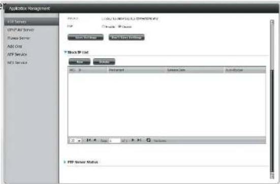
text_image
Application Management FTP Server USB AF Server FPGA Server ADC One FTP Service NFS Server FTP Server Status FTP Server Status FTP Server Status FTP Server Status FTP Server Status FTP Server Status FTP Server Status FTP Server Status FTP Server Status FTP Server Status FTP Server Status FTP Server Status FTP Server Status FTP Server Status FTP Server Status FTP Server Status FTP Server Status FTP Server Status FTP Server Status FTP Server Status FTP Server Status FTP Server Status FTP Server Status FTP Server Status FTP Server Status FTP Server StatesSelect IPv4 or IPv6 and then enter the IP address of a machine you wish to block. Select Permanent if you wish to block the IP address permanently or Temporary if you wish to set a time frame.
If you selected permanent, click Apply and continue.
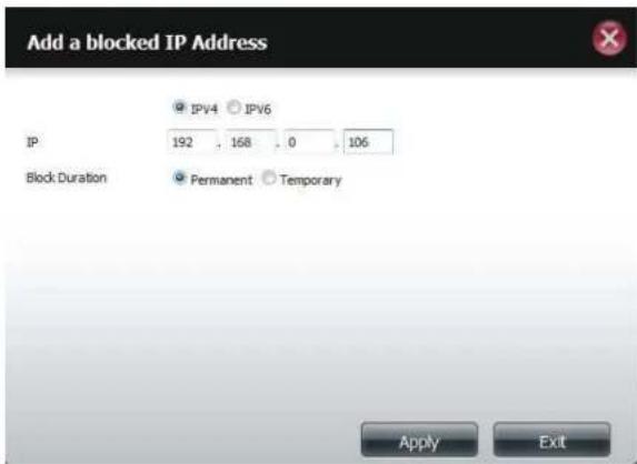
text_image
Add a blocked IP Address IPv4 IPv6 IP 192 . 168 . 0 . 106 Block Duration Permanent Temporary Apply ExitSection 4 - Configuration
If you selected Temporary, then select a time frame and click Apply to continue.

text_image
Add a blocked IP Address IP 192 . 168 . 0 . 106 Block Duration Permanent Temporary Block IP for 30 minutes 5 minutes 30 minutes 1 Hour 1 Day Apply ExtThe Blocked IP list will display the IP addresses you blocked.

text_image
FTP Server UHFP AV Server Theses Server Ask Chis NTS Server MT Server ASP.NET Management FTP ASP.NET ASP.NET Management ASP.NET Management ASP.NET Management ASP.NET Management ASP.NET Management ASP.NET Management ASP.NET Management ASP.NET Management ASP.NET Management ASP.NET Management ASP.NET Management ASP.NET Management ASP.NET Management ASP.NET Management ASP.NET Management ASP.NET Management ASP.NET Management ASP.NET Management ASP.NET Management ASP.NET Management ASP.NET Management ASP.NET Management ASP.NET Management ASP.NET Management ASP.NET Management ASP.NET MANAGEMENT ASP.NET MANAGEMENT ASP.NET MANAGEMENT ASP.NET MANAGEMENT ASP.NET MANAGEMENT ASP.NET MANAGEMENT ASP.NET MANAGEMENT ASP.NET MANAGEMENT ASP.NET MANAGEMENT ASP.NET MANAGEMENT ASP.NET MANAGEMENT ASP.NET MANAGEMENT ASP.NET MANAGEMENT ASP.NET MANAGEMENT ASP.NET MANAGEMENT ASP.NET MANAGEMENT ASP.NET MANAGEMENT ASP.NET MANAGEMENT ASP.NET MANAGEMENT ASP.NET MANAGEMENT ASP.NET MANAGEMENT ASP.NET MANAGEMENT ASP.NET MANAGEMENT ASP.NET MANAGEMENT ASP.NET MANAGEMENT ASP.NET granularity ASP.NET granularity ASP.NET granularity ASP.NET granularity ASP.NET granularity ASP.NET granularity ASP.NET granularity ASP.NET granularity ASP.NET granularity ASP.NET granularity ASP.NET granularity ASP.NET granularity ASP.NET granularity ASP.NET granularity ASP.NET granularity ASP.NET granularity ASP.NET granularity ASP.NET granularity ASP.NET granularity ASP.NET granularity ASP.NET granularity ASP.NET granularity ASP.NET granularity ASP.NET granularity ASP.NET granularity ASP.NET granular material processing softwareSection 4 - Configuration
Click the blue arrow next to FTP server status to reveal the FTP details.
The FTP server is stopped by default. Click Start FTP Server to run the process.

text_image
Application Management FTP Server ASP.NET AC 30.0015 Apache Server Add One API Service NIS Service FTP Server Status Server: 21 Provider Status: IP New Connection: Apache Data Time: IP Client Language: Apache Service 30/FLD After 30/FLD Service Status: IP Send FTP ServerUPnP AV Server
The ShareCenter features a UPnP AV Server. This server provides the ability to stream photos, music and videos to UPnP AV compatible network media players. If the server is enabled, the ShareCenter will be automatically detected by UPnP AV compatible media players on your local network. Click the Refresh All button to update all the shared files and folder lists after adding new files/folders.
Click Application Management, then UPnP AV Server.
Click the Enable radio button to enable the UPnP AV server.
Click Add to configure the UPnP AV share.
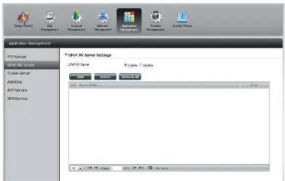
text_image
System Wizard Oil Management Hardware Management Application Management System Management System Setup Application Management FTP Server UHP AV Server Apache Server Add One ASP Service NPS Service UHP AV Server Settings UHP AV Server Apache Server Edit Modify Close AI 0.14.4.025 Edit: P.N. View: 0Select the volume you like to share and click Apply.
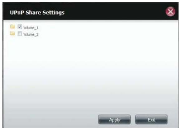
text_image
UPnP Share Settings Volume_1 Volume_2 Apply ExitSection 4 - Configuration
The NAS is building the media library.
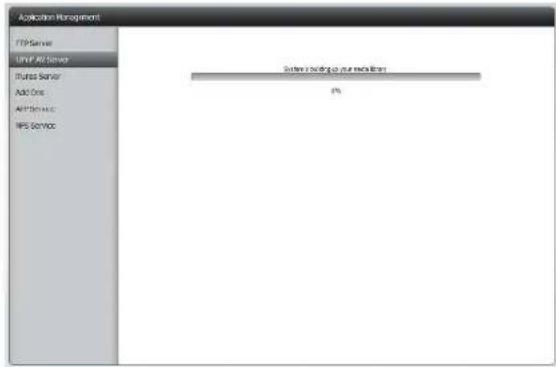
text_image
Application Management FTP Server WiFi AOS Server FPGA Server Add One AOS Service HPS Service System loading to your network 0%When the system has finished building the media library, a success message will appear.
Click Yes to continue.

text_image
Refreshed Successfully. YesSection 4 - Configuration
The selected volume will appear in the table under the UPnP AV server.

text_image
Setup Master Cell Management Account Management Network Management Application Management System Management System Data Application Management FTP Server VMF Air Server Fluxer Server Add Oits API Services MFS Service VMF Air Server Settings VMF Air Server Simple Double USB Required Sales 100% Options Help Help Page 1 Help > Help Options Helping Use User ListiTunes Server
The DNS-320L features an iTunes Server. This server provides the ability to share music and videos to computers on the local network running iTunes. If the server is enabled, the device will be automatically detected by the iTunes program and the music and videos contained in the specified directory will be available to stream over the network. Click the Refresh All button to update all the shared files and folder lists.
iTunes Server: Select to enable or disable the iTunes Server.
Folder: Specifies the folder or directory that will be shared by the iTunes server. Select root to share all files on all volumes, or click Browse to select a specific folders.
Password: Sets password for the iTunes server. (Optional)
MP3 Tag Codepage: Here the user can select the MP3 Tag Codepage used by this device. Currently the Codepage is set to Western European.
Auto Refresh: Here the user can select the Automatically Refresh time.

text_image
Setup Wizard Out Management AC/INS Management Network Management Application Management System Tools Application Management FTP Server XML TCP Server Windows Server Add Now TCP Server Access Services Windows Server Settings Basic Server C:\Users\Windows\Windows\Windows\Windows\Windows\Windows\Windows\Windows\Windows\Windows\Windows\Windows\Windows\Windows\Windows\Windows\Windows\Windows\Windows\Windows\Windows\Windows\Windows\Windows\Windows\Windows\Windows\Windows\Windows\Windows\Windows\Windows\Windows\Windows\Windows\Windows\Windows\Windows\Windows\Windows\Windows\Windows\Windows\Windows\Windows\Windows\Windows\Windows\Windows\Windows\Microsoft Windows File Edit View Insert Help Delete Add New Settings Save Settings Install New Settings RefreshAfter enabling the iTunes server on the ShareCenter, launch iTunes. In your iTunes utility, select the ShareCenter and enter the iTunes server password if required.
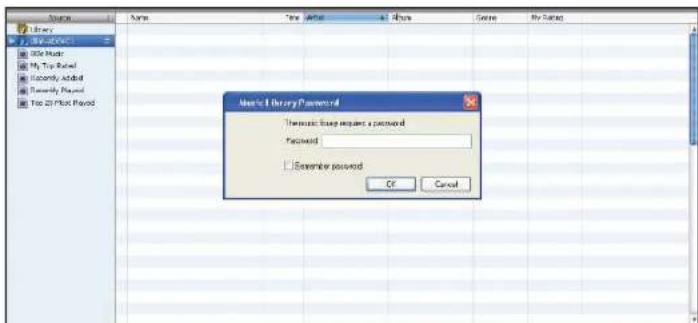
text_image
Microsoft Library Password Thousand Image request a password Password Examiner password OK CancelSelect the ShareCenter. When prompted, enter in the iTunes server password. Click OK.
| Source | Name | Tree Market | # | Runx | Gene | P‐Seq |
| 1 Library | Wright | 0.24 | Aerometh | Gol A Grp | Cock | |
| 2 Library | Wright The Rich | + 0.30 | Aerometh | Gol A Grp | Cock | |
| 3 500 Music | Wright A Key | 1.75 | Aerometh | Gol A Grp | Cock | |
| 4 500 Top Board | Wright | + 0.75 | Aerometh | Gol A Grp | Cock | |
| 5 Recently Added | Wright In The Headie | + 0.75 | Aerometh | Gol A Grp | Cock | |
| 6 Recently Added | Wright | + 0.48 | Aerometh | Gol A Grp | Cock | |
| 7 Top 25 Post Place | Wright On Down | + 0.39 | Aerometh | Gol A Grp | Cock | |
| Wright Up And Save | + 0.35 | Aerometh | Gol A Grp | Cock | ||
| Wright! | + 0.38 | Aerometh | Gol A Grp | Cock | ||
| Wright Into E | + 0.39 | Aerometh | Gol A Grp | Cock | ||
| Wright | + 0.39 | Aerometh | Gol A Grp | Cock | ||
| Wright Up | + 1.32 | Aerometh | Gol A Grp | Cock | ||
| Wright Into | + 1.35 | Aerometh | Gol A Grp | Cock | ||
| Wright Into | + 2.17 | Aerometh | Gol A Grp | |||
| Wright Play | + 3.39 | Coplay | A(Ash of food T... ) Cock | |||
| Wright In Race | + 3.49 | Coplay | A(Ash of food T... ) Cock | |||
| Wright Re Into Upon Your Face | + 4.77 | Coplay | A(Ash of food T... ) Cock | |||
| The Journal | + 3.29 | Coplay | A(Ash of food T... ) Cock | |||
| World's | + 0.27 | Coplay | A(Ash of food T... ) Cock | |||
| World's Play | + 0.27 | Coplay | A(Ash of food T... ) Cock | |||
| Green Cars | + 3.49 | Coplay | A(Ash of food T... ) Cock | |||
| Writing Sign | + 3.51 | C-play | A(Ash of food T... ) Cock | |||
| Writing Shaper | + 3.58 | C-play | A(Ash of food T... ) Cock | |||
| A(Ash of food T... ) (In the Head) | + 3.51 | C-play | A(Ash of food T... ) Cock | |||
| Andringa Play | + 5.39 | C-play | A(Ash of food T... ) Cock | |||
| Dress | + 4.22 E.M. R. R. R. R. R. R. R. R. R. R. R. R. R. R. R. R. R. R. R. R. R. R. R. R. R. R. R. R. R. R. R. R. R. R. R. R. R. R. R. R. R. R. R. R. R. R. R. R. R. R. P. P. P. P. P. P. P. P. P. P. P. P. P. P. P. P. P. P. P. P. P. P. P. P. P. P. P. P. P. P. P. P. P. P. P. P. P. P. P. |
Media stored on the ShareCenter will then be available for use in iTunes.
AFP Service
The ShareCenter supports Apple Filing Service for connectivity with Mac OS ^® based computers. If you need to use AFP service enable it here otherwise leave it disabled to reduce CPU resource overhead.
Click Application Management > AFP Service.
Click the Enable radio button to turn AFP service on.
Click Save Settings.

text_image
ASP Service Settings ASP Service - # Delete ▼ Delete [Enter adding hardware bits of desktop icons] Copy SettingsNFS Service
The ShareCenter supports Network File System (NFS) service. To enable this multi-platform file system on your ShareCenter enable it here. Otherwise disable the option to prevent unnecessary CPU overhead.
Click Application Management > NFS Service.
Click the Enable radio button to turn NFS service on.
Click Save Settings.
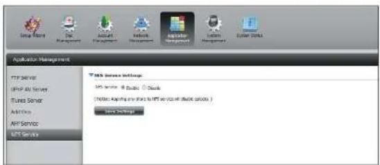
text_image
Application Management FTP server Group Data Server iTunes Server Add/Remove API Service MCS Server Web Service Settings MCS server: 8 Cloud 9 Cloud [Notes: Applying any share to MCS server you will choose options ] Home SettingsSystem Management
Language
The language packs help users customize the DNS-320L to their specific region. Download your language pack from the D-Link website or the CD and follow the instructions below. When you disable the language pack, the GUI will return to English.
Click System Management and then Language to install a new language.
Click on Browse to search for the specific language pack you want to install. After selecting the language pack, click Apply to install the language pack.

text_image
ShareCenter Name Applications Management System Management Language Form and Style Groups System Integration Power Management Settings Log Power Management USB Devices Language Form and Style Groups System Integration Power Management Settings Log Power Management USB Devices Language Form and Style Groups System Integration Power Management Settings Log Power Management USB Devices Language Form and Style Groups System Integration Power Management Settings Log Power Management USB Devices Language Form and Style Groups System Integration Power Management Settings Log Power Management USB Devices Language Format: System10000000000000000000000000000000000000000000000000000000000000000000000000000000000000000000000000000If you have not selected a language package, a message will prompt you to locate one.
Click Yes to continue.

text_image
Please select a package. YesTime and Date
The Time and Date configuration option allows you to configure, update, and maintain the correct time and date on the internal system clock. In this section you can set the time zone that you are in, and set the NTP (Network Time Protocol) Server in order to periodically update your system time from the NTP Server. You can also sync the time and date of your computer as the system time.
Click System Management, then Time and Date. Select the Set Time from My Computer button if you want to use the time and date of your computer. When a confirmation message appears, click Yes to continue.

text_image
Start Name End Management Account Management Network Management Application Management System Administration System Default Language Time and Date Device System Settings Power Management Applications Help Hardware Upgrade USB Devices System Time Settings Current Time: 00:36:54/99:00:00 Time Line: OFF Guidance, None/No Set the Time And Time Currently Date: 01/01/2020 Time: 12:00:00:00 Set Time: None My Computer Save Settings Time Date Time Line: OFF Guidance, None/No Save Settings FTP Server FTP Server Add Select FTP Server Save SettingsSelect your time zone from the drop-down menu. Click Save Settings.
You can also select a NTP server from the drop-down menu to sync the time and date with an online server. Then click Save Settings.
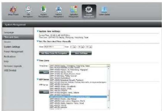
text_image
System Management Language Time and Date Design System Settings Power Management Recommendation Logy Formwork Upgrade USE Devices System Line Settings Control Time: 00:25.1.4P 00:07:2013 Time Line: 00:16.0.0.0, Changing, Running, Type Set the Data And Data Manuals Date: 00:16:2013 Set Time From My Computer Save Settings Time Zone Time Series: CPT-000300000, Deninging, Running, Type CPT-000300000, Deninging, Running, Type CPT-000300000, Deninging, Running, Type CPT-000300000, Deninging, Running, Type CPT-000300000, Deninging, Running, Type CPT-000300000, Deninging, CPT-000300000, Deninging, Running, CPT-000300000, Deninging, Running, CPT-000300000, Deninging, Running, CPT-000300000, Deninging, Running, CPT-000300000, Deninging, Running, CPT-000300000, Deninging, Running, CPT-16.1.1.1.1.1.1.1.1.1.1.1.1.1.1.1.1.1.1.1.1.1.1.1.1.1.1.1.1.1.1.1.1.1.1.1.1.1.1.1.1.1.1.1.1.1.1.1.1.1.1.2.1.2.2.2.2.2.2.2.2.2.2.2.2.2.2.2.2.2.2.2.2.2.2.2.2.2.2.2.2.2.2.2.2.2.2.2.2.2.2.2.2.2.2.2.2.2.2.2.2.2.2.3.Device
The device settings page allows you to assign a workgroup, name and description to the device. You can access this device by typing the host name in the URL section of your web browser. For example: http://dlink-d10001.
Workgroup:
Enter your Workgroup name here. The workgroup name should be the same as the computers on the network. Devices using the same workgroup will have additional file sharing methods available.
Name:
Enter your device name here. This name is what the device will appear as on the network. By default, the device name is dlink-xxxxxx, where xxxxxx is the last six digits of the MAC address.
Description:
Assign a device description to the device.
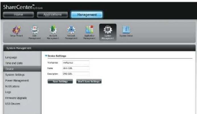
text_image
ShareCenter™ by D link Home Applications Management Setup Wizard Edit Management Account Management Network Management Application Management System Management System Status System Management Language Time and Date Device System Settings Power Management Notifications Logs Hardware Upgrade USB Devices Device Settings Workshop : xrefitusa Name : dru-120L Description : DRI-120L Save Settings Don't Save SettingsSystem Settings
System Settings provides features to control your DNS-320L. Users can restart the NAS, restore the system to its original state, set idle times, shutdown the system, configure settings, and configure system temperature settings.
Restart: Click to reboot the DNS-320L.
Default: Click to restore the device back to the factory default settings. All previous settings that have been configured will be erased.
Shutdown: Click to turn off the DNS-320L.
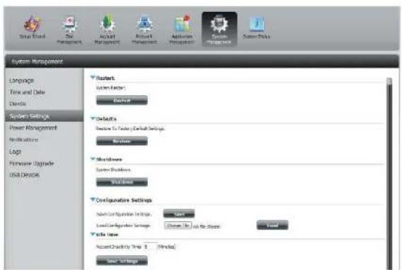
text_image
System Management Language Time and Date Details System Settings Power Management Modulation Log1 Hardware Upgrade USB Device Starts System Settings End Defaults Service to Server/Default Settings Reverse Sharedowns System Buildings Welcome Configurations Settings Service Configuration Settings Save... Load Configuration Settings Change To Use to Store Load Trade Time Account Design Time 0 (Minutes) Save SettingsConfiguration Click on the Save button to save the current Settings: configuration settings to a file on your computer. If at a later time you need to reload this configuration after a system reset, browse to the file and click Load.
Idle Time: Enter the time (in minutes) that the administrator and users will be allowed to remain idle while accessing the web UI.
System Temperature Threshold: Here you can configure the system temperature threshold value. This value can be set in Fahrenheit or Celsius. The device will automatically shutdown when it reaches the temperature set here.
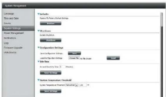
text_image
System Management Language Time and Date Source System Setup Power Management Instructions Log Firewall Upgrade Buildings Defaults Features To Founding Default Settings Balance Shareholders System Instances Workload Configuration Settings Switch Configuration Options Load Configuration Settings Close Pin to the Player User File Time Accrual Frequency Time: 0 Mbps Save Settings System Temperature Threshold System Temperature Trained: -45 °C Save SettingsPower Management
The device Power Management feature allows you to configure the drives to shut down while power remains constant to the device. The drives will power up again when data is accessed.
HDD Click Enable or Disable.
Hibernation:
Turn Off Hard Set the amount of idle time before the drives go into Drives: hibernation.
Power Recover: Click Enable or Disable. The Power Recovery feature will automatically restart your device from a previously unexpected shutdown due to a power failure.

text_image
Setup Board System Management Active Active Management Network Management System Management System Setup System Management Language Time and Date Device System Settings Power Management Notifications Logi Hardware Upgrade USB Devices Hard Drive Hibernation Settings +DD Hibernator @ enable Enable Turn Off Hard Drives / After Trainers ▼ Save Settings Power Recovery Settings Power Recovery Enable Enable Save Settings Fan Control Settings Type Auto (Off/Low/High) User Settings Power On/Off scheduling Settings OLED Display SettingsYou can control the speed of the fan using three different settings and you can power off the device at scheduled times for each day of the week.
Fan Control: The speed of the fan can be controlled from this section.
If you select Auto mode, the speed of the fan will change (Off/Low/High) depending on the internal temperature of the enclosure.
Power Off Click Enable to turn on this function. Scheduling:
Enable or disable the power off days using the check box and configure the time for each day that the power off will occur.
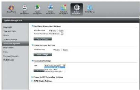
text_image
Start Time Allocation Settings +30 ms/40 Speed 120000000000000000000000000000000000000000000000000000000000000000000000000000000000000000 System Management Language Time and Date Device System Settings Power Management Instructions Logic Firmware Options USB Devices Power Access Settings Power Recovery Speed Settings Power Control Settings Type: Speed (5.7x1.8x1.8x1.8x1.8x1.8x1.8x1.8x1.8x1.8x1.8x1.8x1.8x1.8x1.8x1.8x1.8x1.8x1.8x1.8x1.8x1.8x1.8x1.8x1.8x1.8x1.6 Power On/Off Scheduling Settings OLED Display Settings
text_image
System Management Language Time and Date Device System Settings Power Management Instructions Loop Forward Upgrade USB Devices Power Recovery Settings Panel Summary Delete Delete Power Settings Power Control Settings Type: Active On/OFF (OK) Save Settings Power On/Off Delete Delete Load Co Load Co Load Co Load Co Load Co Load Co Load Co Load Co Load Co Load Co Load Co Load Co Load Co Load Co Load Co Load Co Load Co Load Co Load Co Load Co Load Co Load Co Load Co Load Co Load Co Load Co Load Co Load Co Load Co Load Co Load Co Load Co Load Co Load CoNotifications Email Settings
Login Method: Select either Account or Anonymous. Choosing Anonymous does not require a User Name or Password.
Username: Enter the appropriate user name for your e-mail account.
Password: Enter the appropriate password for your e-mail account.
Port: Enter the SMTP port number used here.
SMTP Server: Enter the IP address or domain name of your outgoing main server. If you are unsure of this value, contact your e-mail provider.
Sender E-mail: Enter the "from" e-mail address (e.g. alerts@share.com). This field does not require a valid e-mail address. However, if your e-mail client is filtering spam, make sure you allow this address to be received.
Receiver E-mail: Enter the e-mail address you want to send the alerts to. This address must correspond with the SMTP server configured above.
Secure Select STARTTLS or SSL from the drop-down menu if it is Connection: required by your SMTP server, or select NONE.
Test E-Mail: Click the Test E-Maibbutton to send a test alert and confirm your settings are correct.
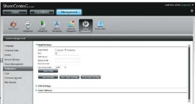
text_image
ShareCenter® Home Application Management System Management Language Time and Date Device Services Settings Host Properties Applications Logic Promote Upgrade Skill Devices Local Settings Local Field Account - Impress Port: 20 Data Set Resource Set Water Connection - DHP Total Field Save Settings Open Save Settings Open User Settings SHS Settings Forest Settings Welcome, Other [log.dwg]SMS Settings
The same alerts of system conditions that can be sent to an email box can also be sent to a mobile phone or by SMS text messages. You need to have an agreement with a SMS service gateway that the device can then be configured to send the alerts to. The service provider then sends the received alerts to the configured mobiles as text messages.
Enable SMS Check this box to enable SMS alerts to be sent to Notifications: your mobile phone.
SMS Service Provider: Select from the drop-down list your SMS service provider you would like to use (these are added with the Add button)
Add button: Click on the Add button and enter the information into the appropriate fields that your provider has given you to use for the configuration.
Delete button: Remove the selected Service Provider from the configuration.
URL: The specific service provider URL provided and added in the Add procedure.
Replace space If required by your service provider enter a character with: character that will be used for the space.
Phone Number 1: Automatically populated from the Add button function.
Phone Number 2: Enter a second mobile telephone number. Verify that the number input is according to the configuration instructions from your Mobile Service Provider.
Test SMS button: Click this button to send a test message to your mobile phone to verify the settings are correct and the API URL is functioning with your provider.

text_image
System Management Language Time and Date Device System Settings Power Management Vccrmatics Logs Framework Librics Use Devices SHP Server mail company.com Sensor Email id-4 company.com Business Email yjg@npea.com Test Set List Save Settings Done Save Settings Store Save Settings SMS Settings Create new software 3ds service provider Add Delete Java new the required special character from your service provider Use default Pure server 1 Pure server 2 Test Site Date: 10:00:00:00:00:00:00:00:00:00:00:00:00:00:00:00:00:00:00:00:00:00:00:00:00:00:00:00:00:00:00:00:00:00:01 Save Settings Done Save SettingsAdding an SMS Service Provider
Once you have a SMS Service provide you with a HTTP API URL, enter it into the Add SMS Service Provider wizard. Enter the URL in the first window with an appropriate Provider Name. In the next window select the appropriate HTTP API URL parameter types definitions from the drop-down menus next to the parsed fields of the URL.
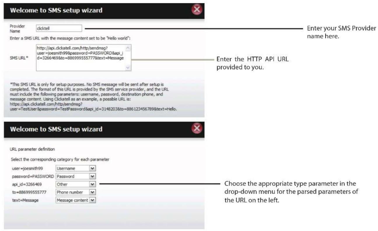
text_image
Welcome to SMS setup wizard Provider Name clicktell Enter a SMS URL with the message content set to be "Hello world": SMS URL * http://api.clickatell.com/http/sendmsg? user=joesmith99&password=PASSWORD&api_id=3266469&to=886999555777&text=Message Enter your SMS Provider name here. Enter the HTTP API URL provided to you. *This SMS URL is only for setup purposes. No SMS message will be sent after setup is completed. The format of this URL is provided by the SMS service provider, and the URL must include the following parameters: username, password, destination phone, and message content. Using Clickatell as an example, a possible URL is: https://api.clickatell.com/http/sendmsg? user=TestUser&password=TestPassword&api_id=3148203&to=886123456789&text=Hello. Welcome to SMS setup wizard URL parameter definition Select the corresponding category for each parameter user=joesmith99 Username password=PASSWORD Password api_id=3266469 Other to=886999555777 Phone number text=Message Message content Choose the appropriate type parameter in the drop-down menu for the parsed parameters of the URL on the left.Event Settings
You can limit which events are sent as alerts to the Email or SMS settings by checking the events here.
Event Settings: Select the information you want e-mailed to the above address or sent over SMS messages to the above mobile number. The items checked will be sent when necessary.
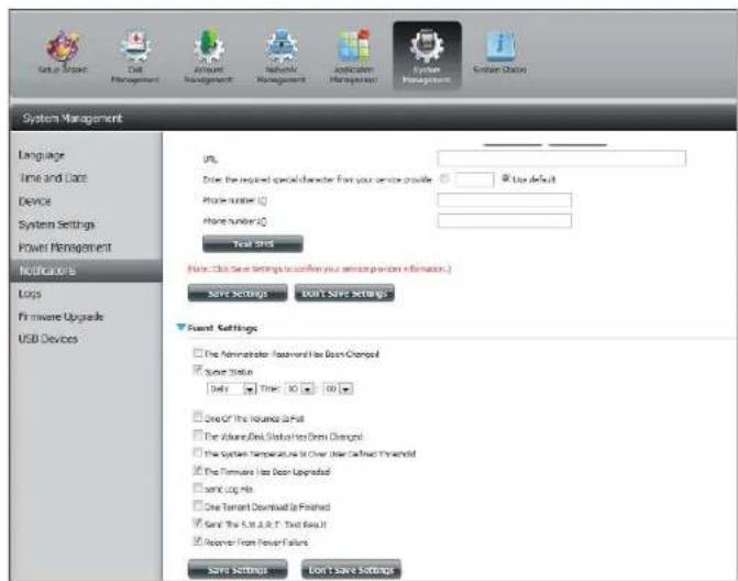
text_image
System Management Language Time and Date Device System Settings Power Management Notification Laps Firmware Upgrade USB Devices URL: Drive the required special character from your service provider Use default Phone number: Phone number: Test Shot Note: Click Save Settings to confirm your existing portion information.) Save Settings Don't Save Settings Event Settings The Administrator Treatment has Been Changed Save Status Daily Time 10 10 One Of the Location to Put The Advanced Disk Status has Been Changed The System Temperature is over time called Threshold The Maintenance has Been Upgraded save Log No One Tenant Download is Finished Save The S.E. & A.T. Text Result Receive From Fewer Failure Save Settings Don't Save SettingsLogs
Within the Logs menu you can setup your ShareCenter to receive Log Events from other ShareCenters or send the ShareCenter's log events to another ShareCenter or SysLog server. You can also view the NAS system logs and the FTP logs here.
Enable Syslog: Click to activate the Syslog server functionality of your device to be able to receive logs from other ShareCenters.
Syslog Server IP: Enter the IP address of an external Syslog server that you wish to send the logs of this device to.
Clear Log: Click Clear Log to delete all the existing logs.
Backup Log: Click Backup Log to save the existing logs to a text file on your computer.

text_image
System Management Language Time and Date Device System Settings Power Management Notifications Log Primerize Upgrade Ship Unit Devices Server Settings Enable Setup Interface IP 325 W4 8 170 Server Settings Enable Server Settings Large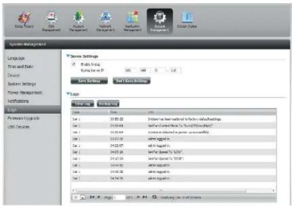
text_image
System Management Language Time and Data Device System Settings Forma Management Instructions Log Promote Aggregate USB Devices Server Settings Enable Link OK Cancel Save Settings Set/End Settings Login File Name 1er 2 3er 3 4er 3 5er 2 6er 2 7er 2 8er 2 9er 2 10er 2 11er 2 12er 2 13er 2 14er 2 15er 2 16er 2 17er 2 18er 2 19er 2 20er 2 21er 2 22er 2 23er 2 24er 2 25er 2 26er 2 27er 2 28er 2 29er 2 30er 2 31er 2 32er 2 33er 2 34er 2 35er 2 36er 2 37er 2 38er 2 39er 2 40er 2 41er 2 42er 2 43er 2 44er 2 45er 2 46er 2 47er 2 48er 2 49er 2 50er 2 51er 2 52er 2 53er 2 54er 2 55er 2 56er 2 57er 2 58er 2 59er 2 60er 2 61er 2 62er 2 63er 2 64er 2 65er 2 66er 2 67er 2 68er 2 69er 2 70er 2 71er 2 72er 2 73er 2 74er 2 75er 2 76er 2 77er 2 78er 2 79er 2 80er 2 81er 2 82er 2 83er 2 84er 2 85er 2 86er 2 87er 2 88er 2 89er 2 90er 2 91er 2 92er 2 93er 2 94er 2 95er 2 96er 2 97er 2 98er 2 99er 2Firmware Upgrade
The Firmware Upgrade Page makes it simple to check for and upload new firmware releases to the device. This section provides a link to check for new firmware on the D-Link support website. If new firmware is available, download the file to your local computer.
Current Firmware Displays the current firmware version on your Version: ShareCenter® device.
Firmware Date: Displays the date of when the firmware was created.
Firmware Upload: When upgrading the firmware, click Browse to select the new firmware file on your local computer and then click Apply to begin the firmware upgrade process.
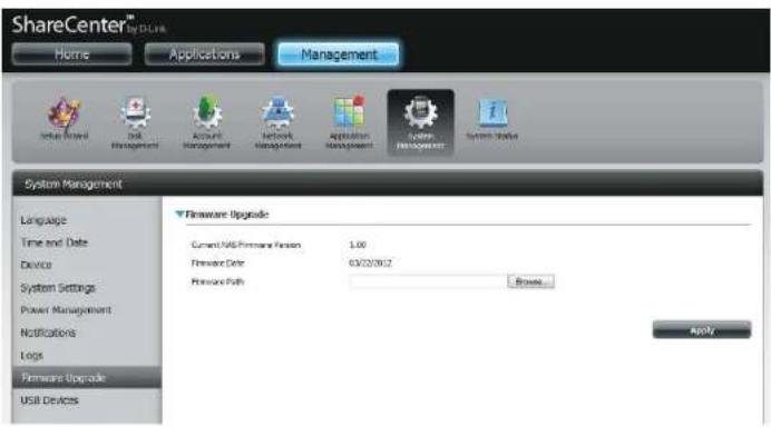
text_image
ShareCenter® by CLK Home Applications Management System Interface Disk Management Account Management Network Management Application Management System Manager System Management Language Time and Date Device System Settings Power Management Notifications Logs Firmware Upgrade USB Devices Firmware Upgrade Current USB Firmware Version 1.00 Firmware Date 03/20/08/2 Firmware Path Browse... ApplyUSB Devices UPS Settings
Network UPS is a system management feature that uses a local UPS to protect your NAS from an abnormal shutdown due to a power failure.
To enable Network UPS to your NAS (Network Slave Mode):
- Click to enable the Network UPS.
- Enter an IP address of the Network UPS Master.
- Click Save Settings to receive the critical power status from the network UPS master.
The UPS Status will display the current status of your UPS.
Note: Make sure that the ShareCenter is in the same network as the network UPS master.
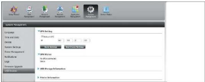
text_image
System Management Language Time and Date Device System Settings Power Management Instructions Logic Hardware Upgrade USB Device USB Setting If Network USD IP 107 148 17 129 Save Settings Not Save Settings USB Status No PS connected. Data USB Storage Information Printer InformationIf a UPS device is connected to the USB port on your NAS, you can select either Stand-Alone or Master mode. If you select Master mode, you will have to enter the IP address(es) of the network UPS slaves to notify them in the event of a power failure. For more details, refer to the UPS Connectivity section.
USB Storage Information
Click the blue arrow to reveal the USB storage Information.
It displays information on the manufacturer, product name, and size (capacity).
Click the Unmount button to eject the USB device.
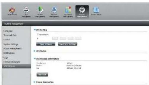
text_image
Submit Management Language Form and Data Device System Settings Model Management Instructions Gain Performance Update Instructions Edit Settings Size Settings Text Size Settings Size Status Size Settings Information Description Product Size Power Generation Power10000000000000000000000000000000000000000000000000000000000000000000000000000000000000000000000000000 Default Power ElementsPrinter Information
Click the blue arrow to reveal Printer Information.
It displays information on the manufacturer, product type, and connection details.
Click Clear Print Queue(s) to remove all active print jobs.
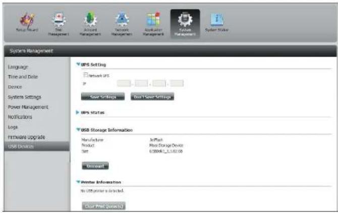
text_image
System Management Language Time and Date Device System Settings Power Management Notifications Logs Hardware Upgrade USB Devices UPS Setting Network IPS Save Settings On 1 Save Settings UPS Status USB Storage Information Manufacturer: Product: Size: Jetmail: New Storage Device 0.0004E_C_3.382.00 Discount Printer Information No USB printer is directed. Clear Print (please)System Status
System Info
The System Status information screen provides information on the DNS-320L. System Info provides information on the LAN ports, Device Information, and Volume information. Hard Drive Info displays information on all hard drives including the manufacture details, temperatures, size, and status. Resource Monitor offers more detailed information on the CPU, Memory, Bandwidth, and Processes.
Click System Status and then System Info
Click the blue arrow from each of the headings to reveal information on each segment.
LAN Information, Device Information, and Volume Information.
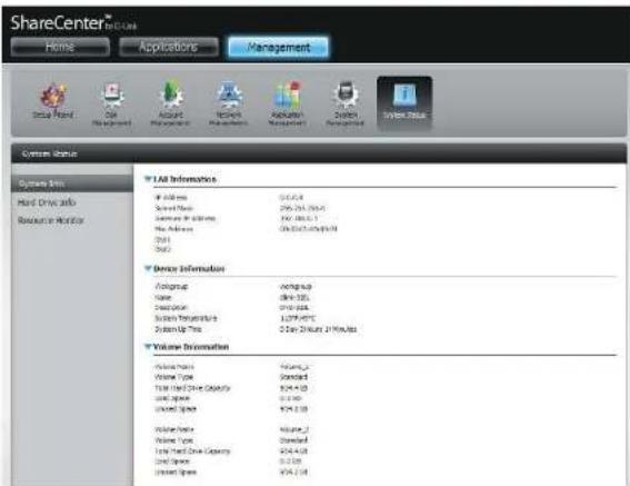
text_image
ShareCenter Home Applications Management System Status System Type Hind Drive Info Resource Monitor * All InformationAddress 00/04
Served Data 296-754 (30.0) Services For Windows 176-383 (3.1) New Address 09-54-07 (49.0) Data Device Information Alogroup Working-up Name Dine-325 Description Dine-325 System Management 1127-800 (3.1) System Up Time 2 Day 20:00 PM 21 PM ALS Volume Information Volume Type Volume_2 Volume Type Standard Total Fixed Drive Capacity 824.4 KB Used Space 0.1 KB Used Space 824.4 KB Volume Type Volume_2 Volume Type Standard Total Fixed Drive Capacity 824.4 KB Used Space 0.1 KB Used Space 824.4 KBClick System Status and then Hard Drive Info.
Click the blue arrow to reveal a table of hard drive information.
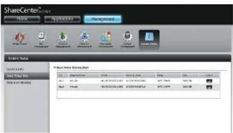
text_image
ShareCenter® Home Applications Management Order Status Search URL Last Order Info Enter History Trade Order Subscription Order Share Order Order Order Number Order Order Order Order Order Order Order Order Order Order Order Order Order Order Order Order Order Order Order Order Order Order Order Order Order Order Order Order Order Order Order Order Order Order Order Order Order Order Order Order Order Order Order Order Order Order Order Order Order Order Index Order SubscriptionSection 4 - Configuration
Click System Status > Resource Monitor, then click the blue arrow to reveal the resource details.
It provides information on the CPU, memory, bandwidth, and processes in action.

text_image
System Management System Info Hard Drive Info Resource Manager VMware-Act(36) Memory Sendshift Process
bar
| System | CPU (%) | | :--- | :--- | | Infusion Flow | 10.0 | | Infusion Flow (Max) | 10.0 | | Infusion Flow (Min) | 2.0 |
line
| Metric | Value | | :--- | :--- | | Rx | 80 | | Tx | 70 | | Total (LAN1) | 100 | | Total (LAN2) | 100 | | Time (Minutes) | 0-15 |Home
The Home tab is the center for all files on your ShareCenter. Home is divided into one main subfolder called My Folder. Under My Folder resides three main utilities, My Photos, and My Files. Let's take a closer look at all three utilities independently.
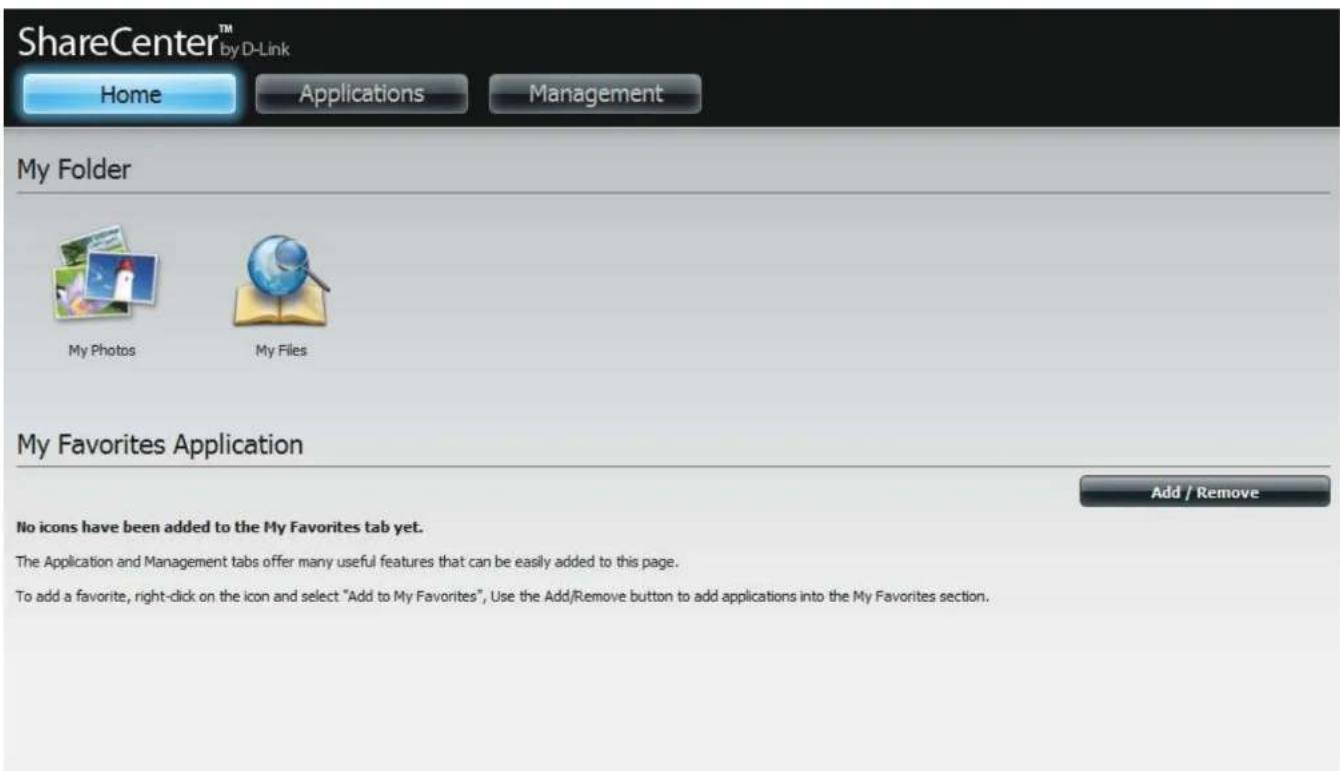
text_image
ShareCenter™ by D-Link Home Applications Management My Folder My Photos My Files My Favorites Application Add / Remove No icons have been added to the My Favorites tab yet. The Application and Management tabs offer many useful features that can be easily added to this page. To add a favorite, right-click on the icon and select "Add to My Favorites", Use the Add/Remove button to add applications into the My Favorites section.My Photos
My Photos is an utility to create albums on the ShareCenter and share photos via Google+ and Cooliris. Click the My Photos icon to open the window (displayed below).

text_image
ShareCenter™ My D-Link Home Applications Management My Photos Photo Albums Photo Colony Create > Edit Delete None albums, please click "Creative" button to create an album or click "TechTalk" button to rebuild database. HNTS... My Photo is an application that allows you to store photos under an album on your ShareCenter NAS. The My Photo Application Console of the New Configuration Window - Photo Center Photo Center concepts of two main categories: Photo Albums and Photo Gallery. Help... Photo Albums Photo Albums allow you to create completely editable albums on your NAS. There are two ways to create any album. The first option is to upload images from a workstation or from the NAS. Upload from my computer: Creating an album from a workstation as easy. Enter an album name and description. You will be pushed to a new window. Here you are given the option to browse filters on your workstation where a collection of your photos might create. Once you have selected for your image collection (you can click one image to several images of the same line to select them), click Next. The zoom will restrict you to the main Album window. In the new Album window on album is created with a handwritten image of the album you just created and a title. Upload from NAS When uploading images from the NAS, it has different properties than uploading from a workstation. Click the Upload from NAS link: The Croatia Album award prompts you to enter an Album Name and description. The next screen shows the Volume(s) on your NAS. It also shows other filters within the Volume. Record one of the Ndot or create a new folder and click Apply. This wizard does not create an album for you but creates a folder. Once the folder is created, click it. This opera monster screen where you can add photos from a workstation PC or NAS. Add photo to your album in a center way, clicking on a photo select it. Once D-LinkCreating an Album
Move your mouse and hover over the Create button. Two options become available: Upload from my computer and Upload from NAS.
Click Upload from my computer.
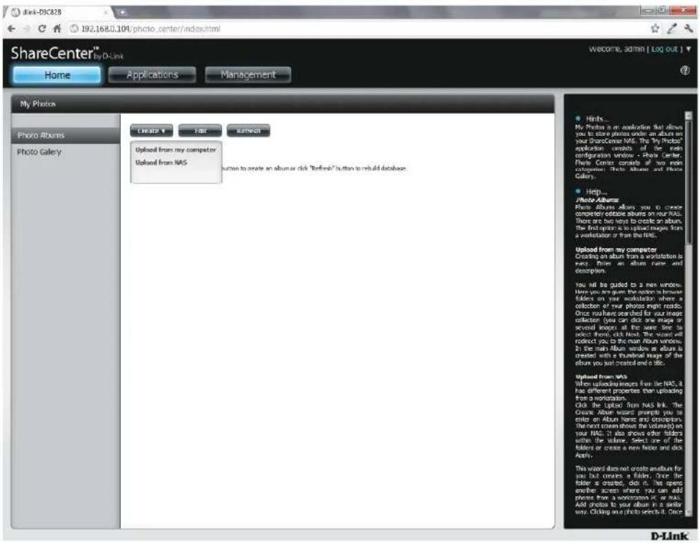
text_image
ShareCenter™ My D-Link Home Applications Management My Photos Photo Albums Photo Gallery Create Fair Select Uploaded from my computer Uploaded from NAS Hicks... My Photos is an application that allows you to store photos under an album on your ShareCenter NAS. The "My Photos" application consists of the main configuration window - Photo Center, Photo Centers contains 20 main categories: Photo Albums and Photo Galleries. Help... Photo Albums Photo Albums about you to create complementary download albums on your NAS. There are two ways to create an album. The first option is to upload images from a workstation or from the NAS. Upload from my computer Creating an album from a workstation is very. Click an album have and accept them. You will be clicked to a new window. Here you are given the options to remove folders on your workstation where a collection of your photos might read. Once you have searched for your image collection, you can click one magic or secret images all the same time to select them, click Next. The window will redirect you to the main Album windows. In the main Album window we album is created with a textual image of the album you just created and a disc. Uploaded from NAS When uploading images from the NAS, it has different properties than uploading from a workstation. Click the upload from NAS link. The Create Album Wizard prompts you to enter an Album Name and description. This next stream shows the volume on your NAS. It also shows other folders within the volume. Select one of the folders or create a new folder and click About. This wizard does not create another for you but creates a folder. Once the folder is created, click it, this open another screen where you can add phones from a workstation or in NAS. Add photos by your album is a daily way. Clicking on a photo select it. Once D-LinkPhoto Album Wizard
The Photo Album Wizard will assist you with uploading photos from your computer to the ShareCenter. The first step is to create an Album.
In the Album Name field, enter your desired name and then enter a description in the Description field. Click Next to continue.

text_image
Create Album Album Name Description Next ExitSection 4 - Configuration
Under the Select Photo section, click the browse button to search your computer for your photos.
If you wish to add more than one photo repeat the process or hold the Shift/Control button on your keyboard and select the photos to add.
Click the Open button to add them to the Album.

text_image
Select Photo Browse Previous Next Exit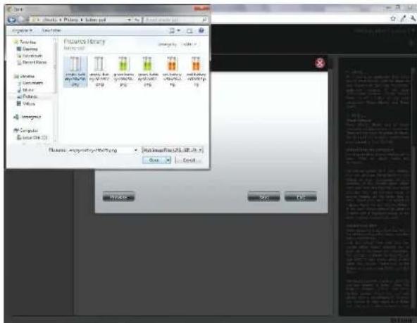
text_image
File Edit Tools Tools Help Properties Visuals Visuals Visuals Visuals Visuals Visuals Visuals Visuals Visuals Visuals Visuals Visuals Visuals Visuals Visuals Visuals Visuals Visuals Visuals Visuals Visuals Visuals Visuals Visuals Visuals Visuals Visuals Visuals Visuals Visuals Visuals Visuals Visuals VisualsSection 4 - Configuration
The Photo Album Wizard is now populated with the photos you have selected. Click Next to upload the photos.
ShareCenter automatically updates the photos to the NAS.

text_image
Select Photo empty-battery-256x25... (21.11KB) Browse Previous Next EXIT
text_image
Screenshot of a software interface with a circular progress indicator and Chinese text content on the right panel.Section 4 - Configuration
The Photo Album now features your Album.
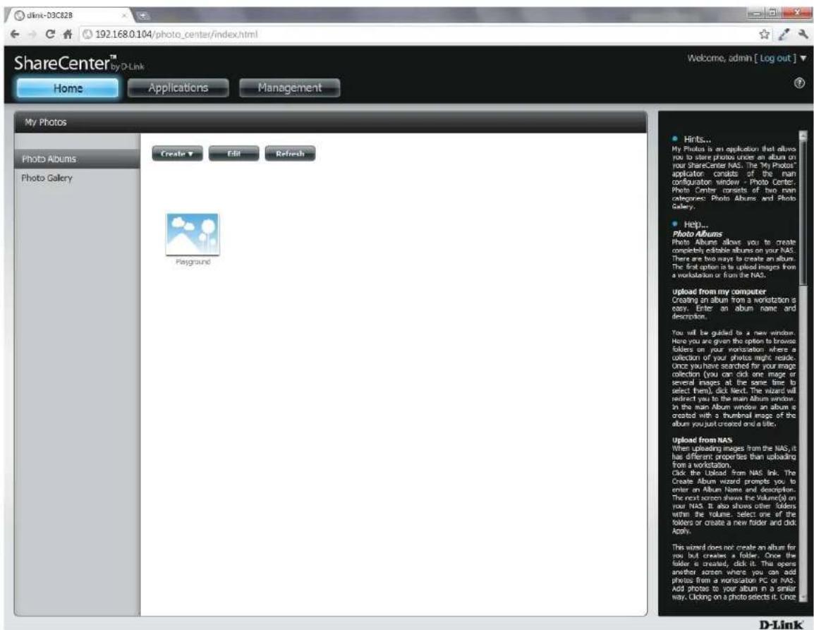
text_image
dink-D3C828 192.168.0.104/photo_center/index.html ShareCenter™ by D-Link Home Applications Management My Photos Photo Albums Photo Gallery Create Edit Refresh Playground Hints... My Photos is an application that allows you to store photos once an album on your ShareCenter NAS. The "My Photos" applicator consists of the main configuration window - Photo Center: Photo Center consists of two main categories: Photo Albums and Photo Gallery. Help... Photo Albums Photo Albums allows you to create completely editable albums on your NAS. There are two ways to create an album. The final option is to upload images from a workstation or from the NAS. upload from my computer Creating an album from a workstation is easy. Enter an album name and description. You will be guided to a new window. Have you are given the option to browse folders on your workstation where a collection of your photos might reside. Once you have searched for your image collection (you can click one image or several images at the same time to select them), click Next. The wizard will redirect you to the main Album window. In the main Album window an album is created with a thumbnail image of the album you just created and a title. Upload from NAS When uploading images from the NAS, it has different properties than uploading from a workstation. Click the Upload from NAS link. The Create Album Wizard prompts you to enter an Album Name and description. The next screen shows the Volume(s) on your NAS. It also shows other folders within the volume. Select one of the folders or create a new folder and click Apply. This wizard does not create an album for you but creates a folder. Once the folder is created, click it. This opens another season where you can add photos from a workstation PC or NAS. Add photos to your album in a similar way. Clicking on a photo selects it. Once D-LinkEditing the Photo Album
Go to Home > My Photos > Photo Albums and click Edit. The button set at the top changes to Move, Delete, Share.
Click the album(s) you want to edit or click the checkbox next to Select All.

text_image
ShareCenter® Home Applications Managements my Photo Help All Play History Cable Ask Showout Image Apply Add to the image that does you use a new computer or any other type of software. For the "Share Center" (10.0.2.1), you can use a new computer or any other type of software. You can use a new computer or any other type of software. You can use a new computer or any other type of software. You can use a new computer or any other type of software. You can use a new computer or any other type of software. You can use a new computer or any other type of software. You can use a new computer or any other type of software. You can use a new computer or any other type of software. You can use a new computer or any other types of software. You can use a new computer or any other types of software. You can use a new computer or any other types of software. You can use a new computer or any other types of software. You can use a new computer or any other types of software. You can use a new computer or any other types of software. You can use a new computer or any other types of software. You can use a new computer or any other types of software. You can use a new device in your own system. You can use a new device in your own system. You can use a new device in your own system. You can use a new device in your own system. You can use a new device in your own system. You can use a new device in your own system. You can use a new device in your own system. You can use a new device in your own system. You can use a new device in your own system. You can use a new device in your own system. Add to the image on the right. You can use a new device in your own system. You can use a new device in your own system. You can use a new device in your own system. You can use a new device in your own system. You can use a new device in your own system. You can use a new device in your own system. You can use a new device in your own system. You can use a new device in your own system. You can use a new device in your own system. You cannot use the old version of the old version of the old version of the old version of the old version of the old version of the old version of the old version of the old version of the old version of the old version of the old version of the old version of the old version of the old version of the old version of the old version of the old version of the old version of the old version of the old version of the old version of the old version of the old version of the old version of the old version. Add to the image on the right. You can use a new device in your own system. You can use a new device in your own system. You can use a new device in your own system. You can use a new device in your own system. You can use a new device in your own system. You can use a new device in your own system. You can use a new device in your own system. You can use a new device in your own system. You can be used to create an icon for creating an icon, but it is not currently created as it is currently created as it is currently created as it is currently created as it is currently created as it is currently created as it is currently created as it is currently created as it is currently created as it is currently created as it is currently created as it is currently created as it is currently created as it is currently created as it is currently created as it is currently created as it is currently created as it is currently created as it is currently created as it is currently created as it is currently created as it's currently created as it's currently created as it's currently created as it's currently created as it's currently created as it's currently created as it's currently created as it's currently created as it's currently created as it's currently created as it's currently created as it's currently created as it's currently created as it's currently created as it's currently created as it's currently created as it's currently created as it's currently created as it's currently created as it's currently created as it is currently created as it's currently created as it's currently created as it's current created as it's current created as it's current created as it's current created as it's current created as it's current created as it's current created as it's current created as it's current created as it's current created as it's current created as it's current created as it's current created as it's current created as it's current created as it's current created as it's current created as it's current created as it's current created as it's current created as it's still current created as it's current created as it's current created as it's current created as it's current created as it's current created as it's current created as it's current created as it's current created as it's current created as it's current created as it's current created as it's current created as it's current created as it's current created as it's current created as it's current created as it's current created as it's current created as it's current created as it is current created as it is current created as it is current created as it is current created as it is current created as it is current created as it is current created as it is current created as it is current created as it is current created as it is current created as it is current created as it is current created as it is current created as it is current created as it is current created as it is current created as it is current created as it is current created as it is current created as it was current created as this was currently created at this point, but this was not currently created at this point, but this was not currently created at this point, but this was not currently created at this point, but this was not currently created at this point, but this was not currently created at this point, but this was not currently created at this point, but this was not currently created at this point, but this was not currently created at this point, but this was not currently created at this point, but this was not currently created at this point, but this was also visually represented by an icon.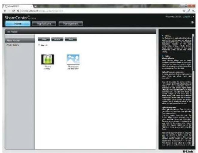
text_image
ShareCenter® Home Applications Management File Tools Main Store Photo Salary New Quick Back Select All Share Battery Background Air and Ship Add to the new computer using all other features in the main store. Only one of the main stores are used to create a new product. The main store is also used to create a new product in the main store. D-LinkMoving a Photo
Select the Album/photos you want to edit and click Move.
At the top of the editing wizard, you have the option to skip the file if it exists or overwrite it. Select an album that you want to move photos to and click Apply.
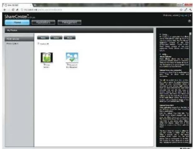
text_image
ShareCenter File Edit View Help Share Center File Edit View Help Share Center Share Center Share Center Share Center Share Center Share Center Share Center Share Center Share Center Share Center Share Center Share Center Share Center Share Center Share Center Share Center Share Center Share Center Share Center Share Center Share Center Share Center Share Center Share Center Share Center Share Center Share Center Share Center Share Center Share Center Share Center Share Center Share Center Share Center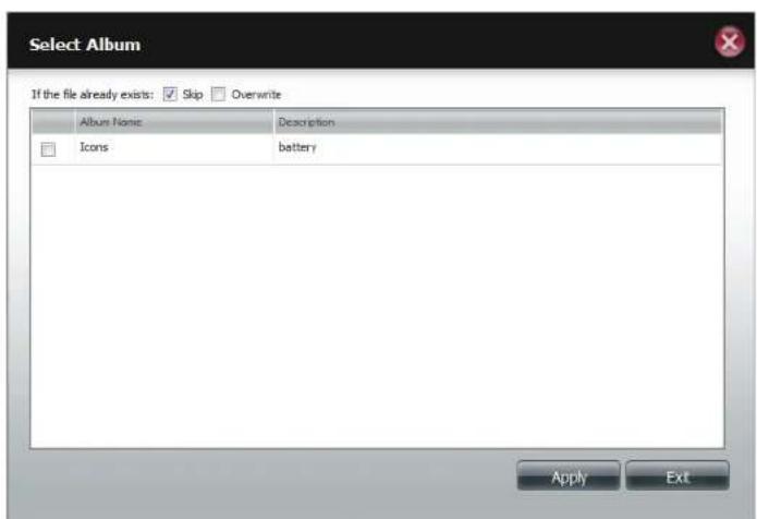
text_image
Select Album If the file already exists: ✓ Skip □ Overwrite Album Name Description Icons battery Apply ExtDeleting the Albums
Select the album you wish to delete or click the Select All checkbox. Click the Delete button. A warning message will appear to confirm whether you want to delete the album. Click Yes to delete the album or click No to not delete it.
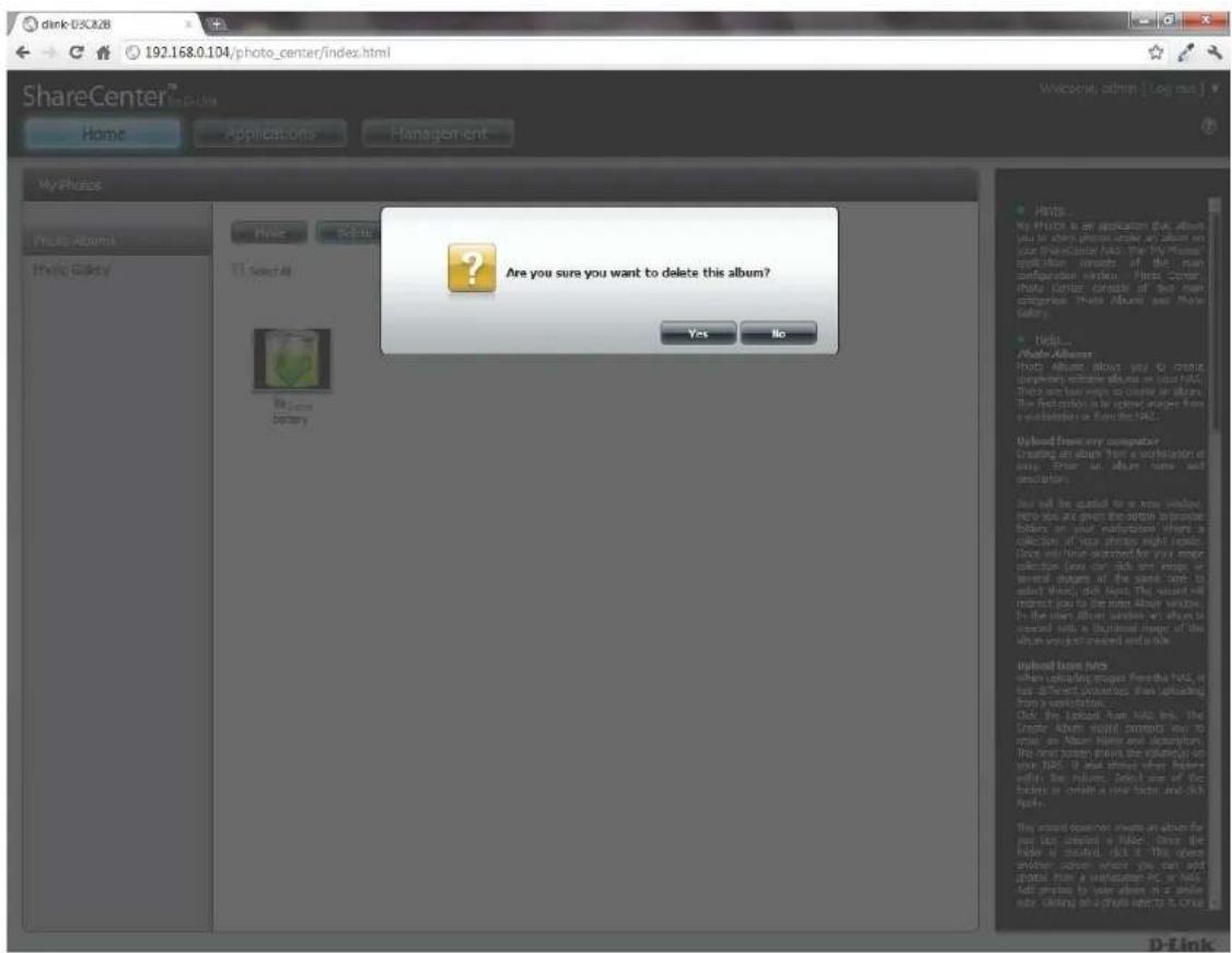
text_image
dink iSLC28 192.168.0.104/photo_center/index.html ShareCenter™ Home Applications Management My iPhone Photo Albums Photo Gallery Hi: See All Bil.com Sperry Are you sure you want to delete this album? Yes No Hips... Photo Albumer Photo Albumer allows you to create completely accessible albums on your HAC. These are now ways to create all albums. The following is the original image from a software or file in HAC. Upload from any computer Creating an album then a consultation is easy. There is album time and description. I can be added to a new window into you are given the option to prepare filters on your instructions where to collect out my photos and images. Does you have answered for your major selection (you can click any image or several images of the same core to select) when dot look. The user will respond you to the risks about what's in the other album when it looks in content with a detailed view of the album's pocket created and a look. Upload home files when controlling images from this HAC, it has different images than uploading from a conversation. Click the upload from HAC, the Under Review panel attempts one to install an Alter Image and description. This order shows the volume(s) on your HAC. It also shows when filters within the library. Select one of the filters or other a new ticket and click April. This order does not change an album for your list created a folder. Once the filter is created, click it. This opening another column which you can add some information on your HAC. Full print to your album at a single hour. Click on a photo setting it once.Sharing your Photos
To share your photos select a photo album by clicking it. Then hover your mouse cursor over the Share button. Click Mail from the drop-down menu to continue. You must select a photo album before proceeding.
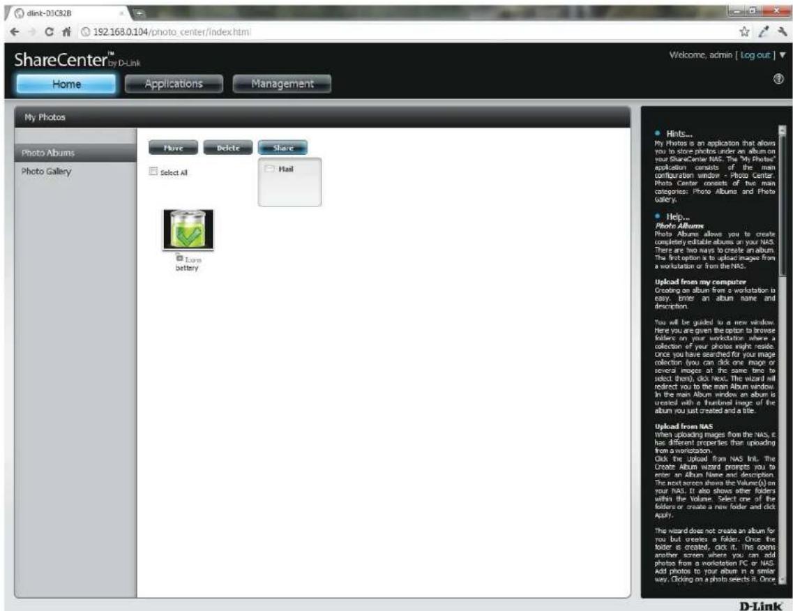
text_image
dlink-D1C32B 192.168.0.104/photo_center/index.html ShareCenter™ Welcome, admin [ Log out ] Home Applications Management My Photos Photo Albums Photo Gallery More Delete Share Select All Hail Lore battery • Hints... My Photos is an application that allows you to store photos under an album on your ShareCenter NAS. The My Photo's application consists of the main configuration window - Photo Center. Photo Center consists of two main categories: Photo Albums and Photo Gallery. • Help... Photo Albums Photo Albums allows you to create completely editable albums on your NAS. There are two ways to create an album. The first option is to upload images from a workstation or from the NAS. Upload from my computer Creating an album from a workstation is easy, enter an album name and description. You will be guided to a new window. Here you are given the option to browse folder on your workstation where a collection of your photos might reside. Once you have searched for your image collection (you can click one image or several images at the same time to select them), click Next. The Wizard will indirect you to the main Album window in the main Album window on album is created with a frontal image of the album you just created and a title. Upload from NAS when uploading images from the NAS, it has different properties than uploading from a workstation. Click the Upload from NAS Init. The Create Album Wizard prompts you to enter an Album Name and description. The next screen shows the Volume(s) on your NAS. It also shows other folders within the Volume. Select one of the folders or create a new folder and click Apply. The Wizard does not create an album for you but creates a folder. Once the folder is created, click it. This opens another screen where you can add photos from a workstation PC or NAS. Add photos to your album in a similar way. Clicking on a photo selects it. Once D-LinkSection 4 - Configuration
If you receive an error message, it means you haven't setup your email settings. Click the link provided to configure your email settings if you haven't configured it before.
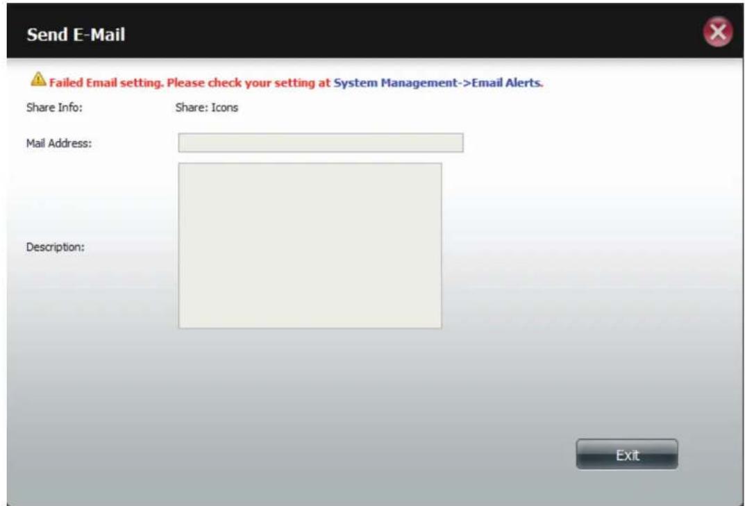
text_image
Send E-Mail Failed Email setting. Please check your setting at System Management->Email Alerts. Share Info: Share: Icons Mail Address: Description: ExitSection 4 - Configuration
Alternatively, if you have already configured the email settings, enter the email address in the Mail Address field and enter a description in the Description field. Click Apply to send the mail.
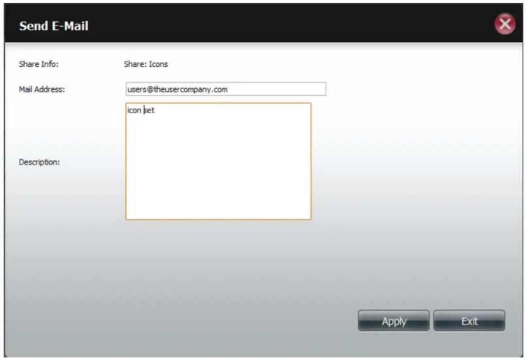
text_image
Send E-Mail Share Info: Share: Icons Mail Address: users@theusercompany.com icon let Description: Apply ExitRefresh your Photos
Click the Refresh button to refresh the images on the page. A warning message appears asking you if you want to refresh the database. Click Yes to continue or No to not refresh it.

text_image
ShareCenter™ Share Center™ File Edit View Help Share Center™ Photo History Photo Gallery Search For Edit Review © 2017 © 2018 © 2019 © 2020 © 2021 © 2022 © 2023 © 2024 © 2025 © 2026 © 2027 © 2028 © 2029 © 2030 © 2031 © 2032 © 2033 © 2034 © 2035 © 2036 © 2037 © 2038 © 2039 © 2040 © 2041 © 2042 © 2043 © 2044 © 2045 © 2046 © 2047 © 2048 © 2049 © 2050 © 2051 © 2052 © 2053 © 2054 © 2055 © 2056 © 2057 © 2058 © 2059 © 2060 © 2061 © 2062 © 2063 © 2064 © 2065 © 2066 © 2067 © 2068 © 2069 © 2070 © 2071 © 2072 © 2073 © 2074 © 2075 © 2076 © 2077 © 2078 © 2079 © 2080 © 2081 © 2082 © 2083 © 2084 © 2085 © 2086 © 2087 © 2088 © 2089 © 2090 © 2091 © 2092 © 2093 © 2094 © 2095 © 2096 © 2097 © 2098 © 2099 © 2100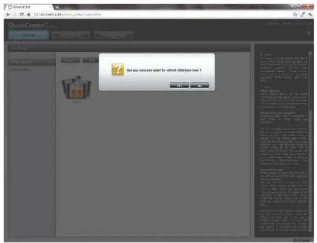
text_image
ShareCentre Are you can you want to switch distance now?Configuring an Album
Once you have completed adding photos to an album, you can view all the photos by clicking the album. You can add more photos to the album by moving your mouse over the Add button. Here you have two choices, similar to when you first added photos to the album, Upload from my computer or Upload from NAS. Follow the instructions on the wizard to proceed.
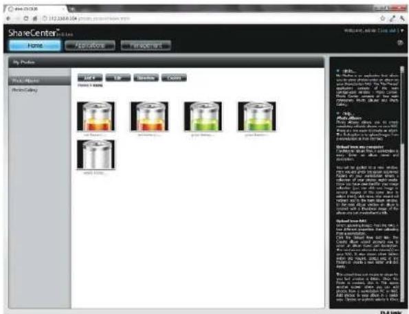
text_image
ShareCenter File Edit View Insert Help Share Center File Edit View Insert Help Share Center File Edit View Insert Help Share Center File Edit View Insert Help Share Center File Edit View Insert Help Share Center File Edit View Insert Help Share Center File Edit View Insert Help Share Center File Edit View Insert Help Share Center File Edit View Insert Help Share Center File Edit View Insert Help Share Center File Edit View Insert Help Share Center File Edit View Insert Help Share Center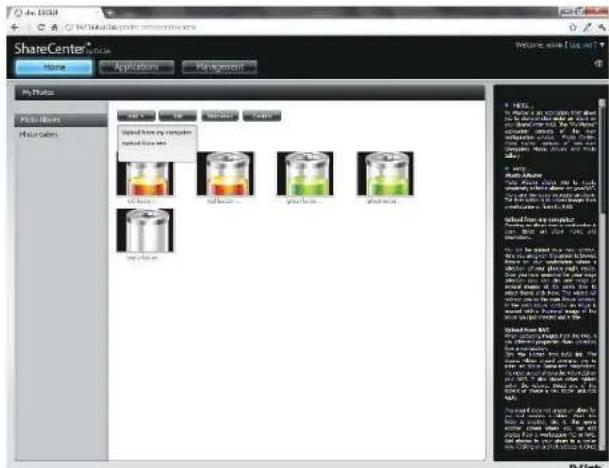
text_image
ShareCenter Home Applications Management My Photo Photo Barers Photo Barers Image from my computer modified by the Image Barers Image Barers Image Barers Image Barers Image Barers Image Barers Image Barers Image Barers Image Barers Image Barers Image Barers Image Barers Image Barers Image Barers Image Barers Image Barers Image Barers Image Barers Image Barers Image Barers Image Barers Image Barers Image Barers Image Barers Image Barers Image Barer Image Barer Image Barer Image Barer Image Barer Image Barer Image Barer Image Barer Image Barer Image Barer Image Barer Image Barer Image Barer Image Barer Image Barer Image Barer Image Barer Image Barer Image Barer Image Barer Image Barer Image Barer Image Barer Image Barer Image Barer Image Bar: Image From Web (http://www.10.1234)Section 4 - Configuration
Selecting Upload from my computer allows you to browse your computer to find more photos to add to the album. Click Browse to find the photo(s). Click Next and the new photos will be added to the album.
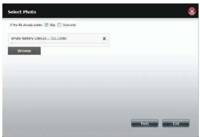
text_image
Select Photo If the file already exists: ✓ Skip ✓ Overwrite empty-battery-256x25... (21,11KB) Browse Next Exit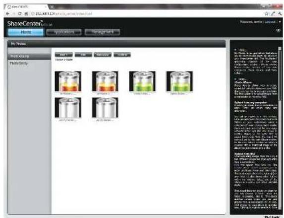
text_image
ShareCenter Share Center Home Applications Management In Table Share Center Share Only Volume 100% Volume 200% Volume 300% Volume 400% Volume 500% Volume 600% Volume 700% Volume 800% Volume 900% Volume 1000% Volume 1100% Volume 1200% Volume 1300% Volume 1400% Volume 1500% Volume 1600% Volume 1700% Volume 1800% Volume 1900% Volume 2000% Volume 2100% Volume 2200% Volume 2300% Volume 2400% Volume 2500% Volume 2600% Volume 2700% Volume 2800% Volume 2900% Volume 3000% Volume 3100% Volume 3200% Volume 3300% Volume 3400% Volume 3500% Volume 3600% Volume 3700% Volume 3800% Volume 3900% Volume 4000% Volume 4100% Volume 4200% Volume 4300% Volume 4400% Volume 4500% Volume 4600% Volume 4700% Volume 4800% Volume 4900% Volume 5000% Volume 5100% Volume 5200% Volume 5300% Volume 5400% Volume 5500% Volume 5600% Volume 5700% Volume 5800% Volume 5900% Volume 6000% Volume 6100% Volume 6200% Volume 6300% Volume 6400% Volume 6500% Volume 6600% Volume 6700% Volume 6800% Volume 6900% Volume 7000% Volume 7100% Volume 7200% Volume 7300% Volume 7400% Volume 7500% Volume 7600% Volume 7700% Volume 7800% Volume 7900% Volume 8000% Volume 8100% Volume 8200% Volume 8300% Volume 8400% Volume 8500% Volume 8600% Volume 8700% Volume 8800% Volume 8900% Volume 9000% Volume 9100% Volume 9200% Volume 9300% Volume 9400% Volume 9500% Volume 9600% Volume 9700% Volume 9800% Volume 9900% Volume 100 B-LinkSection 4 - Configuration
When you want to edit specific photos, click the album. The navigation bar at the top of the widow will change with the following options: Add, Edit, Slideshow, and Cooliris. Click the Edit button to show all the photos in the album. The navigation bar now changes to Move, Delete, Set Cover, and Share. We have already covered Move and Delete in earlier sections so please refer to those sections.
To change the cover of your album, select the photo and click Set Cover. A warning message appears asking you if you want to set the image as a cover. Click Yes to continue or No to not update it.
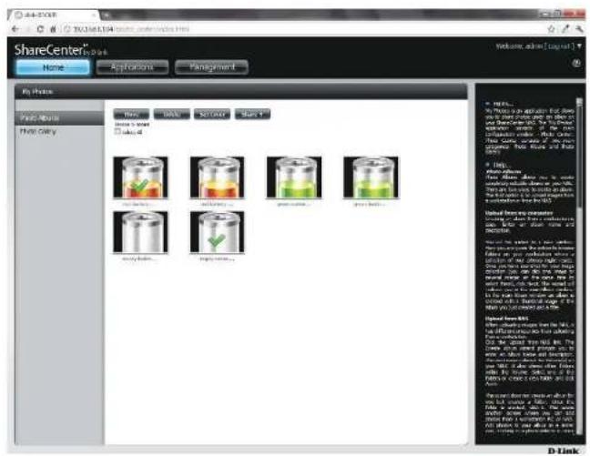
text_image
ShareCenter Home Applications Parting My Phase Paste Books Print Copy New Add Solve Save 1 Home & Store Used Add Add Solve Save 2 Add Solve Add Add Add Add Add Add Add Add Add Add Add Add Add Add Add Add Add Add Add Add Add Add Add Add Add Add Add Add Add Add Add Add Add Add Add Add Add Add Add Add Add Add Add Add Add Add Add Add Add Add D-Link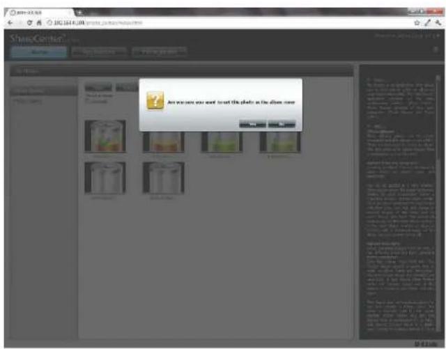
text_image
ShareConitor Are you want to treat this photo as the album nowSharing Photos on Google+
D-Link has created a direct link to Google+ so you can share your photos with one easy click. Select the photo(s) you want to share, move your mouse over the Share button and click the Google+ link. The browser opens a new Tab and directs you to your Google Gmail account if you are not logged in. The message informs you that your ShareCenter has directed you to the Gmail site. It will also show the IP address of your NAS.
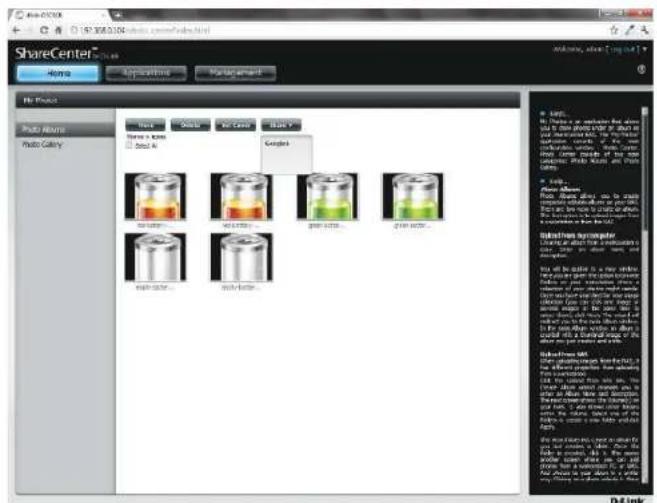
text_image
ShareCenter Share Center Home Applications Management No Place Photo Area Photo Colony Text Color Air Cover Black Name & Name Close All Examples Image Area... Image Area... Image Area... Substruts Systemcenter Drawing or adding the material in a 3D format with all parts, including parts of the main components of the material. The material is used to create a new diagram and is designed to be used to create a new diagram. The image contains an icon for the 'Water' component. The image is designed to be created using the 'Water' component in a 3D view. The 'Water' component is designed to be created using the 'Water' component in a 3D view. The 'Water' component is designed to be created using the 'Water' component in a 3D view. The 'Water' component is designed to be created using the 'Water' component in a 3D view. The 'Water' component is designed to be created using the 'Water' component in a 3D view. The 'Water' component is designed to be created using the "Water" component in a 3D view. The 'Water' component is designed to be created using the "Water" component in a 3D view. The 'Water' component is designed to be created using the "Water" component in a 3D view. The 'Water' component is designed to be created using the "Water" component in a 3D view. The 'Water' component is designed to be created using the "Water" component in a 3D view.
text_image
Accounts 192.051.04 is requesting permission to access your Google Account. Is order to access a privacy service or your account, you need to sign it. Sign in Email: Password: Sign In: Sign signature Don't access your account?Section 4 - Configuration
Next, you will be asked whether you want to grant Google access to Picasa and the photos on your ShareCenter. If you select Grant access then you will be automatically redirected to another page on your ShareCenter. If you select Deny Access then you will be directed away from Google.
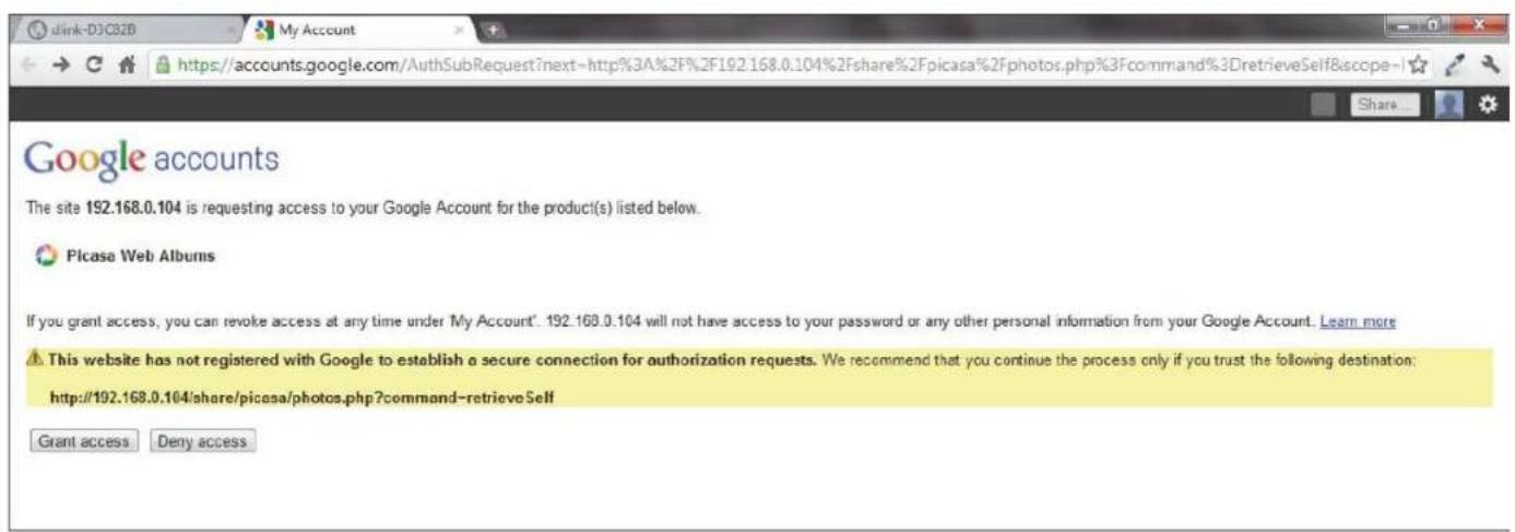
text_image
dink-DJCBID My Account https://accounts.google.com/AuthSubRequest?next=http%3A%2F%2F192.168.0.104%2Fshare%2Fpicasa%2Fphotos.php%3Fcommand%3DretrieveSelf&scope=1 Share... Google accounts The site 192.168.0.104 is requesting access to your Google Account for the product(s) listed below. Picasa Web Albums If you grant access, you can revoke access at any time under My Account'. 192.168.0.104 will not have access to your password or any other personal information from your Google Account. Learn more This website has not registered with Google to establish a secure connection for authorization requests. We recommend that you continue the process only if you trust the following destination: http://192.168.0.104/share/picasa/photos.php?command-retrieveSelf Grant access Deny accessSection 4 - Configuration
If you select Grant access, you will be directed to the ShareCenter Photo Manager. Here you can share photos to the album you already have in Picasa Web or create a new web album to share. Under Albums, select an album from the drop-down list and click Share. Alternatively, enter the new album name and click the Share button. When you click the Share button your files are uploaded to your Picasa Web Albums and another window will pop-up to confirm its success.
Note: You will have to enable Photos (Picasa Web Albums) with your Google account.
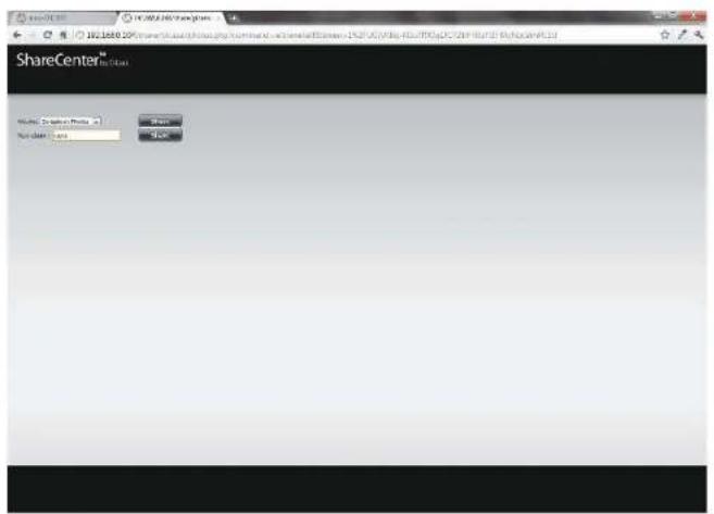
text_image
ShareCenter™ Name: Company Name: 10 User Name: 100 OK Cancel
text_image
ShareCenter Sharecenter Sharecenter Sharecenter 30Slideshow
After you have created your Album click the album once. This takes you to the full display of images in the album. Click the Slideshow button. Depending on the size and scale of your images, the browser will open a new tab and provide a full screen display of your images on the NAS. At the bottom of the image is a toolbar with information on how to view your album.
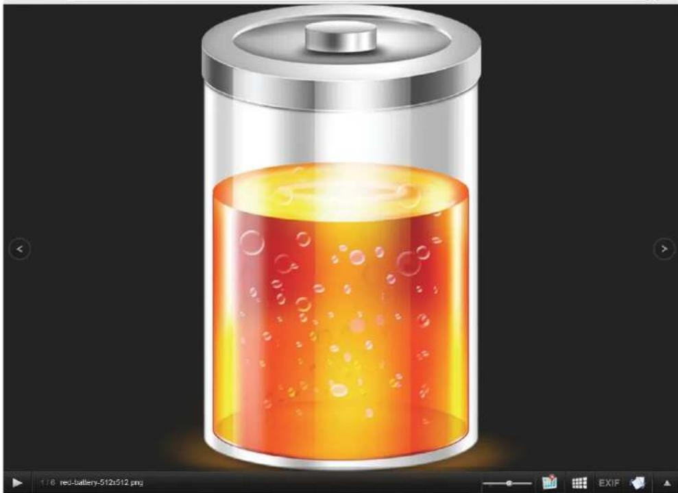
natural_image
Illustration of a cylindrical battery with orange liquid and bubbles, no text or symbols presentSlideshow Toolbar
The toolbar consists of the:
Play button: Press this button to play the Gallery images.

Photo information: View the image name and file format.
1/6 red-battery-512x512.png
Gallery speed slider: Toggle the slideshow speed between slow and fast.
GPS information: Click this button to get GPS information about the image (if your camera supports this function).
Cooliris link: Click this button to display your images on the Cooliris website.

EXIF: View detailed information about the image (File Name, Size, Image Date, Resolution, Camera, Camera Model, ISO, Exposure Time, & Aperture).

Rotation button: This rotates the image at 90 degree angles.

Gallery Navigation: This provides a pop-up display of all the images in the gallery.

Cooliris
Cooliris allows you to share photos and images on the Cooliris site. This function allows you to stream images from the DNS-320L to the Cooliris server. Please visit www.cooliris.com/desktop for more details about photo sharing with Cooliris.
Click the Cooliris button to stream images to Cooliris. Cooliris is also accessible via the Photo Gallery. You will need to install the free Cooliris plugin on your browser before you can use it.
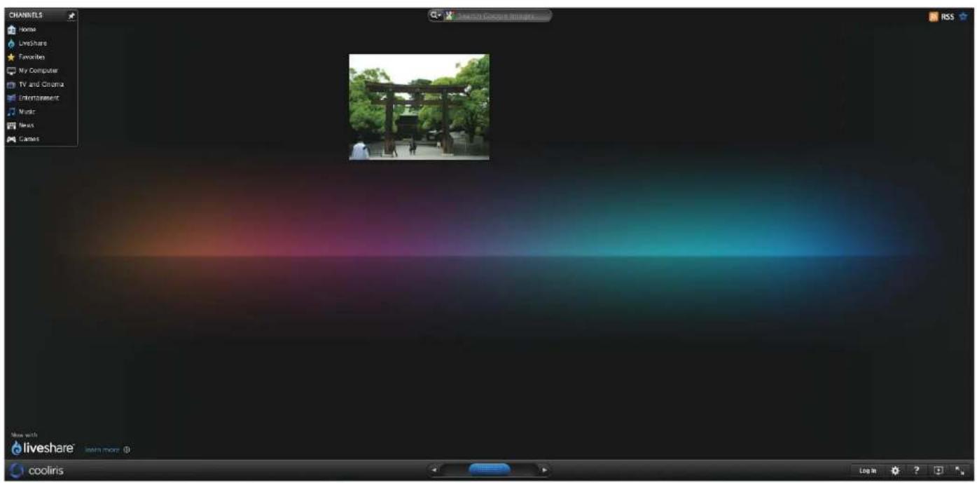
text_image
CHANNELS Home LiveShare Favorites My Computer TV and Cinema Entertainment Music News Games Search Coconut Images RSS More with liveshare® learn more (1) cooliris Log mPhoto Album - Upload from NAS
The ShareCenter also allows users to upload images that already reside on the NAS. Move your mouse over the Create button under Photo Album. Click the Upload from NAS link. Enter a Album Name and Description in the fields provided. Click Next to continue.

text_image
Create Album Album Name Description Next ExitSection 4 - Configuration
The next screen displays the Volumes on your NAS. Click the name of your Volume and select the photo(s) on the right side of the pane. Click Next to continue.

text_image
Select Photo Volume_1 New Select All dollars.png duplicate.nl... earth_00065... earth_94006... earth_globe_... earth_globe_... earth_globe_... Previous Next ExitSection 4 - Configuration
This creates a new Photo Album.
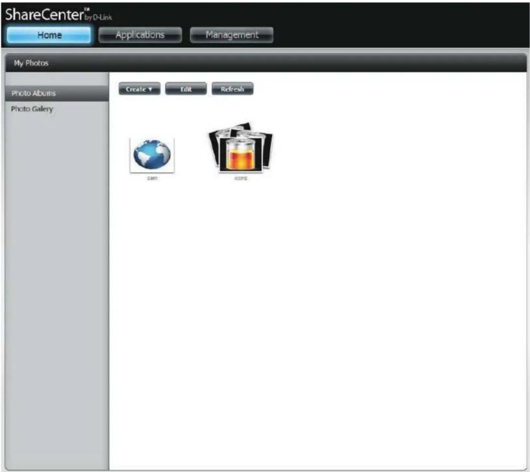
text_image
ShareCenter™ by D-Link Home Applications Management My Photos Photo Albums Photo Gallery Create ▼ Edit Refresh Sam IconsPhoto Gallery
The Photo Gallery has several options available. View the Gallery by Folder or view it by Calendar date. By default the Photo Gallery is in Folder view. Click the folder to view the images inside the Folder on your NAS. View by Calendar to see the dates under each image. You can also refresh your screen in Photo Gallery by clicking the Refresh button.
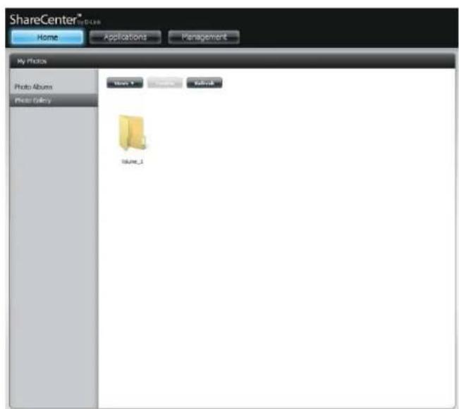
text_image
ShareCenter® Home Applications Management My Photos Photo Albums Photo Gallery Name_1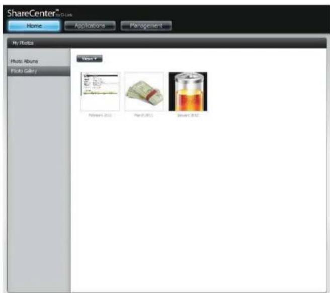
text_image
ShareCenter® Home Applications Management My Photos Photo Albums Photo Gallery Virtel * Photos 2010 Photos 2011 Photos 2012My Files
Users can access files on their ShareCenter by clicking the My Files icon in the My Folder window under Home. My Files provides access to all your files on the NAS.
Click My Files.
The My Files window provides a list of all volumes created on the NAS. Click on any Volume you created to see a directory listing of the files.

text_image
ShareCenter® My DBook Home Applications Management My Folder My Photoe My Files My Favorites Application No items have been added to the My Favorites tab yet. The Application and Management tabs offer a very useful feature that can be easily added to this page. To add a favorite, right-click on the icon and select "Add to My Favorites". Use the Additional button to add applications into the My Favorites section.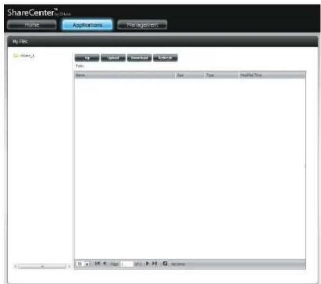
text_image
ShareCenter™ Home Applications Management My Files Mint_1 Up Download Download Refresh Help Name Set Type Modified Data 0.4.4 (Page 1) F:\F\G\homeUpload
To upload more files to the volume you have selected, click the Upload button. Click the Select Files button to find files on your computer to upload to the NAS. Locate the path of the file you want to upload and click Open.

text_image
ShareCenter™ Home Applications Management My Files Name: Volume_01 Size: 500 Type: Printbox Type folders.jpg 35.20 GB PDF Image 2012-03-17 11:19:37 applore-with-share section.jpg 402.79 GB PDF Image 2012-03-17 11:19:37 earth_35963.jpg 50.74 GB PDF Image 2012-03-17 11:19:37 earth_59388.jpg 54.33 GB PDF Image 2012-03-17 11:19:37 earth_ghde_477.jpg 35.90 GB PDF Image 2012-03-17 11:19:37 earth_ghde_522.jpg 36.25 GB PDF Image 2012-03-17 11:19:37 earth_ghde_548.jpg 34.27 GB PDF Image 2012-03-17 11:19:37 bands.io 346.00 GB CD/DVD OAA Image 2012-03-17 11:19:36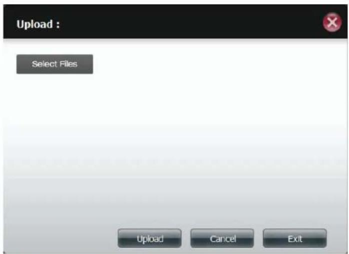
text_image
Upload : Select Files Upload Cancel ExitSection 4 - Configuration
Click Upload to start the uploading process. Then click Exit to close the upload window. The file updates to the NAS and is displayed on the directory table.
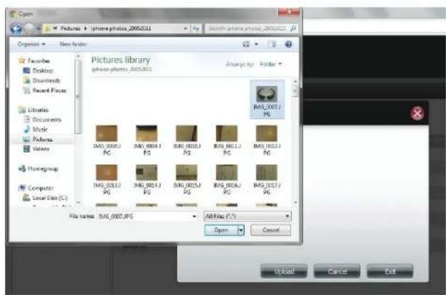
text_image
Open Pictures > iphone photos_20052011 Organize > New Folder Pictures library iphone photos_20052011 Analyze by: Folder IMG_0007.PG IMG_0008.PG IMG_0009.PG IMG_0010.PG IMG_0011.PG IMG_0012.PG IMG_0013.PG IMG_0014.PG IMG_0015.PG IMG_0016.PG IMG_0017.PG File name: IMG_0007.JPG All Files (*.*) Open Cancel Upload Cancel Exit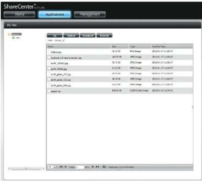
text_image
ShareCenter™ Home Applications Management My Files Up Download Download Refresh Path volume_1/ Name Size Topic Applied Type solar.org 16.35 KB PSG Image 2012-4-17 11:19:37 tasksite with above section.org 182.70 KB PSG Image 2012-4-17 11:19:37 snrfb_00001.jpg 50.73 KB PSG Image 2012-4-17 11:19:37 snrfb_9000.jpg 31.23 KB PSG Image 2012-4-17 11:19:37 snrfb_glova_972.jpg 18.38 KB PSG Image 2012-4-17 11:19:37 snrfb_glova_522.jpg 58.38 KB PSG Image 2012-4-17 11:19:37 snrfb_glova_548.jpg 14.27 KB PSG Image 2012-4-17 11:19:37 snowse.se 848.00 KB COVIO Gel Image 2012-4-17 11:34:58Download
To download files from the NAS to your computer, select the file you want to download and click the Download button. Depending on your browser download settings, the browser automatically downloads the file to your saved location.
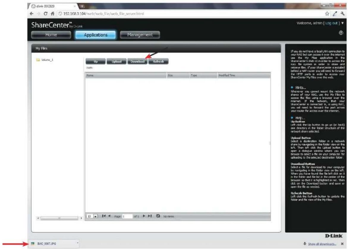
text_image
dink 032820 192.168.0.104/web/web_file/web_file_server.html ShareCenter™ My D-Link Home Applications Management Welcome, admin [ Log out ] My Files Volume_1 Up Upload Download Refresh Path: Name Size Type Modified Time If you do not have a local LAN connection to your NAS but can access it over the internet use the My File application in the ShareCenter's Web file in order to access the NAS file system in order to store and retrieve files. If your shareholder is installed behind a VART router you will need to forward the IFTP ports in order to access your ShareCenter My Files over the web. • Hints... Wherever you cannot mount the network shares of your NAS, use the My File to access the files using a browser over the internet. If the network, that your character is connected to, is using NAS, you will need to forward this port across your router for access over the internet. • Help... Up Button Left click the Up Button to go up (or back) one directory in the folder structure of the network share selected. Upload Button Select a destination folder in a network share by navigating in the folder view on the left. Then left click the Upload Button to open a dialogue window where you can browse to select a file on your computer for uploading to the selected destination folder. Download Button Select a file for download to your computer by navigating in the folder site on the left. When you have found the file left click on it in the folder and file list in the center of the browser so that it is highlighted in red. Then click on the Download Button and save or open the file as needed. Refresh Button Left click the Refresh button to update the folder and file view of the My File. BMC_0007.JPG D-Link Show all downloads...My Favorites Application
The My Favorites Application section allows users to add applications to the Home section so users can easily access these applications. Follow these easy steps to setup Favorite Applications on the Home screen.
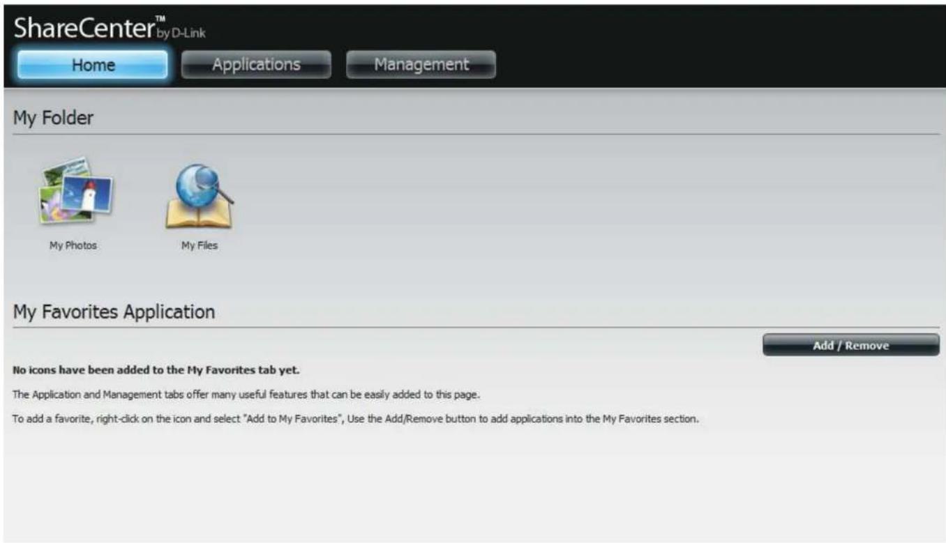
text_image
ShareCenter™ by D-Link Home Applications Management My Folder My Photos My Files My Favorites Application Add / Remove No icons have been added to the My Favorites tab yet. The Application and Management tabs offer many useful features that can be easily added to this page. To add a favorite, right-click on the icon and select "Add to My Favorites", Use the Add/Remove button to add applications into the My Favorites section.Adding Applications
Click the Add/Remove button to add Applications. Click the checkbox under each application you wish to add to the Home screen. Click Apply to continue.

text_image
Add / Remove My Favorite Application Shortcut Setup Wizard Disk Management Account Management Network Management Application Management System Management System Status FTP/HTTP Downloads Apply ExitThe shortcut is now created on the Home screen. Click the shortcut to access the application.

text_image
ShareCenter™ Home Applications Management My Folder My Files No Files My Favorites Application No items have been added to the My Favorites tab yet. The Application and Management sites of the new user profile that can be easily asked to this page. To add a file, it will also be used to create a "Add" file in My Favorites. Use the ASP/Revenue tool to allow applications to the My Favorites section.Applications
FTP/HTTP Downloads
Schedule file and folder backups from an FTP server, web server, or local network share. Always test the URL before applying changes. This will help to ensure a successful download.
Category: Use the radio buttons to select the type of server that the source files/folders for the Schedule Downloads are located on. Click the HTTP radio button to specify that the source files are located on a web server or click the FTP radio button to specify that the source files/folders are located on an FTP server.
Login Enter the login information for the site that contains the files that you want to schedule for downloading. If no password is required, choose Anonymous. If a password is required, choose Account and enter the user name and password.
Username: Enter the user name here.
Password: Enter the password here.
Type: Select either File or Folder from the drop-down list depending on whether you wish to download a file or a folder.
URL: Enter the FTP/HTTP site address for the scheduled download. Click on Test to verify access to the site address and file/folder. If you selected File from the above dropdown list, you must specify the exact file in the URL path, including the file extension. (e.g. http://example.com/test/testfile.txt).
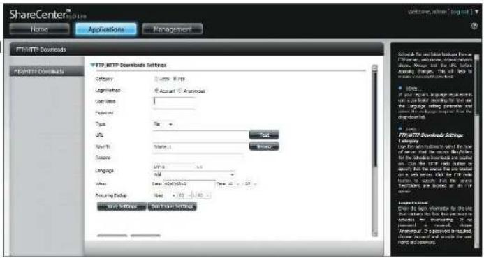
text_image
ShareCenter® Name Applications Management FTR/HTTP Downloads FTR/HTTP Downloads Settings Category Comps 8.8.8p Logarithmic # Account ▲ American User land: Password: Type File URL Search Name:1 Language Language Link: 54.6.0.0 Size Date: 02/07/2013 Time: 42.0.0.0 Acquiring Address Name: 02/07/2013 Save Settings Start New Settings Test Browse Use the information to select the user for any other than the most detailed for the website following an email on the FTR sites under the email. For all users, the FTR is used to access the website or a web page. Use the FTR to get your website from the website. To account for any other Accessories: All rights reserved. Accessories: All rights reserved. Accessories: All rights reserved.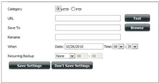
text_image
Category HTTP FTP URL Test Save To Browse Rename When Date: 10/26/2010 Time: 08 : 35 Recurring Backup None 00 : 00 Save Settings Don't Save SettingsSection 4 - Configuration
Save To: Enter the specific destination on the internal drives for the downloaded files or folders to be saved to. Click Browse to browse the internal drives.
Rename: If you would like to rename a file after it has been downloaded from the specified HTTP/FTP server, enter the name you would like the file to be renamed to in this field.
Language: Use the drop-down menu to select the language used in the file or folder that you are trying to download.
When: Select the date and time for the download to occur.
Recurring: If you wish to schedule a recurring backup, select the desired interval (daily, weekly, or monthly) and the time you want the backup to start.
Schedule Pending and completed download events will be Download listed here. The current status for each event is List: displayed here. In addition, there is an option to delete a download event at any time. Current download statistics, such as % completed and download speed, are displayed for each event. A refresh button is also provided to produce updated listings at any time.

text_image
Form1 Delete Download Form Save As Progress Default Cancel Help H 4 type 1 M > H NameRemote Backups
The Remote Backups section allows you to back up your ShareCenter to another ShareCenter, Linux Server or vice versa from a remote ShareCenter or Linux Server to your ShareCenter. Use the Create button in the remote backups list to start a wizard where you can configure the remote backup.
Enable remote backup service: Check this box to enable the remote backup server functionality to allow a remote NAS or Linux server to backup from/to your ShareCenter.
Note: If you are not using the Remote Backup functionality of your ShareCenter leave this box unchecked so that your ShareCenter's performance will not be affected by the additional overhead used by this process.
Password: Enter a password that the remote client will use to access your NAS for backup.
Remote Backups This is the list of remote backup jobs. list:
Create: Click the Create button to build a new remote backup job on your ShareCenter.
Modify: Click this button to make changes to your existing Remote Backup jobs in the Remote Backup list. You must select the remote backup job first and then click the Modify button.
Delete: To remove a Remote Backup job select the job in the list and then click the Delete button.
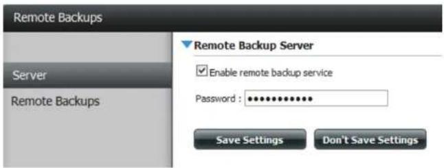
text_image
Remote Backups Server Remote Backups Remote Backup Server Enable remote backup service Password : ************ Save Settings Don't Save Settings
text_image
Remote Backups Create Modify Delete Test Schedule Style Change Settings Preset Page 1 MP F P Q NumbersCreate Wizard
When you click the Create button above the Remote Backup list a wizard will start, guiding you to configure a new Remote Backup job.
Welcome: Displays the steps of the wizard.
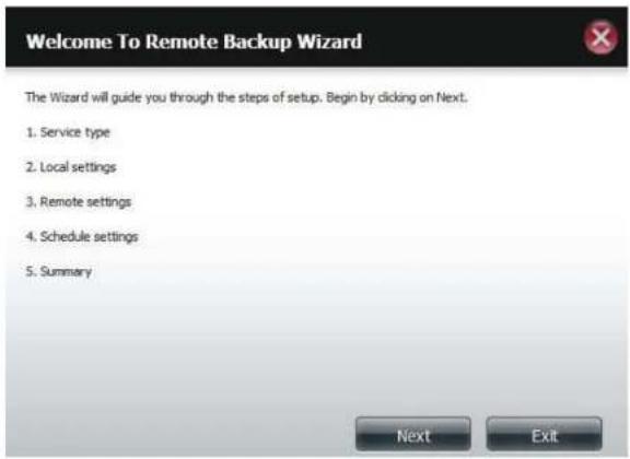
text_image
Welcome To Remote Backup Wizard The Wizard will guide you through the steps of setup. Begin by clicking on Next. 1. Service type 2. Local settings 3. Remote settings 4. Schedule settings 5. Summary Next ExitService Type: NAS to NAS: backup from the local NAS to a remote NAS or vice versa.
NAS to Linux backup from the local NAS to a Linux file system or vice versa.
Local to Remote: sets the backup source as the local NAS and the target destination for the backup files as the remote NAS or Linux file system.
Remote To Local: sets the backup source as the remote NAS or Linux file system and the target destination for the backup files as the local NAS.
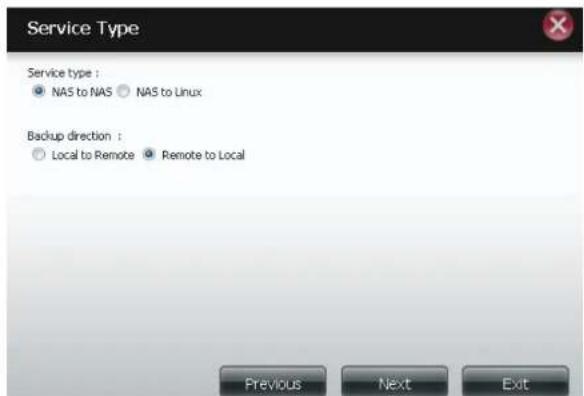
text_image
Service Type Service type : • NAS to NAS • NAS to Linux Backup direction : ○ Local to Remote ● Remote to Local Previous Next ExitSection 4 - Configuration
Local Settings:
Task (Name): the name used to refer to the backup job which will be listed later in the Remote Backup list.
Folder Path: select a local network share folder or file as the target or source for the backup job.
Remote Settings:
Remote IP: The backup process uses Rsync protocol and needs to know the IP address of the destination source or target device for the backup. Input the IP of the remote NAS or Linux file system.
Password: Enter the password that is used by the remote backup server on the remote NAS or Linux file system.
Enable Encryption: Checking this box will enable SSH encryption of the files that are transferred (backed up) over the network between the local and remote devices.
Ignore existing file(s): Checking this box prevents the backup process from writing over any files in the target file system that are not part of the backup files or folders. Therefore any existing files in the target system are preserved.
Incremental backup support Num (#): Checking this box provides multiple backup-capability at scheduled times. The first backup in an incremental series captures all the files for backup. Subsequent backups are incremental in that only the files and the folders that have changed in the backup source since the last incremental backup will need to be backed up. Each incremental backup builds a complete snapshot of the backup source however only the initial backup contains all the original files and folders. The subsequent backups in the incremental series contain new files and folders plus the links to the first incremental backup.
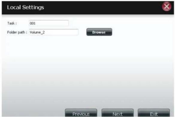
text_image
Local Settings Task : 001 Folder path : Volume_2 Browse Previous Next Exit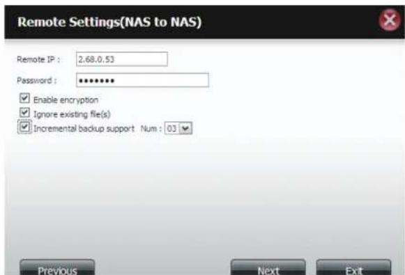
text_image
Remote Settings(NAS to NAS) Remote IP : 2.68.0.53 Password : ******** Enable encryption Ignore existing file(s) Incremental backup support Num : 03 Previous Next ExitRemote Remote Path: Using the Browse button, select the file system (folder) path to the remote target or source system for backup.
Schedule Scheduled Mode:
Settings: Manual: Check either Yes or No selection below to start the backup (yes) immediately on completion of the wizard or (no) manually start the backup from the Remote Backup list.
Once - Select this option to run the Remote Backup once at a specific date and time set here.
Scheduled: Select this option to set the backup to occur daily, weekly, monthly per a specific schedule.

text_image
Remote Settings Remote path : test1 Source used size : 4.0k Destination free size : 71,2G Previous Next Exit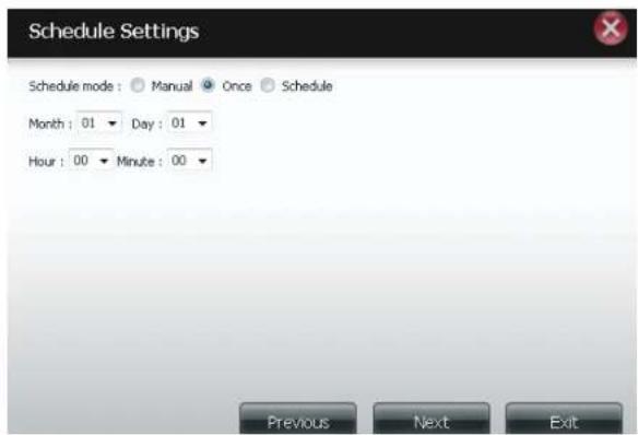
text_image
Schedule Settings Schedule mode : Manual Once Schedule Month : 01 Day : 01 Hour : 00 Minute : 00 Previous Next ExitFinished:
Click on the Finish button if you are satisfied with all the settings of the Backup job created. Otherwise click on the Previous button to go back and make changes. Alternatively click on Exit to end the configuration without adding a Remote Backup job.
Remote Backups list:
Task: The name of the Remote Backup job.
Schedule: When the Remote Backup job will execute.
Status: Current status which can be
- Ready the remote backup job is ready to be executed.
- Finished the remote backup job has executed completely and successfully.
- Failed the Remote backup job was unsuccessful during execution.
Enable/Disable: If the button shows a red circle the remote backup job is enabled. Clicking the red button will disable the remote backup job and the button will change to a green right pointing triangle. Clicking the green triangle will enable the job again.
Backup now: Clicking this button will execute the backup job immediately as long as the job is enabled.
Recovery: Clicking this button will write the backup files and folders back into the source file system from the backup target system (reverse the file direction).
Navigation buttons: Use these buttons to move up and down in the list when there are multiple jobs configured.
Refresh Button: Click this button during a backup or recovery process to monitor the progress by updating the progress completed bar.
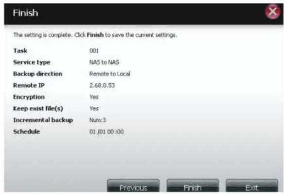
text_image
Finish The setting is complete. Click Finish to save the current settings. Task 001 Service type NAS to NAS Backup direction Remote to Local Remote IP 2.68.0.53 Encryption Yes Keep exist file(s) Yes Incremental backup Num:3 Schedule 01 /01 00 :00 Previous Finish Exit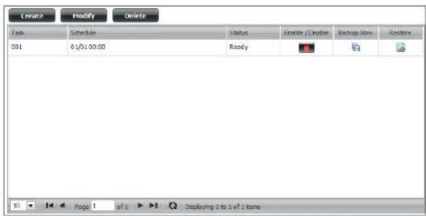
text_image
Create Modify Delete Info Schedule Status Enable / Close Backup Now Restore 001 01/01 00:00 Ready Page 1 of 1 Deploying 1 to 1 of 1 itemsLocal Backups
Schedule local file and folder backups from the local network share of the device or from the local computer. Always test the URL before applying changes. This will help to ensure a successful download.
Category: Use the radio buttons to select the backup method. If your NAS device has two volumes you can click the Internal Backup radio button to backup the data from the first volume to the second volume and vice-versa. The Internal Backup feature also allows you to backup an existing folder on a volume to another folder on the same volume but nested folders in the same volume are not allowed. If you want to backup the data from your PC or another NAS device to your NAS device, click the LAN Backup radio button.
Login Method: Enter the login information for the site that contains the files that you want to schedule downloads from. If no password is required choose Anonymous. If a password is required choose Account and provide the user name and password. This option is only available for LAN Backups.
Username: Enter the user name here.
Password: Enter the password here.
Type: Select File or Folder, depending on what you want to download or backup.
URL: Enter the path of the site or server you are initiating a transfer from. (e.g. Volume_1/Test or \192.168.0.32\Volume_1\Test\test.txt).
Save To: Enter a valid destination drive on the ShareCenter, or click Browse to select the destination.
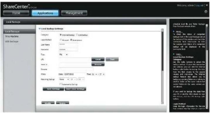
text_image
ShareCenter Home Applications Management Local Setup Local Settings Time Machine USB Setup Local Backup Settings Company: Microsoft (Local) Ltd. Local Market: Microsoft Windows User Name: Microsoft Windows Parameters: Microsoft Windows Trac: File OK: Local Print Save As: 100% Window Name: Microsoft Windows Win: Date: 04/17/2012 Time: 15:30:30 Assuming Setup: None Internal Backup: New Settings: New or New Settings Schedule Local file and file backup from the tool environment. • Results: To check the data of computer windows which include a network to the memory set. This is not the connection to the system. The connection will be displayed in the connection book. • Details: Available for these bootings Category: Use the link between to detect the bootings that use this connection to the connection set. You can use the internal bootings on the system to ensure the connection to the connection set. If you want to log your own user's connection to the system, you should note that the connection to the system will be required. If you want to log your own user's connection to the system, you should note that the connection to the system will be required. Loger Model: Show the log information for the site log model and file version required.Rename: Enter the renamed file name here.
When: Enter the date and time you want the scheduled backup or download to initiate.
Recurring Designate the interval and time you want the backup or Backup: download to run unattended.
Incremental Backup: By default all local backups and file/folder downloads are in Overwrite mode, meaning that identical files in the destination folder will be overwritten by the source files. Checking Incremental Backup will have the ShareCenter compare identical file names at the source and destination. Files will only be overwritten if the source file is more recent.
Time Machine
This section allows the user to configure the ShareCenter so that it becomes a backup destination in the Mac OS® X Time Machine. In order to use this function, the AFP service is required. The AFP service will start automatically as soon as this function is enabled.
Enable Time Machine: Click this to enable the Time Machine function to work with a Mac OS® X Time Machine. The Time Machine Settings list will appear when this checkbox is checked.
Time Machine A list of destination folders on the Network Shares associated with the Time Machine backup.
Settings list:
New: Adds a NAS folder as a Time Machine destination.
Delete: Deletes a NAS folder setup as a Time Machine destination.
Remove all Network Delete all the NAS folders in the list configured as Time Machine Destinations.
Shares:

text_image
Time Machine Local Backups Time Machine ▼ Time Machine Enable/Disable □ Enable Time Machine
text_image
Time Machine Settings New Delete Remove All Network Shares Share Name PATH 10 Page 1 of 1 No itemsUSB Backups
This section allows the user to configure the ShareCenter so that it becomes a backup destination for a USB device that is connected to your DNS-320L.
MTP Backups (Media Transfer Protocol) basically backup digital media content from a MTP compatible USB device such as digital cameras, MP3 players, and smartphones to your ShareCenter. USB Backups allows you to backup data from a USB storage device to the ShareCenter or from the ShareCenter to a USB storage device.
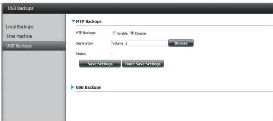
text_image
USB Backups Local Backups Time Machine USB Backups MTP Backups MTP Backups Enable Disable Destination Volume_1 Browse Status -- Save Settings Don't Save Settings USB BackupsMTP Backups
MTP Click Enable to allow your ShareCenter to copy Backups: digital media content from a MTP USB device.
Destination: Click Browse to select a folder on your ShareCenter for the backup data to be saved to.
Status: Displays the current MTP backup status.
Click on the Save Settings button to save the MTP Backups settings.
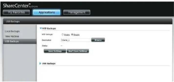
text_image
ShareCenter™ My Favorites Applications Management USB Backups Local Backups Time Machine USB Backups MTP Backups MTP backup: Double Double Destination: Volume_1 Browse Status: - Save Settings Don't Save Settings USB BackupsUSB Backups
USB Click Enable to allow your ShareCenter to copy data Backups: from/to a USB storage device.
Category: Select either USB to NAS (backup from the USB storage device to the ShareCenter) or NAS to USB (backup from the ShareCenter to the USB storage device).
Source: Click Browse to select a folder as the source folder for the backups.
Destination: Click Browse to select a folder as the destination folder for the backups.
Type: Select Copy to create a new folder in the destination folder. Select Synchronize to overwrite all the files in the existing USB folder named USBDisk1_1.
Status: Displays the current USB backup status.
Click on the Save Settings button to save the USB Backups settings.
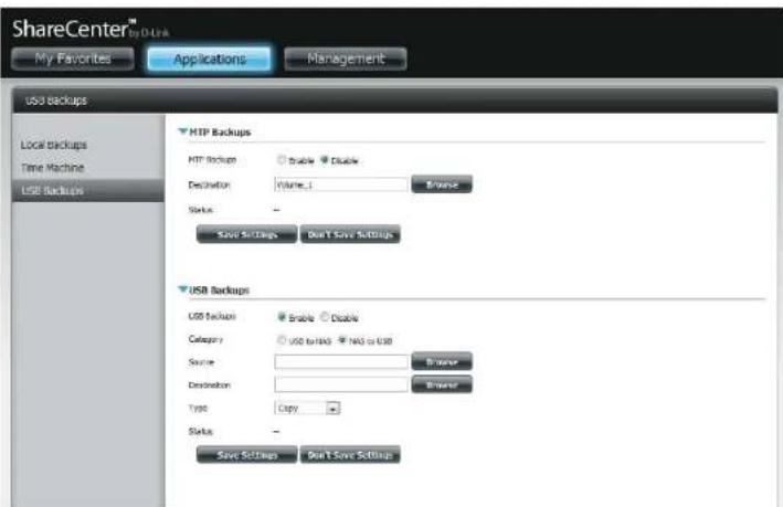
text_image
ShareCenter™ My Favorites Applications Management USB backups Local backups Time Machine USB Backups HIP Backups FTP Buckups Double Enable Destination Volume_1 Browse Status - Save Settings Don't Save Settings USB Backups USB Buckups Enable Disable Category USD to USD NAS to USD Source: Destination: Browse Type Copy: Status - Save Settings Don't Save SettingsMTP Backup Process
- Connect a MTP USB device to the USB port on the back panel of the device. The DNS-320L will enter backup mode if MTP Backups has been enabled in the MTP backup settings.

natural_image
Black SharpCenter brand device with no visible text or symbols on its body- Press the USB button to start the backup process. The blue USB LED flashes briefly to display that the backup is in the process. The ShareCenter will create a new folder in the destination folder that you selected in the MTP backups settings and will copy all the media files from the MTP USB device to this folder. At this time the USB LED remains blue until the device is disconnected.

text_image
ShareCenter| 项目名称 | 代码 | 名称 | 单价 | 成本 |
| 1.1.1 项目 | ||||
| 1.1.2 项目 | 701301568888888888888888888888888888888888888888888888888888888888888888888888888888888888888888888888888888 | 1.00 | ||
| 2.1.1 项目 | ||||
| 2.1.2 项目 | 70130156942222222222222222222222222222222222222222222222222222222222222222222222222222222222222222222222222222 | 1.00 | ||
| 3.1.1 项目 | ||||
| 3.1.2 项目 | 70130156943333333333333333333333333333333333333333333333333333333333333333333333333333333333333333333333333333 | |||
| 4.1.1 项目 | ||||
| 4.1.2 项目 | 7013015694444444444444444444444444444444444444444444444444444444444444444444444444444444 | 1.00 | ||
| 5.1.1 项目 | ||||
| 5.1.2 项目 | 7013015695000000000000000000000000000000000000000000000000000000000000000000000000 | |||
| 6.1.1 项目 | ||||
| 6.1.2 项目 | 701301569515555555555555555555555555555555555555555555555555555555555555555555555 | |||
| 7.1.1 项目 | ||||
| 7.1.2 项目 | 7013015696166666666666666666666666666666666666666666666666666666666666666666666666 | 1.00 | ||
| 7.1.1 项目 | ||||
| 7.1.2 项目 | 70130156971777777777777777777777777777777777777777777777777777777777777 | 1.00 | ||
| 8.1.1 项目 | ||||
| 8.1.2 项目 | 701301569999999999999999999999999999999999999999999999999999999999999999999999999999999999999999999999999999 | |||
| 8.1.1 项目 | ||||
| 8.1.2 项目 | 701301571111111111111111111111111111111111111111111111111 | 1.00 | ||
| 8.1.1 项目 | ||||
| 8.1.2 项目 | 70130157111111111111111111111111111111 | 1.00 | ||
| 8.1.1 项目 | ||||
| 8.1.2 项目 | 7013015712222222222222222222222222 | - | ||
Section 4 - Configuration
- Go to System Management, USB Devices. Under USB Storage Information, you will see detailed information on the device you plugged into the DNS-320L. You can connect an Android device but enable USB debugging.
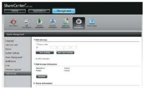
text_image
ShareCenter Name Applications Management System Management Language New Internet Device System Settings New Management Networks Logic Formant Updates Settings 100% Settings Information New Settings New Settings No. 100% Settings New Settings Information Message Model Actual Updated Preview Information- When the backup is complete, the flashing blue LED will become solid blue. Click and hold the USB button at the front and the DNS-320L unmounts the device.
natural_image
Black ShareCenter device with control buttons and indicator lights (no visible text or symbols on body)USB Backup Process
- Connect a USB storage device to the USB port on the back panel of the device. The LED will blink then become solid once it is ready for backup, if USB Backups has been enabled in the USB backup settings.
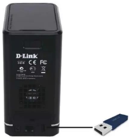
text_image
D-Link CE FC USB-
Press the USB button to start the backup process. The LED starts to blink that the backup is in the process. The ShareCenter will copy or sync all the files from the source folder to the destination folder. Please Note: No warning message will appear to indicate that all data on the destination folder will be deleted automatically.
-
When the backup is complete, the flashing blue LED will become solid blue. To unmount the USB storage device, you can click and hold the USB button at the front of the DNS-320L or you can go to the USB Devices menu of the System Management icon in the Management Tab of the Web GUI of the device. Click the blue arrow to reveal the USB Storage information. Click the Unmount button to eject the USB device.

natural_image
Black ShareCenter device with control buttons and indicator lights (no visible text or symbols on body)P2P Downloads Settings
In this menu you can configure the P2P download management settings.
P2P: Select Enable or Disable.
Download Schedule: In the block provided the user can configure the running schedule for P2P downloads. Simply select the Start and Stop block for the appropriate Time and Date.
Auto Here the user can enable or disable the automatic Download: download option.
Port Settings: The user can choose whether to allow the device to automatically choose an incoming connections port or configure the incoming connections port manually.
Seeding: Select one of the three seeding options.
Torrent Save Displays the volume where the Torrent will be saved. Path:
Encryption: Here the user can choose to enable or disable the encryption.
Bandwidth Control: You can manually configure the maximum download rate and maximum upload rate. Enter the value -1 to set the respective field to unlimited.
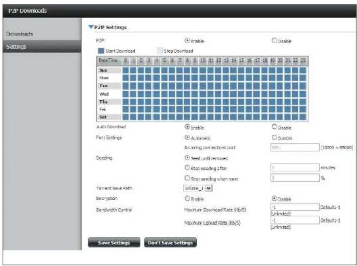
text_image
P2P Downloads Downloads Settings P2P Settings Start Download Stop Download User Time Auto Download Part Settings Seeding Tenant Save Path Encryption Bandwidth Control Enable Automatic Seeding connection time (start) Seed until removed Stop seeding after Stop seeding when next Volume_1 Enable Maximum Download Rate (Mb/s) Maximum Upload Rate (Mb/s) Disable Disable (Unlimited) (Unlimited) Disable (Unlimited) Disable (Unlimited) Disable (Unlimited) Disable (Unlimited) Disable (Unlimited) Disable (Unlimited) Disable (Unlimited) Disable (Unlimited) Disable (Unlimited) Disable (Unlimited) Disable (Unlimited) Disable (Unlimited) Disable (Unlimited) Disable (Unlimited) Disable (Unlimited) Disable (Unlimited) Disable (Unlimited)
text_image
Stop seeding when meet Torrent Save Path Encryption Enable Bandwidth Control Maximum Download Rate (Kb/S) -1 Default:-1 (Unlimited) Maximum Upload Rate (Kb/S) -1 Default:-1 (Unlimited) Disable Save Settings Don't Save SettingsDownloads
Here the user can add torrents and view P2P download lists.
Add Torrent from URL: In the field provided you can copy and paste a link to a torrent file hosted on the internet. The P2P download manager will add the torrent file to the download manager and begin downloading your files.
Add Torrent from File: Browse for a torrent file you have downloaded onto your PC.
P2P Downloads list: This window will display all the running tasks.
Remove Completed: The user can click on the Remove Completed button to remove finished downloads. Sometimes identifying finished jobs, when multiple downloads exist, can be difficult. This option makes it is easier for the user to remove finished downloads from the list with a single click.
Detail: The Details button allows the user to view the files that are being downloaded for each torrent.
Top,Up, Down,Bottom: The Top, Up, Down and Bottom buttons allow you to move the selected P2P download in the task list. The downloads at the top of the list have a higher priority than the one listed below them.
Delete: The Delete button allows the user to remove a selected download. This will remove not only the torrent file, but also the partially downloaded files too.
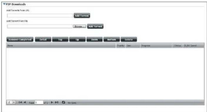
text_image
P2F Downloads Add Tarents From URL Add Torrent Add Torrent Fox File Browse Add Torrent Remove Completed Select Top Up Down Bottom Delete Name Ready Use Progress Status: SQL Speed Page 1 No DataStart / Stop: The Start and Stop buttons allow users to start and stop selected P2P downloads in the task list.
Navigation: At the bottom of the P2P Task window there are a couple of navigation controls. When multiple tasks exist, the user can select how many tasks will be displayed by using the drop-down menu. The user can also navigate to other pages when more than one page exist.
Refresh: The Refresh button allows the user to refresh the P2P task list so it displays the most updated statistics.
My Files
Whenever you cannot mount the network shares of your NAS, use My Files to access the files using a browser over the internet. If the network, that your ShareCenter is connected to is using NAT then you will need to forward HTTP port 80 across your router for access over the internet.
Up: Left click the Up button to go up (or back) one directory in the folder structure of the selected network share.
Upload: Select a destination folder in a network share by navigating in the folder view on the left. Then click the Upload button to open a dialogue window where you can browse to select a file on your computer for uploading to the destination folder.
Download: Select a file to download to your computer by navigating in the folder view on the left. When you find the file click on it in the folder. Your selection will be highlighted in red. Next click on the Download button and save or open the file as needed.
Refresh: Left click the Refresh button to update the folder and file view of My Files.
Download: Downloads the file to your computer.
Copy: Copies the file to the clipboard and opens a wizard to allow you to select the folder to paste the file into. Once you have chosen the folder clicking OK to paste the file into the folder.
Move: Moves the file to a new folder on the disk.
Delete: Removes the selected file from disk.
Rename: Allows you to configure a new file name for the selected file.
Properties: Displays the file properties such as ownership, access rights, and modify time.
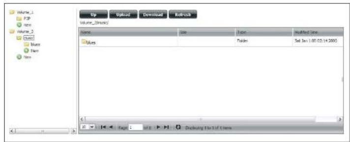
text_image
Up Upload Download Refresh Volume_1 P3P New Volume_2 Excel Blue New New Volume_1 (Main) Name: Blues Date: Time: Updated Date: Turks: Set Jan 1.00:03:14 2005 Page 1 Delaware To Do Us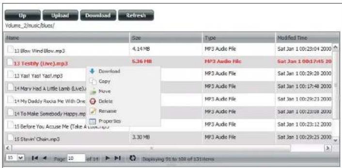
text_image
Up Upload Download Refresh Volume_2/music/Blues/ Name Size Type Modified Time 13 Blow Wind Blow.mp3 4.14 MB MP3 Audio File Sat Jan 100:23:04 2000 13 Testily (Live).mp3 5.36 MB MP3 Audio File Sat Jan 100:17:45 20 13 Yast Yast Yasl.mp3 Download Copy Move Delete Repatrie Properties MP3 Audio File Sat Jan 100:29:20 2000 14 Mary Had A Little Lamb (Live) MP3 Audio File Sat Jan 100:17:48 2000 14 My Daddy Rocia Me With One MP3 Audio File Sat Jan 100:29:23 2000 14 To Make Somebody Happy.mp3 MP3 Audio File Sat Jan 100:25:08 2000 15 Before You Accuse Me (Take A Live).mp3 MP3 Audio File Sat Jan 100:23:12 2000 15 Stevin' Chain.mp3 3.30 MB MP3 Audio File Sat Jan 100:29:25 2000Amazon S3
Amazon S3 (Simple Storage Service) is an online storage web service offered by AWS (Amazon Web Services). It provides a simple web services interface that can be used to store and retrieve any amount of data at any time from anywhere on the web. With Amazon S3 support, it is possible to upload the data from your DNS-320L to Amazon S3 or download the data from Amazon S3 to your DNS-320L.
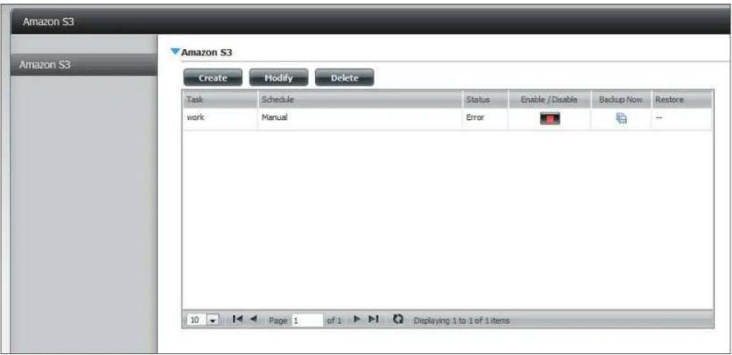
text_image
Amazon S3 Amazon S3 Amazon S3 Create Modify Delete Task Schedule Status Enable /Disable Backup Now Restore work Manual Error -- 10 Page 1 of 1 Displaying 1 to 1 of 1 itemsCreating an AWS Account
Open your web browser and type the following link for the Amazon Web Services: http://www.aws.amazon.com/s3. Then, click on the link at the top named "Create an Amazon Web Services Account". Follow the instructions to create your AWS account.
Click the "Sign Up for Amazon S3" button and follow the instructions to select the amount of desired storage and create your Amazon S3 account.
You will be issued the following keys as credentials to give you access to the account:
- Access Key ID
- Secret Access Key
Save these keys in a secure location as your ShareCenter will need them to create the backup and recovery jobs to and from the Amazon S3 Cloud Storage.
Section 4 - Configuration
Create Button
When you click the Create button, the wizard will appear and you will be able to create either a ShareCenter backup or a restore job to the Amazon S3 Cloud Storage. You can schedule the job to run once, scheduled, or manually. You will need the following configuration data to create a backup/restore job:
Step 1: Job Name Settings
Enter a 16 character name to identify the name of the backup or the restore job.
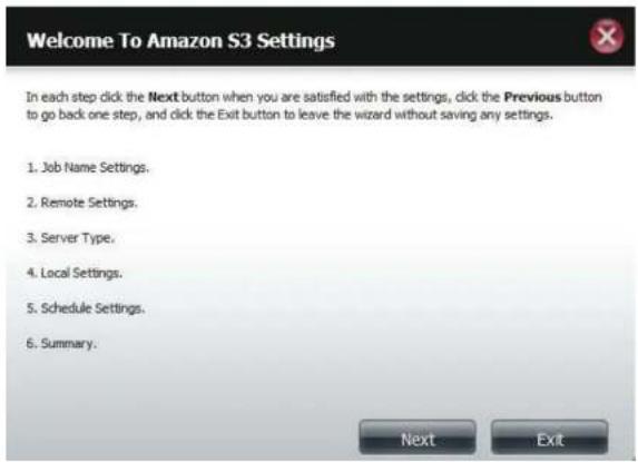
text_image
Welcome To Amazon S3 Settings In each step click the Next button when you are satisfied with the settings, click the Previous button to go back one step, and click the Exit button to leave the wizard without saving any settings. 1. Job Name Settings. 2. Remote Settings. 3. Server Type. 4. Local Settings. 5. Schedule Settings. 6. Summary. Next Exit
text_image
Step 1: Job Name Settings Input a 16 character string that identifies either the upload to cloud or download from cloud job to be created. The string cannot contain spaces and the following characters are allowed: a-2, A-2, 0-9. Job Name Job1 Previous Next ExitSection 4 - Configuration
Step 2: Remote Settings
Access Key ID: Enter your Amazon S3 assigned Access Key ID which allows your ShareCenter to access your Amazon S3 Cloud Storage.
Secret Access Key: Enter your Secret Access Key to access your Amazon S3 Cloud Storage.
Remote Path: Input a new or already existing Amazon bucket name.
Region: Select your Region from the drop-down menu.
Step 3: Server Type
Type: Select Upload or Download from the drop-down menu.
Backup Type: Use the drop-down menu and select Overwrite Existing Files, Full Backup or Incremental Backup.
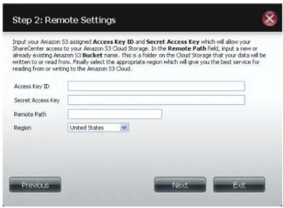
text_image
Step 2: Remote Settings Input your Amazon S3 assigned Access Key ID and Secret Access Key which will allow your ShareCenter access to your Amazon S3 Cloud Storage. In the Remote Path field, input a new or already existing Amazon S3 Bucket name. This is a folder on the Cloud Storage that your data will be written to or read from. Finally select the appropriate region which will give you the best service for reading from or writing to the Amazon S3 Cloud. Access Key ID: Secret Access Key: Remote Path: Region United States Previous Next Exit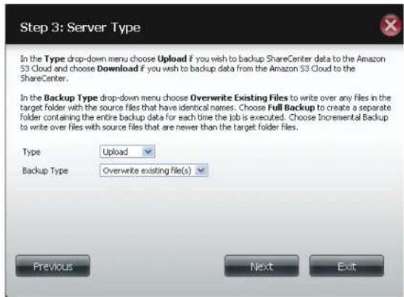
text_image
Step 3: Server Type In the Type drop-down menu choose Upload if you wish to backup ShareCenter data to the Amazon S3 Cloud and choose Download if you wish to backup data from the Amazon S3 Cloud to the ShareCenter. In the Backup Type drop-down menu choose Overwrite Existing Files to write over any files in the target folder with the source files that have identical names. Choose Full Backup to create a separate folder containing the entire backup data for each time the job is executed. Choose Incremental Backup to write over files with source files that are never than the target folder files. Type Upload Backup Type Overwrite existing file(s) Previous Next ExitSection 4 - Configuration
Step 4: Local Settings
Use the Browser button to locate the path to the ShareCenter file location to be either backed up or restored to/from the AmazonS3 Cloud.
Step 5: Schedule Settings
Select the Schedule Mode for the job to be executed. You may select Manual (now or later from the job list), Once (at a predetermined time and day), or Scheduled (a predetermined time on a daily basis).

text_image
Step 4: Local Settings In the Local_Path field input the full path name to the folder that will be either the source or target directory for the job. For e.g. Volume_1/backup_docs Local Path Browser Previous Next Exit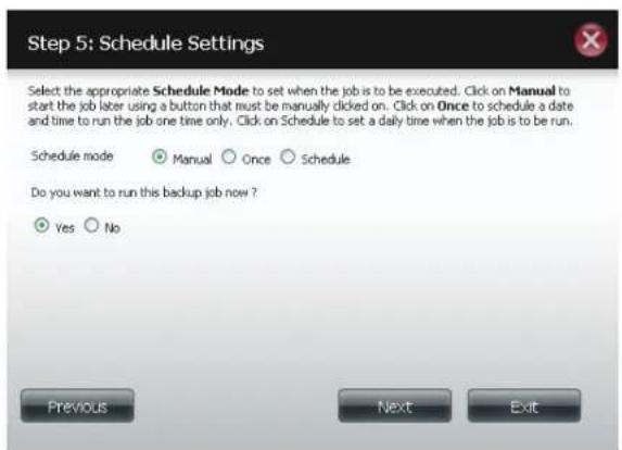
text_image
Step 5: Schedule Settings Select the appropriate Schedule Mode to set when the job is to be executed. Click on Manual to start the job later using a button that must be manually clicked on. Click on Once to schedule a date and time to run the job one time only. Click on Schedule to set a daily time when the job is to be run. Schedule mode Manual Once Schedule Do you want to run this backup job now ? Yes No Previous Next ExitModify Button
Once a job is created, the Modify button is used to change any of the settings described in the Create Button section. Click on a created job in the Amazon S3 table so that its text turns red. Then click the Modify button to edit the job settings in a wizard that appears.
Note: The Job Name cannot be modified.
Delete Button
The Delete button is used to delete any backed up or restored job listed in the Amazon S3 table. Click on a created job in the Amazon S3 table so that its text turns red. Then click the Delete button to remove the job from your ShareCenter configuration.
Enable/Disable Column
This field of the jobs controls whether the job will execute or not. If the button shows a green triangle, clicking it enables the job to function. If the button shows the red square, clicking it disables the job from executing.
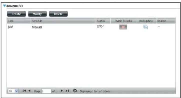
text_image
Amazon S3 Create Modify Delete Task Schedule Status Enable / Disable Backup Now Restore job1 Manual Error 10 Page 1 of 1 Displaying 1 to 1 of 1 itemsmydlink
The mydlink service offers a cloud service to DNS-320L users. Connect to the mydlink service from any location and using any operating system. If you are not connecting to the service directly from the DNS-320L, open your browser and type in www.mydlink.com. Sign into your account on the home page.

text_image
mydlink FAQ | Support | Language English▼ Share | New! Sign in to mydlink Name@example.com Password Remember me Sign in → Forgot your password? | Not Registered? What's mydlink Access Anywhere Product Family Experience mydlink See your home from anywhere With mydlink-enabled network cameras, it's simple to keep an eye on your home and everything in it from anywhere. More Details → News & Maintenance 2011/12/03 12:00 Which devices close the mydlink APP n... 2011/11/25 12:00 mydlink+ app now available for iPad ... Support & Download Setup wizard, User manual, Firmware, Quick Installation Guide & more...Global D-Link | About mydlink | Terms of Use | Privacy Policy | Contact Use Copyright©2008-2012 D-Link Corp. All rights reserved.
mydlink Verification
Check your e-mail box and click the weblink to activate mydlink account.

Activate your mydlink account
Hello
Thank you for joining mydlink.
To activate your mydlink account, please click the link below: http://sgqa.mydlink.com/activated_account/9a9e308451da51109f8c8af9bb53c1bd?lang=en
If clicking the link doesn't work, copy and paste the URL address into Internet Explorer.
After activating your account, you will be able to sign in to sqqa.mydlink.com using the e-mail address and password you provided during the signup or Installation wizard process.
If you have received this e-mail in error, please ignore this e-mail and we apologize for the inconvenience.
sqqa.mydlink.com
This e-mail message was sent from a notification-only address that cannot accept incoming e-mail. Please do not reply to this message. If you have any questions, please contact mydlink customer service at sgqa.mydlink.com/contact
Global D-Link | About mydlink | Terms of Use | Privacy Policy | Contact Us
Section 4 - Configuration
mydink is verified
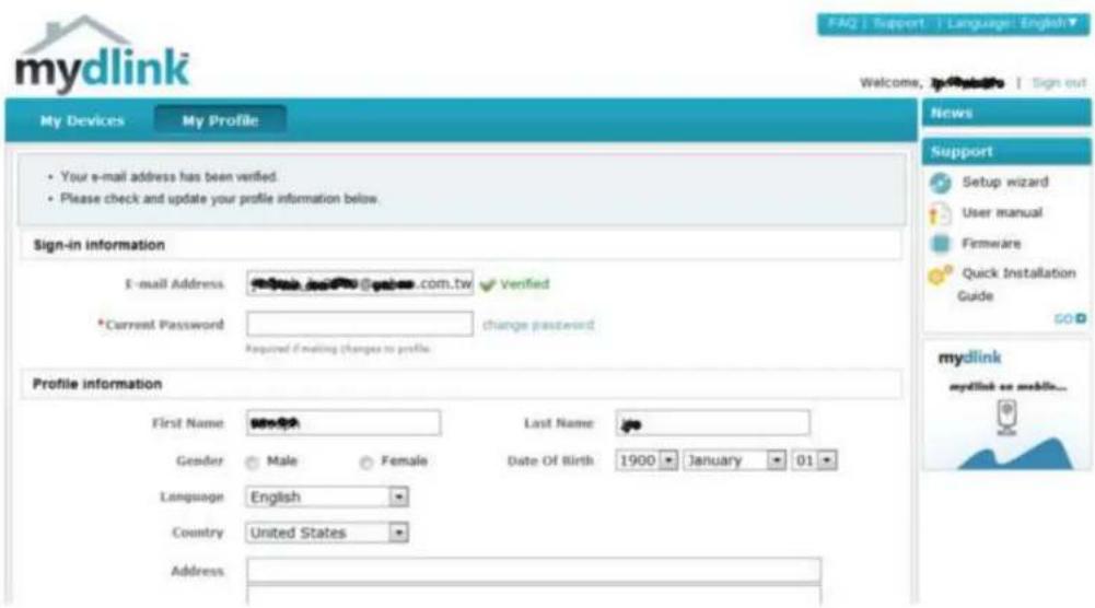
text_image
mydlink My Devices My Profile • Your e-mail address has been verified. • Please check and update your profile information below. Sign-in information E-mail Address: www.mdb.com.tw *Current Password: Verified change password Required if making changes to profile. Profile information First Name: Male Female Last Name: Date Of Birth 1900 January 01 Gender Language English Country United States Address FAQ | Support | Language | English Welcome, Sign out News Support Setup wizard User manual Firmware Quick Installation Guide mydlink mydlink or mobile...mydlink Java Runtime Machine
Once you log into your account, you will need the Java Runtime machine. The screen provides directions in order for you to download it.
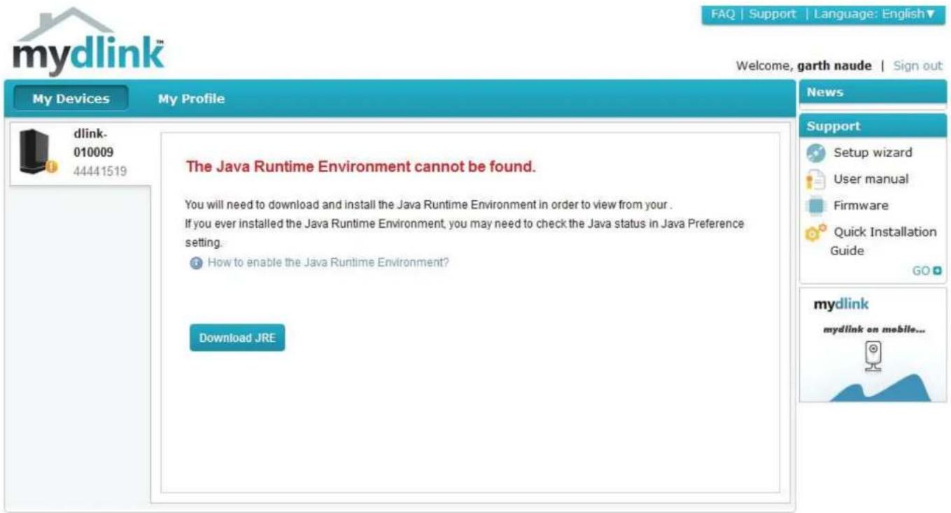
text_image
mydlink™ FAQ | Support | Language: English▼ Welcome, garth naude | Sign out My Devices My Profile dlink- 010009 44441519 The Java Runtime Environment cannot be found. You will need to download and install the Java Runtime Environment in order to view from your. If you ever installed the Java Runtime Environment, you may need to check the Java status in Java Preference setting. How to enable the Java Runtime Environment? Download JRE News Support Setup wizard User manual Firmware Quick Installation Guide GO mydlink mydlink on mobile...Global D-Link | About mydlink | Terms of Use | Privacy Policy | Contact Us Copyright©2008-2012 D-Link Corp. All rights reserved.
Section 4 - Configuration
The Java Runtime machine takes a few steps. Follow the instructions:
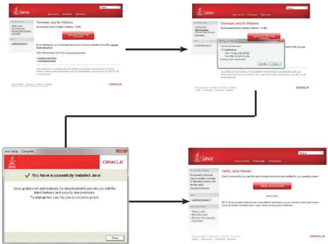
flowchart
graph TD
    A["Java Setup - Complete"] --> B["Download Java for Windows"]
    B --> C["Oracle Setup"]
    C --> D["Verifying Java Version"]
    D --> E["Final Version"]

    subgraph A
        A1["Java Setup - Complete"] --> A2["You have successfully installed Java"]
        A2 --> A3["Java Setup - Complete"]
    end

    subgraph B
        B1["Java Setup - Complete"] --> B2["Oracle Setup"]
    end

    subgraph C
        C1["Java Setup - Complete"] --> C2["Oracle Setup"]
    end

    subgraph D
        D1["Java Setup - Complete"] --> D2["Oracle Setup"]
    end

    subgraph E
        E1["Java Setup - Complete"] --> E2["Oracle Setup"]
    end

    A1 --> B1
    B1 --> C1
    C1 --> D1
    D1 --> E1

    style A fill:#f9f,stroke:#333
    style B fill:#ccf,stroke:#333
    style C fill:#cfc,stroke:#333
    style D fill:#fcc,stroke:#333
Section 4 - Configuration
After the Java Runtime machine is installed, run the mydlink application and enter the password.
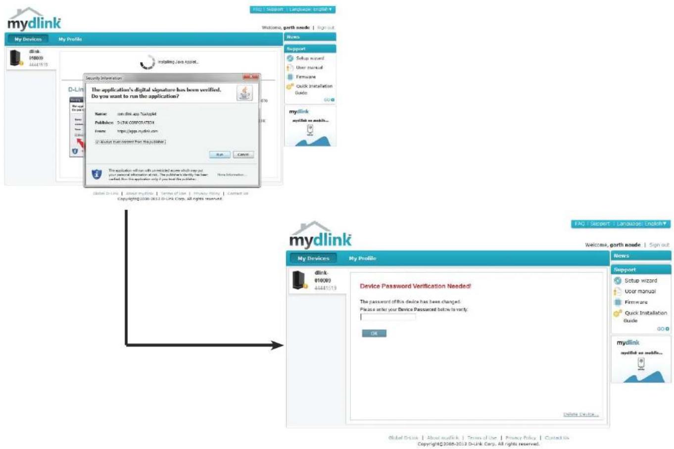
text_image
mydlink My Devices My Profile File | Support | Language | English Welcome, gorth naode | Sign out My Documents 170039 44441515 Installing Java Applet... D-Link New Product New Document Security Information The application's digital signature has been verified. Do you want to run the application? Name: com.dlink.asp.Dutaplet Publishers: 513K CORPORATION Event: https://sges.mydlink.com [ ] Mydlink your content from the publisher] Run... Cancel This application will run with un violations across which you put your personal information at all. The publication clearly has been certified. But this application only if you have the publisher... No information... Global D-Link | About mydlink | Terms of Use | Privacy Policy | Contact us Copyright©2008-2012 D-Link Corp. All rights reserved... mydlink My Profile FAQ | Support | Language | English▼ Welcome, gorth naode | Sign out My Devices My Profile dlink 010(09) 44441019 Device Password Verification Needed! The password of this device has been changed. Please enter your Device Password below to vary. OK Delete Device... News Support Setup wizard User manual Firmware Quick Installation Guide GO mydlink mydlink on mobile... Global D-Link | About mydlink | Terms of Use | Privacy Policy | Contact us Copyright©2008-2012 D-Link Corp. All rights reserved.Section 4 - Configuration
Once you are connected you can view your existing storage on the cloud and the DNS-320L. You can also upload, download files using your browser, create new folders, rename folders and delete folders.

text_image
mydlink My Devices DNS-320L 44441560 My Profile File Settings Home Optioned Downloaded None / Additions Delete Rename Volume_1 97% used (885GB of 914GB) News 2011/09/15 07:00 mydlink Server Shutdown Notificati... 2011/8/30 6:00 mydlink Server Shutdown Notificati... Support Setup wizard User manual Firmware Quick Installation Guide GO Top 5 FAQs How do I update my device's firmware in anually? Which device does t he mydlink website s upport? How do I install the mydlink lite app on my Android device? Which web browsers can I use with mydli nk? How do I sign up for a mydlink account? GO Global D-Link | About mydlink | Terms of Use | Privacy Policy | Contact Us Copyright©2008-2012 D-Link Corp. All rights reserved.Click Volume 1 to see its contents. Here you can create a New Folder, Upload and Download files, Delete and Rename files.

text_image
Mydlink My Devices My Profile DNS-320L 44441518 File Settings Home > Volume_1 > Media Contents 0% used (635WB of 290GB) Upload Download New Folder Delete Rename Name▼ Type Size Modified Date & Time [MV][SAMSUNG HD Demo] ... Video 277354 KB 2012-04-13 14:59:56 wonder girls - Nobody (MV版) ... Video 42225 KB 2012-04-13 14:59:59 Wonder Girls - NoBody (粉红) ... Video 41193 KB 2012-04-13 15:00:00 tn_1.jpg Picture 36 KB 2012-04-13 14:59:33 tn_10.jpg Picture 39 KB 2012-04-13 14:59:33 tn_11.jpg Picture 64 KB 2012-04-13 14:59:33 tn_12.jpg Picture 36 KB 2012-04-13 14:59:33 tn_2.jpg Picture 36 KB 2012-04-13 14:59:33 tn_3.jpg Picture 46 KB 2012-04-13 14:59:33 FAQ | Support | Language: English▼ Welcome, Sign out News Support Setup wizard User manual Firmware Quick Installation Guide GO + mydlink mydlink on mobile...Creating a New Folder
Click the New Folder button to create a new folder. Enter a name for the folder and click Create.
To delete a folder, click the checkbox next to the file you wish to delete. Click the Delete button. A confirmation window will appear for you to confirm the deletion. Click Delete to proceed.
To rename a file or folder, click the checkbox next to the file/folder you wish to rename. Click the Rename button. A confirmation window will appear for you to rename the file. Enter a new name and click Rename.
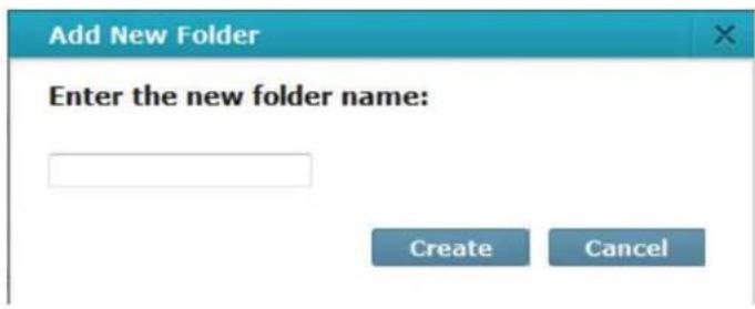
text_image
Add New Folder Enter the new folder name: Create Cancel
text_image
Delete File(s)? Do you want to delete "[MV][SAMSUNG HD Demo]Wonder Girls_Nobody_MPEG2_1080I.avi"? Delete Cancel
text_image
Rename File Enter the new file name: [MV][SAMSUNG HD Den Rename Cancelmydlink Settings Details
Under the Settings tab you are able to change all key settings directly from your browser.
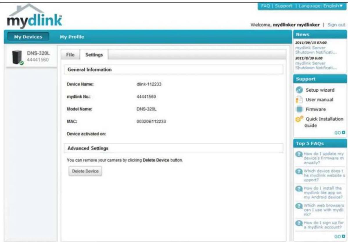
text_image
mydlink My Devices DNS-320L 44441560 My Profile File Settings General Information Device Name: dlink-112233 mydlink No:: 44441560 Model Name: DNS-320L MAC: 00320B112233 Device activated on: Advanced Settings You can remove your camera by clicking Delete Device button. Delete Device News 2011/09/15 07:00 mydlink Server Shutdown Notificati... 2011/8/30 6:00 mydlink Server Shutdown Notificati... Support Setup wizard User manual Firmware Quick Installation Guide GO Top 5 FAQs How do I update my device's firmware m anually? Which device does t he mydlink website s upport? How do I install the mydlink lite app on my Android device? Which web browsers can I use with mydli nk? How do I sign up for a mydlink account? GOGlobal D-Link | About mydlink | Terms of Use | Privacy Policy | Contact Us Copyright©2008-2012 D-Link Corp. All rights reserved.
ShareCenter NAS Status
Here you can see the online status of your ShareCenter NAS when connected to mydlink. Your online status might be one of the following:

A green checkmark indicates that your ShareCenter NAS is online and ready for use.

A yellow exclamation point indicates that your ShareCenter NAS is online, but the mydlink password has changed. You will need to enter your new mydlink password to access your ShareCenter NAS again.
A red x indicates that your ShareCenter NAS is offline and currently cannot be accessed remotely.
If your ShareCenter is offline, try the following:
- Check to make sure that the internet connection to your ShareCenter NAS is working properly.
- Try restarting your internet router.
- Check your ShareCenter NAS cable connections and make sure they are secure.
- Check to make sure that the LED on your ShareCenter NAS is lit solid blue.
If you still cannot access your ShareCenter NAS, reset your ShareCenter NAS and run the DNS-320L Setup Wizard again from the CD-ROM included in your package.
Deleting a mydlink device
Select the device you wish to delete. A warning message appears for you to verify your deletion.
Enter your admin password to delete the device. Click Delete Device to proceed. An acknowledgement message appears to confirm the deletion.
Delete Device
The following device will be deleted from your account:
Device name: DNS-320L
mydlink No.: 44441518
Device model: DNS-320L
! Warning!
- Remove the device will also remove any mydlink functions related to the device.
Please enter your password to proceed:
Password
Cancel
Delete Device
Delete Device
The following device has been successfully deleted from your mydlink account:
Device name: DNS-320L
mydlink No.: 44441518
Device model: DNS-320L
To add the device to mydlink account and enable remote access to it, please run the device's Setup Wizard again. You can download the Setup Wizard from the Support page
Done
Deleting a mydlink account
Under Profile Information, click the Delete account link at the bottom.
A warning message appears to ask you if you want to delete the account. Select No, keep it to do nothing or click Yes, delete it to delete the account.

text_image
*Correct Password Change password Featured Existing Customs to profile. Profile information First Name: Male Female Last Name: Date Of Birth 1930 January 01 Gender Language English Country United States Address City ZIP/Postal code State/Prevalence iPhone I would like to receive the latest product information from mydink services. Save Reset Delete accountDelete account
WARNING!
Are you sure you want to delete your account at mydlink? All your settings and account information will be permanently erased from mydlink website, and the deletion is irreversible.
No, keep it
Yes, delete it
Section 4 - Configuration
In order to delete the mydlink account you need to enter your password details. Enter your details and then click Confirm Delete.
Click Cancel to revert back and keep your account in tact.
The Account is deleted.
Delete account
WARNING!
Are you sure you want to delete your account at mydlink? All your settings and account information will be permanently erased from mydlink website, and the deletion is irreversible.
Please enter your mydlink password to confirm:
●●●●●●●●
Cancel
Confirm Deletion
Delete account
Account Deleted!
We are very sorry to watch you go, but now you have confirmed your departure from mydlink service, and a confirmation email is sent to your mailbox.
Thank you and we hope to see you back soon!
Exit
Knowledge Base
What is RAID?
RAID, short for Redundant Array of Independent Disks, is a combination of two or more disks with the aim of providing fault tolerance and performance improvement. There are several different levels of RAID, with each one providing a different method of sharing or distributing data amongst the drives. The DNS-320L supports Standard, JBOD, RAID 0, and RAID 1.
Standard
Standard provides a single volume for each drive.
Although performance is improved, the lack of any RAID or mirroring means that if one drive fails, all data on the volume will be lost.
JBOD
JBOD allows you to create a large virtual disk drive by concatenating two or more smaller drives together.
It offers no redundancy and limited data protection..
Section 5 - Knowledge Base
RAID 0 RAID 0 provides data striping, which spreads out blocks of data over all the drives, but does not provide data redundancy.
Although performance is improved, the lack of fault tolerance means that if one drive fails, all data in the array will be lost.
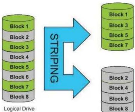
flowchart
graph TD
    A["Logical Drive"] --> B["Block 1"]
    A --> C["Block 2"]
    A --> D["Block 3"]
    A --> E["Block 4"]
    A --> F["Block 5"]
    A --> G["Block 6"]
    A --> H["Block 7"]
    A --> I["Block 8"]
    B --> J["Block 1"]
    C --> K["Block 3"]
    D --> L["Block 5"]
    E --> M["Block 7"]
    F --> N["Block 2"]
    G --> O["Block 4"]
    H --> P["Block 6"]
    I --> Q["Block 8"]
Physical Disks
RAID 1 RAID 1 provides mirroring over multiple disks, with the same read/write speed of a single disk. A RAID 1 array can only be as large as it's smallest member disk.
Because the data is stored on multiple disks, RAID 1 provides fault tolerance and protection, in addition to performance advantages.
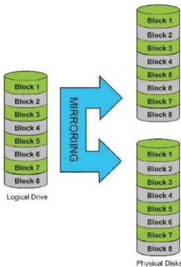
flowchart
graph TD
    A["Logical Drive"] -->|Mirroring| B["Physical Disks"]
    subgraph Block 1
        A1["Block 1"]
        A2["Block 2"]
        A3["Block 3"]
        A4["Block 4"]
        A5["Block 5"]
        A6["Block 6"]
        A7["Block 7"]
        A8["Block 8"]
    end
    subgraph Block 2
        B1["Block 1"]
        B2["Block 2"]
        B3["Block 3"]
        B4["Block 4"]
        B5["Block 5"]
        B6["Block 6"]
        B7["Block 7"]
        B8["Block 8"]
    end
    subgraph Block 3
        C1["Block 1"]
        C2["Block 2"]
        C3["Block 3"]
        C4["Block 4"]
        C5["Block 5"]
        C6["Block 6"]
        C7["Block 7"]
        C8["Block 8"]
    end
    subgraph Block 4
        D1["Block 1"]
        D2["Block 2"]
        D3["Block 3"]
        D4["Block 4"]
        D5["Block 5"]
        D6["Block 6"]
        D7["Block 7"]
        D8["Block 8"]
    end
    subgraph Block 5
        E1["Block 1"]
        E2["Block 2"]
        E3["Block 3"]
        E4["Block 4"]
        E5["Block 5"]
        E6["Block 6"]
        E7["Block 7"]
        E8["Block 8"]
    end
    subgraph Block 6
        F1["Block 1"]
        F2["Block 2"]
        F3["Block 3"]
        F4["Block 4"]
        F5["Block 5"]
        F6["Block 6"]
        F7["Block 7"]
        F8["Block 8"]
    end
    subgraph Block 7
        G1["Block 1"]
        G2["Block 2"]
        G3["Block 3"]
        G4["Block 4"]
        G5["Block 5"]
        G6["Block 6"]
        G7["Block 7"]
        G8["Block 8"]
    end
RAID Options
Here is a list of the RAID options available on the ShareCenter DNS-320L
Standard RAID - creates a single volume for one drive or more drives.
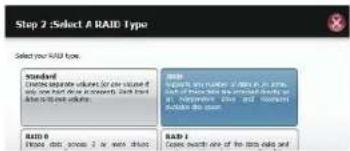
text_image
Step 2: Select A RAID Type Select your RAID type. Standard Conditions duplicate volume, for one volume if only one must be recorded. Only one should be required. RBI0 Please note, please 2 or more details. RBI1 Creates the number of links in all time units of the system, but not necessarily any other information. This is also available to the system. RBI1 Creates the number of links in all time units of the system.JBOD - allows you to create a large virtual disk drive by concatenating two or more smaller drives together. The individual hard drives that makes up a JBOD RAID can be different sizes and manufacturers. The total size of the JBOD RAID is the combined total of all the individual drives in the set.
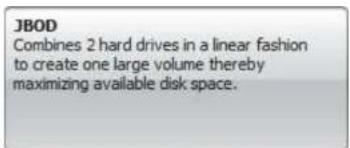
text_image
JBOD Combines 2 hard drives in a linear fashion to create one large volume thereby maximizing available disk space.RAID 0 - allows you to assign two or more disks as a striped set. Once you create the striped set, you will see it as a single disk drive. But when you write data to the RAID 0 striped set, the data will be distributed across all of the drives that make up the set. Because each disk has less to do, it takes less time to write the data. The same is true when reading data; instead of a single disk having to seek out and then send a large block of data, multiple disks each stream their part of the data stream. As a result, RAID 0 striped sets can provide a dynamic increase in disk performance.

text_image
RAID 0 Stripes data across 2 or more drives increasing performance.RAID 1 - allows you to assign two disks as a mirrored set. Once you create the mirrored set, you will see it as a single disk drive. But when you write data to the mirrored set, it will duplicate the data across all members of the set. This ensures that your data is protected against loss if any hard drive in the RAID 1 set fails. In fact, as long as any single member of the set remains functional, you will continue to operate normally, with complete access to your data.
RAID 1 Copies exactly one of the data disks and produces a mirrored copy on another disk.
UPS Connectivity
The DNS-320L supports USB UPS, giving users the ability to share the UPS on their local network and protect from an abnormal shutdown due to a power failure. Connect a UPS to the USB port on the back of the ShareCenter ^® .
Standalone and Network Master Mode:
Log into the DNS-320L.
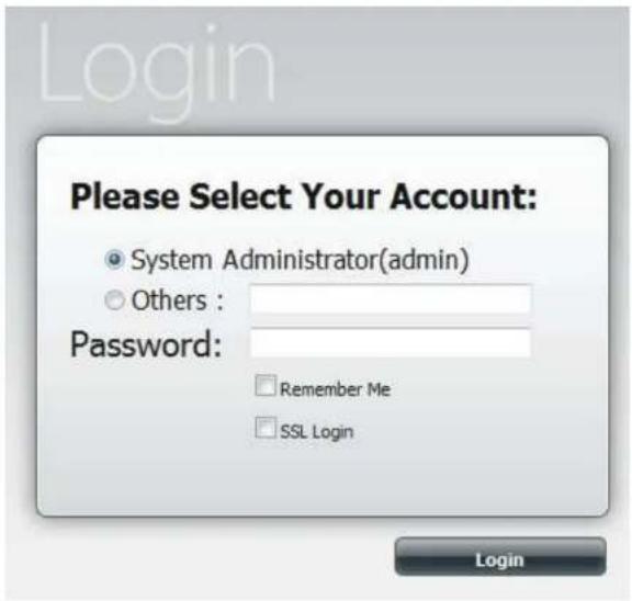
text_image
Login Please Select Your Account: System Administrator(admin) Others : Password: Remember Me SSL Login LoginSection 5 - Knowledge Base
Click Management.

text_image
ShareCenter Name Applications Management Sales Excel Sales Manager Sales Report Sales Review Sales Print Sales Web Change Status Recent ActivitiesClick System Management and then USB Devices.
Click the blue arrow next to UPS Settings. There are two modes - Standalone and Master.
Select Standalone to use the UPS only on the DNS-320L or select Master to share the UPS with the network UPS slaves.
The UPS Status screen shows the mode, manufacturer, product type, battery charge meter, and status.

text_image
ShareCenter® System App Store Management System Management System Management System Management System Management System Management System Management System Management System Management System Management System Management System Management System Management System Management System Management System Management System Management System Management System Management System Management System Management System Management System Management System Management System Management System Management System Management System Management System Management System Management System Management System Management System Management System Management System ManagementSection 5 - Knowledge Base
Under Mode, select Master from the drop-down list and then click Add.
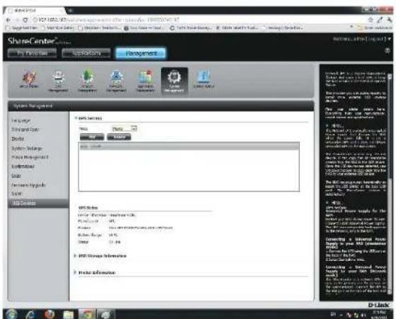
Enter the IP address of the other UPS slave on the network.
Click the + button to add more IP addresses.
Make sure the DNS-320L and the UPS slaves are on the same physical network.
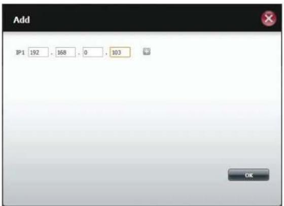
text_image
Add IP1 192 , 168 , 0 , 103 OKSection 5 - Knowledge Base
Once you have entered an IP address, the system will check its database for IP address records.

text_image
Add Waiting for LPS Settings ready and start to execute.The UPS Settings table will display the IP address(es) you added.
Your DNS-320L is now setup as the network master to notify the network slaves about critical power status.
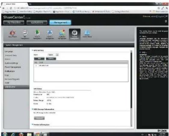
text_image
ShareCenter My Properties Settings Management System Management Language Current Data History Custom Settings Point Process Parameters Map User Configuration SUE 3D Server SME Network Name: SME Network SME Region: SME Region SME Region: SME Region SME Region: SME Region SME Region: SME Region SME Region: SME Region SME Region: SME Region SME Region: SME Region SME Region: SME Region SME Region: SME Region SME Region: SME Region SME Region: SME Region SME Region: SME Region SME Region: SME Region SME Regions: SME Regions: SME Regions: SME Regions: SME Regions: SME Regions: SME Regions: SME Regions: SME Regions: SME Regions: SME Regions: SME Regions: SME Regions: SME Regions: SME Regions: SME Regions: SME Regions: SME Regions: SME Regions: SME Regions: SME Regions: SME Regions: SME Regions: SME Regions: SME Regions: SME Regions:Deleting a UPS Slave
Under Management > System Management > USB Devices > UPS Setting, select the IP address. Your selection will turn red.
Click Delete.
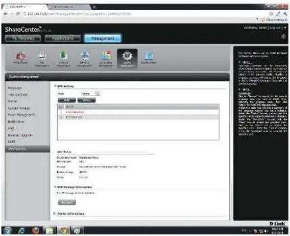
text_image
ShareCenter AS FINANCE Applications Managers Edit Manager Language New and New Block System Settings New Management Marketing Help Personal Signal SaaS SaaS Options MDS Settings Name Name URL URL URL URL URL URL URL URL URL URL URL URL URL URL URL URL URL URL URL URL URL URL URL URL URL URL URL URL URL URL URL URL URL URL URL URL URL URL URL URL URL URL URL URL URL URL URL URL URL URL AML Setup Description: Software/Services. Application: Web Services (http://www.elsevier.com) Order Code: 100% Order Size: 25 px. USB Storage Information: File Region: Web Services (http://www.elsevier.com) Search... Enter InformationThe DNS-320L will process your request.
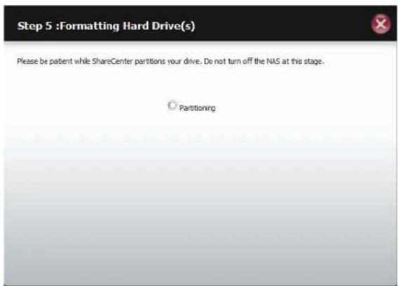
text_image
Step 5 : Formatting Hard Drive(s) Please be patent while ShareCenter partitions your drive. Do not turn off the NAS at this stage. PartitioningSection 5 - Knowledge Base
The IP address will no longer be listed in the table.
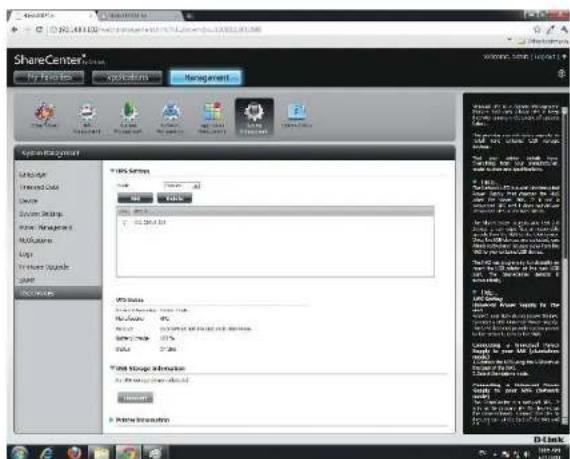
text_image
ShareCenter My Files Applications Management Operating System System Fixed Data Service System Settings User Management Modulation Loop User Source Size Description YIDS Settings Model: 10.000 GB Type: Fixed Data Value: 25.000 GB MOS Status No. of data available in this system. Data type: 10.000 GB Data range: 10.000 GB Total Usage Information Any data available in this system. Name: 10.000 GB More Information DiskUSB Print Server
The device features a built-in USB print server, giving users the ability to share a printer on their local network. Connect a USB printer to the USB port on the back of the device. It is important to ensure that any of the printer manufacturer's drivers are already installed or available on any computer you want to print from.
Note: Only the print function is supported. The device does not support the copy and scan functions of Multi-Function Printers.
To add a printer, connect your printer via USB cable to the USB port of your device:
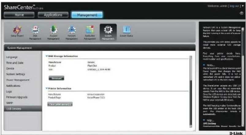
text_image
ShareCenter™ Home Applications Management Setup Wizard Disk Management Account Management Provider Management Application Management System Management System Status System Management Language Time and Date Device System Settings Power Management Modulations Logs Hardware Upgrade SNAP USB Devices USB Storage Information Manufacture Generate Product Plan/Ok Size US$5001_0.014-0.08 General Printer Information Manufacturer Innovation Operator Product Type New/Power 521 Clear print security System: LPS is a System Management System: LPS is about USfor less than a50 per unit, but only a $50 per unit in the order of a power failure. This provides you with some options to retail more external USB storage devices. Find your prior details here. Reporting from your manufacture, which number and specifications. • Make... The system will be about Software Power Supply that changes the HAC when the power link is not an external USB and it does not alter reduced on its HAC name. The system contains any USB to store. It can use files on external options from the HAC to the USB device. Once the USB devices are directed, we Windows��3697 Service Store from the HAC to your internal OS device. The last version plus functionality is new the USB printer at the back user port. The schematic includes an automatic. • Help... USB Setup D-LinkThe printer should appear in the USB Devices menu of the System Management icon.
Section 5 - Knowledge Base
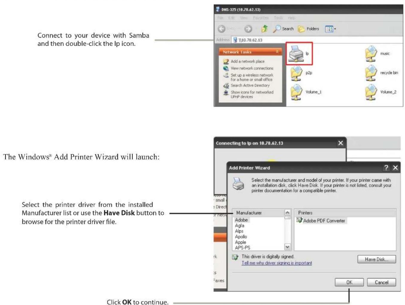
text_image
DNS-325 (10.78.62.13) File Edit View Favorites Tools help Address \\10.78.62.13 Connect to your device with Samba and then double-click the Ip icon. Network Tasks Ip music Add a network place p2p recycle bin View network connections p2p Set up a wireless network for a home or small office Search Active Directory Volume_1 Show icons for networked UPnP devices Volume_2 The Windows® Add Printer Wizard will launch: Select the printer driver from the installed Manufacturer list or use the Have Disk button to browse for the printer driver file. Connecting to Ip on 10.78.62.13 Add Printer Wizard Select the manufacturer and model of your printer. If your printer came with an installation disk, click Have Disk. If your printer is not listed, consult your printer documentation for a compatible printer. Manufacturer Adobe Agla Alps Apollo Apple APS-PS Printers Adobe PDF Converter This driver is digitally signed. Tell me why driver signing is important Have Disk... OK Cancel Click OK to continue.Section 5 - Knowledge Base

text_image
Install From Disk Insert the manufacturer's installation disk, and then make sure that the correct drive is selected below. OK Cancel Copy manufacturer's files from: E:\Phaser 3121\GDI_DRV\AddPrint\WinXP Browse...Once you have selected the proper driver as shown in the browse list then click OK to install the printer.
The printer is now installed and the printer queue will appear.