
DVS-310-1 - Server D-LINK - Free user manual and instructions
Find the device manual for free DVS-310-1 D-LINK in PDF.


| Product Type | Network Video Server |
| Brand | D-Link |
| Model | DVS-310-1 |
| Dimensions (WxDxH) | 280 x 180 x 44 mm |
| Weight | 2.5 kg |
| Power Supply | 12 V DC, 5 A |
| Power Consumption | 20 W (max) |
| Form Factor | 1U rackmount |
| Main Functions | H.264 video encoding, RTSP stream, network streaming, remote management |
| Maintenance and Cleaning | Dust with a soft, dry cloth. Do not use liquid or abrasive products. |
| Safety | Install in a ventilated area, avoid electrical overloads, disconnect before any intervention. |
| Available Spare Parts | External power supply, Ethernet cable, mounting screws |
| Repairability | Repairable by a qualified technician. See the manual for disassembly procedures. |
| Operating Temperature | 0 °C to 40 °C |
| Operating Humidity | 10% to 80% (non-condensing) |
| Certifications | CE, FCC |
Frequently Asked Questions - DVS-310-1 D-LINK
User questions about DVS-310-1 D-LINK
0 question about this device. Answer the ones you know or ask your own.
Ask a new question about this device
Download the instructions for your Server in PDF format for free! Find your manual DVS-310-1 - D-LINK and take your electronic device back in hand. On this page are published all the documents necessary for the use of your device. DVS-310-1 by D-LINK.
USER MANUAL DVS-310-1 D-LINK
Quick Installation Guide+
If any of the items are missing, please contact your reseller.
natural_image
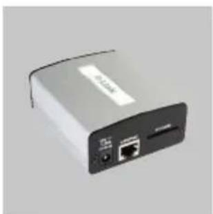
Exterior view of a gray electronic device with ports and an Ethernet port (no visible text or symbols)DVS-310-1 Video Encoder
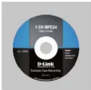
CD-ROM with Manual and Setup Wizard
natural_image
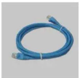
Blue cable with connectors and connectors, no visible text or symbolsEthernet (CAT5 UTP) Cable

natural_image
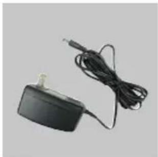
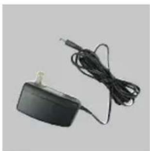
Black electronic device with attached cable and connector (no visible text or symbols)12V Power Adapter

natural_image
Black metal bracket with four holes and three screws, no text or symbols visibleMounting Bracket and Screws

Note :
Using a power supply with a different voltage rating will damage and void the warranty of this product.
Hardware Installation
Note: The following installation instructions assume that an analog video camera is installed and providing a signal. If necessary, please consult your camera manufacturer's user manual for information on how to set up your analog camera.
Connect the Video Cable
Connect the video cable from the camera to the VIDEO IN port of the video encoder.
Once the cable has been connected, rotate the BNC connector clockwise so that the cable locks into place.
Connect the Power Supply
Attach the external power supply to the DC power socket (labeled 12V 1.25A) and plug the two-pronged adapter into an AC power outlet. Alternatively, the DVS-310-1 may be powered via PoE Ethernet cable. In this case, the supplied power adapter should not be connected.
When the DVS-310-1 is receiving power, the green power LED will be lit.
Connect the Ethernet Cable
Connect a CAT5 Ethernet cable to the LAN port of the Video Encoder. Connect the opposite end of the CAT5 cable to an active network device such as a hub, switch, or router.
Insert an SD Card (Optional)
Insert an SD card with the gold contacts of the card facing upwards. Push the card into the slot until you feel it click into place.
Connect Additional Peripheral Devices (Optional)
If desired, you may also connect audio equipment such as a microphone or speaker to the AUDIO IN and AUDIO OUT ports respectively. DI/DO devices and PTZ controls may also be connected.

Troubleshooting
1. Why is the Power LED not lighting up?
The power supply used might be at fault. Confirm that you are using the provided power supply, which is DC 12V, for the Video Encoder. Also verify that the power supply is securely connected. If the device is functioning but the LED is not illuminated, the LED may be disabled. Open the firewall configuration page and click MAINTENANCE. At the bottom of the page, there will be an option to turn on or turn off the LED.
2. Why does the Video Encoder work locally but not remotely?
This might be caused by firewall protection. Check with your system administrator to see if you are behind a firewall. The firewall may need to have some settings changed in order for the Video Encoder to be accessible outside your LAN. Make sure that the Video Encoder is not conflicting with any Web server you may have running on your network. The default router setting might be another possible reason. Check that the configuration of your router's settings allow the video encoder to be accessed outside your local LAN.
3. Why are no images available through the Web browser?
ActiveX controls might be disabled within Internet Explorer. Check that ActiveX has been enabled in the Internet Options menu. You may also need to change the security settings on your browser to allow the ActiveX plug-in to be installed. If you are using a version of Internet Explorer before version 6.0, you will need to upgrade Internet Explorer in order to view the streaming video transmitted by the video encoder.
(For further troubleshooting, please refer to the User manual on the CD ROM.)
Technical Support
United Kingdom (Mon-Fri)
Home Wireless/Broadband 0871 873 3000 (9.00am–06.00pm, Sat 10.00am–02.00pm) Managed, Smart, & Wireless Switches, or Firewalls 0871 873 0909 (09.00am – 05.30pm) (BT 10ppm, other carriers may vary.)
Ireland (Mon-Fri)
All Products 1890 886 899 (09.00am-06.00pm, Sat 10.00am-02.00pm) €0.05ppm peak, €0.045ppm off peak Times
Internet
http://www.dlink.co.uk
ftp://ftp.dlink.co.uk
Notes
natural_image
Exterior view of a gray electronic device with ports and a label (no readable text or symbols beyond branding)DVS-310-1
Video Encoder

natural_image
Blue cable with connectors and connectors, no visible text or symbolsEthernet-Kabel (CAT5 UTP)

natural_image
Black electronic device with attached cable and power plug (no visible text or symbols)natural_image
Black metal bracket with multiple holes and four screws, no text or symbols visiblenatural_image
Hand inserting a USB into a device (no visible text or symbols)
natural_image
Exterior view of a silver electronic device with connected ports and cables (no visible text or symbols)
natural_image
Hand inserting a USB into a network device (no visible text or symbols)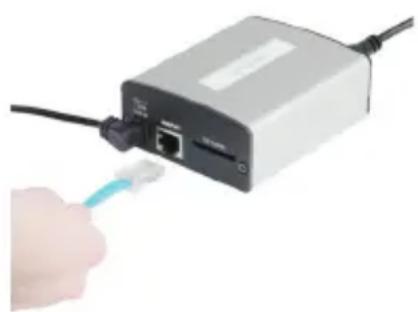
natural_image
Hand inserting a USB cable into a network device (no visible text or symbols)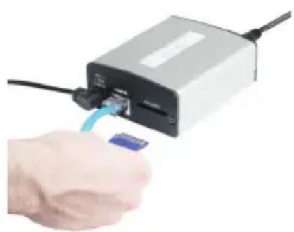
natural_image
Hand inserting a small card into a device with a blue cable (no visible text or symbols)Fehlerbehebung
natural_image
Exterior view of a gray electronic device with ports and a label (no readable text or symbols beyond the label)DVS-310-1
Video Encoder
natural_image
Blue cable with connectors and connectors, no visible text or symbolsCâble Ethernet (CAT5 UTP)
natural_image
Black electronic device with attached cable and power plug (no visible text or symbols)natural_image
Black metal bracket with four holes and three screws, no text or symbols visibleAssistance technique
natural_image
Exterior view of a silver wireless router device (no visible text or symbols)DVS-310-1
Video Encoder

natural_image
Blue cable with connectors and connectors, no visible text or symbolsCable Ethernet (CAT5 UTP)

natural_image
Black electronic device with attached cable and power plug (no visible text or symbols)natural_image
Black metal bracket with multiple holes and four screws, no text or symbols visiblenatural_image
Step-by-step installation of a USB device into a terminal block, showing cable routing and port connection (no text or symbols visible)natural_image
Exterior view of a gray electronic device with ports and a label (no readable text or symbols beyond branding)DVS-310-1 Video Encoder

natural_image
Blue cable with connectors, no visible text or symbolsCavo Ethernet (UTP CAT5)
natural_image
Black electronic device with attached cable and antenna, no visible text or symbolsAlimentatore 12 V

natural_image
Black metal bracket with multiple holes and three screws, no text or symbols visiblenatural_image
Step-by-step diagram showing hand inserting a USB into an electronic device, with no visible text or symbols.


- Note :
- Hardware Installation
- Connect the Video Cable
- Connect the Power Supply
- Connect the Ethernet Cable
- Insert an SD Card (Optional)
- Connect Additional Peripheral Devices (Optional)
- Troubleshooting
- Why is the Power LED not lighting up?
- Why does the Video Encoder work locally but not remotely?
- Why are no images available through the Web browser?
- Technical Support
- Notes
- Fehlerbehebung
- Assistance technique
Brand : D-LINK
Model : DVS-310-1
Category : Server