
DSN-6120 - Server D-LINK - Free user manual and instructions
Find the device manual for free DSN-6120 D-LINK in PDF.


| Product Type | 12-bay 2U Rackmount Server |
| Form Factor | 2U Rackmount |
| Chassis Dimensions (H x W x D) | 88 mm x 482 mm x 700 mm (3.5 x 19.0 x 27.6 in) |
| Weight | 20 kg (44.1 lbs) fully loaded |
| Drive Bays | 12 x 3.5" SAS/SATA hot-swappable |
| Processor | Dual Intel Xeon Scalable (customizable) |
| Memory | DDR4 ECC RDIMM, up to 512 GB |
| Storage Controller | Hardware RAID (RAID 0/1/5/6/10) |
| Network Interface | 2 x 10 Gigabit Ethernet + 2 x Gigabit Ethernet |
| Power Supply | Dual redundant hot-swappable 800W PSU |
| Power Consumption | Typical 300W, max 500W |
| Cooling | 4 x hot-swappable system fans |
| Management | Dedicated IPMI/BMC with web interface |
| Operating Temperature | 0°C to 40°C (32°F to 104°F) |
| Storage Temperature | -40°C to 70°C (-40°F to 158°F) |
| Relative Humidity | 10% to 85% non-condensing (operating) |
| Key Functions | High-density storage, virtualization, backup server |
| Maintenance | Replace failed drives/fans without powering off; dust filters clean quarterly |
| Safety | Meet UL, CE, FCC Class A standards; install in well-ventilated rack |
| Spare Parts & Repairability | PSU, fan modules, drive trays, RAID controller replaceable by user |
Frequently Asked Questions - DSN-6120 D-LINK
User questions about DSN-6120 D-LINK
0 question about this device. Answer the ones you know or ask your own.
Ask a new question about this device
Download the instructions for your Server in PDF format for free! Find your manual DSN-6120 - D-LINK and take your electronic device back in hand. On this page are published all the documents necessary for the use of your device. DSN-6120 by D-LINK.
USER MANUAL DSN-6120 D-LINK
natural_image
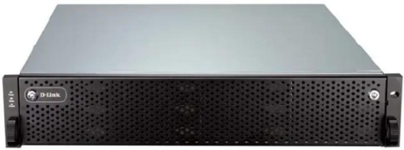
Front view of a black D-Link server rack unit (no visible text or labels on the device body)D-Link iSCSI IP SAN storage
GbE iSCSI to SATA II / SAS
RAID IP SAN storage
DSN-6110 & DSN-6120
User Manual
Version 1.0
Preface
Copyright
Copyright@2011, D-Link Corporation. All rights reserved. No part of this manual may be reproduced or transmitted without written permission from D-Link corporation.
Trademarks
All products and trade names used in this manual are trademarks or registered trademarks of their respective companies.
About this manual
This manual is the introduction of D-Link DSN-61x0 IP SAN storage and it aims to help users know the operations of the disk array system easily. Information contained in this manual has been reviewed for accuracy, but not for product warranty because of the various environments / OS / settings. Information and specification herein are subject to change without notice. For any update information, please visit www.dlink.com.
Model comparison
DSN-6100 series adopt 2U12 form factor for all models. DSN-61x0 IP SAN storages stand for the following models.
DSN-6120: Dual controllers.
DSN-6110: Single controller, can be upgradable to dual mode.
The dual controller specific functions such as dual-active, cache mirroring, flexible RG ownership management, management port seamless take-over, no system down time, and etc are not available in DSN-6110.

Caution
Do not attempt to service, change, disassemble or upgrade the equipment's components by yourself. Doing so may violate your warranty and expose you to electric shock. Refer all servicing to authorized service personnel. Please always follow the instructions in this user's manual.
Table of Contents
Chapter 1 Overview 6
1.1 Features....6
1.1.1 Highlights....7
1.2 RAID concepts 8
1.2.1 Terminology....8
1.2.2 RAID levels....10
1.2.3 Volume relationship....11
1.3 iSCSI concepts....11
1.4 IP SAN storage specifications ....13
1.4.1 Technical specifications....13
1.4.2 FCC and CE statements....16
Chapter 2 Installation....18
2.1 Package contents....18
2.2 Before installation....18
2.3 Enclosure 18
2.3.1 Front view....18
2.3.2 Front LED lights 19
2.3.3 Install drives....20
2.3.4 Rear view....21
2.4 Install battery backup module 23
2.5 Deployment....25
Chapter 3 Quick setup.... 27
3.1 Management interfaces 27
3.1.1 Serial console....27
3.1.2 Remote control....27
3.1.3 Web UI 27
3.2 How to use the system quickly 30
3.2.1 Quick installation....30
3.2.2 Volume creation wizard....32
Chapter 4 Configuration 35
4.1 Web UI management interface hierarchy 35
4.2 System configuration....36
4.2.1 System setting 36
4.2.2 Network setting....37
4.2.3 Login setting 37
4.2.4 Mail setting....38
4.2.5 Notification setting....39
4.3 iSCSI configuration 41
4.3.1 NIC....41
4.3.2 Entity property 44
4.3.3 Node 44
4.3.4 Session....47
4.3.5 CHAP account 48
4.4 Volume configuration....49
4.4.1 Physical disk....49
4.4.2 RAID group 53
4.4.3 Virtual disk....56
4.4.4 Snapshot 61
4.4.5 Logical unit....63
4.4.6 Example 65
4.5 Enclosure management 69
4.5.1 Hardware monitor....70
4.5.2 UPS 71
4.5.3 SES....73
4.5.4 Hard drive S.M.A.R.T. 73
4.6 System maintenance....74
4.6.1 System information....74
4.6.2 Event log....75
4.6.3 Upgrade 77
4.6.4 Firmware synchronization....77
4.6.5 Reset to factory default....78
4.6.6 Import and export....78
4.6.7 Reboot and shutdown....79
4.7 Home/Logout/Mute....79
4.7.1 Home 79
4.7.2 Logout....79
4.7.3 Mute....79
Chapter 5 Advanced operations....80
5.1 Volume rebuild....80
5.2 RG migration....82
5.3 VD extension....83
5.4 Snapshot....84
5.4.1 Create snapshot volume....85
5.4.2 Auto snapshot....86
5.4.3 Rollback....87
5.4.4 Snapshot constraint 87
5.5 Disk roaming....89
5.6 VD clone 90
5.7 SAS JBOD expansion....97
5.7.1 Connecting JBOD 97
5.7.2 Upgrade firmware of JBOD 97
5.8 MPIO and MC/S 98
5.9 Trunking and LACP 100
5.10 Dual controllers (only for DSN-6120)....101
5.10.1 Perform I/O....101
5.10.2 Ownership....102
5.10.3 Controller status....103
5.11 Replication 104
5.12 VLAN....114
Chapter 6 Troubleshooting 117
6.1 System buzzer....117
6.2 Event notifications 117
A. Certification list ....123
B. Microsoft iSCSI initiator....126
C. From single controller to Dual controller 132
Chapter 1 Overview
1.1 Features
D-Link DSN-6000 series IP SAN storage provides non-stop service with a high degree of fault tolerance by using D-Link RAID technology and advanced array management features.
DSN-6110/6120 IP SAN storage connects to the host system by iSCSI interface. It can be configured to numerous RAID level. The IP SAN storage provides reliable data protection for servers by using RAID 6. The RAID 6 allows two HDD failures without any impact on the existing data. Data can be recovered from the existing data and parity drives. (Data can be recovered from the rest drives.)
natural_image
Front view of a D-Link server rack unit with ventilation grilles and drive bays (no visible text or symbols)Figure 1.1.1 (DSN-6110/6120)
Snapshot-on-the-box is a fully usable copy of a defined collection of data that contains an image of the data as it appeared at the point in time, which means a point-in-time data replication. It provides consistent and instant copies of data volumes without any system downtime. Snapshot-on-the-box can keep up to 32 snapshots for one logical volume. Rollback feature is provided for restoring the previous-snapshot data easily while continuously using the volume for further data access. The data access which includes read / write is working as usual without any impact to end users. The "on-the-box" implies that it does not require any proprietary agents installed at host side. The snapshot is taken at target side. It will not consume any host CPU time thus the server is dedicated to the specific or other application. The snapshot copies can be taken manually or by schedule every hour or every day, depends on the modification.
D-Link IP SAN storage is the most cost-effective disk array system with completely integrated high-performance and data-protection capabilities which meet or exceed the highest industry standards, and the best data solution for small / medium business (SMB) and enterprise users.
1.1.1 Highlights
• D-Link DSN-6110/ 6120 feature highlights
| Host Interface | 8 x iSCSI GbE ports (DSN-6120)4 x iSCSI GbE ports (DSN-6110) |
| Drive Interface | 12 x SAS or SATA II |
| RAID Controllers | Single controller, can be upgradable to dual (DSN-6110)Dual-active RAID controllers (DSN-6120) |
| Scalability SAS | JBOD expansion port |
| Green Auto disk | spin-downAdvanced cooling |
| RAID Level RAID | 0, 1, 0+1, 3, 5, 6, 10, 30, 50, 60 and JBODN-way mirror |
| Compatibility | Support multiple OSes, applications, iSCSI HBA, software initiators, and etc. |
| Virtualization | VMWare, Hyper-V, Citrix |
| Data Protection | Snapshot (Read only and Writeable), Storage base Replication |
| Connection Availability | Load balancing and failover support on the iSCSI GbE ports |
| Dimension (W x D x H) | 442.8 x 500.6 x 88.0 (mm) |
| Power Supply | 2 x 500W PSU |
| Cache Protection | Hot pluggable battery backup module |
| Fan Redundant |
1.2 RAID concepts
RAID is the abbreviation of “Redundant Array of Independent Disks”. The basic idea of RAID is to combine multiple drives together to form one large logical drive. This RAID drive obtains performance, capacity and reliability than a single drive. The operating system detects the RAID drive as a single storage device.
1.2.1 Terminology
The document uses the following terms:
• Part 1: Common
| RAID | Redundant Array of Independent Disks. There are different RAID levels with different degree of data protection, data availability, and performance to host environment. |
| PD | The Physical Disk belongs to the member disk of one specific RAID group. |
| RG | Raid Group. A collection of removable media. One RG consists of a set of VDs and owns one RAID level attribute. |
| VD | Virtual Disk. Each RD could be divided into several VDs. The VDs from one RG have the same RAID level, but may have different volume capacity. |
| LUN | Logical Unit Number. A logical unit number (LUN) is a unique identifier which enables it to differentiate among separate devices (each one is a logical unit). |
| GUI | Graphic User Interface. |
| RAID cell | When creating a RAID group with a compound RAID level, such as 10, 30, 50 and 60, this field indicates the number of subgroups in the RAID group. For example, 8 disks can be grouped into a RAID group of RAID 10 with 2 cells, 4 cells. In the 2-cell case, PD {0, 1, 2, 3} forms one RAID 1 subgroup and PD {4, 5, 6, 7} forms another RAID 1 subgroup. In the 4-cells, the 4 subgroups are PD {0, 1}, PD {2, 3}, PD {4, 5} and PD {6,7}. |
| WT | Write-Through cache-write policy. A caching technique in which the completion of a write request is not signaled until data is safely stored in non-volatile media. Each data is synchronized inboth data cache and accessed physical disks. |
| WB | Write-Back cache-write policy. A caching technique in which the completion of a write request is signaled as soon as the data in cache and actual writing to non-volatile media occurs at a later time. It speeds up system write performance but needs to bear the risk where data may be inconsistent between data cache and the physical disks in one short time interval. |
| RO | Set the volume to be Read-Only. |
| DS | Dedicated Spare disks. The spare disks are only used by one specific RG. Others could not use these dedicated spare disks for any rebuilding purpose. |
| GS | Global Spare disks. GS is shared for rebuilding purpose. If some RGs need to use the global spare disks for rebuilding, they could get the spare disks out from the common spare disks pool for such requirement. |
| DG | DeGraded mode. Not all of the array's member disks are functioning, but the array is able to respond to application read and write requests to its virtual disks. |
| SCSI | Small Computer Systems Interface. |
| SAS | Serial Attached SCSI. |
| S.M.A.R.T. | Self-Monitoring Analysis and Reporting Technology. |
| WWN | World Wide Name. |
| HBA | Host Bus Adapter. |
| SES | SCSI Enclosure Services. |
| NIC | Network Interface Card. |
| BBM | Battery Backup Module |
- Part 2: iSCSI
| iSCSI | Internet Small Computer Systems Interface. |
| LACP | Link Aggregation Control Protocol. |
| MPI O | Multi-Path Input/Output. |
| MC/ S | Multiple Connections per Session |
| MTU | Maximum Transmission Unit. |
| CHAP | Challenge Handshake Authentication Protocol. An optional security mechanism to control access to an iSCSI storage system over the iSCSI data ports. |
| iSNS | Internet Storage Name Service. |
• Part 3: Dual controller
| SBB | Storage Bridge Bay. The objective of the Storage Bridge Bay Working Group (SBB) is to create a specification that defines mechanical, electrical and low-level enclosure management requirements for an enclosure controller slot that will support a variety of storage controllers from a variety of independent hardware vendors (“IHVs”) and system vendors. |
1.2.2 RAID levels
There are different RAID levels with different degree of data protection, data availability, and performance to host environment. The description of RAID levels are on the following:
| RAID 0 | Disk striping. RAID 0 needs at least one hard drive. |
| RAID 1 | Disk mirroring over two disks. RAID 1 needs at least two hard drives. |
| N-way mirror | Extension to RAID 1 level. It has N copies of the disk. |
| RAID 3 | Striping with parity on the dedicated disk. RAID 3 needs at least three hard drives. |
| RAID 5 | Striping with interspersed parity over the member disks. RAID 3 needs at least three hard drives. |
| RAID 6 | 2-dimensional parity protection over the member disks. RAID 6 needs at least four hard drives. |
| RAID 0+1 | Mirroring of the member RAID 0 volumes. RAID 0+1 needs at least four hard drives. |
| RAID 10 | Striping over the member RAID 1 volumes. RAID 10 need least four hard drives. |
| RAID 30 | Striping over the member RAID 3 volumes. RAID 30 needs at least six hard drives. |
| RAID 50 | Striping over the member RAID 5 volumes. RAID 50 needs at least six hard drives. |
| RAID 60 | Striping over the member RAID 6 volumes. RAID 60 needs at least eight hard drives. |
| JBOD | The abbreviation of “Just a Bunch Of Disks”. JBOD needs at least one hard drive. |
1.2.3 Volume relationship
The below graphic describes the relationship of RAID components. One RG (RAID group) consists of a set of VDs (Virtual Disk) and owns one RAID level attribute. Each RG can be divided into several VDs. The VDs in one RG share the same RAID level, but may have different volume capacity. All VDs share the CV (Cache Volume) to execute the data transaction. LUN (Logical Unit Number) is an unique identifier, in which users can access through SCSI commands.
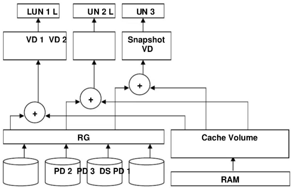
flowchart
graph TD
    A["LUN 1 L"] --> B["VD 1 VD 2"]
    C["UN 2 L"] --> D["+"]
    E["UN 3"] --> F["Snapshot VD"]
    B --> G["+"]
    D --> G
    F --> G
    G --> H["RG"]
    H --> I["PD 2 PD 3 DS PD 1"]
    H --> J["Cache Volume"]
    J --> K["RAM"]
    style A fill:#f9f,stroke:#333
    style C fill:#f9f,stroke:#333
    style E fill:#f9f,stroke:#333
    style G fill:#ccf,stroke:#333
    style H fill:#cfc,stroke:#333
    style J fill:#fcc,stroke:#333
    style I fill:#fcf,stroke:#333
    style K fill:#cff,stroke:#333
Figure 1.2.3.1
1.3 iSCSI concepts
iSCSI (Internet SCSI) is a protocol which encapsulates SCSI (Small Computer System Interface) commands and data in TCP/IP packets for linking storage devices with servers over common IP infrastructures. iSCSI provides high performance SANs over standard IP networks like LAN, WAN or the Internet.
IP SANs are true SANs (Storage Area Networks) which allow several servers to attach to an infinite number of storage volumes by using iSCSI over TCP/IP networks. IP SANs can scale the storage capacity with any type and brand of storage system. In addition, it can be used by any type of network (Ethernet, Fast Ethernet, Gigabit Ethernet, and 10 Gigabit Ethernet) and combination of operating systems (Microsoft Windows, Linux, Solaris, Mac, etc.) within the SAN network. IP-SANs also include mechanisms for security, data replication, multi-path and high availability.
Storage protocol, such as iSCSI, has “two ends” in the connection. These ends are initiator and target. In iSCSI, we call them iSCSI initiator and iSCSI target. The iSCSI initiator requests or initiates any iSCSI communication. It requests all SCSI operations like read or write. An initiator is usually located on the host side (either an iSCSI HBA or iSCSI SW initiator).
The target is the storage device itself or an appliance which controls and serves volumes or virtual volumes. The target is the device which performs SCSI command or bridge to an attached storage device.

flowchart
graph TD
    A["Host 1 (initiator) NIC"] --> B["IP SAN"]
    C["Host 2 (initiator) iSCSI HBA"] --> B
    B --> D["iSCSI device 1 (target)"]
    B --> E["iSCSI device 2 (target)"]
    D <--> B
    E <--> B
Figure 1.3.1
The host side needs an iSCSI initiator. The initiator is a driver which handles the SCSI traffic over iSCSI. The initiator can be software or hardware (HBA). Please refer to the certification list of iSCSI HBA(s) in Appendix A. OS native initiators or other software initiators use standard TCP/IP stack and Ethernet hardware, while iSCSI HBA(s) use their own iSCSI and TCP/IP stacks on board.
Hardware iSCSI HBA(s) provide its own initiator tool. Please refer to the vendors' HBA user manual. Microsoft, Linux, Solaris and Mac provide iSCSI initiator driver. Please contact D-Link for the latest certification list. Below are the available links:
- Link to download the Microsoft iSCSI software initiator:
http://www.microsoft.com/downloads/details.aspx?FamilyID=12cb3c1a-15d6-4585-b385-befd1319f825&DisplayLang=en
- In current Linux distributions, OS built-in iSCSI initiators are usually available. For different kernels, there are different iSCSI drivers. Please check Appendix A for iSCSI initiator certification list. If user needs the latest Linux iSCSI initiator, please visit Open-iSCSI project for most update information. Linux-iSCSI (sfnet) and Open-iSCSI projects merged in April 11, 2005.
Open-iSCSI website: http://www.open-iscsi.org/
Open-iSCSI README: http://www.open-iscsi.org/docs/README
Features: http://www.open-iscsi.org/cgi-bin/wiki.pl/Roadmap
Support Kernels:
http://www.open-iscsi.org/cgi-bin/wiki.pl/Supported_Kernels
Google groups:
http://groups.google.com/group/open-iscsi/threads?gvc=2
http://groups.google.com/group/open-iscsi/topics
Open-iSCSI Wiki: http://www.open-iscsi.org/cgi-bin/wiki.pl
- ATTO iSCSI initiator is available for Mac.
Website: http://www.attotech.com/xtend.html
- Solaris iSCSI initiator
Version: Solaris 10 u6 (10/08)
1.4 IP SAN storage specifications
1.4.1 Technical specifications
- Controller features
- Dual-active configuration support (only for DSN-6120)
- Better performance, when comparing to other competitors' products in the same segment
- Cache mirroring through high bandwidth channels (only for DSN-6120)
- Flexible RAID group (RG) ownership management (only for DSN-6120)
• Each RG can be assigned to one of the two controllers
• Each LUN can be exported from both controllers
- Management port seamless take-over (only for DSN-6120)
- The management port can be transferred smoothly to the other controller with the same IP address
-
Online firmware upgrade, no system down time (only for DSN-6120)
-
Multiple target iSCSI nodes per controller support
• Each LUN can be attached to one of 32 nodes from each controller
- Front-end 4 GbE NIC ports with high availability/load balancing/fail-over support per controller
• Microsoft MPIO, MC/S, Trunking, LACP, and etc.
- SBB Compliant
- System key components
- CPU: Intel Xscale IOP 81342
- Memory: 4GB DDRII 533 DIMM per controller board
- Hardware iSCSI off-load engine
- 2 x UARTs: serial console management and UPS
- Fast Ethernet port for web-based management use
- Backend: 12 x SAS or SATA II drive connections
- Front-end: 4x iSCSI GbE ports per controller board
- LCM for quick management
- Hot pluggable BBM support
- SAS JBOD expansion port for expansion
- Multiplexer board support for SATA drives (optional, on Dual controller mode)
- Two power supplies
- Redundant fans
• RAID and volume operation
- RAID level: 0,1,0+1,3,5,6,10,30,50,60, JBOD, and N-way mirror
- Up to 1024 logical volumes in the system
- Up to 32 PDs can be included in one volume group
- Global and dedicated hot spare disks
- Write-through or write-back cache policy for different application usage
- Multiple RAID volumes support
- Configurable RAID stripe size
- Online volume expansion
- Instant RAID volume availability
- Auto volume rebuilding
- On-line volume migration with no system down-time
• Advanced data protection
- D-Link writeable snapshot
• Built-in snapshot with rollback enabled - Snapshot enabled up to 16 volumes, each logical volume supports up to 32 snapshot volumes, total 512 snapshot volumes per system
- Microsoft Windows Volume Shadow Copy Services (VSS)
- Configurable N-way mirror for high data protection
- Online disk roaming
- Instant volume configuration restoration
- Smart faulty sector relocation
- Hot pluggable battery backup module support
• Enclosure monitoring
- S.E.S. inband management
- UPS management via dedicated serial port
- Fan speed monitors
- Redundant power supply monitors
- Voltage monitors
- Thermal sensors for both RAID controller and enclosure
- Status monitors for SAS JBODs
- Management interface
- Management UI via
- serial console
- SSH telnet
-
HTTP Web UI
• secured Web (HTTPS) -
Notification via
-
Email
- SNMP trap
- Browser pop-up windows
- Syslog
-
Windows Messenger
-
iSNS support
-
DHCP support
- iSCSI features
- iSCSI jumbo frame support
- Header/Data digest support
- CHAP authentication enabled
- Load-balancing and failover through MPIO, MC/S, Trunking, and LACP
- Up to 32 multiple nodes support
- VLAN support
- Host connection
- 4x GbE ports (DSN-6110)/ 8 x GbE ports (DSN-6120)
- Host access control: Read-Write and Read-Only
- Up to 128 sessions
- One logic volume can be shared by as many as 16 hosts
- OS support
- Windows
- Linux
- Solaris
- Mac
- Drive support
- SAS
- SATA II (optional, need SATA Bridge board)
- SCSI-3 compliant
- Multiple IO transaction processing
- Tagged command queuing
- Disk auto spin-down support
- S.M.A.R.T. for SATA II drives
- SAS JBODs expansion
• Power and Environment
• AC input: 100-240V \~ 7A-4A 500W with PFC (Auto Switching)
• DC output: 3.3V-21A; 5V-39A; 12V-30A
• Operating Temperature: 0 to 40 °C
• Relative Humidity: 5% to 95% non-condensing
- Dimensions
2U 12 bay 19 inch rackmount chassis 442.8mm x 500.6mm x 88.0mm (W x D x H)
1.4.2 FCC and CE statements
FCC statement
This device has been shown to be in compliance with and was tested in accordance with the measurement procedures specified in the Standards and Specifications listed below and as indicated in the measurement report number: xxxxxxxxx-F
Technical Standard: FCC Part 15 Class A (Verification) IC ICES-003
CE statement
This device has been shown to be in compliance with and was tested in accordance with the measurement procedures specified in the Standards and Specifications listed below and as indicated in the measurement report number: xxxxxxxx-E
Technical Standard: EMC DIRECTIVE 2004/108/EC (EN55022 / EN55024)
UL statement
Rack Mount Instructions - The following or similar rack-mount instructions are included with the installation instructions:
A. Elevated Operating Ambient - If installed in a closed or multi-unit rack assembly, the operating ambient temperature of the rack environment may be greater than room ambient. Therefore, consideration should be given to installing the equipment in an environment compatible with the maximum ambient temperature (Tma) specified by the manufacturer.
B. Reduced Air Flow - Installation of the equipment in a rack should be such that the amount of air flow required for safe operation of the equipment is not compromised.
C. Mechanical Loading - Mounting of the equipment in the rack should be such that a hazardous condition is not achieved due to uneven mechanical loading.
D. Circuit Overloading - Consideration should be given to the connection of the equipment to the supply circuit and the effect that overloading of the circuits might have on overcurrent protection and supply wiring. Appropriate consideration of equipment nameplate ratings should be used when addressing this concern.
E. Reliable Earthing - Reliable earthing of rack-mounted equipment should be maintained. Particular attention should be given to supply connections other than direct connections to the branch circuit (e.g. use of power strips).

Caution
The main purpose of the handles is for rack mount use only. Do not use the handles to carry or transport the systems.
The ITE is not intended to be installed and used in a home, school or public area accessible to the general population, and the thumbscrews should be tightened with a tool after both initial installation and subsequent access to the panel.
Warning: Remove all power supply cords before service
This equipment intended for installation in restricted access location.
- Access can only be gained by SERVICE PERSONS or by USERS who have been instructed about the reasons for the restrictions applied to the location and about any precautions that shall be taken.
- Access is through the use of a TOOL or lock and key, or other means of security, and is controlled by the authority responsible for the location.

Caution
Risk of explosion if battery is replaced by incorrect type. Dispose of used batteries according to the instructions.
Chapter 2 Installation
2.1 Package contents
The package contains the following items:
- DSN-6110/6120 IP SAN storage (x1)
- HDD trays (x12)
- Power cords (x4)
- RS-232 cables (x2), one is for console, the other is for UPS.
- CD (x1)
- Rail kit (x1 set)
- Keys, screws for drives and rail kit (x1 packet)
2.2 Before installation
Before starting, prepare the following items.
- A host with a Gigabit Ethernet NIC or iSCSI HBA.
- CAT 5e, or CAT 6 network cables for management port and iSCSI data ports.
- Prepare storage system configuration plan.
- Prepare management port and iSCSI data ports network information. When using static IP, please prepare static IP addresses, subnet mask, and default gateway.
- Gigabit switches (recommended). Or Gigabit switches with LCAP / Trunking (optional).
- CHAP security information, including CHAP username and secret (optional).
2.3 Enclosure
2.3.1 Front view

natural_image
Front view of a rack-mounted server unit with multiple drive bays and ventilation slots (no visible text or labels)Figure 2.3.1.1 (DSN-6110/6120)
Drive slot numbering
| Slot 1 | Slot 4 | Slot 7 | Slot 10 |
| Slot 2 | Slot 5 | Slot 8 | Slot 11 |
| Slot 3 | Slot 6 | Slot 9 | Slot 12 |
The drives can be installed into any slot in the enclosure. Slot numbering will be reflected in web UI.

Tips
It is advisable to install at least one drive in slots 1 \~ 4. System event logs are saved to drives in these slots; If no drives are fitted the event logs will be lost in the event of a system reboot.
2.3.2 Front LED lights
There are three LED lights on the left frame bar.
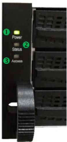
Figure 2.3.2.1
• LED lights description:
| 1 | Power LED:• Green → Power on.• Off → Power off. |
| 2 | Status LED:• Red → System is failure.• Off → System is good. |
| 3 | Access LED:• Blue → Host is accessing.• Off → Host is no access. |
2.3.3 Install drives
Note : Skip this section if you purchased a solution populated with drives.
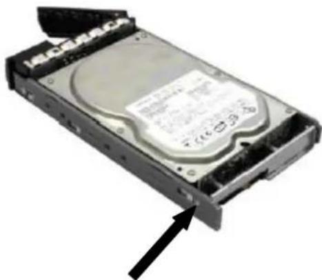
To install SAS or SATA drives with no Bridge Board use the front mounting holes:

natural_image
Close-up of a hard disk drive with visible internal components and mounting connectors (no text or symbols)To install SATA drives with Bridge Board (DSN-654), fit the Bridge Board first
natural_image
Close-up of a hard disk drive with an arrow pointing to its side panel (no visible text or symbols)Then install the drive using the rear mounting holes:

natural_image
Close-up of a hard disk drive with two black arrows pointing to its side (no visible text or symbols)
Figure 2.2.3.3
- HDD tray description:
| 1 | HDD power LED:• Green → HDD is inserted and good.• Off → No HDD. |
| 2 | HDD access LED:• Blue blinking → HDD is accessing.• Off → No HDD. |
| 3 | HDD tray handhold. |
| 4 | Latch for tray kit removal. |
2.3.4 Rear view
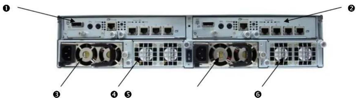
Figure 2.3.4.1 (DSN-6120)
• PSU and Fan module description:
| 1 | Controller 2. |
| 2 | Controller 1. |
| 3 | Power supply unit (PSU2). |
| 4 | Fan module (FAN3 / FAN4). |
| 5 | Power supply unit (PSU1). |
| 6 | Fan module (FAN1 / FAN2). |

Figure 2.3.4.2 (DSN-6110)
• PSU and Fan module description:
| 1 | Controller. |
| 2 | Power supply unit (PSU2). |
| 3 | Fan module (FAN3 / FAN4). |
| 4 | Power supply unit (PSU1). |
| 5 | Fan module (FAN1 / FAN2). |

Figure 2.3.4.3 (DSN-6110/6120)
- Connector, LED and button description:
| 1 | Gigabit ports (x4). |
| 2 | LED (from left to right)Controller Health LED:Green → Controller status normal or in the booting.Red → Other than above status.Master Slave LED: (only for DSN-6120)Green → Master controller.Off → Slave controller.Dirty Cache LED:Orange → Data on the cache waiting for flush to disks.Off → No data on the cache.BBM LED:Green → BBM installed and poweredOff → No BBM |
| 3 | BBM Status Button:When the system power is off, press the BBM status button, if the BBM LED is Green, then the BBM still has power to keep data on the cache. If not, then the BBM power is ran out and cannot keep the data on the cache anymore. |
| 4 | Management port. |
| 5 | Console port. |
| 6 | RS 232 port for UPS. |
| 7 | SAS JBOD expansion port. |
| 8 | Power switch. |
2.4 Install battery backup module
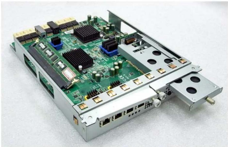
To install the IP SAN storage with a battery backup module, please follow the procedure.
- Shutdown IP SAN storage, then power off.
- Remove the cover of battery backup module.
- Insert the battery backup module.
natural_image
Green printed circuit board with various components and connectors, no visible text or symbolsFigure 2.4.1
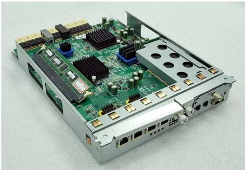
- Tighten the screws up.
- Power on, BBM will work.
natural_image
Electronic circuit board with various components and connectors, no visible text or symbolsFigure 2.4.2
2.5 Deployment
Please refer to the following topology and have all the connections ready.

flowchart
graph TD
    subgraph_DSN-6120_controller_1["DSN-6120 controller 1"]
        A["4"] --> B["3"] --> C["2"] --> D["1"]
        E["M"] --> F["Gigabit switch"]
        G["Console UPS"] --> H["BBM"]
        I["JBOD"] --> J["To DSN-6020"]
    end

    subgraph_DSN-6120_controller_2["DSN-6120 controller 2"]
        K["4"] --> L["3"] --> M["2"] --> N["1"]
        O["M"] --> P["Console UPS"] --> Q["JBOD"]
        R["BBM"] --> S["To DSN-6020"]
    end

    subgraph_Management_PC["Management PC"]
        T["RS 232"] --> U["NIC"]
        V["Switch"] --> W["APC Smart UPS (Optional) RS 232"]
        X["Gigabit switch"] --> Y["Gigabit switch"]
        Z["iSNS server (Recommended)"] --> AA["Gigabit switch"]
        AB["Host / Server"] --> AC["Gigabit switch"]
        AD["SAS cable"] --> AE["Red line"]
    end

    style DSN-6120_controller_1 fill:#f9f,stroke:#333
    style DSN-6120_controller_2 fill:#f9f,stroke:#333
Figure 2.5.1 (DSN-6120)
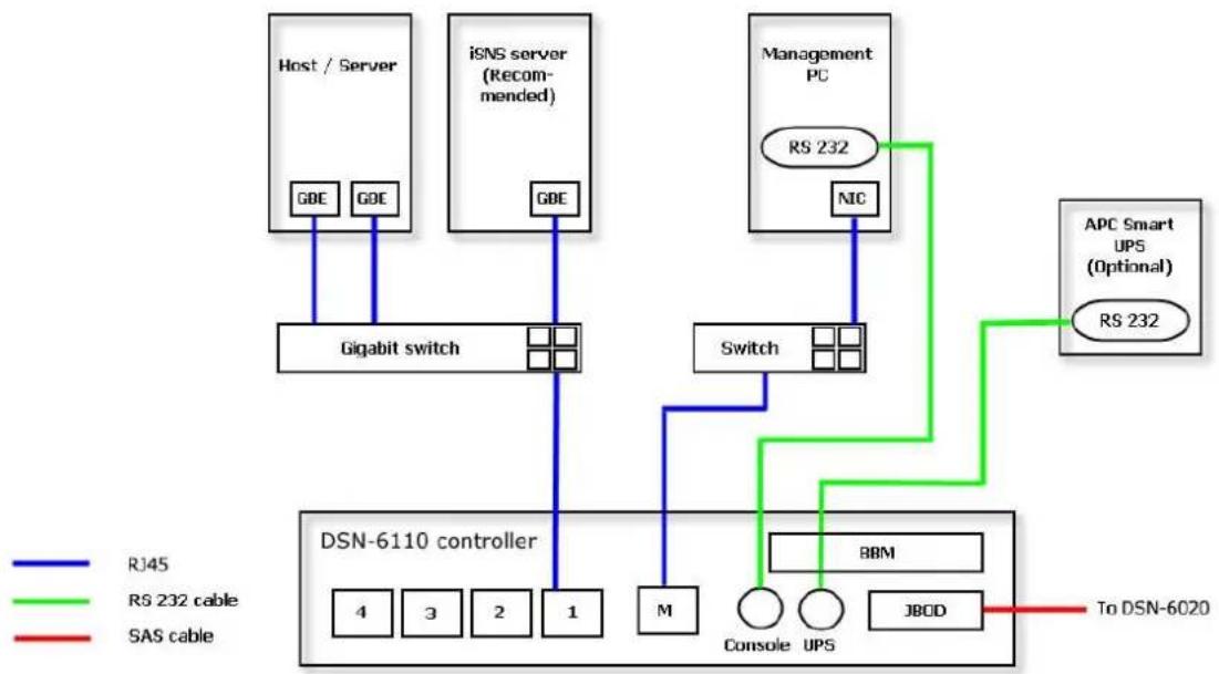
flowchart
graph TD
    A["Host / Server"] -->|GBE| B["Gigabit switch"]
    C["iSNS server (Recommended)"] -->|GBE| B
    D["Management PC"] -->|RS 232| E["NIC"]
    F["APC Smart UPS (Optional)"] -->|RS 232| E
    B --> G["DSN-6110 controller"]
    E --> G
    G --> H["4"]
    G --> I["3"]
    G --> J["2"]
    G --> K["1"]
    H --> L["M"]
    I --> M["Console UPS"]
    J --> N["JBCD"]
    K --> O["BBM"]
    style G fill:#f9f,stroke:#333
    style H fill:#ccf,stroke:#333
    style I fill:#ccf,stroke:#333
    style J fill:#ccf,stroke:#333
    style K fill:#ccf,stroke:#333
    style L fill:#cfc,stroke:#333
    style M fill:#cfc,stroke:#333
    style N fill:#cfc,stroke:#333
    style O fill:#fcc,stroke:#333
    style_P["To DSN-6020"] --> Q["Red arrow to right"]
Figure 2.5.2 (DSN-6110)
- Setup the hardware connection before power on servers. Connect console cable, management port cable, and iSCSI data port cables in advance.
- In addition, installing an iSNS server is recommended for dual controller system.
-
Power on DSN-6110/6120 and DSN-6020 (optional) first, and then power on hosts and iSNS server.
-
Host server is suggested to log on the target twice (both controller 1 and controller 2), and then MPIO should be setup automatically. (only for DSN-6120)

Tips
iSNS server is recommended for dual controller system.
For better data service availability, all the connections among host servers, GbE switches, and the dual controllers are recommended as redundant as below.

flowchart
graph TD
    A["Host / Server"] -->|GBE| B["Gigabit switch"]
    C["Host / Server"] -->|GBE| B
    D["Host / Server"] -->|GBE| E["Gigabit switch"]
    F["Host / Server"] -->|GBE| E
    B --> G["controller 1"]
    E --> H["controller 2"]
    G --> I["Controller 1"]
    H --> J["Controller 2"]
    style A fill:#f9f,stroke:#333
    style C fill:#f9f,stroke:#333
    style D fill:#f9f,stroke:#333
    style F fill:#f9f,stroke:#333
    style B fill:#ccf,stroke:#333
    style E fill:#ccf,stroke:#333
    style G fill:#cfc,stroke:#333
    style H fill:#cfc,stroke:#333
    style I fill:#fcc,stroke:#333
    style J fill:#fcc,stroke:#333
Figure 2.5.3 (only for DSN-6120)
Chapter 3 Quick setup
3.1 Management interfaces
There are three management methods to manage D-Link IP SAN storage, describe in the following:
3.1.1 Serial console
Use console cable (NULL modem cable) to connect from console port of D-Link IP SAN storage to RS 232 port of management PC. Please refer to figure 2.3.1. The console settings are on the following:
Baud rate: 115200, 8 data bit, no parity, 1 stop bit, and no flow control.
Terminal type: VT100
Login name: admin
Default password: 123456
3.1.2 Remote control
SSH (secure shell) software is required for remote login. The SSH client software is available at the following web site:
SSH Tectia Client: http://www.ssh.com/
PuTTY: http://www.chiark.greenend.org.uk/
Host name: 192.168.0.32 (Default IP)
Login name: admin
Default password: 123456

Tips
D-Link product supports SSH for remote control only. For using SSH, the IP address and password are required for login.
3.1.3 Web UI
D-Link IP SAN storage supports graphic user interface (GUI) to operate. Be sure to connect the LAN cable. The default IP setting is 192.168.0.32; open the browser and enter:
http://192.168.0.32
And then it will pop up a dialog for authentication.

Figure 3.1.4.1
User name: admin
Default password: 123456
After login, choose the functions which lists on the left side of window to make any configuration.
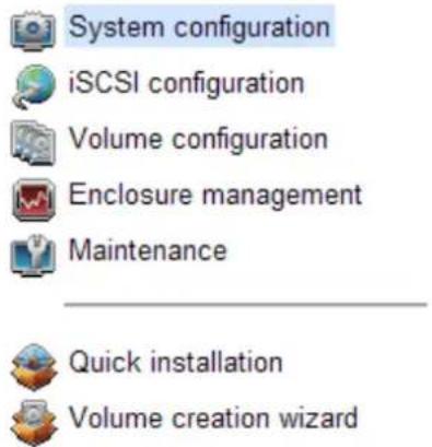
Figure 3.1.4.2
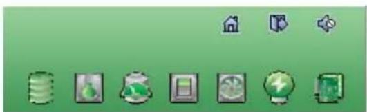
There are seven indicators and three icons at the top-right corner.
natural_image
Green background with eight small icons including books, gear, and a lightbulb (no text or symbols)Figure 3.1.4.3
- Indicator description:
| RAID light:Green → RAID works well.Red → RAID fails. | |
 | Temperature light:Green → Temperature is normal.Red → Temperature is abnormal. |
 | Voltage light:Green → voltage is normal.Red → voltage is abnormal. |
 | UPS light:Green → UPS works well.Red → UPS fails. |
 | Fan light:Green → Fan works well.Red → Fan fails. |
 | Power light:Green → Power works well.Red → Power fails. |
 | Dual controller light:Green → Both controller 1 and controller 2 are present and well.Orange → The system is degraded and there is only 1 controller alive and well. |
 | Return to home page. |
 | Logout the management web UI. |
 | Mute alarm beeper. |

Tips
If the status indicators in Internet Explorer (IE) are displayed not in blinking red, please enable "Internet Options" → "Advanced" → "Play animations in webpages" options in IE. The default value is enabled, but some applications will disable it.
in
3.2 How to use the system quickly
The following methods will describe the quick guide to use this IP SAN storage.
3.2.1 Quick installation
Please make sure that there are some free drives installed in this system. SAS drives are recommended. Please check the hard drive details in "/ Volume configuration / Physical disk".
| Physical disk | RAID group | Virtual disk | Snapshot | Logical unit | Replication | ||||||||
| Show PD for: - Local - Show size unit as: (GB) | |||||||||||||
| Slot | Size(GB) | RG | Status | Health | Usage | Vendor | Serial | Type | Write cache | Standby | Roadahead | Command quouing | |
| OP | 1 | 68 | 0 | Online | Good | RAID disk | SEAGATE | 3LQ41E1T | SAS | Enabled | Disabled | Enabled | Enabled |
| OP | 2 | 68 | 0 | Online | Good | RAID disk | SEAGATE | 3LQ0TLPF | SAS | Enabled | Disabled | Enabled | Enabled |
| OP | 3 | 68 | 0 | Online | Good | RAID disk | SEAGATE | 3LQ1GX3E | SAS | Enabled | Disabled | Enabled | Enabled |
| OP | 4 | 68 | 0 | Online | Good | RAID disk | SEAGATE | 3LQ0TMVJ | SAS | Enabled | Disabled | Enabled | Enabled |
| OP | 5 | 33 | 0 | Online | Good | RAID disk | SEAGATE | 3KQ1VEV8 | SAS | Enabled | Disabled | Enabled | Enabled |
| OP | 6 | 33 | 0 | Online | Good | RAID disk | SEAGATE | 3KQ1VMEZ | SAS | Enabled | Disabled | Enabled | Enabled |
| OP | 7 | 136 | 0 | Online | Good | RAID disk | SEAGATE | 3LN6TS1D | SAS | Enabled | Disabled | Enabled | Enabled |
| OP | 8 | 136 | 0 | Online | Good | RAID disk | SEAGATE | 3LN4X8HV | SAS | Enabled | Disabled | Enabled | Enabled |
| OP | 9 | 465 | 0 | Online | Good | RAID disk | SEAGATE | 9QMBKDZL000099445E9C | SAS | Enabled | Disabled | Enabled | Enabled |
| OP | 10 | 465 | 0 | Online | Good | RAID disk | Seagate | 3PMOHNQT | SATA2 | Enabled | Disabled | Enabled | Enabled |
| OP | 11 | 931 | 0 | Online | Good | RAID disk | Seagate | 9QJ1HT1P.0 9QJ1HT1P.0 9QJ1HT1P.0 9QJ1HT1P.0 9QJ1HT1P.0 9QJ1HT1P.0 9QJ1HT1P.0 9QJ1HT1P.0 9QJ1HT1P.0 9QJ1HT1P.0 9QJ1HT1P.0 9QJ1HT1P.0 9QJ1HT1P.0 9QJ1HT1P.0 9QJ1HT1P.0 9QJ1HT1P.0 9QJ1HT1P.0 9QJ1HT1P.0 9QJ1HT1P.0 9QJ1HT1P.0 9QJ1HT1P.0 | |||||
Figure 3.2.1.1
Step1: Click the "Quick installation" menu item; follow the steps to set up system name and date / time.

Figure 3.2.1.2
Step2: Confirm the management port IP address and DNS, and then click "Next".

Figure 3.2.1.3
Step 3: Set up the data port IP and click "Next".
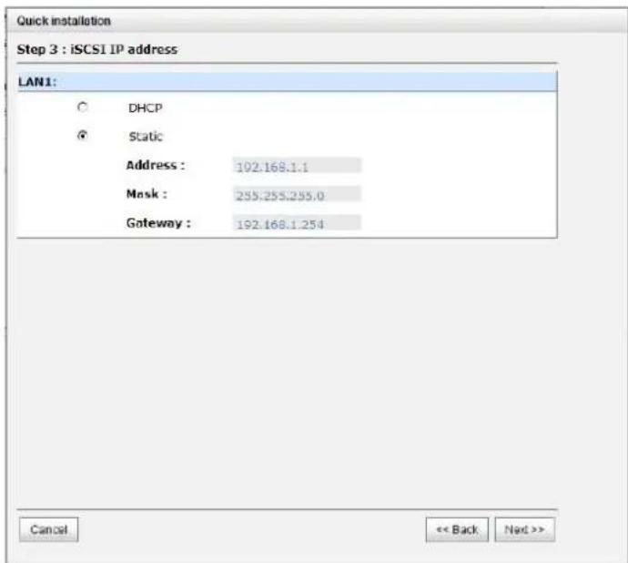
Figure 3.2.1.4
Step 4: Set up the RAID level and volume size and click "Next".
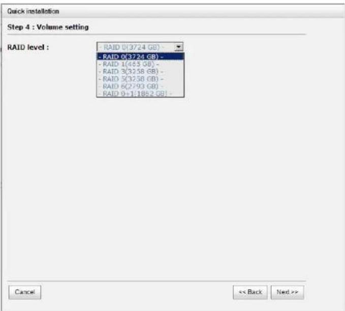
Figure 3.2.1.5
Step 5: Check all items, and click "Finish".
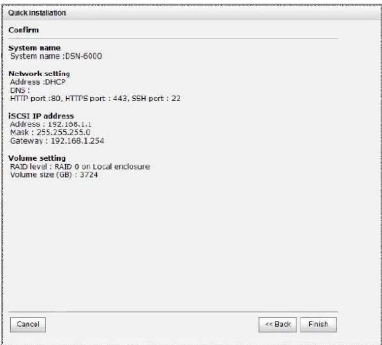
Figure 3.2.1.6
3.2.2 Volume creation wizard
"Volume create wizard" has a smarter policy. When the system is inserted with some HDDs. "Volume create wizard" lists all possibilities and sizes in different RAID levels, it will use all available HDDs for RAID level depends on which user chooses. When system has
different sizes of HDDs, e.g., 8*200G and 8*80G, it lists all possibilities and combination in different RAID level and different sizes. After user chooses RAID level, user may find that some HDDs are available (free status). The result is using smarter policy designed by D-Link. It gives user:
- Biggest capacity of RAID level for user to choose and,
- The fewest disk number for RAID level / volume size.
E.g., user chooses RAID 5 and the controller has 12^200G + 4^80G HDDs inserted. If we use all 16 HDDs for a RAID 5, and then the maximum size of volume is 1200G ( 80G^15 ). By the wizard, we do smarter check and find out the most efficient way of using HDDs. The wizard only uses 200G HDDs (Volume size is 200G^11 = 2200G ), the volume size is bigger and fully uses HDD capacity.
Step 1: Select "Volume create wizard" and then choose the RAID level. After the RAID level is chosen, click "Next".

Figure 3.2.2.1
Step 2: Please select the combination of the RG capacity, or "Use default algorithm" for maximum RG capacity. After RG size is chosen, click "Next".

Figure 3.2.2.2
Step 3: Decide VD size. User can enter a number less or equal to the default number. Then click "Next".
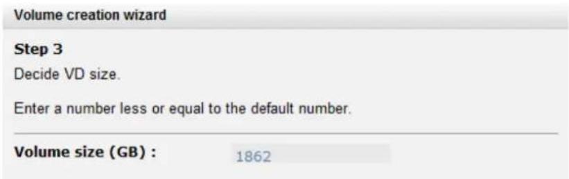
Figure 3.2.2.3
Step 4: Confirmation page. Click "Finish" if all setups are correct. Then a VD will be created.
Step 5: Done. The system is available now.
| Name | Size(GB) | Write | Priority | By rate | Type | Clone | Schedule | Status | Health | R % | RAID | #LUN | Snapshot space(GB) | #Snapshot | RG | |
| OP | QUICK71147 | 1862 | WB | HI | 4 | RAID | N/A | N/A | Online | Optimal | RAID 0 | 1 | 0/0 | 0 | QUICK42321 |
Figure 3.2.2.4
(Figure 3.2.2.4: A virtual disk of RAID 0 is created and is named by system itself.)
Chapter 4 Configuration
4.1 Web UI management interface hierarchy
The below table is the hierarchy of web GUI.
System configuration
| System setting → | System name / Date and time / System indication |
| Network setting → | MAC address / Address / DNS / Port |
| Login setting → | Login configuration / Admin password / User password |
| Mail setting → | |
| Notification → | SNMP / Messenger / System log server / Event log filter |
| setting |
iSCSI configuration
| NIC → | Show information for:(Controller 1/ Controller 2)Aggregation / VLAN / IP settings for iSCSI ports / Become default gateway / Enable jumbo frame / Ping host |
| perty → | Entity name / iSNS IP |
| Node → | Show information for:(Controller 1/ Controller 2)Authenticate / Change portal / Rename alias/ User |
| ssion → | Show information for:(Controller 1/ Controller 2)List connection / Delete |
| ount → | Create / Modify user information / Delete |
Volume configuration
| Physical disk → | Set Free disk / Set Global spare / Set Dedicated spare / Upgrade / Disk Scrub / Turn on/off the indication LED / More information |
| RAID group → | Create / Migrate / Activate / Deactivate / Parity check / Delete / Set preferred owner / Set disk property / More information |
| Virtual disk → | Create / Extend / Parity check / Delete / Set property / Attach LUN / Detach LUN / List LUN / Set clone / Clear clone / Start clone / Stop clone / Schedule clone / Set snapshot space / Cleanup snapshot / Take snapshot / Auto snapshot / List snapshot / More information |
| Snapshot → | Set snapshot space / Auto snapshot / Take snapshot / Export / Rollback / Delete/ Cleanup snapshot |
| Logical unit → | Attach / Detach/ Session |
Enclosure management
| Hardware monitor | → | Controller 1 / BPL / Controller 2 / Auto shutdown |
| UPS | → UPS Type / Shutdown battery level / Shutdown delay / Shutdown UPS | |
| SES | → Enable / Disable | |
| S.M.A.R.T. | → | S.M.A.R.T. information (Only for SATA hard drives) |
Maintenance
System → System information
information
Event log → Download / Mute / Clear

flowchart
graph TD
    A["Upgrade"] --> B["Browse the firmware to upgrade"]
    C["Firmware synchronization"] --> D["Synchronize the slave controller's firmware version with the master's"]
    E["Reset to factory default"] --> F["Sure to reset to factory default?"]
    G["Import and export"] --> H["Import/Export / Import file"]
    I["Reboot and shutdown"] --> J["Reboot / Shutdown"]
    K["Quick installation"] --> L["Step 1 / Step 2 / Step 3 / Step 4 / Confirm"]
    M["Volume creation wizard"] --> N["Step 1 / Step 2 / Step 3 / Confirm"]
4.2 System configuration
“System configuration” is designed for setting up the “System setting”, “Network setting”, “Login setting”, “Mail setting”, and “Notification setting”.
| System setting | Network setting | Login setting | Mail setting | Notification setting |
Figure 4.2.1
4.2.1 System setting
“System setting” can setup system name and date. Default “System name” is composed of model name and serial number of this system.
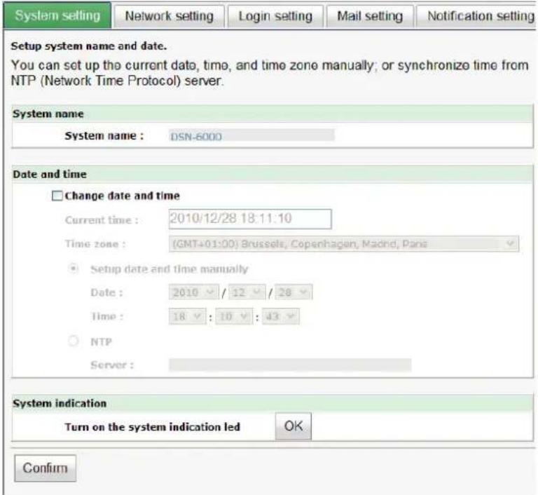
Figure 4.2.1.1
Check “Change date and time” to set up the current date, time, and time zone before using or synchronize time from NTP (Network Time Protocol) server. Click “Confirm” in System indication to turn on the system indication LED. Click again to turn off.
4.2.2 Network setting
"Network setting" is for changing IP address for remote administration usage. are 2 options, DHCP (Get IP address from DHCP server) and static IP. The default setting is DHCP. User can change the HTTP, HTTPS, and SSH port number when the default port number is not allowed on host/server.
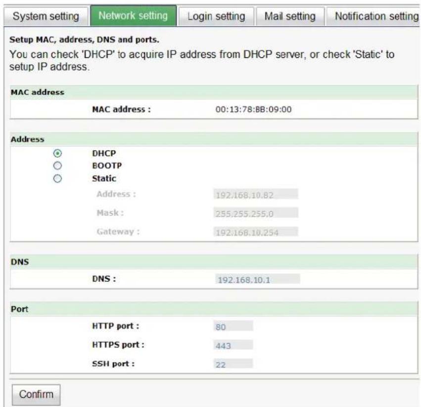
Figure 4.2.2.1
4.2.3 Login setting
"Login setting" can set single admin, auto logout time and admin / user password. The single admin is to prevent multiple users access the same system in the same time.
- Auto logout: The options are (1) Disabled; (2) 5 minutes; (3) 30 minutes; (4) 1 hour. The system will log out automatically when user is inactive for a period of time.
- Login lock: Disabled or Enabled. When the login lock is enabled, the system allows only one user to login or modify system settings.

Figure 4.2.3.1
Check "Change admin password" or "Change user password" to change admin or user password. The maximum length of password is 12 characters.
4.2.4 Mail setting
"Mail setting" can enter 3 mail addresses for receiving the event notification. Some mail servers would check "Mail-from address" and need authentication for anti-spam. Please fill the necessary fields and click "Send test mail" to test whether email functions are available. User can also select which levels of event logs are needed to be sent via Mail. Default setting only enables ERROR and WARNING event logs. Please also make sure the DNS server IP is well-setup so the event notification mails can be sent successfully.

Figure 4.2.4.1
4.2.5 Notification setting
"Notification setting" can set up SNMP trap for alerting via SNMP, pop-up message via Windows messenger (not MSN), alert via syslog protocol, and event log filter for web UI.
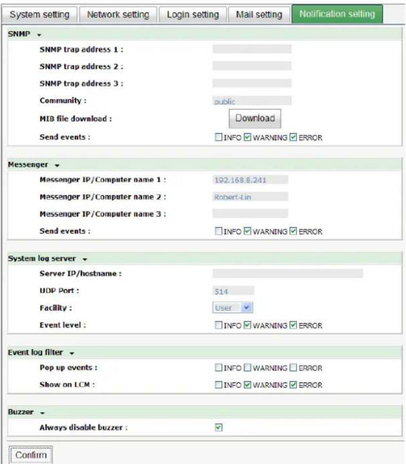
Figure 4.2.5.1
"SNMP" allows up to 3 SNMP trap addresses. Default community setting is "public". User can choose the event log levels and default setting enables ERROR and WARNING event log in SNMP. There are many SNMP tools. The following web sites are for your reference:
SNMPc: http://www.snmpc.com/
Net-SNMP: http://net-snmp.sourceforge.net/
If necessary, click "Download" to get MIB file and import to SNMP.
To use “Messenger”, user must enable the service “Messenger” in Windows (Start → Control Panel → Administrative Tools → Services → Messenger), and then event logs can be received. It allows up to 3 messenger addresses. User can choose the event log levels and default setting enables the WARNING and ERROR event logs.
Using "System log server", user can choose the facility and the event log level. The default port of syslog is 514. The default setting enables event level: INFO, WARNING and ERROR event logs.
There are some syslog server tools. The following web sites are for your reference:
WinSyslog: http://www.winsyslog.com/
Kiwi Syslog Daemon: http://www.kiwisyslog.com/
Most UNIX systems build in syslog daemon.
"Event log filter" setting can enable event log display on "Pop up events".
4.3 iSCSI configuration
“iSCSI configuration” is designed for setting up the “Entity Property”, “NIC”, “Node”, “Session”, and “CHAP account”.

Figure 4.3.1
4.3.1 NIC
“NIC” can change IP addresses of iSCSI data ports. DSN-6110/6120 has four gigabit ports on each controller to transmit data. Each of them must be assigned to an IP address and be set up in multi-homed mode, or the link aggregation / trunking mode has been set up. When there are multiple data ports setting up in link aggregation or trunking mode, all the data ports share single address.
| Show information for: Controller 2 | |||||||||||
| Name | LAG | LAG No | VLAN ID | DHCP | IP address | Netmask | Gateway | Jumbo frame | MAC address | Link | |
| OP. | LAN1 | No | N/A | N/A | No | 192.168.11.5 | 255.255.255.0 | Disabled | 00:13:78:bb:09:0c | Up | |
| OP. | LAN2 | No | N/A | N/A | No | 192.168.12.6 | 255.255.255.0 | Disabled | 00:13:78:bb:09:0d | Up | |
| OP. | LAN3 | No | N/A | N/A | No | 192.168.11.7 | 255.255.255.0 | Disabled | 00:13:78:bb:09:0e | Up | |
| OP. | LAN4 | No | N/A | N/A | No | 192.168.12.8 | 255.255.255.0 | Disabled | 00:13:78:bb:09:0f | Up | |
Figure 4.3.1.1
(Figure 4.3.1.1: There are 4 iSCSI data ports on each controller. 4 data ports are set with static IP.)
- IP settings:
User can change IP address by checking the gray button of LAN port, click "IP settings for iSCSI ports". There are 2 selections, DHCP (Get IP address from DHCP server) or static IP.

Figure 4.3.1.2
- Default gateway:
Default gateway can be changed by checking the gray button of LAN port, click "Become default gateway". There can be only one default gateway.
- MTU / Jumbo frame:
MTU (Maximum Transmission Unit) size can be enabled by checking the gray button of LAN port, click "Enable jumbo frame". Maximum jumbo frame size is 3900 bytes.

Caution
The MTU size of switching hub and HBA on host must be enabled. Otherwise, the LAN connection can not work properly.
• Multi-homed / Trunking / LACP:
The following is the description of multi-homed / trunking / LACP functions.
- Multi-homed: Default mode. Each of iSCSI data port is connected by itself and is not link aggregation and trunking. This function is also for Multipath functions. Select this mode can also remove the setting of Trunking / LACP in same time.
- Trunking: defines the use of multiple iSCSI data ports in parallel to increase the link speed beyond the limits of any single port.
- LACP: The Link Aggregation Control Protocol (LACP) is part of IEEE specification 802.3ad that allows bundling several physical ports together to form a single logical channel. LACP allows a network switch to negotiate an automatic bundle by sending
LACP packets to the peer. The advantages of LACP are (1) increases the bandwidth. (2) failover when link status fails on a port.
Trunking / LACP setting can be changed by clicking the button "Aggregation".

Figure 4.3.1.3
(Figure 4.3.1.3: There are 4 iSCSI data ports on each controller, select at least two NICs for link aggregation.)
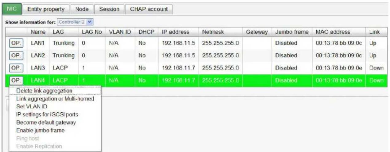
Figure 4.3.1.4
For example, LAN1 and LAN2 are set as Trunking mode. LAN3 and LAN4 are set as LACP mode. To remove Trunking / LACP setting, check the gray button of LAN port, click "Delete link aggregation". Then it will pop up a message to confirm.
- Ping host:
User can ping the corresponding host data port from the target, click "Ping host".
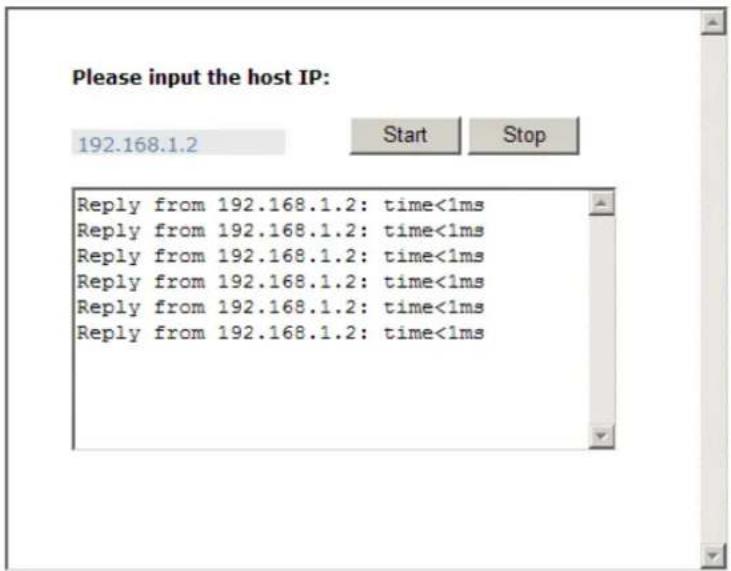
Figure 4.3.1.5
(Figure 4.3.1.5 shows a user can ping host from the target to make sure the data port connection is well.)
4.3.2 Entity property
"Entity property" can view the entity name of the system, and setup "iSNS IP" for iSNS (Internet Storage Name Service). iSNS protocol allows automated discovery, management and configuration of iSCSI devices on a TCP/IP network. Using iSNS, it needs to install an iSNS server in SAN. Add an iSNS server IP address into iSNS server lists in order that iSCSI initiator service can send queries. The entity name can be changed.
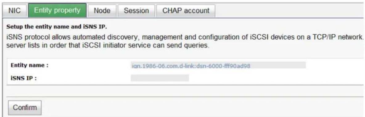
Figure 4.3.2.1
4.3.3 Node
"Node" can view the target name for iSCSI initiator. DSN-6110/6120 supports up to 32 multi-nodes. There are 32 default nodes created for each controller.
| Show information for: | |||||
| << first < prev 1 2 3 next > last >> | |||||
| ID | Auth | Name | Portal | Alias | |
| OP. | 0 | None | iqn.1986-06.com.d-link:dsn-6000-fff90ad98:dev0.ctr1 | 192.168.1.1:3260, 192.168.2.1:3260, 0.0.0.0:3260, 192.168.4.1:3260 | |
| OP. | 1 | None | iqn.1986-06.com.d-link:dsn-6000-fff90ad98:dev1.ctr1 | 192.168.1.1:3260, 192.168.2.1:3260, 0.0.0.0:3260, 192.168.4.1:3260 | |
| OP. | 2 | None | iqn.1986-06.com.d-link:dsn-6000-fff90ad98:dev2.ctr1 | 192.168.1.1:3260, 192.168.2.1:3260, 0.0.0.0:3260, 192.168.4.1:3260 | |
| OP. | 3 | None | iqn.1986-06.com.d-link:dsn-6000-fff90ad98:dev3.ctr1 | 192.168.1.1:3260, 192.168.2.1:3260, 0.0.0.0:3260, 192.168.4.1:3260 | |
| OP. | 4 | None | iqn.1986-06.com.d-link:dsn-6000-fff90ad98:dev4.ctr1 | 192.168.1.1:3260, 192.168.2.1:3260, 0.0.0.0:3260, 192.168.4.1:3260 | |
| OP. | 5 | None | iqn.1986-06.com.d-link:dsn-6000-fff90ad98:dev5.ctr1 | 192.168.1.1:3260, 192.168.2.1:3260, 0.0.0.0:3260, 192.168.4.1:3260 | |
| OP. | 6 | None | iqn.1986-06.com.d-link:dsn-6000-fff90ad98:dev6.Ctr1 | 192.168.1.1:3260, 192.168.2 1:3260, 0.0.0.0:3260, 192.168.4.1:3260 | |
| OP | 7 | None | iqn. 1986-06.com.d-link:dsn-6000-fff90ad98:dev7 ctr1 | 192.168.1.1:3260, 192.168.2 1:3260, 0.0.0.0:3260, 192.168.4.1:3260 | |
| OP | 8 | None | iqn 1986-06.com.d-link:dsn-6000-fff90ad98:dev8 ctr1 | 192 168 1 . 1 : 3260 , 192 168 2 . 1 : 3260 , 0 . 0 . 0 . 3260 , 192 . 168 . 4 . 1 : 3260 | |
| OP | 9 | None | iqn 1986-06 com.d-link dsn-6000-fff90ad98 dev9 ctr1 | 192 . 168 . 1 . 1 : 3260 , 192 . 168 . 2 . 1 : 3260 , 0 . 0 . 0 . 3260 , 192 . 168 .4 . 1 : 3260 | |
| OP | 10 | None | iqn 1986-06 com.d-link dsn-600o- fff9oad98:dev1o.ctrl | 192 . 168 . 1 . 1 : 3260 , 192 . 168 . 2 . 1 : 3260 , 0 . 0 . 0 . 3260 , 192 . 168 .4 . 1 : 3260 | |
| OP | 11 | None | iqn 1986-06 com.d-link dsn-600o- fff9oad98:dev1l.ctrl | 192 . 168 . 1 . 1 : 3260 , 192 . 168 . 2 . 1 : 3260 , 0 . 0 . 0 . 3260 , 192 . 168 .4 . 1 : 3260 | |
Figure 4.3.3.1
- CHAP:
CHAP is the abbreviation of Challenge Handshake Authentication Protocol. CHAP is a strong authentication method used in point-to-point for user login. It's a type of authentication in which the authentication server sends the client a key to be used for encrypting the username and password. CHAP enables the username and password to transmit in an encrypted form for protection.
To use CHAP authentication, please follow the procedures.
- Select one of 32 default nodes from one controller.
- Check the gray button of "OP." column, click "Authenticate".
- Select "CHAP".

Figure 4.3.3.2
- Click "OK".
| ID | Auth | Name | Portal | Alias | |
| OP. | 0 | CHAP | iqn.1986-06.com.d-link:dsn-6000-fff90ad98:dev0.ctr1 | 192.168.1 1:3260, 192.168.2.1:3260, 0.0.0.0:3260, 192.168.4.1:3260 | |
| OP. | 1 | CHAP | iqn.1986-06.com.d-link:dsn-6000-fff90ad98:dev1.ctr1 | 192.168.1.1.3260, 192.168.2.1.3260, 0.0.0.0:3260, 192.168.4.1:3260 | |
| OP. | 2 | None | iqn.1986-06.com.d-link:dsn-6000-fff90ad98:dev2.ctr1 | 192.168.1.1:3260, 192.168.2.1:3260, 0.0.0.0:3260, 192.168.4.1:3260 | |
| OP. | 3 | None | iqn.1986-06.com.d-link:dsn-6000-fff90ad98:dev3.ctr1 | 192.168.1 1:3260, 192.168.2.1:3260, 0.0.0.0:3260, 192.168.4.1:3260 |
Figure 4.3.3.3
- Go to "/ iSCSI configuration / CHAP account" page to create CHAP account. Please refer to next section for more detail.
- Check the gray button of "OP." column, click "User".
- Select CHAP user(s) which will be used. It's a multi option; it can be one or more. If choosing none, CHAP can not work.
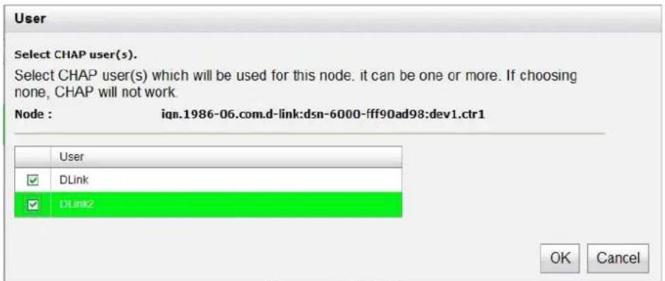
Figure 4.3.3.4
- Click "OK".
- In "Authenticate" of "OP" page, select "None" to disable CHAP.
- Change portal:
Users can change the portals belonging to the device node of each controller.
- Check the gray button of "OP." column next to one device node.
- Select "Change portal".
- Choose the portals for the controller.
- Click "OK" to confirm.

Figure 4.3.3.5
- Rename alias:
User can create an alias to one device node.
- Check the gray button of "OP." column next to one device node.
- Select "Rename alias".
- Create an alias for that device node.
- Click "OK" to confirm.
- An alias appears at the end of that device node.
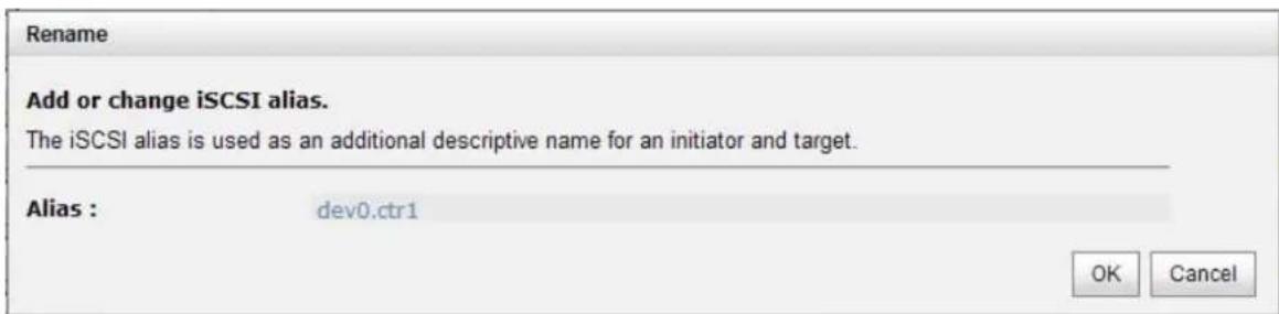
Figure 4.3.3.6
| ID | Auth | Name | Portal | Alias | |
| OP. | 0 | CHAP | ign 1986-06.com.d-link:dsn-6000- fff90ad98.dev0.ctr1 | 192.168.1.1:3260, 192.168.2.1:3260, 192.168.1.1:3260, 192.168.4.1.3260 | dev0. ctr1 |
| OP. | 1 | CHAP | ign 1986-06.com.d-link:dsn-6000- fff90ad98.dev1.ctr1 | 192.168.1.1:3260, 192.168.2.1:3260, 192.168.1.1:3260, 192.168.4.1.3260 | |
| OP. | 2 | None | ign 1986-06.com.d-link:dsn-6000- fff90ad98:dev2. ctr1 | 192.168.1.1:3260, 192.168.2.1:3260, 192.168.1.1:3260, 192.168.4.1.3260 | |
| OP | 3 | None | ign 1986-06.com.d-link:dsn-6000- fff90ad98:dev3. ctr1 | 192.168.1.1:3260, 192.168.2.1:3260, 192.168.1.1:3260, 192.168.4.1:3260 |
Figure 4.3.3.7

Tips
After setting CHAP, the initiator in host should be set with the same CHAP account. Otherwise, user cannot login.
4.3.4 Session
"Session" can display current iSCSI session and connection information, including the following items:
- TSIH (target session identifying handle)
- Host (Initiator Name)
- Controller (Target Name)
- InitialR2T(Initial Ready to Transfer)
- Immed. data(Immediate data)
- MaxDataOutR2T(Maximum Data Outstanding Ready to Transfer)
- MaxDataBurstLen(Maximum Data Burst Length)
- DataBeginOrder(Data Sequence in Order)
- DataPDUInOrder(Data PDU in Order)
- Detail of Authentication status and Source IP: port number.

Figure 4.3.4.1 (iSCSI Session)
Check the gray button of session number, click "List connection". It can list all connection(s) of the session.

Figure 4.3.4.2 (iSCSI Connection)
4.3.5 CHAP account
"CHAP account" can manage a CHAP account for authentication. DSN-6110/6120 can create multiple CHAP accounts.
To setup CHAP account, please follow the procedures.
- Click "Create".
- Enter "User", "Secret", and "Confirm" secret again. "Node" can be selected here or later. If selecting none, it can be enabled later in "/iSCSI configuration / Node / User".

Figure 4.3.5.1
3. Click "OK".

Figure 4.3.5.2
4. Click "Delete" to delete CHAP account.
4.4 Volume configuration
"Volume configuration" is designed for setting up the volume configuration which includes "Physical disk", "RAID group", "Virtual disk", "Snapshot", "Logical unit", and "Replication" (optional).
| Physical disk | RAID group | Virtual disk | Snapshot | Logical unit | Replication |
Figure 4.4.1
4.4.1 Physical disk
"Physical disk" can view the status of hard drives in the system. The followings are operational steps:
- Check the gray button next to the number of slot, it will show the functions which can be executed.
- Active function can be selected, and inactive functions show up in gray color and cannot be selected.
For example, set PD slot number 4 to dedicated spare disk.
Step 1: Check to the gray button of PD 4, select "Set Dedicated spare", it will link to next page.
| Slot | Size(GB) | RG | Status | Health | Usage | Vendor | Serial | Type | Write cache | Standby | Readahead | Command queuing | |
| OP | 1 | 465 | RG-R5 | Online | Good | RAID disk | SEAGATE | 3QM00X1W00009843LV6Z | SAS | Enabled | Disabled | Enabled | Enabled |
| OP | 2 | 466 | RG-R5 | Online | Good | RAID disk | SEAGATE | 9QMBKDSX000099445E69 | SAS | Enabled | Disabled | Enabled | Enabled |
| OP | 3 | 466 | RG-R5 | Online | Good | RAID disk | SEAGATE | 9QMBKV6R00009942TKPJ | SAS | Enabled | Disabled | Enabled | Enabled |
| OP | 4 | 466 | Online | Good | Free disk | SEAGATE | 9QMBKEZW000099445C09 | SAS | Enabled | Disabled | Enabled | Enabled | |
| Set Free disk | Online | Good | Free disk | SEAGATE | 9QMBKE81000099445DVM | SAS | Enabled | Disabled | Enabled | Enabled | |||
| Set Global spare | |||||||||||||
| Set Dedicated spare | Online | Good | Free disk | SEAGATE | 9QM4FLD00009845WFC9 | SAS | Enabled | Disabled | Enabled | Enabled | |||
| Upgrade Disk Scrub | |||||||||||||
Figure 4.4.1.1
Step 2: If there is any RG which is in protected RAID level and can be set with dedicate spare disk, select one RG, and then click "Submit".

Figure 4.4.1.2
Step 3: Done. View "Physical disk" page.
| Show PD for: - Local Show size unit as: (GB) | |||||||||||||
| Slot | Size(GB) | RG | Status | Health | Usage | Vendor | Serial | Type | Write cache | Standby | Readahead | Command queuing | |
| OP | 1 | 465 | RG-R5 | Online | Good | RAID disk | SEAGATE | 3QM00X1W00009843LV5Z | SAS | Enabled | Disabled | Enabled | Enabled |
| OP | 2 | 465 | RG-R5 | Online | Good | RAID disk | SEAGATE | 9QMBKDSX000099445E69 | SAS | Enabled | Disabled | Enabled | Enabled |
| OP | 3 | 465 | RG-R5 | Online | Good | RAID disk | SEAGATE | 9QMBKV8R00009942TKPJ | SAS | Enabled | Disabled | Enabled | Enabled |
| OP | 4 | 465 | RG-R5 | Online | Good | Dedicated spare | SEAGATE | 9QMBKE2W000099445C09 | SAS | Enabled | Disabled | Enabled | Enabled |
| OP | 5 | 465 | Online | Good | Free disk | SEAGATE | 9QMBKE81000099445DVM | SAS | Enabled | Disabled | Enabled | Enabled | |
| OP | 6 | 465 | Online | Good | Free disk | SEAGATE | 9QM4AFLD00001845WFC9 | SAS | Enabled | Disabled | Enabled | Enabled | |
| OP | 7 | 465 | Online | Good | Free disk | SEAGATE | 9QMBVLL90000900JYYHD | SAS | Enabled | Disabled | Enabled | Enabled | |
| OP | 8 | 465 | Online | Good | Free disk | SEAGATE | 9QMBKDVP000099445B7N | SAS | Enabled | Disabled | Enabled | Enabled | |
Figure 4.4.1.3
(Figure 4.4.1.3: Physical disks in slot 1,2,3 are created for a RG named "RG-R5". Slot 4 is set as dedicated spare disk of the RG named "RG-R5". The others are free disks.)
Step 4: The unit of size can be changed from (GB) to (MB). It will display the capacity of hard drive in MB.
| Show PD for: - Local - Show size unit as: (MB) (GB) (MB) | ||||||
| Slot | Size(MB) | RG | Status | Health | Usage | |
| OP | 1 | 476684 | RG-R5 | Online | Good | RAID disk |
| OP | 2 | 476684 | RG-R5 | Online | Good | RAID disk |
| OP | 3 | 476684 | RG-R5 | Online | Good | RAID disk |
| OP | 4 | 476684 | RG-R5 | Online | Good | Dedicated spare |
| OP | 5 | 476684 | Online | Good | Free disk | |
| OP | 6 | 476684 | Online | Good | Free disk | |
| OP | 7 | 476684 | Online | Good | Free disk | |
| OP | 8 | 476684 | Online | Good | Free disk | |
Figure 4.4.1.4
- PD column description:
| Slot | The position of a hard drive. The button next to the number of slot shows the functions which can be executed. |
| Size (GB) (MB) | Capacity of hard drive. The unit can be displayed in GB or MB. |
| RG Name RAID group name. | |
| Status The status of hard drive:“Online” → the hard drive is online.“Rebuilding” → the hard drive is being rebuilt.“Transition” → the hard drive is being migrated or is replaced by another disk when rebuilding occurs.“Scrubbing” → the hard drive is being scrubbed. | |
| Health The health of hard drive:“Good” → the hard drive is good.“Failed” → the hard drive is failed.“Error Alert” → S.M.A.R.T. error alert.“Read Errors” → the hard drive has unrecoverable read errors. | |
| Usage The usage of hard drive:“RAID disk” → This hard drive has been set to a | |
| RAID group. “Free disk” → This hard drive is free for use. “Dedicated spare” → This hard drive has been set as dedicated spare of a RG. “Global spare” → This hard drive has been set as global spare of all RGs. | |
| Vendor Hard drive vendor. | |
| Serial Hard drive serial number. | |
| Type Hard drive type: “SATA” → SATA disk. “SATA2” → SATA II disk. “SAS” → SAS disk. | |
| Write cache | Hard drive write cache is enabled or disabled. Default is “Enabled”. |
| Standby | HDD auto spindown to save power. Default is “Disabled”. |
| Readahead | This feature makes data be loaded to disk's buffer in advance for further use. Default is “Enabled”. |
| Command queuing | Newer SATA and most SCSI disks can queue multiple commands and handle one by one. Default is “Enabled”. |
• PD operation description:
| Set Free disk | Make the selected hard drive be free for use. |
| Set Global spare | Set the selected hard drive to global spare of all RGs. |
| Set Dedicated spares | Set a hard drive to dedicated spare of the selected RG. |
| Upgrade Upgrade | grade hard drive firmware. |
| Disk Scrub Scrub | the hard drive. |
| Turn on/ offthe indication LED | Turn on the indication LED of the hard drive. Click again to turnoff. |
| More information | Show hard drive detail information. |
4.4.2 RAID group
"RAID group" can view the status of each RAID group, create, and modify RAID groups. The following is an example to create a RG.
Step 1: Click "Create", enter "Name", choose "RAID level", click "Select PD" to select PD, assign the RG's "Preferred owner". Then click "OK". The "Write Cache" option is to enable or disable the write cache option of hard drives. The "Standby" option is to enable or disable the auto spindown function of hard drives, when this option is enabled and hard drives have no I/O access after certain period of time, they will spin down automatically. The "Readahead" option is to enable or disable the read ahead function. The "Command queuing" option is to enable or disable the hard drives' command queue function.
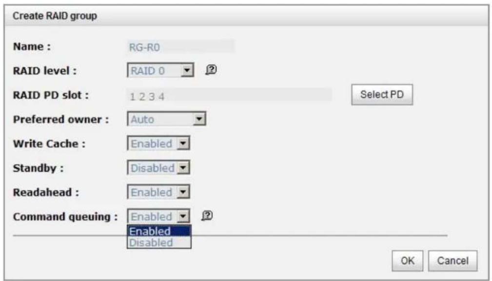
Figure 4.4.2.1
Step 2: Confirm page. Click "OK" if all setups are correct.
| Show size unit as: (GB) ▼ | ||||||||||
| Name | Total(GB) | Free(GB) | #PD | #VD | Status | Health | RAID | Current owner | Preferred owner | |
| OP. | RG-R0 | 1862 | 1862 | 4 | 0 | Online | Good | RAID 0 | Controller 1 | Controller 1 |
| OP. | RG-R5 | 931 | 931 | 3 | 0 | Online | Good | RAID 5 | Controller 1 | Controller 1 |
| Migrate Activate Deactivate Parity check Delete Set preferred owner Set disk property More information | ||||||||||
Figure 4.4.2.2
(Figure 4.4.2.2: There is a RAID 0 with 4 physical disks, named "RG-R0". The second RAID group is a RAID 5 with 3 physical disks, named "RG-R5".)
Step 3: Done. View "RAID group" page.
• RG column description:
| The button includes the functions which can be executed. | |
| Name RAID group name. | |
| Total (GB) (MB) | Total capacity of this RAID group. The unit can be displayed in GB or MB. |
| Free (GB) (MB) | Free capacity of this RAID group. The unit can be displayed in GB or MB. |
| # PD The number of physical disks in a RAID group. | |
| # VD The number of virtual disks in a RAID group. | |
| Status The status of RAID group:“Online” → the RAID group is online.“Offline” → the RAID group is offline.“Rebuild” → the RAID group is being rebuilt.“Migrate” → the RAID group is being migrated.“Scrubbing” → the RAID group is being scrubbed. | |
| Health The health of RAID group:“Good” → the RAID group is good. | |
| “Failed” → the RAID group fails.“Degraded” → the RAID group is not healthy and not completed. The reason could be lack of disk(s) of failed disk | |
| RAID The RAID level of the RAID group. | |
| Current owner | The owner of the RAID group. The default owner is controller 1. |
| Preferred owner | The preferred owner of the RAID group. The default owner is controller 1. |
• RG operation description:
| Create | Create a RAID group. |
| Migrate | Change the RAID level of a RAID group. Please refer to next chapter for details. |
| Activate | Activate the RAID group after disk roaming; it can be executed when RG status is offline. This is for online disk roaming purpose. |
| Deactivate | Deactivate the RAID group before disk roaming; it can be executed when RG status is online. This is for online disk roaming purpose. |
| Parity check | Regenerate parity for the RAID group. It supports RAID 3 / 5 / 6 / 30 / 50 / 60. |
| Delete | Delete the RAID group. |
| Set preferred owner | Set the RG ownership to the other controller. |
| Set disk property | Change the disk property of write cache and standby options.Write cache:“Enabled” → Enable disk write cache. (Default)“Disabled” → Disable disk write cache.Standby:“Disabled” → Disable auto spindown. (Default)“30 sec / 1 min / 5 min / 30 min” → Enable hard drive auto spindown to save power when no access after certain period of time.Read ahead:“Enabled” → Enable disk read ahead. (Default)“Disabled” → Disable disk read ahead.Command queuing:“Enabled” → Enable disk command queue. (Default)“Disabled” → Disable disk command queue. |
| More information | Show RAID group detail information. |
4.4.3 Virtual disk
"Virtual disk" can view the status of each Virtual disk, create, and modify virtual disks. The following is an example to create a VD.
Step 1: Click "Create", enter "Name", select RAID group from "RG name", enter required "Capacity (GB)/(MB)", change "Stripe height (KB)", change "Block size (B)", change "Read/Write" mode, set virtual disk "Priority", select "Bg rate" (Background task priority), and change "Readahead" option if necessary. "Erase" option will wipe out old data in VD to prevent that OS recognizes the old partition. There are three options in "Erase": None (default), erase first 1GB or full disk. Last, select "Type" mode for normal or clone usage. Then click "OK".
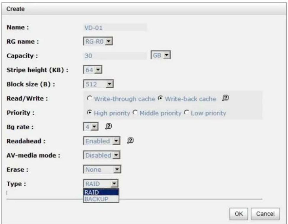
Figure 4.4.3.1

Caution
If shutdown or reboot the system when creating VD, the erase process will stop.
Step 2: Confirm page. Click "OK" if all setups are correct.
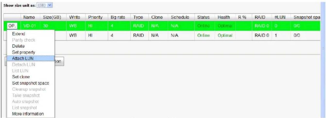
Figure 4.4.3.2
(Figure 4.4.3.2: Create a VD named "VD-01", from "RG-R0".)
Step 3: Done. View "Virtual disk" page.
- VD column description:
| The button includes the functions which can be executed. | |
| Name Virtual disk name. | |
| Size (GB) (MB) | Total capacity of the virtual disk. The unit can be displayed in GB or MB. |
| Write The right of virtual disk:“WT” → Write Through.“WB” → Write Back.“RO” → Read Only. | |
| Priority The priority of virtual disk:“HI” → Hlgh priority.“MD” → MiDdle priority.“LO” → LOw priority. | |
| Bg rate Background task priority:“4 / 3 / 2 / 1 / 0” → Default value is 4. The higher | |
| number the background priority of a VD is, the more background I/O will be scheduled to execute. | |
| Status The status of virtual disk:“Online” → The virtual disk is online.“Offline” → The virtual disk is offline.“Initiating” → The virtual disk is being initialized.“Rebuild” → The virtual disk is being rebuilt.“Migrate” → The virtual disk is being migrated.“Rollback” → The virtual disk is being rolled back.“Parity checking” → The virtual disk is being parity check. | |
| Type The type of virtual disk:“RAID” → the virtual disk is normal.“BACKUP” → the virtual disk is for clone usage. | |
| Clone The target name of virtual disk. | |
| Schedule | The clone schedule of virtual disk: |
| Health The health of virtual disk:“Optimal” → the virtual disk is working well and there is no failed disk in the RG.“Degraded” → At least one disk from the RG of the Virtual disk is failed or plugged out.“Failed” → the RAID group disk of the VD has single or multiple failed disks than its RAID level can recover from data loss.“Partially optimal” → the virtual disk has experienced recoverable read errors. After passing parity check, the health will become “Optimal”. | |
| R % | Ratio (%) of initializing or rebuilding. |
| RAID RAID level. | |
| # LUN | Number of LUN(s) that virtual disk is attached to. |
| Snapshot (GB) (MB) | The virtual disk size that is used for snapshot. The number means “Used snapshot space” / “Total snapshot space”.The unit can be displayed in GB or MB. |
| # Snapshot Number | Number of snapshot(s) that have been taken. |
| RG name The RG name of the virtual disk | |
• VD operation description:
| Create Create a virtual disk. | |
| Extend Extend the virtual disk capacity. | |
| Parity check | Execute parity check for the virtual disk. It supports RAID 3 / 5 / 6 / 30 / 50 / 60.Regenerate parity:“Yes” → Regenerate RAID parity and write.“No” → Execute parity check only and find mismatches. It will stop checking when mismatches count to 1 / 10 / 20 / ... / 100. |
| Delete Delete the virtual disk. | |
| Set property | Change the VD name, right, priority, bg rate and read ahead.Right:“WT” → Write Through.“WB” → Write Back. (Default)“RO” → Read Only.Priority:“HI” → HI gh priority. (Default)“MD” → MiDdle priority.“LO” → LOw priority.Bg rate:“4 / 3 / 2 / 1 / 0” → Default value is 4. The higher number the background priority of a VD is, the more background I/O will be scheduled to execute.Read ahead:“Enabled” → Enable disk read ahead. (Default)“Disabled” → Disable disk read ahead.AV-media mode:“Enabled” → Enable AV-media mode for optimizing videoediting. “Disabled” → Disable AV-media mode. (Default) Type: “RAI D” → the virtual disk is normal. (Default) “Backup” → the virtual disk is for clone usage. |
| Attach LUN Attach to a LUN. | |
| Detach LUN Detach to a LUN. | |
| List LUN List attached LUN(s). | |
| Set clone Set the target virtual disk for clone. | |
| Clear clone Clear clone function. | |
| Start clone Start clone function. | |
| Stop clone Stop clone function. | |
| Schedule clone | Set clone function by schedule. |
| Set snapshot space | Set snapshot space for taking snapshot. Please refer to next chapter for more detail. |
| Cleanup snapshot | Clean all snapshots of a VD and release the snapshot space. |
| Take snapshot | Take a snapshot on the virtual disk. |
| Auto snapshot | Set auto snapshot on the virtual disk. |
| List snapshot List all snapshots of the virtual disk. | |
| More information | Show virtual disk detail information. |
4.4.4 Snapshot
"Snapshot" can view the status of snapshot, create, and modify snapshots. Please refer to next chapter for more detail about snapshot concept. The following is an example to take a snapshot.
Step 1: Create snapshot space. In "/ Volume configuration / Virtual disk", Check to the gray button next to the VD number; click "Set snapshot space".
Step 2: Set snapshot space. Then click "OK". The snapshot space is created.

Figure 4.4.4.1
| Show size unit as: (GB) | ||||||||||||||||
| Name | Size(GB) | Write | Priority | Bg rate | Type | Clone | Schedule | Status | Health | R % | RAID | #LUN | Snapshot space(GB) | #Snapshot | RG | |
| OP. | VD-01 | 30 | WB | HI | 4 | RAID | N/A | N/A | Online | Optimal | RAID 0 | 0 | 1/15 | 0 | RG-R0 | |
| OP. | VD-02 | 20 | WB | HI | 4 | RAID | N/A | N/A | Online | Optimal | RAID 5 | 0 | 0/0 | 0 | RG-R5 | |
Figure 4.4.4.2
(Figure 4.4.4.2: "VD-01" snapshot space has been created, snapshot space is 15GB, and used 1GB for saving snapshot index.)
Step 3: Take a snapshot. In "/ Volume configuration / Snapshot", click "Take snapshot". It will link to next page. Enter a snapshot name.
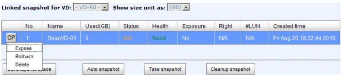
Figure 4.4.4.3
Step 4: Expose the snapshot VD. Check to the gray button next to the Snapshot VD number; click "Expose". Enter a capacity for snapshot VD. If size is zero, the exposed snapshot VD will be read only. Otherwise, the exposed snapshot VD can be read / written, and the size will be the maximum capacity for read / write.

Figure 4.4.4.4

Figure 4.4.4.5
(Figure 4.4.4.5: This is the snapshot list of "VD-01". There are two snapshots. Snapshot VD "SnapVD-01" is exposed as read-only, "SnapVD-02" is exposed as read-write.)
Step 5: Attach a LUN to a snapshot VD. Please refer to the next section for attaching a LUN.
Step 6: Done. Snapshot VD can be used.
- Snapshot column description:
| The button includes the functions which can be executed. | |
| Name Snapshot | VD name. |
| Used (GB) (MB) | The amount of snapshot space that has been used. The unit can be displayed in GB or MB. |
| Status The status of snapshot:“N/ A” → The snapshot is normal.“Replicated” → The snapshot is for clone or Replication usage.“Abort” → The snapshot is over space and abort. | |
| Health The health of snapshot: | |
| · “Good” → The snapshot is good.· “Failed” → The snapshot fails. | |
| Exposure Snapshot VD is exposed or not. | |
| Right The right of snapshot: · “Read-write” → The snapshot VD can be read / write. · “Read-only” → The snapshot VD is read only. | |
| # LUN Number of LUN(s) that snapshot VD is attached. | |
| Created time Snapshot VD created time. | |
- Snapshot operation description:
| Expose/Unexpose | Expose / unexpose the snapshot VD. |
| Rollback Rollback the snapshot VD. | |
| Delete Delete the snapshot VD. | |
| Attach Attach a LUN. | |
| Detach Detacha LUN. | |
| List LUN List attached LUN(s). | |
4.4.5 Logical unit
“Logical unit” can view, create, and modify the status of attached logical unit number(s) of each VD.
User can attach LUN by clicking the “Attach”. “Host” must enter with an iSCSI node name for access control, or fill-in wildcard “*”, which means every host can access the volume. Choose LUN number and permission, and then click “OK”.
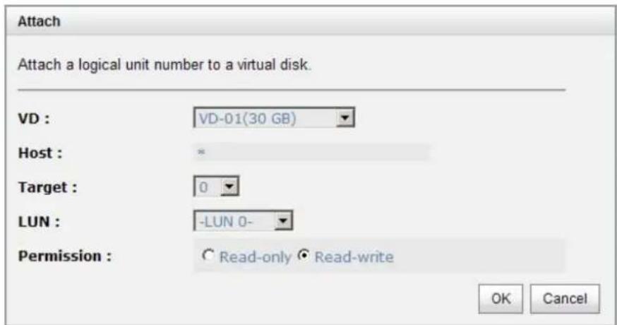
Figure 4.4.5.1

Figure 4.4.5.2
• LUN operation description:
| Attach Attach a logical unit number to a virtual disk. | |
| Detach Detach a logical unit number from a virtual disk. |
The matching rules of access control are followed from the LUN' created time; the earlier created LUN is prior to the matching rules. For example: there are 2 LUN rules for the same VD, one is “*”, LUN 0; and the other is “iqn.host1”, LUN 1. The host “iqn.host2” can login successfully because it matches the rule 1.
Wildcard “*” and “?” are allowed in this field. “*” can replace any word. “?” can replace only one character. For example:
"iqn.host?" → "iqn.host1" and "iqn.host2" are accepted. "iqn.host*" → "iqn.host1" and "iqn.host12345" are accepted.
This field can not accept comma, so "iqn.host1, iqn.host2" stands a long string, not 2 iqns.
4.4.6 Example
The following is an example to create volumes. This example is to create two VDs and set a global spare disk.
- Example
This example is to create two VDs in one RG, each VD shares the cache volume. The cache volume is created after system boots up automatically. Then set a global spare disk. Last, delete all of them.
Step 1: Create a RG (RAID group).
To create a RAID group, please follow the procedures:

Figure 4.4.6.1
- Select "/ Volume configuration / RAID group".
- Click "Create".
- Input a RG Name, choose a RAID level from the list, click "Select PD" to choose the RAID physical disks, then click "OK".
- Check the setting. Click "OK" if all setups are correct.
- Done. A RG has been created.
| Name | Total(GB) | Free(GB) | #PD | #VD | Status | Health | RAID | Current owner | Preferred owner | |
| OP. | RG-R5 | 931 | 931 | 3 | 0 | Online | Good | RAID 5 | Controller 1 | Controller 1 |
Figure 4.4.6.2
(Figure 4.4.6.2: Creating a RAID 5 with 3 physical disks, named "RG-R5").
Step 2: Create VD (Virtual Disk).
To create a data user volume, please follow the procedures.

Figure 4.4.6.3
- Select "/ Volume configuration / Virtual disk".
- Click "Create".
- Input a VD name, choose a RG Name and enter a size for this VD; decide the stripe height, block size, read / write mode, bg rate, and set priority, finally click "OK".
- Done. A VD has been created.
- Follow the above steps to create another VD.
| Show size unit as: (GB) | ||||||||||||||||
| Name | Size(GB) | Write | Priority | Bg rate | Type | Clone | Schedule | Status | Health | R % | RAID | #LUN | Snapshot space(GB) | #Snapshot | RG | |
| OP | VD-R5-1 | 50 | WB | HI | 4 | RAID | N/A | N/A | Initiating | Optimal | 9 | RAID 5 | 0 | 0/0 | 0 | RG-R5 |
| OP | VD-R5-2 | 64 | WB | HI | 4 | RAID | N/A | N/A | Initiating | Optimal | 0 | RAID 5 | 0 | 0/0 | 0 | RG-R5 |
Figure 4.4.6.4
(Figure 4.4.6.4: Creating VDs named "VD-R5-1" and "VD-R5-2" from RAID group "RG-R5", the size of "VD-R5-1" is 50GB, and the size of "VD-R5-2" is 64GB. There is no LUN attached.)
Step 3: Attach a LUN to a VD.
There are 2 methods to attach a LUN to a VD.
-
In "/ Volume configuration / Virtual disk", check the gray button next to the VD number; click "Attach LUN".
-
In "/ Volume configuration / Logical unit", click "Attach".
The procedures are as follows:

Figure 4.4.6.5
1. Select a VD.
- Input "Host" IQN, which is an iSCSI node name for access control, or fill-in wildcard "*", which means every host can access to this volume. Choose LUN and permission, and then click "OK".
- Done.
| Host | Target | LUN | Permission | VD name | #Session | |
| OP | * | 0 | 0 | Read-write | VD-R5-1 | 0 |
| OP | * | 1 | 1 | Read-write | VD-R5-2 | 0 |
Figure 4.4.6.6

Tips
The matching rules of access control are from the LUNs' created time, the earlier created LUN is prior to the matching rules.
Step 4: Set a global spare disk.
To set a global spare disk, please follow the procedures.
- Select "/ Volume configuration / Physical disk".
- Check the gray button next to the PD slot; click "Set global space".
- "Global spare" status is shown in "Usage" column.
| Slot | Size(GB) | RG | Status | Health | Usage | Vendor | Serial | Type | Write cache | Standby | Readahead | Command queuing | |
| OP | 1 | 465 | RG-R5 | Online | Good | RAID disk | SEAGATE | 3QM00X1W00009843LV6Z | SAS | Enabled | Disabled | Enabled | Enabled |
| OP | 2 | 465 | RG-R5 | Online | Good | RAID disk | SEAGATE | 9QMBKDSX000099445E69 | SAS | Enabled | Disabled | Enabled | Enabled |
| OP | 3 | 465 | RG-R5 | Online | Good | RAID disk | SEAGATE | 9QMBKV6R000099427KPJ | SAS | Enabled | Disabled | Enabled | Enabled |
| OP | 4 | 465 | Online | Good | Global spare | SEAGATE | 9QMBKEZW000099446C09 | SAS | Enabled | Disabled | Enabled | Enabled | |
Figure 4.4.6.7
(Figure 4.4.6.7: Slot 4 is set as a global spare disk.)
Step 5: Done.
Delete VDs, RG, please follow the below steps.
Step 6: Detach a LUN from the VD.
In "/ Volume configuration / Logical unit",
| Host | Target | LUN | Permission | VD name | #Session | |
| OP | - | 0 | 0 | Read-write | VD-R5-1 | 0 |
| Detach | 1 | 1 | Read-write | VD-R5-2 | 0 | |
Figure 4.4.6.8
- Check the gray button next to the LUN; click "Detach". There will pop up a confirmation page.
- Choose "OK".
- Done.
Step 7: Delete a VD (Virtual Disk).
To delete the virtual disk, please follow the procedures:
- Select "/ Volume configuration / Virtual disk".
- Check the gray button next to the VD number; click "Delete". There will pop up a confirmation page, click "OK".
- Done. Then, the VD is deleted.

Tips
When deleting VD directly, the attached LUN(s) of to this VD will be detached together.
Step 8: Delete a RG (RAID group).
To delete a RAID group, please follow the procedures:
- Select "/ Volume configuration / RAID group".
- Select a RG which all its VD are deleted, otherwise the this RG cannot be deleted.
- Check the gray button next to the RG number click "Delete".
- There will pop up a confirmation page, click "OK".
- Done. The RG has been deleted.

Tips
The action of deleting one RG will succeed only when all of the related VD(s) are deleted in this RG. Otherwise, user cannot delete this RG.
Step 9: Free a global spare disk.
To free a global spare disk, please follow the procedures.
- Select "/ Volume configuration / Physical disk".
- Check the gray button next to the PD slot; click "Set Free disk".
Step 10: Done, all volumes have been deleted.
4.5 Enclosure management
“Enclosure management” allows managing enclosure information including “Hardware monitor”, “UPS”, “SES”, and “S.M.A.R.T.”. For the enclosure management, there are many sensors for different purposes, such as temperature sensors, voltage sensors, hard disk status, fan sensors, power sensors, and LED status. Due to the different hardware characteristics among these sensors, they have different polling intervals. Below are the details of the polling time intervals:
- Temperature sensors: 1 minute.
- Voltage sensors: 1 minute.
- Hard disk sensors: 10 minutes.
- Fan sensors: 10 seconds. When there are 3 errors consecutively, system sends ERROR event log.
- Power sensors: 10 seconds, when there are 3 errors consecutively, system sends ERROR event log.
- LED status: 10 seconds.
| Hardware monitor | UPS | SES | S.M.A.R.T. |
Figure 4.5.1
4.5.1 Hardware monitor
“Hardware monitor” can view the information of current voltages and temperatures.

Figure 4.5.1.1
If "Auto shutdown" is checked, the system will shutdown automatically when voltage or temperature is out of the normal range. For better data protection, please check "Auto Shutdown".
For better protection and avoiding single short period of high temperature triggering auto shutdown, the system use multiple condition judgments to trigger auto shutdown, below are the details of when the Auto shutdown will be triggered.
- There are several sensors placed on systems for temperature checking. System will check each sensor for every 30 seconds. When one of these sensor is over high temperature threshold for continuous 3 minutes, auto shutdown will be triggered immediately.
- The core processor temperature limit is 80^ C. The iSCSI NIC temperature limit is 65^ C. The SAS expander and SAS controller temperature limit is 65^ C.
- If the high temperature situation doesn't last for 3 minutes, system will not trigger auto shutdown.
4.5.2 UPS
"UPS" can set up UPS (Uninterruptible Power Supply).
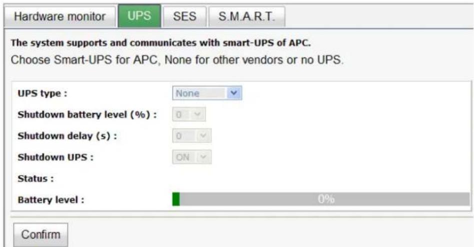
Figure 4.5.2.1
(Figure 4.5.2.1: Without UPS.)
Currently, the system only supports and communicates with smart-UPS of APC (American Power Conversion Corp.) UPS. Please review the details from the website: http://www.apc.com/.
First, connect the system and APC UPS via RS-232 for communication. Then set up the shutdown values (shutdown battery level %) when power is failed. UPS in other companies can work well, but they have no such communication feature with the system.

Figure 4.5.2.2
(Figure 4.5.2.2: With Smart-UPS.)
- UPS column description:
| UPS Type | Select UPS Type. Choose Smart-UPS for APC, None for other vendors or no UPS. |
| Shutdown Battery Level (%) | When below the setting level, system will shutdown. Setting level to “0” will disable UPS. |
| Shutdown Delay (s) | If power failure occurs, and system power can not recover, the system will shutdown. Setting delay to “0” will disable the function. |
| Shutdown UPS | Select ON, when power is gone, UPS will shutdown by itself after the system shutdown successfully. After power comes back, UPS will start working and notify system to boot up. OFF will not. |
| Status The status of UPS:“Detecting...”“Running”“Unable to detect UPS”“Communication lost”“UPS reboot in progress” | |
| • “UPS shutdown in progress”• “Batteries failed. Please change them NOW!” | |
| BatteryLevel (%) | Current power percentage of battery level. |
4.5.3 SES
SES represents SCSI Enclosure Services, one of the enclosure management standards. "SES configuration" can enable or disable the management of SES.

Figure 4.5.3.1
(Figure 4.5.1.1: Enable SES in LUN 0, and can be accessed from every host)
The SES client software is available at the following web site:
SANtools: http://www.santools.com/
4.5.4 Hard drive S.M.A.R.T.
S.M.A.R.T. (Self-Monitoring Analysis and Reporting Technology) is a diagnostic tool for hard drives to deliver warning of drive failures in advance. S.M.A.R.T. provides users chances to take actions before possible drive failure.
S.M.A.R.T. measures many attributes of the hard drive all the time and inspects the properties of hard drives which are close to be out of tolerance. The advanced notice of possible hard drive failure can allow users to back up hard drive or replace the hard drive. This is much better than hard drive crash when it is writing data or rebuilding a failed hard drive.
“S.M.A.R.T.” can display S.M.A.R.T. information of hard drives. The number is the current value; the number in parenthesis is the threshold value. The threshold values from different hard drive vendors are different; please refer to hard drive vendors' specification for details.
S.M.A.R.T. only supports SATA drives. SAS drives do not have this function now. It will show N/A in the web page for SAS drives.
| Hardware monitor | UPS | SES | S.M.A.R.T. | |||||
| Self-Monitoring Analysis and Reporting Technology(S.M.A.R.T). A diagnostic tool for hard drives to deliver warning of drive failures in advance. S.M.A.R.T. provides users chances to take actions before possible drive failure. Show information for: -Local- Temperature: (C) | ||||||||
| Slot | HDD type | Read error (rate) | Spin up (time) | Reallocated sector (count) | Seek error (rate) | Spin up (retries) | Calibration (retries) | Temperature(C) |
| 4 | SAS | N/A | N/A | N/A | N/A | N/A | N/A | 34 |
| 5 | SAS | N/A | N/A | N/A | N/A | N/A | N/A | 36 |
| 9 | SAS | N/A | N/A | N/A | N/A | N/A | N/A | 31 |
| 10 | SATA2 | 94(6) | 97(0) | 97(36) | 86(30) | 100(97) | N/A | 37 |
| 11 | SATA2 | 109(6) | 91(0) | 49(36) | 78(30) | 100(97) | N/A | 34 |
| 12 | SATA2 | 185(51) | 172(21) | 200(140) | 200(0) | 100(0) | 100(0) | 36 |
Figure 4.5.4.1 (SAS drives & SATA drives)
4.6 System maintenance
“Maintenance” allows the operations of system functions which include “System information” to show the system version and details, “Event log” to view system event logs to record critical events, “Upgrade” to the latest firmware, “Firmware synchronization” to synchronized firmware versions on both controllers, “Reset to factory default” to reset all controller configuration values to factory settings, “Import and export” to import and export all controller configuration to a file, and “Reboot and shutdown” to reboot or shutdown the system.
| System information | Event log | Upgrade | Firmware synchronization | Reset to factory default | Import and export | Reboot and shutdown |
Figure 4.6.1
4.6.1 System information
“System information” can display system information, including CPU type, installed system memory, firmware version, serial numbers of dual controllers, backplane ID, and system status.
| Item | Information |
| CPU type | XSC3-IOP8134x Family rev 9 (v5l) |
| System memory | ECC Unbuffered DDR-II 2048MB |
| Firmware version | DSN-6000 2.0.1 |
| Serial number | 001378BB0900 (Controller 1 : 500137800390AD98 , Controller 2 : 500137800390A5D8 ) |
| Backplane ID | DSN6000 |
| JBOD serial no. | No JBOD connected |
| Status | Normal |
| Replication | Activated. |
Figure 4.6.1.1
- Status description:
| Normal Dual controllers are in normal stage. | |
| Degraded One controller fails or has been plugged out. | |
| Lockdown The firmware of two controllers is different or the size of memory of two controllers is different. | |
| Single Single controller mode. |
4.6.2 Event log
"Event log" can view the event messages. Check the checkbox of INFO, WARNING, and ERROR to choose the level of event log display. Click "Download" button to save the whole event log as a text file with file name "log-ModelName-SerialNumber-Date-Time.txt". Click "Clear" button to clear all event logs. Click "Mute" button to stop alarm if system alerts.
| System information Event log Upgrade Firmware synchronization Reset to | ||
| Select event level of displayed event log INFO WARNING ERROR | ||
| << first < prev 1 2 3 4 5 6 7 8 9 10 next > last >> | ||
| Type | Time | Content |
| INFO | Tue, 11 Jan 2011 15:43:44 | [CTR1] admin login from 192.168.8.174 via Web UI |
| INFO | Tue, 11 Jan 2011 14:58:54 | [CTR1] admin login from 192.168.8.174 via Web UI |
| INFO | Tue, 11 Jan 2011 14:42:20 | [CTR1] admin login from 192.168.8.174 via Web UI |
| INFO | Tue, 11 Jan 2011 14:11:43 | [CTR1] Controller 1 restored to previous caching mode on failback. |
| INFO | Tue, 11 Jan 2011 14:11:19 | [CTR2] Battery backup feature is disabled. |
| INFO | Tue, 11 Jan 2011 14:11:08 | [CTR2] ECC memory is installed |
| INFO | Tue, 11 Jan 2011 14:11:11 | [CTR1] admin login from 192.168.8.174 via Web UI |
| INFO | Tue, 11 Jan 2011 14:10:47 | [CTR1] admin login from 192.168.156.10 via Web UI |
| INFO | Tue, 11 Jan 2011 14:10:33 | [CTR1] All volumes in controller 1 completed failover process. |
| INFO | Tue, 11 Jan 2011 14:10:33 | [CTR1] Controller 1 forced to adopt write-through mode on failover. |
| INFO | Tue, 11 Jan 2011 14:09:47 | [CTR2] All volumes in controller 2 completed failback process. |
| INFO | Tue, 11 Jan 2011 14:09:47 | [CTR2] Controller 2 restored to previous caching mode on failback. |
| INFO | Tue, 11 Jan 2011 14:09:25 | [CTR1] Battery backup feature is disabled. |
| INFO | Tue, 11 Jan 2011 14:09:14 | [CTR1] ECC memory is installed |
| INFO | Tue, 11 Jan 2011 14:08:34 | [CTR2] All volumes in controller 2 completed failover process. |
Figure 4.6.2.1
The event log is displayed in reverse order which means the latest event log is on the first / top page. The event logs are actually saved in the first four hard drives; each hard drive has one copy of event log. For one system, there are four copies of event logs to make sure users can check event log any time when there are failed disks.

Tips
Please plug-in any of the first four hard drives, then event logs can be saved and displayed in next system boot up. Otherwise, the event logs cannot be saved and would be disappeared.
4.6.3 Upgrade
"Upgrade" can upgrade firmware. Please prepare new firmware file named "xxxx.bin" in local hard drive, then click "Browse" to select the file. Click "Confirm", it will pop up a message "Upgrade system now? If you want to downgrade to the previous FW later (not recommend), please export your system configuration in advance", click "Cancel" to export system configuration in advance, then click "OK" to start to upgrade firmware.
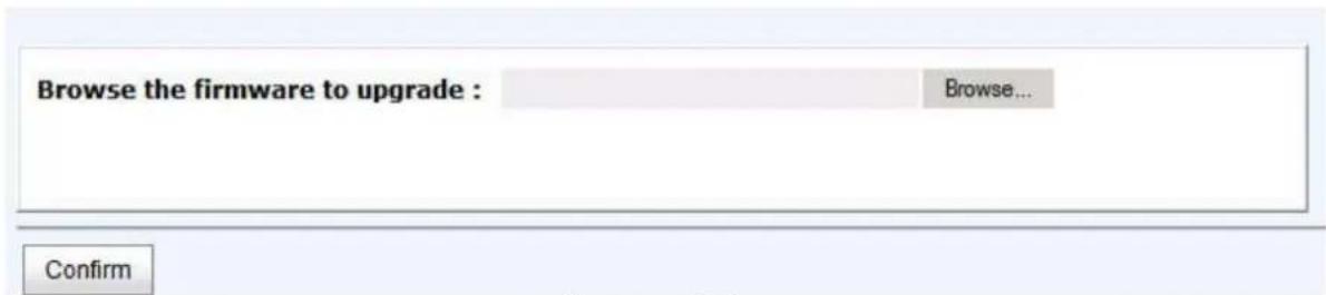
Figure 4.6.3.1
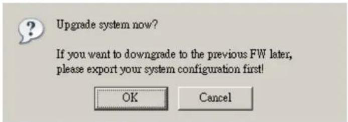
Figure 4.6.3.2
When upgrading, there is a progress bar running. After finished upgrading, the system must reboot manually to make the new firmware took effect.
4.6.4 Firmware synchronization
"Firmware synchronization" can synchronize the firmware version when controller 1 and controller 2's firmware are different. It will upgrade the firmware of slave controller to master ones no matter what the firmware version of slave controller is newer or older than master. In normal status, the firmware versions in controller 1 and 2 are the same as below figure.
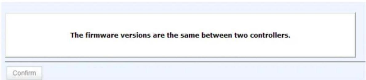
Figure 4.6.4.1
4.6.5 Reset to factory default
"Reset to factory default" allows user to reset IP SAN storage to factory default setting.

Figure 4.6.5.1
Reset to default value, the password is: 1234, and IP address to default 192.168.0.32
4.6.6 Import and export
"Import and export" allows user to save system configuration values: export, and apply all configuration: import. For the volume configuration setting, the values are available in export and not available in import which can avoid confliction / date-deleting between two IP SAN storages which mean if one system already has valuable volumes in the disks and user may forget and overwrite it. Use import could return to original configuration. If the volume setting was also imported, user's current volumes will be overwritten with different configuration.
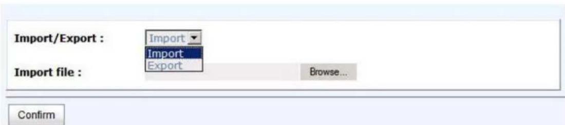
Figure 4.6.6.1
- Import: Import all system configurations excluding volume configuration.
- Export: Export all configurations to a file.

Caution
“Import” will import all system configurations excluding volume configuration; the current configurations will be replaced.
4.6.7 Reboot and shutdown
"Reboot and shutdown" can "Reboot" and "Shutdown" the system. Before power off, it's better to execute "Shutdown" to flush the data from cache to physical disks. The step is necessary for data protection.

Figure 4.6.7.1
4.7 Home/ Logout/ Mute
In the right-upper corner of web UI, there are 3 individual icons, "Home", "Logout", and "Mute".
natural_image
Green background with eight small icons including a folder, gear, and globe (no text or symbols)Figure 4.7.1
4.7.1 Home
Click "Home" to return to home page.
4.7.2 Logout
For security reason, please use "Logout" to exit the web UI. To re-login the system, please enter username and password again.
4.7.3 Mute
Click "Mute" to stop the alarm when error occurs.
Chapter 5 Advanced operations
5.1 Volume rebuild
If one physical disk of the RG which is set as protected RAID level (e.g.: RAID 3, RAID 5, or RAID 6) is FAILED or has been unplugged / removed, then the status of RG is changed to degraded mode, the system will search/detect spare disk to rebuild the degraded RG to a complete one. It will detect dedicated spare disk as rebuild disk first, then global spare disk.
D-LINK IP SAN storage supports Auto-Rebuild. Take RAID 6 for example:
- When there is no global spare disk or dedicated spare disk in the system, The RG will be in degraded mode and wait until (1) there is one disk assigned as spare disk, or (2) the failed disk is removed and replaced with new clean disk, then the Auto-Rebuild starts. The new disk will be a spare disk to the original RG automatically. If the new added disk is not clean (with other RG information), it would be marked as RS (reserved) and the system will not start "auto-rebuild". If this disk is not belonging to any existing RG, it would be FR (Free) disk and the system will start Auto-Rebuild. If user only removes the failed disk and plugs the same failed disk in the same slot again, the auto-rebuild will start running. But rebuilding in the same failed disk may impact customer data if the status of disk is unstable. D-LINK suggests all customers not to rebuild in the failed disk for better data protection.
- When there is enough global spare disk(s) or dedicated spare disk(s) for the degraded array, system starts Auto-Rebuild immediately. And in RAID 6, if there is another disk failure occurs during rebuilding, system will start the above Auto-Rebuild process as well. Auto-Rebuild feature only works at that the status of RG is "Online". It will not work at "Offline". Thus, it will not conflict with the "Online roaming" feature.
- In degraded mode, the status of RG is “Degraded”. When rebuilding, the status of RG / VD will be “Rebuild”, the column “R%” in VD will display the ratio in percentage. After complete rebuilding, the status will become “Online”. RG will become completely one.

Tips
“Set dedicated spare” is not available if there is no RG or only RG of RAID 0, JBOD, because user can not set dedicated spare disk to RAID 0 and JBOD.
Sometimes, rebuild is called recover; they are the same meaning. The following table is the relationship between RAID levels and rebuild.
- Rebuild operation description:
| RAID 0 | Disk striping. No protection for data. RG fails if any hard drive fails or unplugs. |
| RAID 1 Disk mirroring over 2 disks. RAID 1 allows one hard drive fails or unplugging. Need one new hard drive to insert to the system and rebuild to be completed. | |
| N-way mirror | Extension to RAID 1 level. It has N copies of the disk. N-way mirror allows N-1 hard drives failure or unplugging. |
| RAID 3 | Striping with parity on the dedicated disk. RAID 3 allows one hard drive failure or unplugging. |
| RAID 5 | Striping with interspersed parity over the member disks. RAID 5 allows one hard drive failure or unplugging. |
| RAID 6 2-dimensional parity protection over the member disks. RAID 6 allows two hard drives failure or unplugging. If it needs to rebuild two hard drives at the same time, it will rebuild the first one, then the other in sequence. | |
| RAID 0+1 | Mirroring of RAID 0 volumes. RAID 0+1 allows two hard drive failures or unplugging, but at the same array. |
| RAID 10 Strip ng over the member of RAID 1 volumes. RAID 10 allows two hard drive failure or unplugging, but in different arrays. | |
| RAID 30 Strip ng over the member of RAID 3 volumes. RAID 30 allows two hard drive failure or unplugging, but in different arrays. | |
| RAID 50 Strip ng over the member of RAID 5 volumes. RAID 50 allows two hard drive failures or unplugging, but in different arrays. | |
| RAID 60 Strip ng over the member of RAID 6 volumes. RAID 60 allows four hard drive failures or unplugging, every two in different arrays. | |
| JBOD | The abbreviation of “Just a Bunch Of Disks”. No data protection. RG fails if any hard drive failures or unplugs. |
5.2 RG migration
To migrate the RAID level, please follow below procedures.
- Select "/ Volume configuration / RAID group".
- Check the gray button next to the RG number; click "Migrate".
- Change the RAID level by clicking the down arrow to "RAID 5". There will be a pup-up which indicates that HDD is not enough to support the new setting of RAID level, click "Select PD" to increase hard drives, then click "OK" to go back to setup page. When doing migration to lower RAID level, such as the original RAID level is RAID 6 and user wants to migrate to RAID 0, system will evaluate whether this operation is safe or not, and appear a warning message of "Sure to migrate to a lower protection array?".

Figure 5.2.1
- Double check the setting of RAID level and RAID PD slot. If there is no problem, click "OK".
- Finally a confirmation page shows the detail of RAID information. If there is no problem, click "OK" to start migration. System also pops up a message of "Warning: power lost during migration may cause damage of data!" to give user warning. When the power is abnormally off during the migration, the data is in high risk.
- Migration starts and it can be seen from the "status" of a RG with "Migrating". In "/ Volume configuration / Virtual disk", it displays a "Migrating" in "Status" and complete percentage of migration in "R%".
| Show size unit as: (GB) | ||||||||||
| Name | Total(GB) | Free(GB) | #PD | #VD | Status | Health | RAID | Current owner | Preferred owner | |
| OP. | RG-R0->R5 | 1396 | 1386 | 4 | 1 | Migrating | Good | RAID 5 | Controller 1 | Controller 1 |
Figure 5.2.2
(Figure 5.2.2: A RAID 0 with 3 physical disks migrates to RAID 5 with 4 physical disks.)
| Show size unit as: (GB) | ||||||||||||||||
| Name | Size(GB) | Write | Priority | Big rate | Type | Clone | Schedule | Status | Health | R % | RAID | #LUN | Snapshot space(GB) | #Snapshot | RG | |
| OP. | VD-R0→R5 | 10 | WB | HI | 4 | RAID | N/A | N/A | Migrating | Optimal | 3 | RAND 5 | 0 | 0/0 | 0 | RG-R0→R5 |
Figure 5.2.3
To do migration, the total size of RG must be larger or equal to the original RG. It is not allow expanding the same RAID level with the same hard disks of original RG.
The below operations are not allowed when a RG is being migrated. System would reject these operations:
- Add dedicated spare.
- Remove a dedicated spare.
- Create a new VD.
- Delete a VD.
- Extend a VD.
- Scrub a VD.
- Perform another migration operation.
- Scrub entire RG.
- Take a snapshot.
- Delete a snapshot.
- Expose a snapshot.
- Rollback to a snapshot.

Caution
RG Migration cannot be executed during rebuilding or VD extension.
5.3 VD extension
To extend VD size, please follow the procedures.
- Select "/ Volume configuration / Virtual disk".
- Check the gray button next to the VD number; click "Extend".
- Change the size. The size must be larger than the original, and then click "OK" to start extension.

Figure 5.3.1
- Extension starts. If VD needs initialization, it will display an "Initiating" in "Status" and complete percentage of initialization in "R%".
| Show size unit as: (GB) | ||||||||||||||||
| Name | Size(GB) | Write | Priority | Bgr rate | Type | Clone | Schedule | Status | Health | R % | RAID | #LLIN | Snapshot space(GB) | #Snapshot | RG | |
| OP | VD-R0->R5 | 20 | WB | HI | 4 | RAID | N/A | N/A | Initiating | Optimal | 46 | RAID 5 | 0 | 0/0 | 0 | RG-R0->R5 |
Figure 5.3.2

Tips
The size of VD extension must be larger than original.

Caution
VD Extension cannot be executed during rebuilding or migration.
5.4 Snapshot
Snapshot-on-the-box captures the instant state of data in the target volume in a logical sense. The underlying logic is Copy-on-Write -- moving out the data which would be written to certain location where a write action occurs since the time of data capture. The certain location, named as "Snap VD", is essentially a new VD which can be attached to a LUN provisioned to a host as a disk like other ordinary VDs in the system. Rollback restores the data back to the state of any time which was previously captured in case for any unfortunate reason it might be (e.g. virus attack, data corruption, human errors and so on). Snap VD is allocated within the same RG in which the snapshot is taken, suggest to reserve 20% of RG size or more for snapshot space. Please refer to the following figure for snapshot concept.

flowchart
graph TD
    subgraph_DSN6000_series["DSN6000 series"]
        A["Working Volume"] --> B["Snapshot Volume 2pm"]
        B --> C["snapshot taken"]
        C --> D["MS Exchange Server"]
        D --> E["MS Virtual Snapshot Copy Services"]
    end

    subgraph_DSN6000_series["DSN6000 series"]
        F["Virus"] --> G["Corrupted Volume"]
        G --> H["Snapshot Volume 2pm"]
        H --> I["Transactional Consistency"]
        I --> J["MS Exchange Server"]
        J --> K["MS Virtual Snapshot Copy Services"]
    end

    subgraph_DSN6000_series["DSN6000 series"]
        L["Corrupted Volume"] --> M["Working Volume (Snapshot Volume 2pm)"]
        M --> N["Rollback"]
        N --> O["MS Exchange Server"]
        O --> P["MS Virtual Snapshot Copy Services"]
    end

    style DSN6000_series fill:#f9f9f9,stroke:#333
    style DSN6000_series fill:#e6f7ff,stroke:#333
    style DSN6000_series fill:#e6f7ff,stroke:#333
    style DSN6000_series fill:#e6f7ff,stroke:#333
    style DSN6000_series fill:#e6f7ff,stroke:#333
    style DSN6000_series fill:#e6f7ff,stroke:#333
Figure 5.4.1
5.4.1 Create snapshot volume
To take a snapshot of the data, please follow the procedures.
- Select "/ Volume configuration / Virtual disk".
- Check the gray button next to the VD number; click "Set snapshot space".
- Set up the size for snapshot. The minimum size is suggested to be 20% of VD size, and then click "OK". It will go back to the VD page and the size will show in snapshot column. It may not be the same as the number entered because some size is reserved for snapshot internal usage. There will be 2 numbers in "Snapshot" column. These numbers mean "Used snapshot space" and "Total snapshot space".
- There are two methods to take snapshot. In "/ Volume configuration / Virtual disk", check the gray button next to the VD number; click "Take snapshot". Or in "/ Volume configuration / Snapshot", click "Take snapshot".
- Enter a snapshot name, and then click "OK". A snapshot VD is created.
- Select "/ Volume configuration / Snapshot" to display all snapshot VDs taken from the VD.
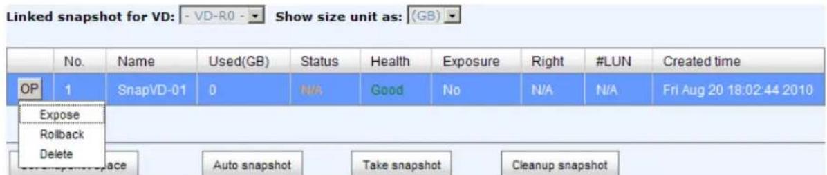
Figure 5.4.1.1
-
Check the gray button next to the Snapshot VD number; click "Expose". Enter a capacity for snapshot VD. If size is zero, the exposed snapshot VD is read only. Otherwise, the exposed snapshot VD can be read / written, and the size maximum capacity to read / write.
-
Attach a LUN to the snapshot VD. Please refer to the previous chapter for attaching a LUN.
-
Done. It can be used as a disk.

Figure 5.4.1.2
(Figure 5.4.1.2: This is the snapshot list of "VD-01". There are two snapshots. Snapshot VD "SnapVD-01" is exposed as read-only, "SnapVD-02" is exposed as read-write.)
- There are two methods to clean all snapshots. In “/ Volume configuration / Virtual disk”, check the gray button next to the VD number; click “Cleanup snapshot”. Or in “/ Volume configuration / Snapshot”, click “Cleanup”.
- "Cleanup snapshot" will delete all snapshots of the VD and release snapshot space.
5.4.2 Auto snapshot
The snapshot copies can be taken manually or by schedule such as hourly or daily. Please follow the procedures.
- There are two methods to set auto snapshot. In "/ Volume configuration / Virtual disk", check the gray button next to the VD number; click "Auto snapshot". Or in "/ Volume configuration / Snapshot", click "Auto snapshot".
- The auto snapshot can be set monthly, weekly, daily, or hourly.
- Done. It will take snapshots automatically.

Figure 5.4.2.1
(Figure 5.4.2.1: It will take snapshots every month, and keep the last 32 snapshot copies.)

Tips
Daily snapshot will be taken at every 00:00. Weekly snapshot will be taken every Sunday 00:00. Monthly snapshot will be taken every first day of month 00:00.
5.4.3 Rollback
The data in snapshot VD can rollback to original VD. Please follow the procedures.
- Select "/ Volume configuration / Snapshot".
- Check the gray button next to the Snap VD number which user wants to rollback the data; click "Rollback".
- Done, the data in snapshot VD is rollback to original VD.

Caution
Before executing rollback, it is better to dismount file system for flushing data from cache to disks in OS first. System sends pop-up message when user executes rollback function.
5.4.4 Snapshot constraint
D-LINK snapshot function applies Copy-on-Write technique on UDV/VD and provides a quick and efficient backup methodology. When taking a snapshot, it does not copy any data at first time until a request of data modification comes in. The snapshot copies the original data to snapshot space and then overwrites the original data with new changes. With this technique, snapshot only copies the changed data instead of copying whole data. It will save a lot of disk space.
- Create a data-consistent snapshot
Before using snapshot, user has to know why sometimes the data corrupts after rollback of snapshot. Please refer to the following diagram.
When user modifies the data from host, the data will pass through file system and memory of the host (write caching). Then the host will flush the data from memory to physical disks, no matter the disk is local disk (IDE or SATA), DAS (SCSI or SAS), or SAN (fibre or iSCSI). From the viewpoint of storage device, it can not control the behavior of host side. This case may be happens. If user takes a snapshot, some data is still in memory and not flush to disk. Then the snapshot may have an incomplete image of original data. The problem does not belong to the storage device. To avoid this data inconsistent issue between snapshot and original data, user has to make the operating system flush the data from memory of host (write caching) into disk before taking snapshot.

flowchart
graph TD
    A["User modified data"] -->|I/O| B["File System"]
    B -->|I/O| C["Memory (cache)"]
    C -->|I/O| D["Physical disk (SATA)"]
    C --> E["Physical disk (iSCSI)"]
    C --> F["Physical disk (SAS or Fibre)"]
Figure 5.4.4.1
On Linux and UNIX platform, a command named sync can be used to make the operating system flush data from write caching into disk. For Windows platform, Microsoft also provides a tool – sync, which can do exactly the same thing as the sync command in Linux/UNIX. It will tell the OS to flush the data on demand. For more detail about sync tool, please refer to: http://technet.microsoft.com/en-us/sysinternals/bb897438.aspx
Besides the sync tool, Microsoft develops VSS (volume shadow copy service) to prevent this issue. VSS is a mechanism for creating consistent point-in-time copies of data known as shadow copies. It is a coordinator between backup software, application (SQL or Exchange...) and storages to make sure the snapshot without the problem inconsistent. For more detail about the VSS, please refer to http://technet.microsoft.com/en-us/library/cc785914.aspx. DSN-6110/6120 can support Microsoft VSS.
• What if the snapshot space is over?
Before using snapshot, a snapshot space is needed from RG capacity. After a period of working snapshot, what if the snapshot size over the snapshot space of user defined? There are two different situations:
-
If there are two or more snapshots existed, the system will try to remove the oldest snapshots (to release more space for the latest snapshot) until enough space is released.
-
If there is only one snapshot existed, the snapshot will fail. Because the snapshot space is run out.
For example, there are two or more snapshots existed on a VD and the latest snapshot keeps growing. When it comes to the moment that the snapshot space is run out, the system will try to remove the oldest snapshot to release more space for the latest snapshot usage. As the latest snapshot is growing, the system keeps removing the old snapshots. When it comes that the latest snapshot is the only one in system, there is no more snapshot space which can be released for incoming changes, then snapshot will fail.
• How many snapshots can be created on a VD
There are up to 32 snapshots can be created on a UDV/VD. What if the 33rd snapshot has been taken? There are two different situations:
-
If the snapshot is configured as auto snapshot, the latest one (the 33rd snapshot) will replace the oldest one (the first snapshot) and so on.
-
If the snapshot is taken manually, when taking the 33rd snapshot will fail and a warning message will be showed on Web UI.
- Rollback / Delete snapshot
When a snapshot has been rollbacked, the other snapshots which are earlier than it will also be removed. But the rest snapshots will be kept after rollback. If a snapshot has been deleted, the other snapshots which are earlier than it will also be deleted. The space occupied by these snapshots will be released after deleting.
5.5 Disk roaming
Physical disks can be re-sequenced in the same system or move all physical disks in the same RAID group from system-1 to system-2. This is called disk roaming. System can execute disk roaming online. Please follow the procedures.
- Select "/ Volume configuration / RAID group".
- Check the gray button next to the RG number; click "Deactivate".
- Move all PDs of the RG to another system.
- Check the gray button next to the RG number; click "Activate".
- Done.
Disk roaming has some constraints as described in the followings:
- Check the firmware version of two systems first. It is better that either systems have the same firmware version or system-2 firmware version is newer.
- All physical disks of the RG should be moved from system-1 to system-2 together. The configuration of both RG and VD will be kept but LUN configuration will be cleared in order to avoid conflict with system-2's original setting.
5.6 VD clone
The user can use VD clone function to backup data from source VD to target VD, set up backup schedule, and deploy the clone rules.
The procedures of VD clone are on the following:
- Copy all data from source VD to target VD at the beginning (full copy).
- Use Snapshot technology to perform the incremental copy afterwards. Please be fully aware that the incremental copy needs to use snapshot to compare the data difference. Therefore, the enough snapshot space for VD clone is very important.
The following contents will take an example of a RAID 5 virtual disk (SourceVD_Raid5) clone to RAID 6 virtual disk (TargetVD_Raid6).
- Start VD clone
- Create a RAID group (RG) in advance.
| Show size unit as: (GB) | ||||||||||
| Name | Total(GB) | Free(GB) | #PD | #VD | Status | Health | RAID | Current owner | Preferred owner | |
| OP. | RG-R5 | 931 | 931 | 3 | 0 | Online | Good | RAID 5 | Controller 1 | Controller 1 |
| OP. | RG-R6 | 931 | 931 | 4 | 0 | Online | Good | RAID 6 | Controller 1 | Controller 1 |
Figure 5.6.1
- Create two virtual disks (VD) "SourceVD_R5" and "TargetVD_R6". The raid type of backup target needs to be set as "BACKUP".

Figure 5.6.2
- Here are the objects, a Source VD and a Target VD. Before starting clone process, it needs to deploy the VD Clone rule first. Click "Configuration".
| Show size unit as: (GB) | ||||||||||||||||
| Name | Size(GB) | Write | Priority | Bg rate | Type | Clone | Schedule | Status | Health | R % | RAID | #LLIN | Snapshot space(GB) | #Snapshot | RG | |
| OP | SourceVD_R5 | 20 | WB | HI | 4 | RAID | N/A | N/A | Online | Optimal | RAID 5 | 0 | 0/0 | 0 | RG-R5 | |
| OP | TargetVD_R6 | 20 | WB | HI | 4 | BACKUP | N/A | N/A | Online | Optimal | RAID 6 | 0 | 0/0 | 0 | RG-R6 | |
Figure 5.6.3
- There are three clone configurations, describe on the following.

Figure 5.6.4
- Snapshot space:
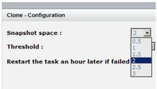
Figure 5.6.4
This setting is the ratio of source VD and snapshot space. The default ratio is 2 to 1. It means when the clone process is starting, the system will automatically use the free RG space to create a snapshot space which capacity is double the source VD.
• Threshold: (The setting will be effective after enabling schedule clone)

Figure 5.6.5
The threshold setting will monitor the usage amount of snapshot space. When the used snapshot space achieves its threshold, system will automatically take a clone snapshot and start VD clone process. The purpose of threshold could prevent the incremental copy fail immediately when running out of snapshot space.
For example, the default threshold is 50%. The system will check the snapshot space every hour. When the snapshot space is used over 50%, the system will synchronize the source VD and target VD automatically. Next time, when the rest snapshot space has been used 50%, in other words, the total snapshot space has been used 75%, the system will synchronize the source VD and target VD again.
- Restart the task an hour later if failed: (The setting will be effective after enabling schedule clone)

Figure 5.6.6
When running out of snapshot space, the VD clone process will be stopped because there is no more available snapshot space. If this option has been checked, system will clear the snapshots of clone in order to release snapshot space automatically, and the VD clone will restart the task after an hour. This task will start a full copy.
- After deploying the VD clone rule, the VD clone process can be started now. Firstly, Click "Set clone" to set the target VD at the VD name "SourceVD_R5".

Figure 5.6.7
- Select the target VD. Then click "Confirm".

Figure 5.6.8
- Now, the clone target "TargetVD_R6" has been set.
| Name | Size(GB) | Write | Priority | Bg rate | Type | Clone | Schedule | |
| OP. | SourceVD_R5 | 20 | WB | HI | 4 | RAID | TargetVD_R6 | N/A |
| OP. | TargetVD_R6 | 20 | WB | HI | 4 | BACKUP | N/A | N/A |
Figure 5.6.9
- Click "Start clone", the clone process will start.
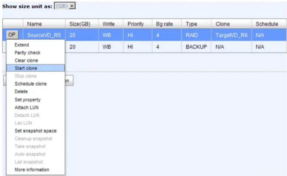
Figure 5.6.10
- The default setting will create a snapshot space automatically which the capacity is double size of the VD space. Before starting clone, system will initiate the snapshot space.
| Show size unit as: (GB) | ||||||||||||||||
| Name | Size(GB) | Write | Priority | Bg rate | Type | Clone | Schedule | Status | Health | R % | RAID | #LUN | Snapshot space(GB) | #Snapshot | RG | |
| OP | SourceVD_R5 | 20 | WB | HI | 4 | RAID | TargetvD_R6 | N/A | Initiating | Optimal | 33 | RAID 5 | 0 | 1/41 | 1 | RG-R5 |
| OP | TargetV/D_R6 | 20 | WB | HI | 4 | BACKUP | N/A | N/A | Online | Optimal | RAID 8 | 0 | 0/0 | 0 | RG-R5 | |
Figure 5.6.11
- After initiating the snapshot space, it will start cloning.
| Show size unit as: (GB) | ||||||||||||||||
| Name | Size(GB) | Write | Priority | Bg rate | Type | Clone | Schedule | Status | Health | R % | RAID | #LUN | Snapshot space(GB) | #Snapshot | RG | |
| OP | SourceVD_R5 | 20 | WB | HI | 4 | RAID | TargetVD_R5 | N/A | Cloning | Optimal | 37 | RAID 5 | 0 | 1/41 | 1 | RG-R5 |
| OP | TargetVD_R6 | 20 | WB | HI | 4 | BACKUP | N/A | N/A | Online | Optimal | RAID 6 | 0 | 0.0 | 0 | RG-R6 | |
Figure 5.6.12
- Click "Schedule clone" to set up the clone by schedule.

Figure 5.6.13
- There are "Set Clone schedule" and "Clear Clone schedule" in this page. Please remember that "Threshold" and "Restart the task an hour later if failed" options in VD configuration will take effect after clone schedule has been set.

Figure 5.6.14
- Run out of snapshot space while VD clone
While the clone is processing, the increment data of this VD is over the snapshot space. The clone will complete, but the clone snapshot will fail. Next time, when trying to start clone, it will get a warning message "This is not enough of snapshot space for the operation". At this time, the user needs to clean up the snapshot space in order to operate
the clone process. Each time the clone snapshot failed, it means that the system loses the reference value of incremental data. So it will start a full copy at next clone process.
When running out of snapshot space, the flow diagram of VD clone procedure will be like the following.
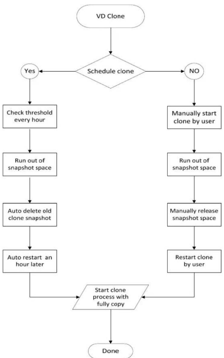
flowchart
graph TD
    A["VD Clone"] --> B{Schedule clone}
    B -->|Yes| C["Check threshold every hour"]
    B -->|No| D["Manually start clone by user"]
    C --> E["Run out of snapshot space"]
    E --> F["Auto delete old clone snapshot"]
    F --> G["Auto restart an hour later"]
    G --> H["Start clone process with fully copy"]
    D --> I["Run out of snapshot space"]
    I --> J["Manually release snapshot space"]
    J --> K["Restart clone by user"]
    K --> H
    H --> L["Done"]
Figure 5.6.15
5.7 SAS JBOD expansion
5.7.1 Connecting JBOD
D-LINK DSN-6000 series support up to 4 additional SAS/SATA JBODs for capacity expansion. When connecting to a dual-controller JBOD, it will display in "Show PD for:" of "/ Volume configuration / Physical disk". For example, Local, JBOD 1 (DSN-6020), JBOD 2 (DSN-6020), ...etc. Local means disks in local controller, and so on. The hard drives in JBOD can be used as local disks.
“/ Enclosure management / Hardware monitor” can display the hardware status of SAS JBODs.
“/ Enclosure management / S.M.A.R.T.” can display S.M.A.R.T. information of all PDs, including Local and all SAS JBODs.
SAS JBOD expansion has some constraints as described in the followings:
1 User could create RAID group among multiple chassis, max number of disks in a single RAID group is 32.
2 Global spare disk can support all RAID groups which located in the different chassis.
3 When support SATA drives for the redundant JBOD model, the SATA bridge board is required.
4 The following table is the maximum JBOD numbers and maximum HDD numbers with different chassises can be cascaded.
| RAID Storage System | Dual controllers + Dual JBODDSN-6120 |
| DSN-6020 no. | 4 |
| Max HDD no. | 60 |
5.7.2 Upgrade firmware of JBOD
To upgrade the firmware of JBOD, please follow the procedures.
1 There is a hidden web page for JBOD firmware upgrade. Please login Web UI as username admin first, and then add this URL to the browser. (http://Management IP/jbod_upg.php), for example:
http://192.168.10.50/jbod_upg.php
FOLLOW THE STEPS TO UPGRADE THE FIRMWARE OF JBOD

Figure 5.7.2.1
2 Choose a JBOD which wants to upgrade.
3 Please prepare new firmware file in local hard drive, then click "Browse" to select the file. Click "Confirm".
4 After finished upgrading, the system must reboot manually to make the new firmware took effect.
5.8 MPIO and MC/ S
These features come from iSCSI initiator. They can be setup from iSCSI initiator to establish redundant paths for sending I/O from the initiator to the target.
- MPIO: In Microsoft Windows server base system, Microsoft MPIO driver allows initiators to login multiple sessions to the same target and aggregate the duplicate devices into a single device. Each session to the target can be established using different NICs, network infrastructure and target ports. If one session fails, then another session can continue processing I/O without interruption to the application.
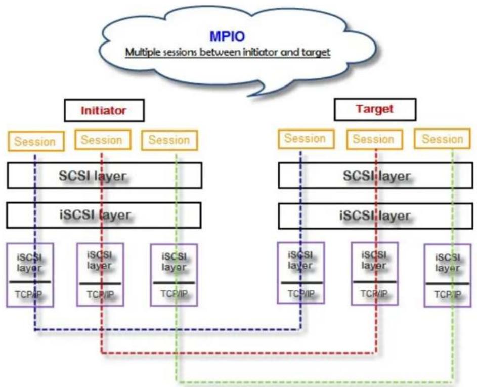
flowchart
graph TD
    A["MPIO Multiple sessions between initiator and target"] --> B["Initiator"]
    A --> C["Target"]
    B --> D["Session"]
    B --> E["Session"]
    B --> F["Session"]
    D --> G["SCSI layer"]
    E --> H["iSCSI layer"]
    F --> I["iSCSI layer"]
    G --> J["iSCSI layer"]
    H --> K["iSCSI layer"]
    I --> L["iSCSI layer"]
    J --> M["iSCSI layer"]
    K --> N["TCP/IP"]
    L --> O["TCP/IP"]
    M --> P["TCP/IP"]
    N --> Q["TCP/IP"]
    O --> R["TCP/IP"]
    P --> S["TCP/IP"]
    Q --> T["TCP/IP"]
    R --> U["TCP/IP"]
    S --> V["TCP/IP"]
    T --> W["TCP/IP"]
    U --> X["TCP/IP"]
    V --> Y["TCP/IP"]
    W --> Z["TCP/IP"]
    X --> AA["TCP/IP"]
    Y --> AB["TCP/IP"]
Figure 5.8.1
- MC/ S: MC/S (Multiple Connections per Session) is a feature of iSCSI protocol, which allows combining several connections inside a single session for performance and failover purposes. In this way, I/O can be sent on any TCP/IP connection to the target. If one connection fails, another connection can continue processing I/O without interruption to the application.

flowchart
graph TD
    A["MC/S Multiple Connections per Session"] --> B["Initiator"]
    A --> C["Target"]
    B --> D["Session"]
    D --> E["SCSI layer"]
    E --> F["iSCSI layer"]
    F --> G["iSCSI layer"]
    G --> H["TCP/IP"]
    F --> I["iSCSI layer"]
    I --> J["TCP/IP"]
    F --> K["iSCSI layer"]
    K --> L["TCP/IP"]
    C --> M["Session"]
    M --> N["SCSI layer"]
    N --> O["iSCSI layer"]
    O --> P["TCP/IP"]
    N --> Q["iSCSI layer"]
    Q --> R["TCP/IP"]
    O --> S["iSCSI layer"]
    S --> T["TCP/IP"]
    style A fill:#f9f,stroke:#333
    style C fill:#f9f,stroke:#333
Figure 5.8.2
Difference:
MC/S is implemented on iSCSI level, while MPIO is implemented on the higher level. Hence, all MPIO infrastructures are shared among all SCSI transports, including Fiber Channel, SAS, etc. MPIO is the most common usage across all OS vendors. The primary difference between these two is which level the redundancy is maintained. MPIO creates multiple iSCSI sessions with the target storage. Load balance and failover occurs between the multiple sessions. MC/S creates multiple connections within a single iSCSI session to manage load balance and failover. Notice that iSCSI connections and sessions are different than TCP/IP connections and sessions. The above figures describe the difference between MPIO and MC/S.
There are some considerations when user chooses MC/S or MPIO for multipathing.
- If user uses hardware iSCSI off-load HBA, then MPIO is the only one choice.
-
If user needs to specify different load balance policies for different LUNs, then MPIO should be used.
-
If user installs anyone of Windows XP, Windows Vista or Windows 7, MC/S is the only option since Microsoft MPIO is supported Windows Server editions only.
- MC/S can provide higher throughput than MPIO in Windows system, but it consumes more CPU resources than MPIO.
5.9 Trunking and LACP
Link aggregation is the technique of taking several distinct Ethernet links to let them appear as a single link. It has a larger bandwidth and provides the fault tolerance ability. Beside the advantage of wide bandwidth, the I/O traffic remains operating until all physical links fail. If any link is restored, it will be added to the link group automatically. D-LINK implements link aggregation as LACP and Trunking.
- LACP (IEEE 802.3ad): The Link Aggregation Control Protocol (LACP) is a part of IEEE specification 802.3ad. It allows bundling several physical ports together to form a single logical channel. A network switch negotiates an automatic bundle by sending LACP packets to the peer. Theoretically, LACP port can be defined as active or passive. D-LINK IP SAN Storage implements it as active mode which means that LACP port sends LACP protocol packets automatically. Please notice that using the same configurations between D-LINK IP SAN Storage and gigabit switch.
The usage occasion of LACP:
A. It's necessary to use LACP in a network environment of multiple switches. When adding new devices, LACP will separate the traffic to each path dynamically.

flowchart
graph TD
    A["Computer 1"] --> B["MPIOor MC/S"]
    C["Computer 2"] --> B
    D["Computer 3"] --> B
    E["Computer 4"] --> B
    F["Computer 5"] --> B
    G["Computer 6"] --> B
    H["Computer 7"] --> B
    I["Computer 8"] --> B
    J["Computer 9"] --> B
    K["Computer 10"] --> B
    L["Computer 11"] --> B
    M["Computer 12"] --> B
    N["LACP"] --> B
    O["DSN6000 Series"] --> P["Computer 1"]
    O --> Q["Computer 2"]
    O --> R["Computer 3"]
    O --> S["Computer 4"]
    O --> T["Computer 5"]
    O --> U["Computer 6"]
    style O fill:#f9f,stroke:#333,stroke-width:2px
Figure 5.9.1
- Trunking (Non-protocol): Defines the usage of multiple iSCSI data ports in parallel to increase the link speed beyond the limits of any single port.
The usage occasion of Trunking:
A. This is a simple SAN environment. There is only one switch to connect the server and storage. And there is no extra server to be added in the future.
B. There is no idea of using LACP or Trunking, uses Trunking first.
C. There is a request of monitoring the traffic on a trunk in switch.

flowchart
graph TD
    A["Application server"] --> B["MC/S or MPIO"]
    A --> C["Trunking"]
    B --> D["DSN6000 Series"]
    C --> D
    D --> E["Computer"]
    D --> F["Computer"]
Figure 5.9.2

Caution
Before using trunking or LACP, the gigabit switch must support trunking or LACP and enabled. Otherwise, host can not connect the link with storage device.
5.10 Dual controllers (only for DSN-6120)
5.10.1 Perform I/O
Please refer to the following topology and have all the connections ready. To perform I/O on dual controllers, server/host should setup MPIO. MPIO policy will keep I/O running and prevent fail connection with single controller failure.
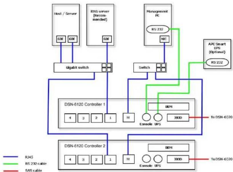
flowchart
graph TD
    A["Host / Server"] -->|GDE GDE| B["ugabit switch"]
    C["ISNS server (Recommended)"] -->|GDE| B
    D["Management PC"] -->|RS 232| E["Switch"]
    F["APC Smart UPS (Optional) RS 232"] -->|RS 232| E
    B --> G["DSN-6120 Controller 1"]
    E --> H["DSN-6120 Controller 2"]
    G --> I["4 3 2 1 M Console UPS"]
    H --> J["4 3 2 1 M Console UPS"]
    I --> K["To DSN-6020"]
    J --> L["To DSN-6020"]
    K --> M["RS45"]
    K --> N["RS 232 cable"]
    K --> O["SAS cable"]
Figure 5.10.1.1
5.10.2 Ownership
When creating RG, it will be assigned with a preferred owner, the default owner is controller 1. To change the RG ownership, please follow the procedures.
1 Select "/ Volume configuration / RAID group".
2 Check the gray button next to the RG name; click "Set preferred owner".
3 The ownership of the RG will be switched to the other controller.
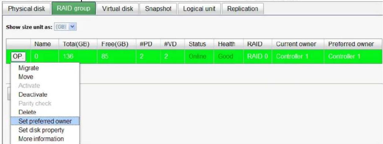
Figure 5.10.2.1

Figure 5.10.2.2
(Figure 5.10.2.2: The RG ownership is changed to the other controller.)
5.10.3 Controller status
There are four statuses described on the following. It can be found in “/ System maintenance / System information”.
- Normal: Dual controller mode. Both of controllers are functional.
- Degraded: Dual controller mode. When one controller fails or has been plugged out, the system will turn to degraded. In this stage, I/O will force to write through for protecting data and the ownership of RG will switch to good one. For example: if controller 1 which owns the RG1 fails accidentally, the ownership of RG1 will be switched to controller 2 automatically. And the system and data can keep working well. After controller 1 is fixed or replaced, The current owner of all RGs will be assigned back to their preferred owner.
- Lockdown: Dual controller mode. The firmware of two controllers is different or the size of memory of two controllers is different. In this stage, only master controller can work and I/O will force to write through for protecting data.
- Single: Single controller mode. In the stage, the controller must stay in slot A. Multiplexer boards for SATA drives are not necessary. The differences between single and degraded are described on the following. There is no error message for inserted one controller only. I/O will not force to write through. And there is no ownership of RG. Single controller mode can be upgraded to dual controller mode, please contact the distributor for upgradable.
In addition, iSNS server is recommended. It's important for keeping I/O running smoothly when RG ownership is switching or single controller is failed. Without iSNS server, when controller 1 fails, the running I/O from host to controller 1 may fail because the time which host switches to the new portal is slower than I/O time out. With iSNS server, this case would not happen.
5.11 Replication
Replication function will help users to replicate data easily through LAN or WAN from one IP SAN storage to another.
The procedures of Replication are on the following:
- Copy all data from source VD to target VD at the beginning (full copy).
- Use Snapshot technology to perform the incremental copy afterwards. Please be fully aware that the incremental copy needs to use snapshot to compare the data difference. Therefore, the enough snapshot space for VD clone is very important.
- Setup the Replication port on the source IP SAN storage
The Replication uses the last iSCSI port on the controller to replicate the data. That is the forth iSCSI port on DSN-6110/ 6120. When the iSCSI is configured as Replication port, it is no longer available for the host to connected as iSCSI port until it is configured as the normal iSCSI port again.
- In the operation menu of the last iSCSI port on the controller, select "Enable Replication" to set this port as the Replication port. The last iSCSI port on controller 2 will also be set as the Replication port automatically at the same time.

Figure 5.11.1
- The setting can be reverted by selecting "Disable Replication" in the menu.

Figure 5.11.2
- If you want the replication port to be on special VLAN section, you may assign VLAN ID to the replication port. The setting will automatically duplicate to the other controller.
- Create backup VD on the target IP SAN storage
- Before creating the replication job on the source IP SAN storage, user has to create a virtual disk on the target IP SAN storage and set the type of the VD as "Backup".

Figure 5.11.4
- The backup VD needs to be attached to a LUN ID first before creating replication job.
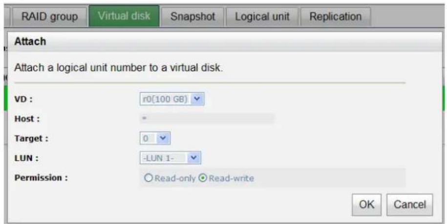
Figure 5.11.5
- Create replication job on the source IP SAN storage
- Click "Create" to create a new replication job.

Figure 5.11.6
- Select the source VD which will be replicated to the target IP SAN storage and click "Next".

Figure 5.11.7

Tips
If the message displays that there is not enough space for creation, please refer to the section of Configure the snapshot space below for solution.
- Enter the IP address of iSCSI port on controller 1 of the target IP SAN storage. Click "Next" to continue.

Figure 5.11.8
- The Replication uses standard iSCSI protocol for data replication. User has to log on the iSCSI node to create the iSCSI connection for the data transmission. Enter the CHAP information if necessary and select the target node to log no. Click "Next" to continue.
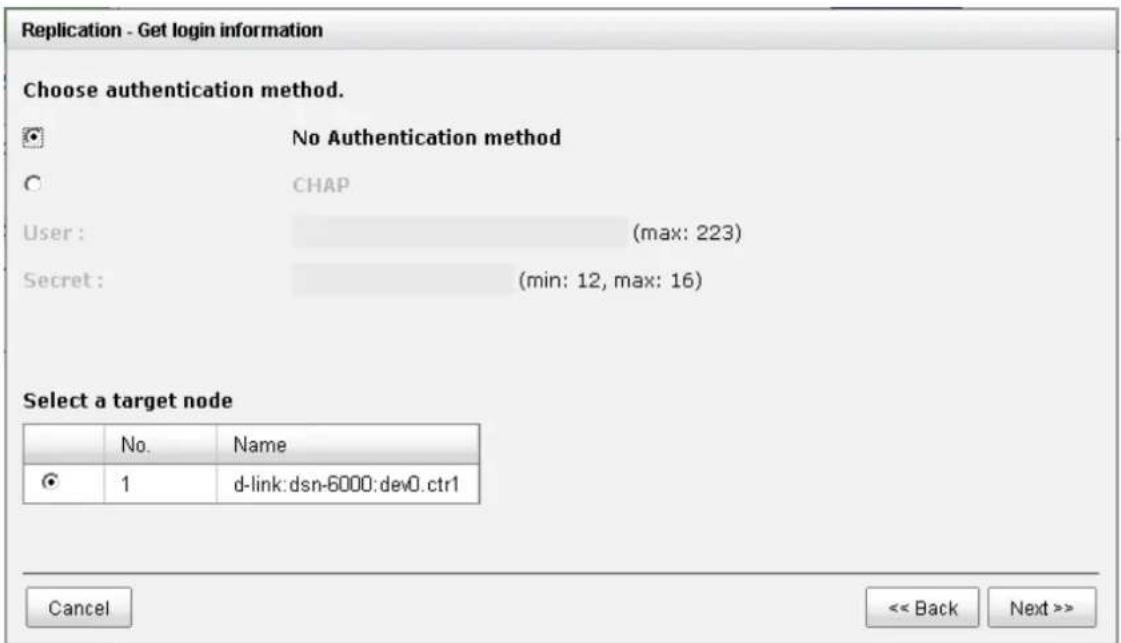
Figure 5.11.9
- Choose the backup VD and click "Next".

Figure 5.11.10
- A new replication job is created and listed on the Replication page.

Figure 5.11.11
- Run the replication job
- Click the "OP" button on the replication job to open operation menu. Click "Start" to run the replication job.
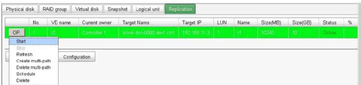
Figure 5.11.12
- Click "Start" again to confirm the execution of the replication job.
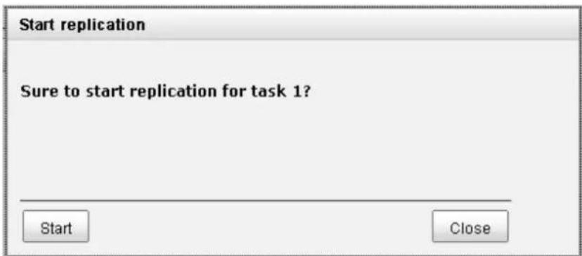
Figure 5.11.13
- User can monitor the replication job from the "Status" information and the progress is expressed by percentage.

Figure 5.11.14
- Create multi-path on the replication job
- Click the "Create multi-path" in the operation menu of the replication job.
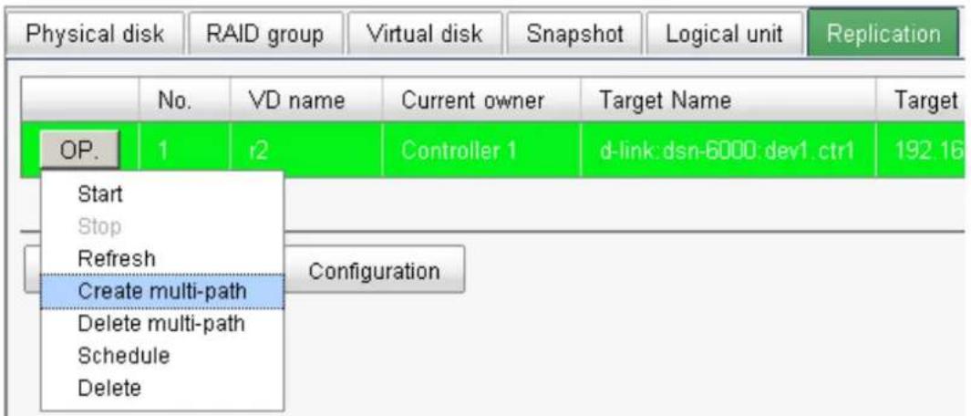
Figure 5.11.15
- Enter the IP of iSCSI port on controller 2 of the target IP SAN storage.
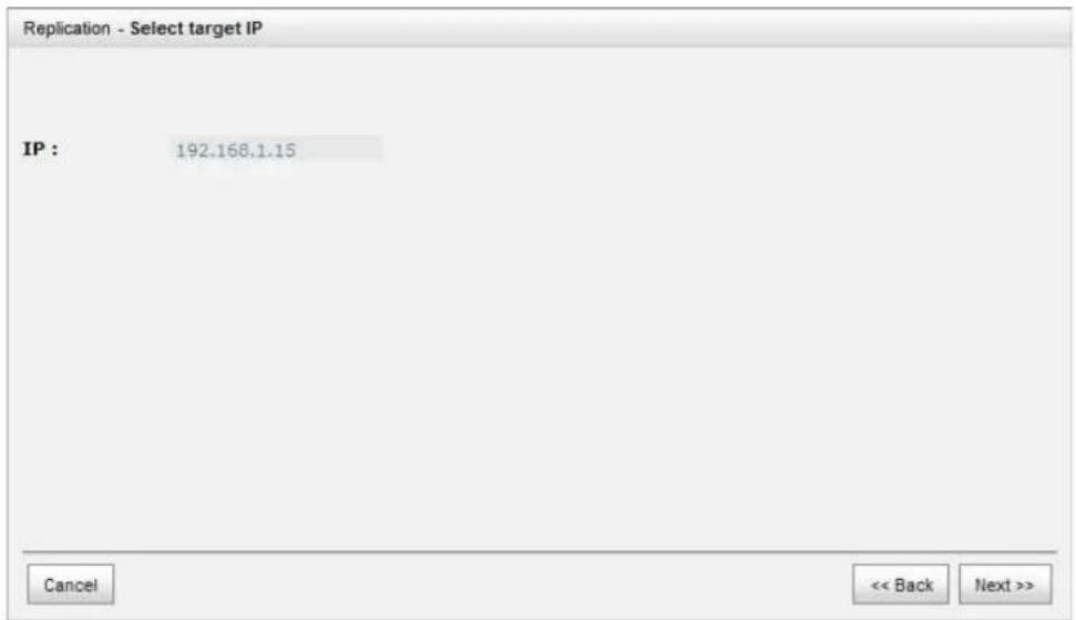
Figure 5.11.16
- Select the iSCSI node to log on and click "Next".

Figure 5.11.17
- Choose the same target VD and click "Next".

Figure 5.11.18
- A new target will be added in this replication job as a redundancy path.
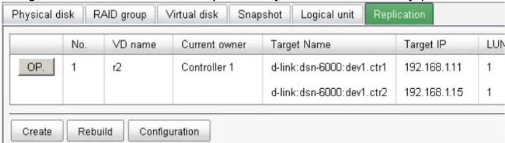
Figure 5.11.19
- Configure the replication job to run by schedule
- Click "Schedule" in the operation menu of the replication job.
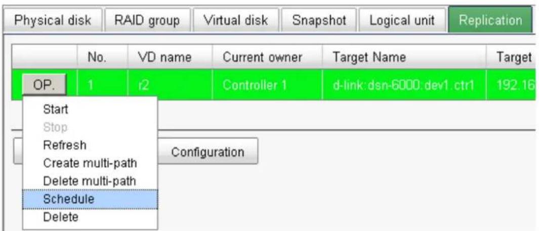
Figure 5.11.20
- The replication job can be scheduled to run by day, by week or by month. The execution time can be configurable per user's need.

Figure 5.11.21
- Configure the snapshot space
The Replication uses Snapshot technique of D-LINK, to help user to replicate the data without stop accessing to the source VD. If the snapshot space is not configured on the source VD in advance, the IP SAN storage will allocate snapshot space for the source VD automatically when the replication job is created. The default snapshot space allocated by the IP SAN storage is double size of the source VD. If the free space of the RG which the source VD resides in is less than double size of the source VD, the replication job will fail and pops up the error message.
To prevent this problem, user has to make sure the RG has enough free space for the snapshot space of source VD, or user has to configure the snapshot space of the source VD manually before the replication job is created.
- To configure the snapshot space settings of Replication, click the "configuration" button.

There are three settings in the Replication configuration menu,
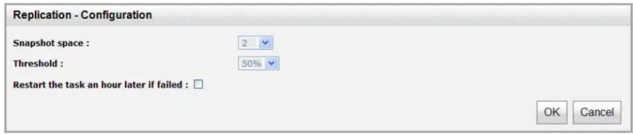
The Snapshot space specifies the ratio of snapshot space allocated to the source VD automatically when the snapshot space is not configured in advance. The default ratio is 2 to 1. It means when the replication job is creating, the IP SAN storage will automatically use the free space of RG to create a snapshot space which size is double of the source VD.
The Threshold setting will monitor the utilization of snapshot space. When the used snapshot space achieves the threshold, the IP SAN storage will automatically take a new snapshot and start the replication job. The purpose of threshold is to prevent the incremental copy fail immediately when running out of snapshot space. For example, the default threshold is 50%, and the system will check the snapshot space every hour. When the snapshot space is used over 50%, the IP SAN storage will automatically replicate data from the source VD to the target VD. Next time, when the rest snapshot space has been used over 50%, in other words, the total snapshot space has been used over 75%, the IP SAN storage will start the replication job again.
The Restart the task an hour later if failed setting is used when running out of snapshot space, the replication job will stop because there is no more available snapshot space. If this option has been check, the IP SAN storage will automatically clear the snapshots to release snapshot space, and the replication job will restart the task after an hour.

5.12 VLAN
VLAN (Virtual Local Area Network) is a logical grouping mechanism implemented on switch device using software rather than a hardware solution. VLANs are collections of switching ports that comprise a single broadcast domain. It allows network traffic to flow more efficiently within these logical subgroups. Please consult your network switch user manual for VLAN setting instructions. Most of the work is done at the switch part. All you need to do is to make sure that your iSCSI port's VLAN ID matches that of switch port.
• VLAN ID is a 12-bit number.
PCP(Priority Code Point) is a 3-bit number and reserved for QoS.
VLAN IDs range from 2 to 4094 with 0, 1, and 4095 reserved for special purposes (they are different from switches to switches.). Our PCP definition comply with IEEE 802.1p protocol, ranging from 0 to 7, with 0 as the default value. In normal cases, you don't need to set PCP value. Using the default setting will do just fine.
- Assign VLAN ID to iSCSI ports
- Go to "iSCSI Configuration", select "NIC" tab.
- Click on "OP" button of which port you prefer. Select "Set VLAN ID".
| Show information for: Controller 1 | |||||||
| Name | LAG | LAG No | VLAN ID | DHCP | IP address | Netmask | |
| OP. | LAN1 | No | N/A | N/A | No | 192.168.11.1 | 255.255.255.0 |
| OP. | LAN2 | No | N/A | N/A | No | 192.168.12.2 | 255.255.255.0 |
| Link aggregation or Multi-homed | |||||||
| Set VLAN ID | |||||||
| IP settings for iSCSI ports | |||||||
| Become default gateway | |||||||
| Enable jumbo frame | |||||||
| Ping host | |||||||
Figure 5.12.1
- Put in the same VLAN ID of the corresponding switch port that the iSCSI port is plugged in. And click "Ok".
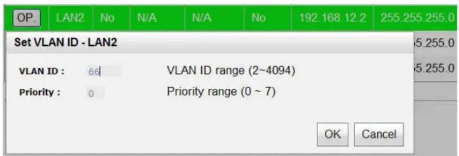
Figure 5.12.2
- VLAN ID 66 for LAN2 is set properly.
| NIC | Entity property | Node | Session | CHAP account | |||
| Show information for: Controller 1 | |||||||
| Name | LAG | LAG No | VLAN ID | DHCP | IP address | Netmask | |
| OP. | LAN1 | No | N/A | N/A | No | 192.168.11.1 | 255.255.255.0 |
| OP. | LAN2 | No | N/A | 66 | No | 192.168.12.2 | 255.255.255.0 |
| OP. | LAN3 | No | N/A | N/A | No | 192.168.11.3 | 255.255.255.0 |
| OP. | LAN4 | No | N/A | 10 | No | 192.168.12.4 | 255.255.255.0 |
| Aggregation | |||||||
Figure 5.12.3
- Assign VLAN ID to LAG(Trunking or LACP)
- After creating LAG, press "OP" button next to the LAG, and select "Set VLAN ID".
| Name | LAG | LAG No | VLAN ID | DHCP | IP address | |
| OP. | LAN1 | No | N/A | 11 | No | 192.168.11.5 |
| OP. | LAN2 | Trunking | 0 | N/A | No | 192.168.12.6 |
| OP. | LAN3 | Trunking | 0 | N/A | No | 192.168.12 6 |
| Delete link aggregation Link aggregation or Multi-homed | 12 | No | 192.168.12.8 | |||
| Set VLAN ID | ||||||
| IP settings for iSCSI ports Become default gateway Enable jumbo frame Ping host | ||||||
Figure 5.12.4
- Put in the VLAN ID and click ok. VLAN ID of LAG 0 is properly set.
| Name | LAG | LAG No | VLAN ID | DHCP | IP address | |
| OP. | LAN1 | No | N/A | 11 | No | 192.168.11.5 |
| OP. | LAN2 | Trunking | 0 | 100 | No | 192.168.12.6 |
| OP. | LAN3 | Trunking | 0 | 100 | No | 192.168.12.6 |
| OP. | LAN4 | No | N/A | 12 | No | 192.168.12.8 |
| Aggregation | ||||||
Figure 5.12.5
- If iSCSI ports are assigned with VLAN ID before creating aggregation takes place, aggregation will remove VLAN ID. You need to repeat step 1 and step 2 to set VLAN ID for the aggregation group.
- Assign VLAN ID to replication port
Please consult figure 5.11.3 of 5.11 Replication section for details.
- Always make sure correct VLAN IDs are assigned to the correct network ports (iSCSI, switch, and host NIC) to ensure valid connections.
Chapter 6 Troubleshooting
6.1 System buzzer
The system buzzer features are listed below:
- The system buzzer alarms 1 second when system boots up successfully.
- The system buzzer alarms continuously when there is error occurred. The alarm will be stopped after error resolved or be muted.
- The alarm will be muted automatically when the error is resolved. E.g., when RAID 5 is degraded and alarm rings immediately, user changes / adds one physical disk for rebuilding. When the rebuilding is done, the alarm will be muted automatically.
6.2 Event notifications
- PD events
| Level | Type | Description |
| INFO PD inserted Diskis inserted into system | ||
| WARNING PD removed Diskis removed from system | ||
| ERROR HDD read error Diskread block error | ||
| ERROR HDD write error Diskwrite block error | ||
| ERROR HDD error Diskis disabled | ||
| ERROR HDD IO timeout Diskgets no response | ||
| INFO PD upgrade started | PD [...] starts upgrading firmware process. | |
| INFO PD upgrade finished | PD [...] finished upgrading firmware process. | |
| WARNING PD upgrade failed | PD [...] upgrade firmware failed. | |
- HW events
| Level | Type | Description |
| WARNING | ECC single | Single-bit ECC error is detected at |
| ERROR | ECC multiple | Multi-bit ECC error is detected at |
| INFO ECC dimm | ECC memory is installed | |
| INFO ECC none | Non-ECC memory is installed | |
| INFO | SCSI bus reset | Received SCSI Bus Reset event at the SCSI Bus |
| ERROR SCSI host error SCSI Host allocation failed | ||
| ERROR SATA enable device fail | A enabled device fail | Failed to enable the SATA pci device |
| ERROR SATA EDMA mem fail | A EDMA mem fail | Failed to allocate memory for SATA EDMA |
| ERROR SATA remap mem fail | A remap mem fail | Failed to remap SATA memory io spcae |
| ERROR SATA PRD mem fail Failed to init SATA PRD memory manager | ||
| ERROR SATA revision id fail Failed to get SATA revision id | ||
| ERROR SATA set reg fail Failed to set SATA register | ||
| ERROR SATA init fail Core failed to initialize the SATA adapter | ||
| ERROR SATA diag fail SATA Adapter diagnostics failed | ||
| ERROR Mode ID fail SATA Mode ID failed | ||
| ERROR SATA chip count error | SATA Chip count error | |
| INFO SAS port reply error SAS HBA | A portreply terminated abnormally | |
| INFO SAS unknown port reply error | SAS frontend reply terminated abnormally | |
| INFO FC port reply error FC HBA | portreply terminated abnormally | |
| INFO FC unknown port reply error | FC frontend reply terminated abnormally | |
- EMS events
| Level | Type | Description |
| INFO Power install Power() is installed | ||
| ERROR Power absent Power() is absent | ||
| INFO Power restore Power() is restored to work. | ||
| ERROR Power fail Power() is not functioning | ||
| WARNING | Power detect | PSU signal detection() |
| INFO Fan restore Fan() is restored to work. | ||
| ERROR Fan fail Fan() is not functioning | ||
| INFO Fan install Fan() is installed | ||
| ERROR Fan not present Fan() is not present | ||
| ERROR Fan over speed Fan() is over speed | ||
| WARNING | Thermal level 1 | System temperature() is higher. |
| ERROR | Thermal level 2 | System Overheated()!!! |
| ERROR Thermal level 2 shutdown | System Overheated()!!! The system will auto-shutdown immediately. | |
| ERROR Thermal level 2 CTR shutdown | The controller will auto shutdown immediately, reason [ Overheated() ]. | |
| WARNING | Thermal ignore value | Unable to update thermal value on |
| WARNING | Voltage level 1 | System voltage() is higher/lower. |
| ERROR | Voltage level 2 | System voltages() failed!!! |
| ERROR Voltage level 2 shutdown | System voltages() failed!!! The system will auto-shutdown immediately. | |
| ERROR Voltage level 2 CTR shutdown | The controller will auto shutdown immediately, reason [ Voltage abnormal() ]. | |
| INFO UPS OK Successfully detect UPS | ||
| WARNING | UPS fail | Failed to detect UPS |
| ERROR UPS AC loss AC loss for system is detected | ||
| ERROR | UPS power low | UPS Power Low!!! The system will auto-shutdown immediately. |
| WARNING | SMART T.E.C. | DiskS.M.A.R.T. Threshold Exceed Condition occurred for attribute |
| WARNING | SMART fail | Disk: Failure to get S.M.A.R.T information |
| WARNING | RedBoot failover | RedBoot failover event occurred |
| WARNING | Watchdog shutdown | Watchdog timeout shutdown occurred |
| WARNING | Watchdog reset | Watchdog timeout reset occurred |
- RMS events
| Level | Type | Description |
| INFO | Console Login | <username> login from<IP or serial console> via Console UI |
| INFO | Console Logout | <username> logout from<IP or serial console> via Console UI |
| INFO Web Log | Login <username> login from<IP> via Web UI | |
| INFO Web Log | Logout <username> logout from<IP> via Web UI | |
| INFO Log clear All event logs are cleared | ||
| WARNING | Send mail fail Failed to send event to. | |
- Snapshot events
| Level | Type | Description |
| WARNING | Snap mem | Failed to allocate snapshot memory for VD. |
| WARNING | Snap space overflow | Failed to allocate snapshot space for VD. |
| WARNING | Snap threshold The snapshot space threshold of VDhas been reached. | |
| INFO | Snap delete | The snapshot VDhas been deleted. |
| INFO | Snap auto delete | The oldest snapshot VDhas been deleted to obtain extra snapshot space. |
| INFO | Snap take | A snapshot on VDhas been taken. |
| INFO | Snap set space | Set the snapshot space of VDto MB. |
| INFO Snap | rollback started | Snapshot rollback of VDhas been started. |
| INFO Snap | rollback finished | Snapshot rollback of VDhas been finished. |
| WARNING | Snap quota reached | The quota assigned to snapshotis reached. |
| INFO | Snap clear space | The snapshot space of VDis cleared |
- iSCSI events
| Level | Type | Description |
| INFO iSCSI | login accepted | iSCSI login fromsucceeds. |
| INFO | iSCSI login rejected | iSCSI login fromwas rejected, reason[] |
| INFO | iSCSI logout recvd | iSCSI logout fromwas received, reason[]. |
- Battery backup events
| Level | Type | Description |
| INFO | BBM start syncing | Abnormal shutdown detected, start flushing battery-backed data (<number> KB). |
| INFO | BBM stop syncing | Abnormal shutdown detected, flushing battery-backed data finished |
| INFO BBM installed Battery backup module is detected | ||
| INFO BBM status good Battery backup module is good | ||
| INFO BBM status charging | Battery backup module is charging | |
| WARNING | BBM status fail Battery backup module is failed | |
| INFO BBM enabled Battery backup feature is. | ||
| INFO BBM inserted Battery backup module is inserted | ||
| INFO BBM removed Battery backup module is removed | ||
- JBOD events
| Level | Type | Description |
| INFO | PD upgrade started | JBODPD[] starts upgrading firmware process. |
| INFO PD upgrade finished | grade finished | JBODPD[] finished upgrading firmware process. |
| WARNING | PD upgrade failed JBODPD[] upgrade firmware failed. | |
| INFO | PD freed | JBODPDhas been freed from RG. |
| INFO | PD inserted | JBODdiskis inserted into system. |
| Warning | PD removed | JBODdiskis removed from system. |
| ERROR | HDD read error | JBODdiskread block error |
| ERROR | HDD write error | JBODdiskwrite block error |
| ERROR | HDD error | JBODdiskis disabled. |
| ERROR | HDD IO timeout | JBODdiskgets no response |
| INFO | JBOD inserted | JBODis inserted into system |
| WARNING | JBOD removed | JBODis removed from system |
| WARNING | SMART T.E.C JBODdisk:S.M.A.R.T. Threshold Exceed Condition occurred for attribute | |
| WARNING | SMART fail | JBODdisk:Failure to get S.M.A.R.T information |
| INFO | PD dedicated spare | Assign JBODPDto be the dedicated spare disk of RG. |
| INFO | PD global spare | Assign JBODPDto Global Spare Disks. |
| ERROR | Config read fail | Config read error occurred at LBA--of JBODPD. |
| ERROR | Config write fail | Config write error occurred at LBA--of JBODPD. |
| WARNING | PD read error | Read error occurred at LBA--of JBODPD. |
| WARNING | PD write error | Write error occurred at LBA--of JBODPD. |
| INFO | PD scrub started | JBODPDstarts disk scrubbing process. |
| INFO | PD scrub completed | JBODPDcompleted disk scrubbing process. |
| WARNING | PS fail | Power Supply ofin JBODis FAIL |
| INFO | PS normal | Power Supply ofin JBODis NORMAL |
| WARNING | FAN fail | Cooling fan ofin JBODis FAIL |
| INFO | FAN normal | Cooling fan ofin JBODis NORMAL |
| WARNING | Volt warn OV | Voltage ofread asin JBODis WARN OVER |
| WARNING | Volt warn UV | Voltage ofread asin JBODis WARN UNDER |
| WARNING | Volt crit OV | Voltage ofread asin JBODis CRIT OVER |
| WARNING | Volt crit UV | Voltage ofread asin JBODis CRIT UNDER |
| INFO Volt recovery Voltage ofin JBODis NORMAL | ||
| WARNING | Therm warn OT | Temperature ofread asin JBODis OT WARNING |
| WARNING | Therm warn UT | Temperature ofread asin JBODis UT WARNING |
| WARNING | Therm fail OT | Temperature ofread asin JBODis OT FAILURE |
| WARNING | Therm fail UT | Temperature ofread asin JBODis UT FAILURE |
| INFO Therm recovery Temperature in JBODis NORMAL | ||
- System maintenance events
| Level | Type | Description |
| INFO System shutdown System shutdown. | ||
| INFO System reboot System reboot. | ||
| INFO System console shutdown | System shutdown fromvia Console UI | |
| INFO System web shutdown | System shutdown fromvia Web UI | |
| INFO System button shutdown | System shutdown via power button | |
| INFO System LCM shutdown | System shutdown via LCM | |
| INFO System console reboot | System reboot fromvia Console UI | |
| INFO System web reboot System reboot fromvia Web UI | ||
| INFO System LCM reboot System reboot via LCM | ||
| INFO FW upgrade start System firmware upgrade starts. | ||
| INFO FW upgrade success | System firmware upgrade succeeds. | |
| WARNING | FW upgrade failure | System firmware upgrade is failed. |
| ERROR | IPC FW upgrade timeout | System firmware upgrade timeout on another controller |
| INFO Config importedconfig imported | ||
- HAC events
| Level | Type | Description |
| INFO | RG owner changed | The preferred owner of RGhas been changed to controller. |
| INFO Force | CTR write through | Controllerforced to adopt write-through mode on failover. |
| INFO Restore | CTR cache mode | Controllerrestored to previous caching mode on failback. |
| INFO | Failover complete | All volumes in controllercompleted failover process. |
| INFO | Failback complete | All volumes in controllercompleted failback process. |
| INFO | CTR inserted | Controlleris inserted into system |
| ERROR | CTR removed | Controlleris removed from system |
| ERROR | CTR timeout | Controllergets no response |
| ERROR | CTR lockdown | Controlleris locked down |
| ERROR CTR | memory NG Memory size mismatch | |
| ERROR CTR | firmware NG Firmware version mismatch | |
| ERROR CTR | lowspeed NG Low speed inter link is down | |
| ERROR CTR | highspeed NG High speed inter link is down | |
| ERROR CTR | backend NG SAS expander is down | |
| ERROR CTR | frontend NG FC IO controller is down | |
| INFO CTR | reboot FW sync | Controller reboot, reason [Firmware synchronization completed] |
- Clone events
| Level | Type | Description |
| INFO VD clone started VDstarts cloning process. | ||
| INFO VD clone finished VDfinished cloning process. | ||
| WARNING VD clone failed The cloning in VDfailed. | ||
| INFO | VD clone aborted | The cloning in VDwas aborted. |
| INFO | VD clone set | The clone of VDhas been designated. |
| INFO | VD clone reset | The clone of VDis no longer designated. |
| WARNING | Auto clone error Auto clone task:. | |
| WARNING | Auto clone no snap | Auto clone task: Snapshotis not found for VD. |
- Replication events
| Level | Type | Description |
| INFO Replication portal enabled | LANis enabled for Replication portal | |
| INFO Replication portal disabled | Replication portal is disabled | |
| INFO | VD replicate started | VDstarts replication process. |
| INFO VD replicate finished | VDfinished replication process. | |
| WARNING | VD replicate failed | The replication in VDfailed. |
| INFO VD replicate aborted | The replication in VDwas aborted. | |
| INFO | VD set as replica | VDhas been configured as a replica. |
| INFO | VD set as RAID | VDhas been configured as a RAID volume. |
| INFO | VD replica set | The replica of VDhas been designated. |
| INFO | VD replica reset | The replica of VDis no longer designated. |
| WARNING | Auto grep not enable | Auto Replication task: Replication is not enabled for VD. |
| WARNING | Auto grep error | Auto Replication task:. |
| WARNING | Auto grep no snap | Auto Replication task: Snapshotis not found for VD. |
| INFO Source replicate started | Remote VDstarts replicating to VD. | |
| INFO Source replicate finished | Remote VDfinished replication to VD. | |
| INFO Source replicate failed | Remote VDfailed replication to VD. | |
| INFO Source replicate aborted | Remote VDaborted replication to VD. | |
Appendix
A. Certification list
• iSCSI Initiator (Software)
| OS | Software/ Release | Number |
| Microsoft Windows | Microsoft iSCSI Software Initiator Release v2.08System Requirements:1. Windows 2000 Server with SP42. Windows Server 2003 with SP23. Windows Server 2008 with SP2 | |
| Linux | The iSCSI Initiators are different for different Linux Kernels.1. For Red Hat Enterprise Linux 3 (Kernel 2.4), install linux-iscsi-3.6.3.tar2. For Red Hat Enterprise Linux 4 (Kernel 2.6), use the build-in iSCSI initiator iscsi-initiator-utils-4.0.3.0-4 in kernel 2.6.93. For Red Hat Enterprise Linux 5 (Kernel 2.6), use the build-in iSCSI initiator iscsi-initiator-utils-6.2.0.742-0.5.el5 in kernel 2.6.18 | |
| Mac | ATTO Xtend SAN iSCSI initiator v3.10System Requirements:1. Mac OS X v10.5 or later |
For ATTO Xtend SAN iSCSI initiator, it is not free. Please contact your local distributor.
• GbE iSCSI HBA card
| Vendor | Model |
| HP NC380T (PCI-Express, Gigabit, 2 ports, TCP/IP offload, iSCSI offload) | |
| QLogic QLA4010C (PCI-X, Gigabit, 1 port, TCP/IP offload, iSCSI offload) | |
| QLogic QLA4052C (PCI-X, Gigabit, 2 ports, TCP/IP offload, iSCSI offload) | |
| QLogic QLE4062C (PCI-Express, Gigabit, 2 ports, TCP/IP offload, iSCSI offload) | |
• GbE NIC
| Vendor | Model |
| HP NC7170 (PCI-X, Gigabit, 2 ports) | |
| HP NC360T (PCI-Express, Gigabit, 2 ports, TCP/IP offload) | |
| IBM NetXtreme 1000 T (73P4201) (PCI-X, Gigabit, 2 ports, TCP/IP offload) | |
| Intel PWLA8492MT (PCI-X, Gigabit, 2 ports, TCP/IP offload) | |
- GbE Switch
| Vendor | Model |
| D-Link All of D-Link Managed Gigabit Switch | |
| Dell | PowerConnect 5324 |
| Dell | PowerConnect | 2724 |
| Dell | PowerConnect | 2708 |
| HP | ProCurve | 1800-24G |
| Netgear | GS724T | |
| ZyXEL | GS2200 |
- Hard drive
SAS drives are recommended on dual controller system. For SATA drives, SATA bridge boards are required in dual controller configuraiton.
SAS 3.5"
| Vendor | Model |
| Hitachi Ultrastar | 15K147, HUS151436VLS300, 36GB, 15000RPM, SAS 3.0Gb/s, 16M |
| Hitachi Ultrastar | 15K300, HUS153073VLS300, 73GB, 15000RPM, SAS 3.0Gb/s, 16M (F/W: A410) |
| Seagate Cheetah | 15K.4, ST336754SS, 36.7GB, 15000RPM, SAS 3.0Gb/s, 8M |
| Seagate Cheetah | 15K.5, ST373455SS, 73.4GB, 15000RPM, SAS 3.0Gb/s, 16M |
| Seagate Cheetah | 15K.5, ST3146855SS, 146.8GB, 15000RPM, SAS 3.0Gb/s, 16M |
| Seagate Cheetah | 15K.6, ST3450856SS, 450GB, 15000RPM, SAS 3.0Gb/s, 16M (F/W: 003) |
| Seagate Cheetah | NS, ST3400755SS, 400GB, 10000RPM, SAS 3.0Gb/s, 16M |
| Seagate Barracuda | ES.2, ST31000640SS, 1TB, 7200RPM, SAS 3.0Gb/s, 16M (F/W: 0002) |
| Seagate Cheetah | NS.2, ST3600002SS, 600GB, 10000RPM, SAS 2.0, 6.0Gb/s, 16M (F/W: 0004) |
| Seagate Cheetah | 15K.7, ST3600057SS, 600GB, 15000RPM, SAS 2.0, 6.0Gb/s, 16MB (F/W: 0004) |
| Seagate | Constellation ES, ST31000424SS, 1TB, 7200RPM, SAS 2.0 6.0Gb/s, 16MB (F/W: 0005) |
| Seagate Constellation ES, ST32000444SS, 2TB, 7200RPM, SAS 2.0 6.0Gb/s, 16MB (F/W: 0005) | |
SAS 2.5"
| Vendor | Model |
| Seagate Savvio 1 | 0K.3, ST9300603SS, 300GB, 10000RPM, SAS 2.0, 6.0Gb/s, 16M (F/W: 0003) |
| Seagate Savvio 1 | 5K.2, ST9146852SS, 147GB, 15000RPM, SAS 2.0, 6.0Gb/s, 16M (F/W: 0002) |
| Seagate | Constellation, ST9500430SS, 500GB, 7200RPM, SAS 2.0, 6.0Gb/s, 16M (F/W: 0001) |
SATA 3.5"
| Vendor | Model |
| Hitachi Deskstar | 7K250, HDS722580VLSA80, 80GB, 7200RPM, SATA, 8M |
| Hitachi | Deskstar E7K500, HDS725050KLA360, 500GB, 7200RPM, SATA II, 16M |
| Hitachi Deskstar | 7K80, HDS728040PLA320, 40GB, 7200RPM, SATA II, 2M |
| Hitachi | Deskstar T7K500, HDT725032VLA360, 320GB, 7200RPM, SATA II, 16M |
| Hitachi Deskstar | P7K500, HDP725050GLA360, 500GB, 7200RPM, SATA II, 16M (F/W:K2A0AD1A) |
| Hitachi Deskstar | E7K1000, HDE721010SLA330, 1TB, 7200RPM, SATA 3.0Gb/s, 32MB, NCQ (F/W: ST60A3AA) |
| Hitachi | UltraStar A7K2000, HUA722020ALA330, 2TB, 7200RPM, SATA NCQ (F/W: JKAOA20N) |
| Maxtor DiamondMax Plus 9, 6Y080M0, 80GB, 7200RPM, SATA, 8M | |
| Maxtor | DiamondMax 11, 6H500F0, 500GB, 7200RPM, SATA 3.0Gb/s, 1 |
| Samsung | SpinPoint P80, HDSASP0812C, 80GB, 7200RPM, SATA, 8M |
| Seagate Barracuda | 7200.7, ST380013AS, 80GB, 7200RPM, SATA 1.5Gb/s, 8M |
| Seagate Barracuda | 7200.7, ST380817AS, 80GB, 7200RPM, SATA 1.5Gb/s, 8M, NCQ |
| Seagate Barracuda | 7200.8, ST3400832AS, 400GB, 7200RPM, SATA 1.5Gb/s, 8M, NCQ |
| Seagate Barracuda | 7200.9, ST3500641AS, 500GB, 7200RPM, SATA 3.0Gb/s, 16M, NCQ |
| Seagate Barracuda | 7200.11, ST3500320AS, 500GB, 7200RPM, SATA 3.0Gb/s, 32M, NCQ |
| Seagate Barracuda | 7200.11, ST31000340AS, 1TB, 7200RPM, SATA 3.0Gb/s, 32M, NCQ |
| Seagate Barracuda | 7200.11, ST31500341AS, 1.5TB, 7200RPM, SATA 3.0Gb/s, 32M, NCQ (F/W: SD17) |
| Seagate NL35.2, | ST3400633NS, 400GB, 7200RPM, SATA 3.0Gb/s, 16M |
| Seagate NL35.2, | ST3500641NS, 500GB, 7200RPM, SATA 3.0Gb/s, 16M |
| Seagate Barracuda | ES, ST3500630NS, 500GB, 7200RPM, SATA 3.0Gb/s, 16M |
| Seagate Barracuda | ES, ST3750640NS, 750GB, 7200RPM, SATA 3.0Gb/s, 16M |
| Seagate Barracuda | ES.2, ST31000340NS, 1TB, 7200RPM, SATA 3.0Gb/s, 32M (F/W: SN06) |
| Seagate SV35.5, | ST3500410SV, 500GB, 7200 RPM, SATA 3.0Gb/s, 16M, NCQ (F/W: CV11) |
| Seagate Constellation ES, ST31000524NS, 1TB, 7200RPM, SATA 3.0Gb/s, 32M, NCQ (F/W: SN11) | |
| Westem Digital Caviar SE, WD800JD, 80GB, 7200RPM, SATA 3.0Gb/s, 8M | |
| Westem Digital Caviar SE, WD1600JD, 160GB, 7200RPM, SATA 1.5G/s, 8M | |
| Westem Digital Caviar RE2, WD4000YR, 400GB, 7200RPM, SATA 1.5Gb/s, 16M, NCQ | |
| Westem Digital Caviar RE16, WD5000AAKS, 500GB, 7200RPM, SATA 3.0Gb/s, 16M | |
| Westem Digital RE2, WD4000YS, 400GB, 7200RPM, SATA 3.0Gb/s, 16M | |
| Westem Digital RE2, WD5000ABYS, 500GB, 7200RPM, SATA 3.0Gb/s, 16M, NCQ | |
| Westem Digital RE2-GP, WD1000FYPS, 1TB, 7200RPM, SATA 3.0Gb/s, 16M | |
| Westem Digital RE3, WD1002FBYS, 1000GB, 7200RPM, SATA 3.0Gb/s, 32M, NCQ (F/W: 03.00C05) | |
| Westem Digital RE4, WD2002FYPS, 2TB, IntelliPower, SATA 3.0Gb/s, 64M, NCQ (F/W: 04.05G04) | |
| Westem Digital RE4-GP, WD2002FYPS, 2TB, IntelliPower, SATA 3.0Gb/s, 64M, NCQ (F/W: 04.01G01) | |
| Westem Digital RE4, WD2003FYYS, 2TB, 7200RPM, SATA 3.0Gb/s, 64M, NCQ (F/W: 01.01D01) | |
| Westem Digital RE4, WD1003FBYX, 1TB, 7200RPM, SATA 3.0Gb/s, 64M, NCQ (F/W: 01.01V01) | |
| Westem Digital RE4, WD5003ABYX, 500GB, 7200RPM, SATA 3.0Gb/s, 64M, NCQ (F/W: 01.01S01) | |
| Westem Digital Raptor, WD360GD, 36.7GB, 10000RPM, SATA 1.5Gb/s, 8M | |
| Westem Digital VelcoiRaptor, WD3000HLFS, 300GB, 10000RPM, SATA 3.0Gb/s, 16M (F/W: 04.04V01) | |
SATA 2.5"
| Vendor | Model |
| Seagate | Constellation, ST9500530NS, 500GB, 7200RPM, SATA 3.0Gb/s, 32M (F/W: SN02) |
B. Microsoft iSCSI initiator
Here is the step by step to setup Microsoft iSCSI Initiator. Please visit Microsoft website for latest iSCSI initiator. This example is based on Microsoft Windows Server 2008 R2.
- Connect
- Run Microsoft iSCSI Initiator.
- Input IP address or DNS name of the target. And then click "Quick Connect".
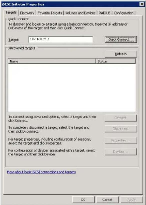
Figure B.1
- Click "Done".

Figure B.2
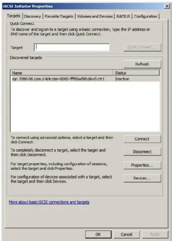
Figure B.3
- It can connect to an iSCSI disk now.
- MPIO
- If running MPIO, please continue.
- Click "Discovery" tab to connect the second path.
- Click "Discover Portal". Input IP address or DNS name of the target.

Figure B.4
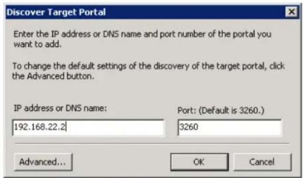
Figure B.5
8. Click "OK".

Figure B.6

Figure B.7
- Click "Targets" tab, select the second path, and then click "Connect".
- Enable "Enable multi-path" checkbox. Then click "OK".
- Done, it can connect to an iSCSI disk with MPIO.
- MC/S
- If running MC/S, please continue.
- Select one target name, click "Properties...".
- Click "MCS..." to add additional connections.

Figure B.8
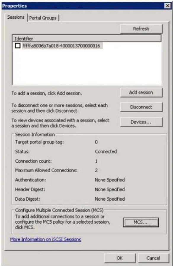
Figure B.9
- Click "Add...".
- Click "Advanced...".

Figure B.10

Figure B.11
- Select Initiator IP and Target portal IP, and then click "OK".
- Click "Connect".
- Click "OK".

Figure B.12

Figure B.13
- Done.
- Disconnect
- Select the target name, click "Disconnect", and then click "Yes".
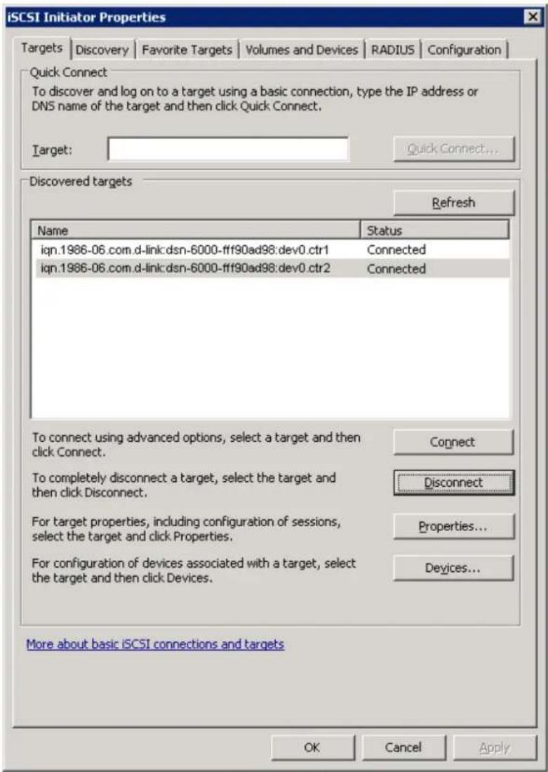
Figure B.14
- Done, the iSCSI device disconnect successfully.
C. From single controller to dual controllers
This SOP applies to upgrading from DSN-6110 to DSN-6120 as well as from DSN-6410 to DSN-6420. Before you do this, please make sure that either DSN-6110 or DSN-6410 is properly installed according to the manuals, especially the HDD trays. If you are NOT using SAS hard drives, you need to use HDD trays with either multiplexer board or bridge board to install your HDDs in order to utilize the dual controller mode features. Otherwise, the IP SAN system will not be able to recognize the HDDs.
Before you can insert the second controller to the IP SAN storage, the IP SAN storage system should be up and running and looks like the following screenshot in "Maintenance\System". Note that the status is single and you have one controller only.

You can also verify controller mode in "Maintenance\Upgrade". Check out the "Controller Mode" section.
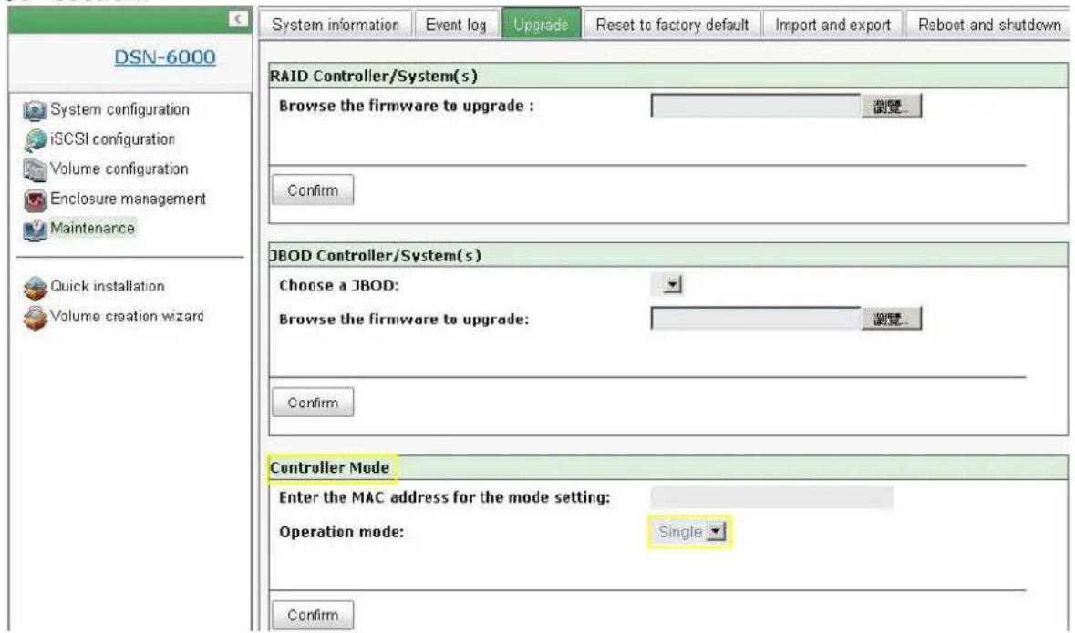
Please follow the steps below to upgrade to dual controller mode.
Step 1
Go to "Maintenance\System". Copy the IP SAN storage serial number.

Step 2
Go to "Maintenance\Upgrade" and paste the serial number into "Controller Mode" section. Select "Dual" as operation mode.
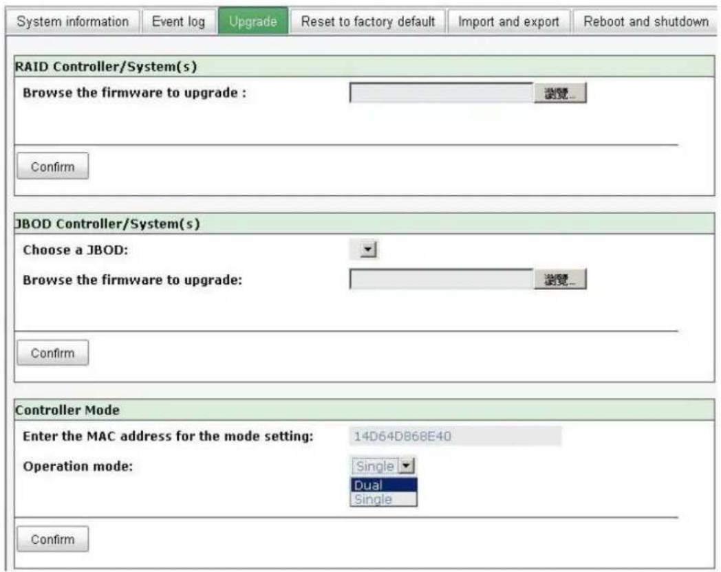
Step 3
Click "confirm". The system will ask you to shutdown. Please shutdown IP SAN storage.
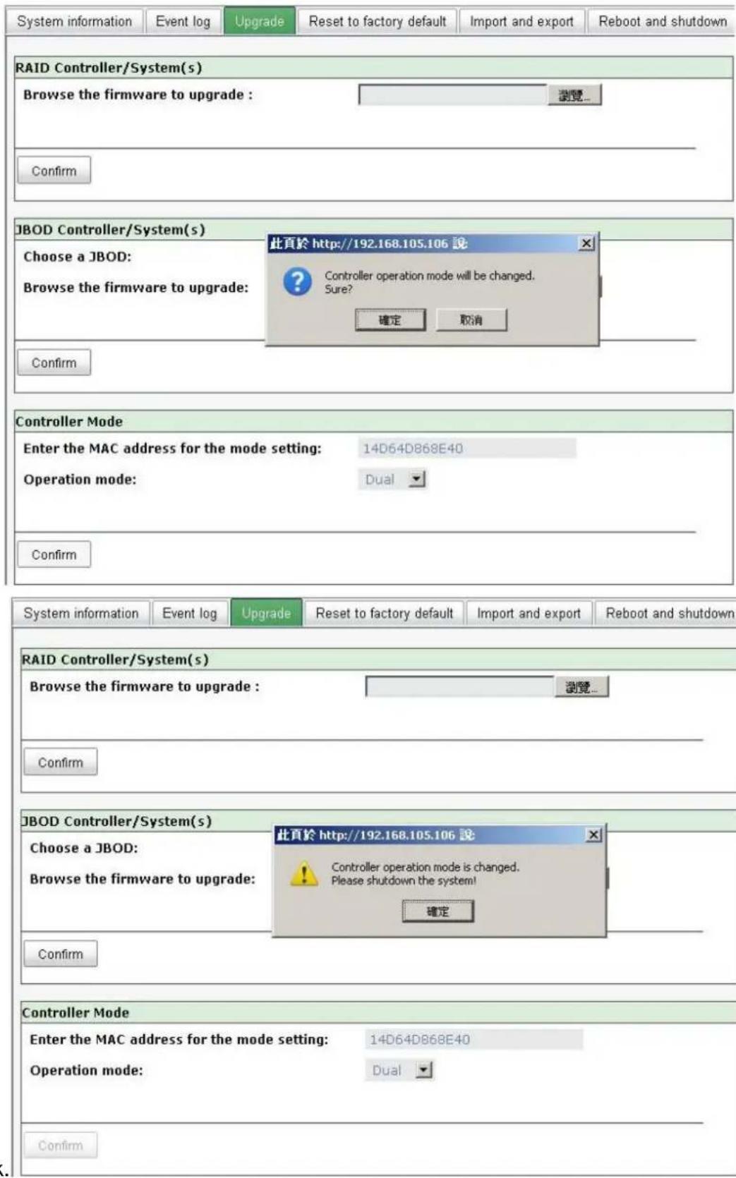
Click Ok.
Go to "Maintenance\Reboot and shutdown". Click "Shutdown" to shutdown the system.
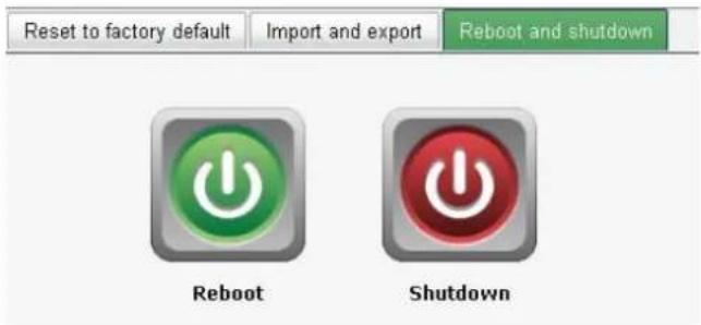
Click Ok.

Step 4
Power off DSN-6110 or DSN-6410. Insert the second controller to the IP SAN storage. And then power on the system. The IP SAN storage should now become in dual controller mode as either DSN-6120 or DSN-6420.
You may go to "Maintenance\System information" to check out. The IP SAN storage is running in dual controller mode now.
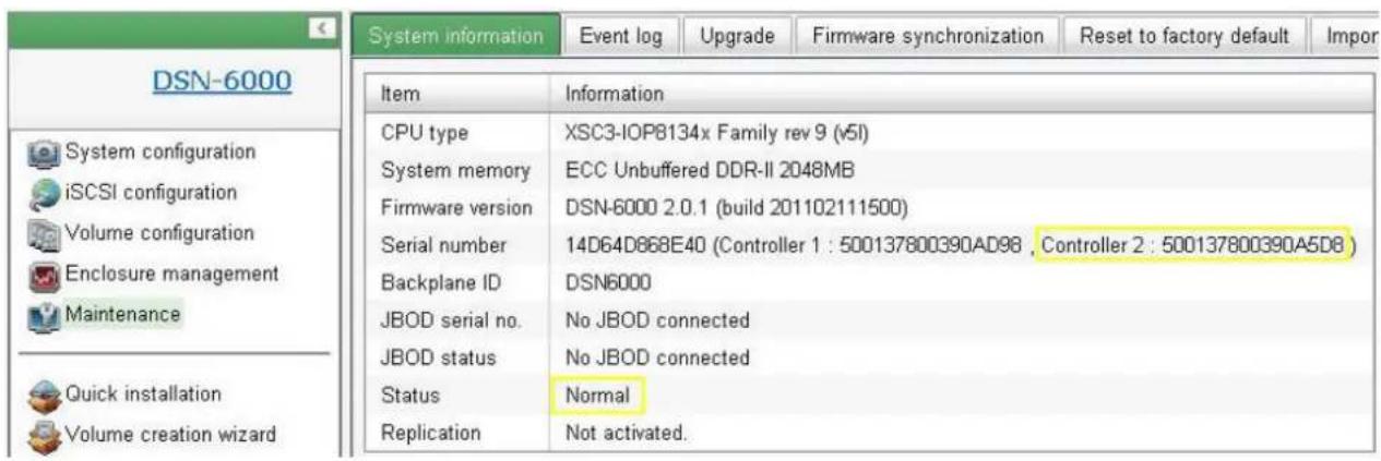


- D-Link iSCSI IP SAN storage
- User Manual
- Preface
- Copyright
- Trademarks
- About this manual
- Model comparison
- Caution
- Table of Contents
- Chapter 1 Overview 6
- Chapter 2 Installation....18
- Chapter 3 Quick setup.... 27
- Chapter 4 Configuration 35
- Enclosure management 69
- System maintenance....74
- Home/Logout/Mute....79
- Chapter 5 Advanced operations....80
- Chapter 6 Troubleshooting 117
- Chapter 1 Overview
- Features
- Highlights
- RAID concepts
- Terminology
- RAID levels
- Volume relationship
- iSCSI concepts
- IP SAN storage specifications
- Technical specifications
- - Controller features
- - System key components
- • RAID and volume operation
- • Advanced data protection
- • Enclosure monitoring
- - Management interface
- - iSCSI features
- - Host connection
- - OS support
- - Drive support
- • Power and Environment
- - Dimensions
- FCC and CE statements
- FCC statement
- CE statement
- UL statement
- Chapter 2 Installation
- Package contents
- Before installation
- Enclosure
- Front view
- Tips
- Front LED lights
- Install drives
- Rear view
- Install battery backup module
- Deployment
- Chapter 3 Quick setup
- Management interfaces
- Serial console
- Remote control
- Web UI
- How to use the system quickly
- Quick installation
- Volume creation wizard
- Chapter 4 Configuration
- Web UI management interface hierarchy
- System configuration
- iSCSI configuration
- Volume configuration
- Enclosure management
- Maintenance
- System configuration
- System setting
- Network setting
- Login setting
- Mail setting
- Notification setting
- iSCSI configuration
- NIC
- - IP settings:
- - Default gateway:
- - MTU / Jumbo frame:
- • Multi-homed / Trunking / LACP:
- - Ping host:
- Entity property
- Node
- - CHAP:
- - Change portal:
- - Rename alias:
- Session
- CHAP account
- Click "OK".
- Volume configuration
- Physical disk
- RAID group
- Virtual disk
- Snapshot
- - Snapshot operation description:
- Logical unit
- Example
- - Example
- Step 2: Create VD (Virtual Disk).
- Step 3: Attach a LUN to a VD.
- Enclosure management
- Hardware monitor
- UPS
- SES
- Hard drive S.M.A.R.T.
- System maintenance
- System information
- Event log
- Upgrade
- Firmware synchronization
- Reset to factory default
- Import and export
- Reboot and shutdown
- Home/ Logout/ Mute
- Home
- Logout
- Mute
- Chapter 5 Advanced operations
- Volume rebuild
- RG migration
- VD extension
- Snapshot
- Create snapshot volume
- Auto snapshot
- Rollback
- Snapshot constraint
- - Create a data-consistent snapshot
- • What if the snapshot space is over?
- • How many snapshots can be created on a VD
- - Rollback / Delete snapshot
- Disk roaming
- VD clone
- - Start VD clone
- SAS JBOD expansion
- Connecting JBOD
- Upgrade firmware of JBOD
- MPIO and MC/ S
- Difference:
- Trunking and LACP
- Dual controllers (only for DSN-6120)
- Perform I/O
- Ownership
- Controller status
- Replication
- - Setup the Replication port on the source IP SAN storage
- - Create backup VD on the target IP SAN storage
- - Create replication job on the source IP SAN storage
- - Run the replication job
- - Create multi-path on the replication job
- - Configure the snapshot space
- VLAN
- - Assign VLAN ID to LAG(Trunking or LACP)
- Chapter 6 Troubleshooting
- System buzzer
- Event notifications
- - Clone events
- - Replication events
- Appendix
- Certification list
- • iSCSI Initiator (Software)
- • GbE iSCSI HBA card
- • GbE NIC
- - GbE Switch
- - Hard drive
- Microsoft iSCSI initiator
- - Connect
- - MPIO
- Click "OK".
- - MC/S
- - Disconnect
- From single controller to dual controllers
- Step 1
- Step 2
- Step 3
- Step 4
Brand : D-LINK
Model : DSN-6120
Category : Server