
DNR-322L - Server D-LINK - Free user manual and instructions
Find the device manual for free DNR-322L D-LINK in PDF.


| Product Type | Network Video Recorder (NVR) |
| Brand | D-Link |
| Model | DNR-322L |
| Form Factor | Desktop / Rack-mountable |
| Number of HDD Bays | 4 (supports SATA II/III) |
| Maximum Storage Capacity | Up to 32 TB (4 x 8 TB) |
| Network Interface | Gigabit Ethernet (10/100/1000) |
| Video Recording Resolution | Up to 4K (3840x2160) at 30 fps |
| IP Camera Support | Up to 16 channels (license-free) |
| Compression Formats | H.265, H.264, MJPEG |
| RAID Support | RAID 0, 1, 5, 6, 10 (JBOD) |
| Power Supply | External, 100-240 VAC, 50/60 Hz |
| Power Consumption | Typical 35 W (without HDDs) |
| Dimensions (W x D x H) | 260 x 200 x 180 mm (10.2 x 7.9 x 7.1 in) |
| Weight | Approximately 3.5 kg (7.7 lbs) without HDDs |
| Operating Temperature | 0°C to 40°C (32°F to 104°F) |
| Humidity | 10% to 80% non-condensing |
| Cooling | 1 x 80mm fan (variable speed) |
| Management Interface | Web-based (HTTP/HTTPS), mobile app |
| Supported Protocols | IPv4, IPv6, TCP/IP, UDP, HTTP, HTTPS, NTP, DHCP, SMTP |
| Security | Password protection, IP filtering, HTTPS encryption |
| Maintenance | Regular firmware updates, HDD health monitoring |
| Spare Parts & Repairability | Replaceable HDDs, fan, power adapter; user serviceable |
Frequently Asked Questions - DNR-322L D-LINK
User questions about DNR-322L D-LINK
0 question about this device. Answer the ones you know or ask your own.
Ask a new question about this device
Download the instructions for your Server in PDF format for free! Find your manual DNR-322L - D-LINK and take your electronic device back in hand. On this page are published all the documents necessary for the use of your device. DNR-322L by D-LINK.
USER MANUAL DNR-322L D-LINK
natural_image
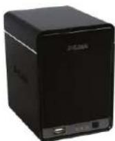
Front view of a black D-Link computer tower with ports and indicator lights (no readable text or symbols beyond branding)User Manual
2-Bay Professional Network Video Recorder (NVR)
DNR-322L
Manual Overview
D-Link reserves the right to revise this publication and to make changes in the content hereof without obligation to notify any person or organization of such revisions or changes. Information in this document may become obsolete as our services and websites develop and change. Please refer to the www.mydlink.com website for the most current information.
Manual Revisions
| Revision Date | Description | |
| 1.00 August | 02, 2011 DNR-322L A1 with firmware version 1.00 | |
| 1.10 December | 29, 2011 DNR-322L A1 with firmware version 1.10 | |
| 1.20 March | 05, 2012 DNR-322L A1 with firmware version 1.20 | |
| 1.21 April 13 | 2012 DNR-322L A1 with firmware version 1.20 | |
| 1.22 June 19 | 2012 DNR-322L A2 with firmware version 1.20 | |
| 1.30 May 7 | 2013 DNR-322L A2 with firmware version 1.30 | |
| 2.00 | November 26, 2013 | DNR-322L A2 with firmware version 2.00 |
| 2.10 | September 03, 2014 | add Erp Statement |
Trademarks
D-Link and the D-Link logo are trademarks or registered trademarks of D-Link Corporation or its subsidiaries in the United States or other countries. All other company or product names mentioned herein are trademarks or registered trademarks of their respective companies. Copyright © 2014 by D-Link Corporation.
All rights reserved. This publication may not be reproduced, in whole or in part, without prior expressed written permission from D-Link Corporation.
Power Usage
This device is an Energy Related Product (ErP) designed to be always on. It can be turned off through a power switch to save energy when it is not needed.
Switched Off: 0.36 watts
Table of Contents
Manual Overview ......i
Manual Revisions....i
Trademarks ...... i
Product Overview....1
Package Contents....1
System Requirements....2
Introduction 3
Features......4
Hardware Overview....7
Front View....7
Rear Panel (Connections)......8
Getting Started 9
NVR Software CD 9
Installation....10
Setup Wizard 10
Windows 10
Install the Hard Drives....11
Power and Device Selection....13
Admin password....14
HDD Configuration and Drive Mapping....15
Search for Cameras 16
Management Options....18
Set up Internet connection....19
Setup Wizard 21
Mac 21
Install the Hard Drives....23
Power and Device Selection 25
Admin password 26
HDD Configuration 27
Search for Cameras 28
Management Options....30
Set up Internet connection....31
mydlink Portal 33
NVR Status....34
Live Video 35
Playback....36
Status 37
NVR Info 38
Configuration 39
D-Link NVR Search Utility 39
Windows 39
D-Link NVR Search Utility 41
Mac 41
Web UI Login 43
Configure Hard Drive....44
Auto Search Camera 45
Web UI 47
Configuring the NVR....48
Network Setup....49
Table of Contents
| Camera Search......50 | Recorded Video Enhancement......89 |
| Camera Setup......51 | Save Video......90 |
| Audio and Video......52 | Save Image......91 |
| 2nd Stream Settings......53 | Print Image......92 |
| Live and Playback Setup......54 | Page Setting......92 |
| Recording Schedule......55 | Back up the Recorded Video......93 |
| Auto Backup......58 | Playback Manager Application......94 |
| Event Setup......59 | Set Connections to the Units......95 |
| E-mail Setup......61 | Backup System......96 |
| Time and Date Setup......62 | |
| Maintenance......63 | Verification Tool......98 |
| User Management......63 | Verify Image/Video......99 |
| System......65 | Troubleshooting......100 |
| RAID......66 | Choose a RAID Level......102 |
| Dynamic DNS......68 | Replacing or Adding a New Hard Drive......103 |
| Firmware Update......69 | |
| Status......70 | Technical Specifications......104 |
| Camera Status......70 | |
| System Info......71 | |
| System Log......72 | |
| NVR Log......73 | |
| Support......74 | |
| Live Video......75 | |
| General Setting......78 | |
| Multiple view......81 | |
| Playback......82 | |
| Open Record and Setting......85 | |
| Search the Recorded Video to Playback......87 |
Package Contents
• D-Link DNR-322L mydlink Network Video Recorder (NVR)
• CAT5 Ethernet Cable
- Power Adapter
- Cable Holder
- Keys
- Manual and Software on CD
- Quick Install Guide
Note: Using a power supply with a different voltage than the one included with your product will cause damage and void the warranty for this product.
If any of the above items are missing, please contact your reseller.
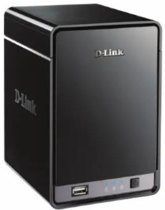
natural_image
Exterior view of a black D-Link mobile device with ports and indicator lights (no readable text or symbols beyond branding)System Requirements
| Hardware Requirements • One or two 3.5” SATA hard disk drive(s)* | |
| Network Requirements | Broadband Internet connection (for remote access)Network camera(s) (refer to the D-Link website for a list of supported cameras)10/100/1000 Mbit Gigabit Ethernet switch or router |
| Web-based Configuration Utility Requirements/Remote PC Minimum Requirements | Computer with the following:Microsoft Windows® 8, 7, Vista®, or XP (32-bit)Pentium 4 - 2.4 GHz or higher512 MB or higherBrowser Requirements:Windows Users: Internet Explorer or ChromeMac Users: SafariMake sure you have the latest version of Java installed. Visit www.java.com to download the latest version. |
| Optional UPS with USB interface | |
*Hard disk drives should be from the same manufacturer. To ensure maximum performance, identical drives are recommended for RAID 1 configurations.
Introduction
Congratulations on your purchase of the DNR-322L 2-bay mydlink NVR.
The DNR-322L is a standalone wired Network Video Recorder (NVR) which supports multi-channel network cameras with M-JPEG, MPEG4 or H.264 recording with 2 high-speed 3.5-inch SATA hard disks for long-term recording. Thanks to the powerful embedded system, the NVR can record video from network cameras located in local or remote sites to a dedicated HDD storage without requiring your PC to be turned on.
Empowered by mydlink technology, the DNR-322L can be easily set up for Internet access. It supports real-time monitoring and playback from anywhere via an Internet browser. The triplex function can keep recording while the user is viewing live video or searching playback at the same time. The NVR's complete video management, display, and playback ability make it a convenient and stable video recorder.
Features
Comprehensive IP Surveillance Solution
- Total Solution: The D-Link NVR is a standalone SATA RAID network video recorder capable of 24/7 recording without a PC. The NVR can manage multiple network cameras, providing direct access to view live video and play recorded data through the Internet from anywhere, anytime. The device itself is compact in size and incorporates a physical security lock.
- Easy to Use: A user-friendly GUI simplifies network and camera setup, allowing users to easily access multiple cameras for viewing, recording, playback, and configuration.
- Centralized Interface for Configuration: NVR provides a flexible and economic alternative to manage and configure multiple network cameras on a centralized web interface.
- Megapixel Resolution Support: The NVR supports high-resolution megapixel recording for vivid video with high clarity.
- Empowered by Mydlink technology: The DNR-322L can be easily set up for Internet access. It supports real-time monitoring and playback from everywhere via your Internet browser. The recording is stored in your own HDD for high privacy, not in the online cloud.
Complete Network Functionality
- PPPoE Support: The D-Link NVR utilizes ADSL services. It can connect to the Internet via an ADSL modem over Ethernet.
- DDNS Support: Dynamic DNS is a solution for users without a fixed IP address. With DDNS service, users can connect to the NVR from the Internet using an easy-to-remember domain name.
- NTP Support: Maintaining an accurate record of time is essential if recorded data is to be used as evidence. To ensure that the time recording is always accurate, the NVR can update the system clock from an Internet server using the Network Time Protocol (NTP).
- DHCP Server: The NVR can act as a DHCP server for easy deployment when the network environment is very simple and there is no existing DHCP server.
Fully Functional Recording
-
Flexible Recording Schedule: Once cameras have been set up, a highly configurable scheduling system allows for continuous recording or recording during specifically allotted time frames. Each camera can be set to record independently at preset intervals. It also provides event recording based on specific triggers.
-
Recording Automatic Overwrite: The NVR can be configured to overwrite the oldest data automatically when hard disk space runs out, allowing for continuous and uninterrupted recording. Users can specify the number of days the recording should be kept (within the limits of the hard disk capacity). For example, if the NVR has the capacity to store 7 days of recording, using the overwrite option, the NVR will record on the 8th day and delete the 1st day.
-
Recording Stop Alert: The NVR also provides the option to stop recording when the hard disk is full. When the disk reach capacity, a notification can be sent via E-mail or to an external device such as an audible alarm or LED display.
Comprehensive Data and Hardware Security
-
Secure Data: RAID 1 duplicates the recordings database onto two separate drives. In the event of an hard disk failure, data integrity is maintained on the secondary hard disk.
-
Auto Boot after Power Recovery: The NVR will boot up automatically once the power is recovered after a power outage.
-
Access List Control: User can specify safe and blocked IP addresses to filter the external connections; this feature increases data security.
-
Multiple User Privilege Control: Administrators may also choose access privileges for users by specifying the cameras they may have access to live view, playback, audio, and PTZ functions.
-
UPS Status Monitor: A UPS can be used as emergency power supply for the NVR. The UPS uses a USB interface to notify the NVR to perform a proper shutdown before battery power runs out.
-
Backup Recording Data: Recorded data is stored in a secure database. This recorded data can be backed up to additional storage locations periodically or whenever needed.
Powerful Event Management
-
Camera Status: The camera status page will show connection, recording, frame rate, and bit rate information of each camera. Meanwhile, the estimated available recording time is also displayed for quick reference.
-
Flexible Event Management: Event setup is another key configuration of the NVR. The NVR can monitor all of the camera triggers from motion detection. One of the most powerful functions is notification application. The NVR centrally controls the E-mail and recording of all the connected cameras.
Instant Live View
- Full Screen: Enlarge the display to full screen of live view and recorded video.
- Drag and Drop GUI: With multiple channels enabled, users can change channel by drag and drop.
- Camera Name and Status on OSD: Camera name and recording status are displayed via OSD to aid in identification.
- PTZ: Users can control pan/tilt/zoom (PTZ) functions from within the interface using the provided interface buttons or by directly clicking on the video.
- Audio Support: A single camera may be viewed full-screen with optional audio.
- Preset Point: Presets from within the interface can be set to instantly restore a previously saved view.
- Digital Zoom: Videos can be enlarged by digital zoom.
Intelligent Playback
- AVI/ASF Outputs: During playback, if a user uncovers video that needs to be exported, two formats are available. The AVI format will export raw video. The ASF file format will transpose a timestamp on the exported video.
- Playback Speed Control: Playback speed control allows for up to 16x speed fast forward or fast backward play. The step playback option displays one frame at a time.
- Video Enhancement: Users can enhance the recorded video with controls such as brightness, contrast, and sharpness.
- Print Picture: If a printer is connected to the user's PC, the NVR can also print the selected still image.
Hardware Overview
Front View
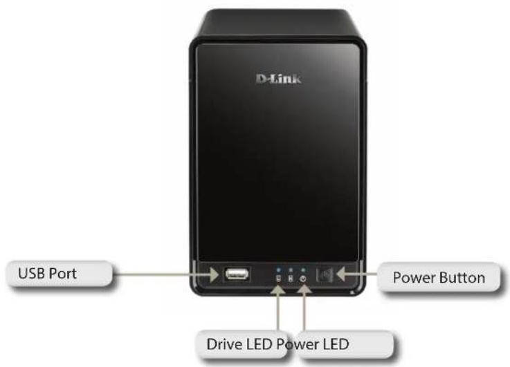
| COMPONENT DESCRIPTION | |
| Power Button | Press once to power on the NVR. Press and hold the button until the LED begins to blink to power down the NVR. |
| Power LED Power | LED will blink when booting up, remain steady during normal operation. |
| Drive LED | These LEDs will be solid BLUE when the drives are connected but inactive. The LEDs will blink when the drives are being accessed, formatted, or synchronized. They will illuminate AMBER if a drive has failed. |
| USB Port USB port for UPS status update. | |
Rear Panel (Connections)
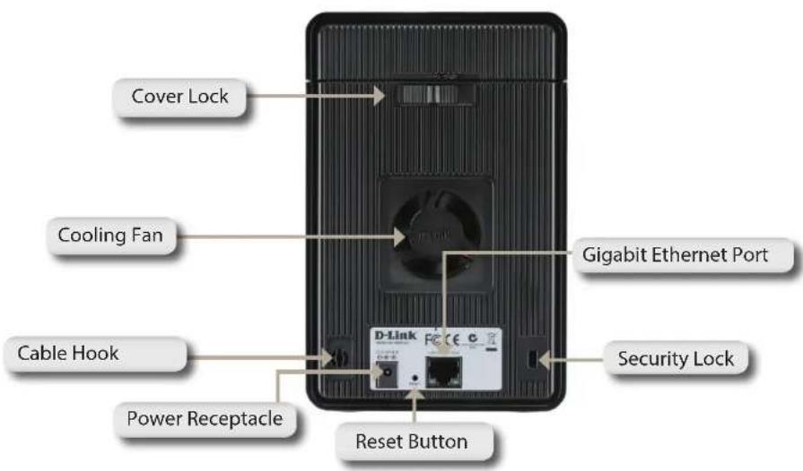
| COMPONENT DESCRIPTION | |
| Cover Lock This lock is used to remove the cover when unlocked. Locking it will prevent the removal of the top cover. | |
| Cooling Fan | The cooling fan is used to cool the hard drives and features speed control. When the unit is first powered on, the fans rotate at a low speed. The fans rotate at a high speed when the temperature rises above 49 °C. |
| Reset Button Press this button for more than 5 seconds to reset the unit to the factory default setting. | |
| Power Receptacle Connect the supplied power cord to the receptacle. | |
| Gigabit Ethernet Port | Use the Gigabit Ethernet Port to connect the device to the local network. The port is equipped with both a LAN LINK (R) and Traffic LED (L) to indicate connectivity and traffic respectively to the local LAN. |
| Security Lock This lock can be used to tie the DNR-322L to a desk to prevent theft. Cables are sold separately. | |
Getting Started NVR Software CD
To get started with the NVR Setup Wizard, insert the supplied CD into your CD-ROM drive.
D-Link
DNR-322L 2-Bay mydlink Network Video Recorder
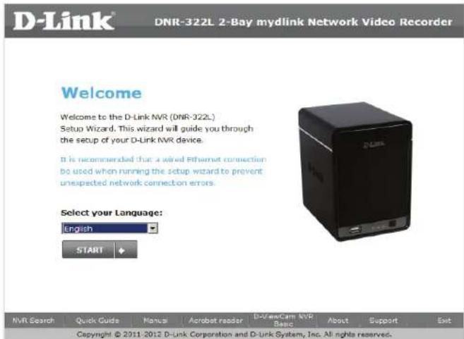
Welcome
Welcome to the D-Link NVR (DNR-322L) Setup Wizard. This wizard will guide you through the setup of your D-Link NVR device.
It is recommended that a wired Ethernet connection be used when running the setup wizard to prevent unexpected network connection errors.
NVR Search
Quick Guide
Manual
Acrobat reader
D ViewCom NVR
About
Support
Copyright © 2011-2012 D-Link Corporation and D-Link System, Inc. All rights reserved.
Setup Wizard
Windows
The following instructions show you how to set up the NVR using your Windows computer. If you are using a Mac computer, go to Setup Wizard - Mac on Page 21.
Simply click Start to go through the Setup Wizard, which will guide you through the installation process from connecting your hardware to configuring your NVR.
Note: The computer used to access the NVR web-based configuration manager must be on the same subnet as the NVR. If your network is using a DHCP server, the NVR will automatically be in the same subnet.
Install the Hard Drives
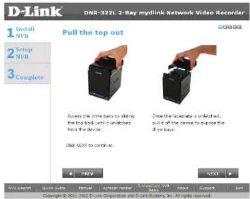
This step shows you how to open your NVR do you can install one or two hard drives. Open your NVR by sliding the cover back and pulling it out. Click Next to continue.
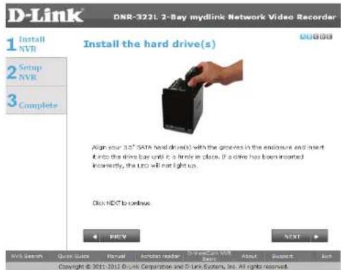
Slide either one or two hard drives into the open hard drive bays of your device. Click Next to continue.
Note: The NVR will use the default login ID of admin and.
Section 3 - Installation
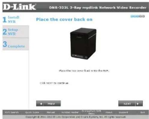
Once the hard drives are installed, you can reattach the top cover. Click Next to continue.
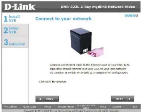
Use the included standard CAT5E Ethernet cable with a RJ-45 connector to connect your NVR to your network. Click Next to continue.
Power and Device Selection
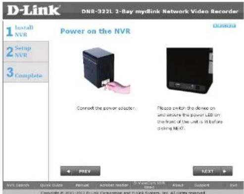
First, connect the power adapter to the power receptor on the back of the NVR. Press the power button located under the faceplate LEDs to turn on the NVR. Click Next on the Setup Wizard to continue.
Select your device from the device selection area. A confirmation window will appear asking you to check if the device's Power LED is solid. If it is solid, select Yes in the confirmation window. Otherwise select No. If the connection is good, then check that the hard drives are installed correctly and have no other issues. Click Next to continue.
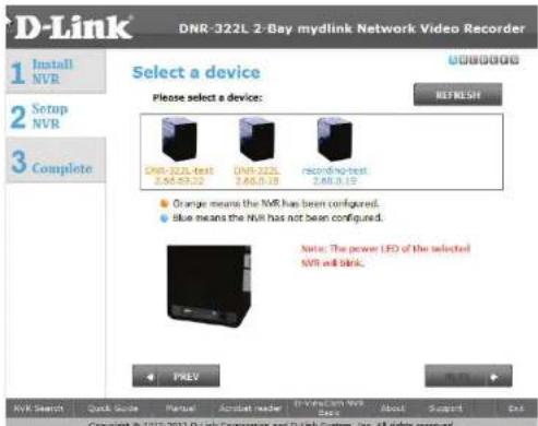
Note: When you select your device from the list, it will cause the LEDs to blink to confirm the device selection.
Note: All configured NVRs are shown with their names in orange, while all NVRs not configured are in blue.
Admin password
This window requests the Admin (administrator) password. If this is the first installation of this device, then leave the password field blank. Click Next to continue.
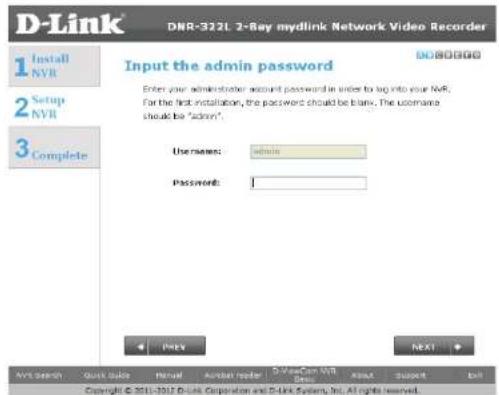
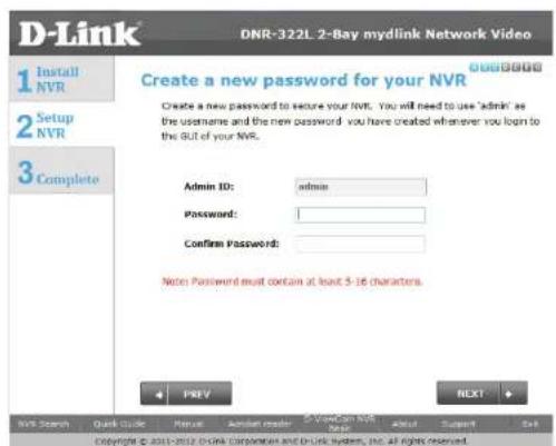
In this step you can create a new password for the Admin username. It is recommended you set a password. Click Next to continue.
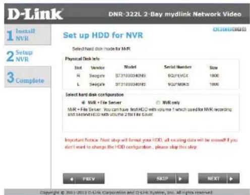
HDD Configuration and Drive Mapping
Select one of the Volume File Systems types. Clicking on the radio button for each file system type will bring up a description. Click Next to continue.
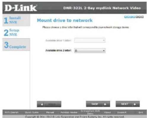
This step allows you to map the volume created as a network drive on your computer. Click Next to continue.
Note:
- Only Volume 2 is able to be formatted as a File Server and mounted to your Windows system as a Network Drive.
- You can also use the NVR Search utility to set up the Network Drive mapping.
Search for Cameras
Please connect your network cameras to your network and power them on.
Click Next to continue.
The NVR will search for your available cameras in your local network (LAN) and will add them to the camera list in the NVR.
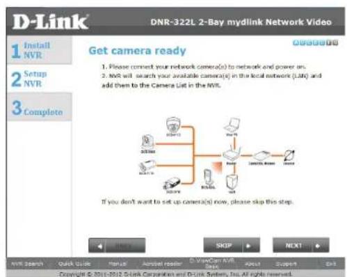
The NVR will search for your available cameras in your local network (LAN) and will add them to the camera list in the NVR.
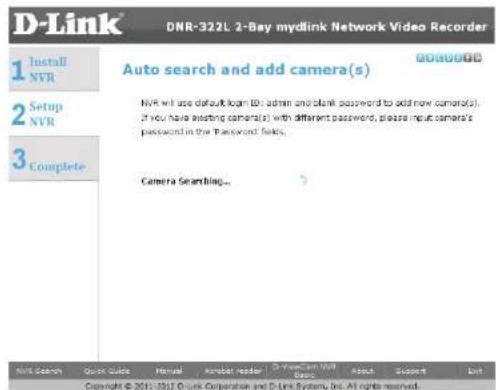
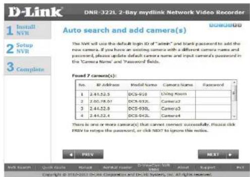
Section 3 - Installation
The NVR will use the default login ID of admin and a blank password to add new cameras. If you have an existing camera with a different camera name and password, please update the default camera name and input the camera's password in the Camera Name and Password fields.
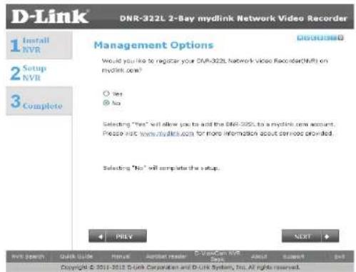
Management Options
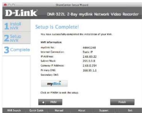
To register the DNR-322L NVR on www.mydlink.com, select Yes and click Next. You will be taken to the Set Up Your Internet Connection page. If you prefer to do this later, select No and click Next to complete the setup. You will be taken to the Setup is Complete page in the next step.
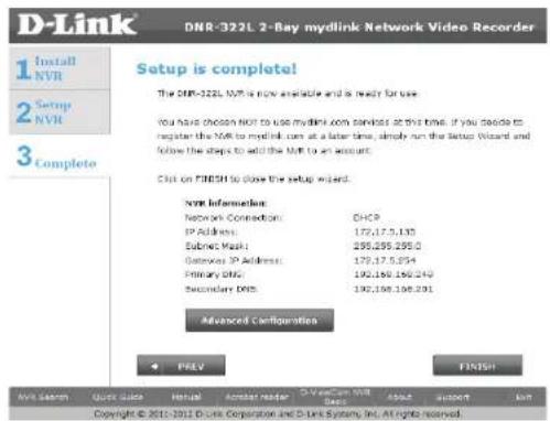
The final window of the installation wizard will show successful completion. Your device is now installed and ready for use.
Click Advanced Configuration to manage and adjust the configuration of the NVR. A browser window will automatically open and allow you to log into the DNR-322L web-based configuration utility.
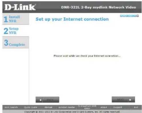
Set up Internet connection
Setup Wizard will try to automatically connect to the Internet.
Note:
If NVR is not able to connect to the Internet, Setup Wizard will allow you to set up the PPPoE or Static IP for Internet connection. Please contact your ISP for setup details.
If you don't have the Internet connection information at this time, or you don't want to connect to the Internet, the Setup Wizard will guide you to go through the Local Access process later.
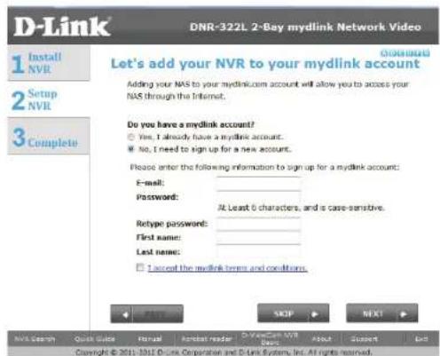
If NVR is able to connect to the Internet, you will need to log in to mydlink. if you already have a mydlink account, click Yes, enter your account details, and click Next.
If you do not have a mydlink account, select No, and fill in the text boxes to create a mydlink account, and click Next.
Section 3 - Installation
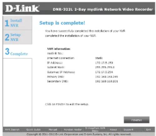
The final window of the installation wizard will show successful completion. Your device is now installed and ready for use.
Note:
Your drives are network mapped, so you will be able to access them under My Computer.
Setup Wizard Mac
The following instructions show you how to set up the NVR using your Mac computer.
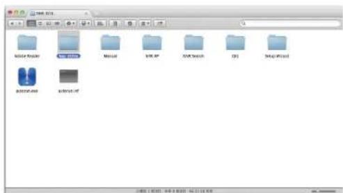
After you have inserted the CD into your computer, go to the CD drive directory, and double-click the Mac Utility folder to enter.
Section 3 - Installation
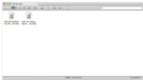
Double-click the DNR-322L Setup Wizard file to start the Setup Wizard, which will guide you through the installation process from connecting your hardware to configuring your NVR.
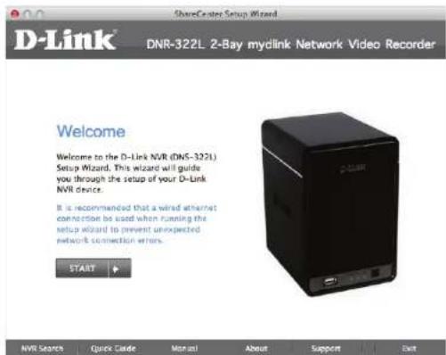
Simply click Start to go through the Setup Wizard, which will guide you through the installation process from connecting your hardware to configuring your NVR.
Note: The computer used to access the NVR web-based configuration manager must be on the same subnet as the NVR. If your network is using a DHCP server, the NVR will automatically be in the same subnet.
Install the Hard Drives
This step shows you how to open your NVR do you can install one or two hard drives. Open your NVR by sliding the cover back and pulling it out. Click Next to continue.
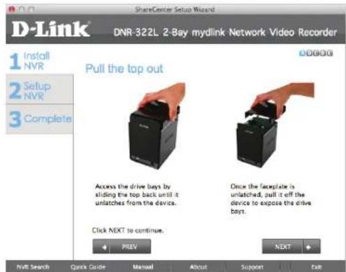
Slide either one or two hard drives into the open hard drive bays of your device. Click Next to continue.
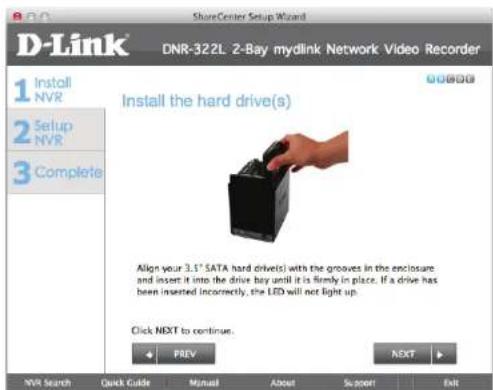
Section 3 - Installation
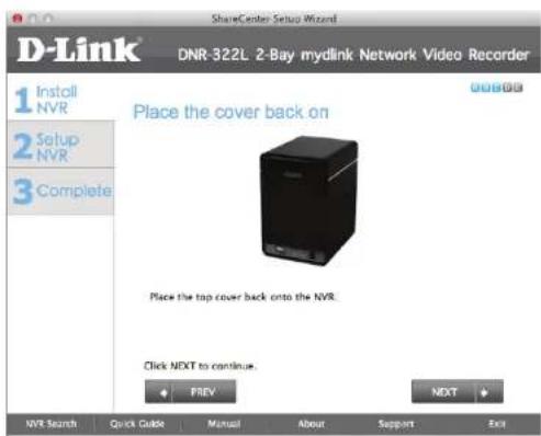
Once the hard drives are installed, you can reattach the top cover. Click Next to continue.
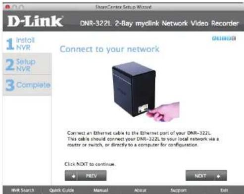
Use the included standard CAT5E Ethernet cable with a RJ-45 connector to connect your NVR to your network. Click Next to continue.
Power and Device Selection
First, connect the power adapter to the power receptor on the back of the NVR. Press the power button located under the faceplate LEDs to turn on the NVR. Click Next on the Setup Wizard to continue.
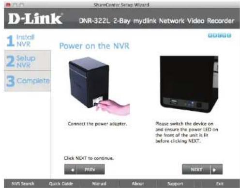
Select your device from the device selection area. A confirmation window will appear asking you to check if the device's Power LED is solid. If it is solid, select Yes in the confirmation window. Otherwise select No. If the connection is good, then check that the hard drives are installed correctly and have no other issues. Click Next to continue.
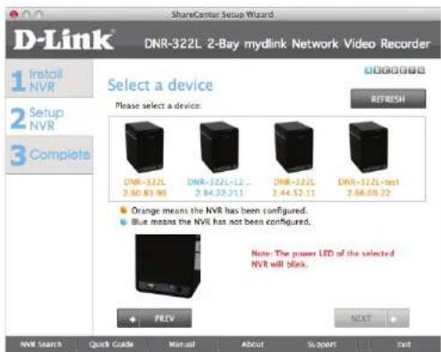
Note: When you select your device from the list, it will cause the LEDs to blink to confirm the device selection.
Note: All configured NVRs are shown with their names in orange, while all NVRs not configured are in blue.
Admin password
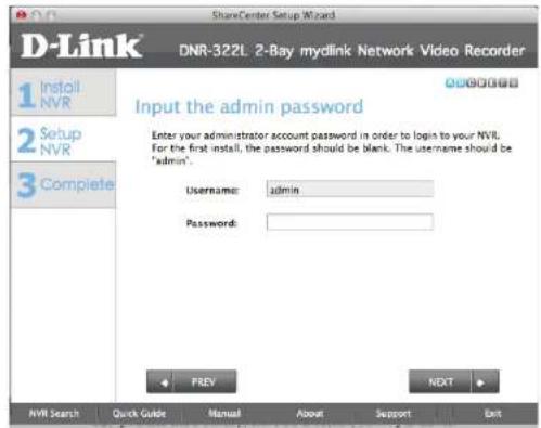
This window requests the Admin (administrator) password. If this is the first installation of this device, then leave the password field blank. Click Next to continue.
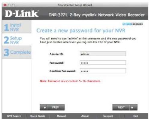
In this step you can create a new password for the Admin username. It is recommended you set a password. Click Next to continue.
HDD Configuration
Select one of the Volume File Systems types. Clicking on the radio button for each file system type will bring up a description. Click Next to continue.
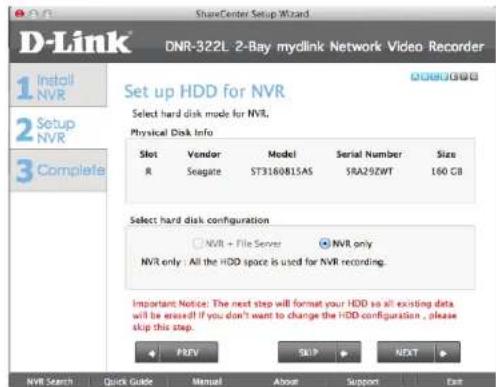
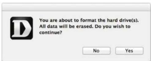
This step allows you to map the volume created as a network drive on your computer. This will format your hard drive and result in all existing data being erased. Click Yes on the confirmation message to continue.
Search for Cameras
Please connect your network cameras to your network and power them on.
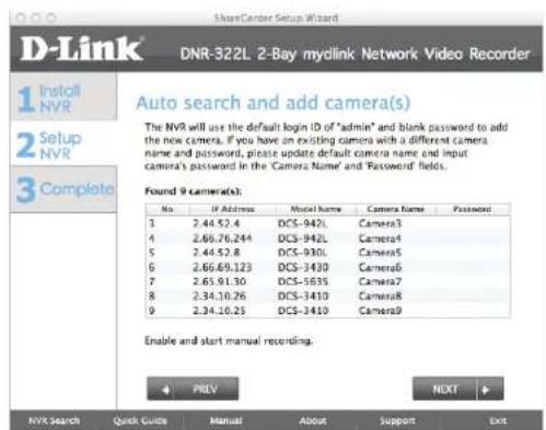
Click Next to continue. The NVR will search for your available cameras in your local area network (LAN) and will add them to the camera list in the NVR.
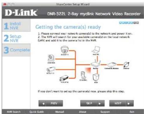
The NVR will search for your available cameras in your local network (LAN) and will add them to the camera list in the NVR.
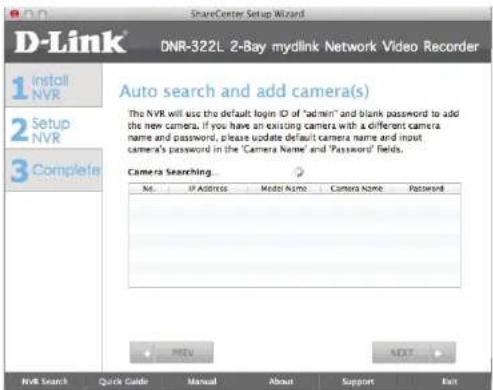
Section 3 - Installation
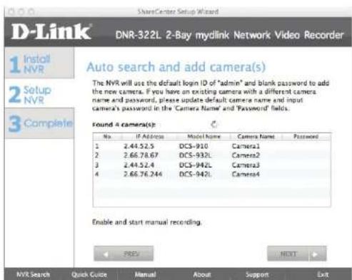
The NVR will use the default login ID of admin and a blank password to add new cameras. If you have an existing camera with a different camera name and password, please update the default camera name and input the camera's password in the Camera Name and Password fields.
Management Options
To register the DNR-322L NVR on www.mydlink.com, select Yes and click Next. You will be taken to the Set Up Your Internet Connection page. If you prefer to do this later, select No and click Next to complete the setup. You will be taken to the Setup is Complete page in the next step.
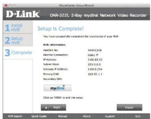
The final window of the installation wizard will show successful completion. Your device is now installed and ready for use.
Click Advanced Configuration to manage and adjust the configuration of the NVR. A browser window will automatically open and allow you to log into the DNR-322L web-based configuration utility.
Set up Internet connection
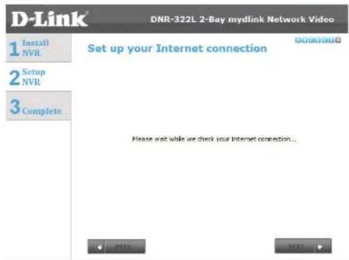
Setup Wizard will try to automatically connect to the Internet.
Note:
If the NVR is not able to connect to the Internet, Setup Wizard will allow you to set up the PPPoE or Static IP for Internet connection. Please contact your ISP for setup details.
If you don't have the Internet connection information at this time, or you don't want to connect to the Internet, the Setup Wizard will guide you to go through the Local Access process later.
If the NVR is able to connect to the Internet, you will need to log in to mydlink.
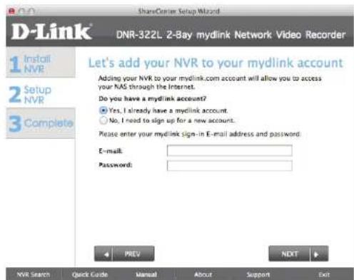
If you already have a mydlink account, click Yes, enter your account details, and click Next.
If you do not have a mydlink account, select No, and fill in the text boxes to create a mydlink account, and click Next.
Section 3 - Installation
The final window of the installation wizard will show successful completion. Your device is now installed and ready for use.
Note:
Your drives are network mapped, so you will be able to access them under My Computer.
mydlink Portal
After registering your NVR with a mydlink account in the NVR Setup Wizard, you will be able to remotely access your NVR from www.mydlink.com. After you log into your mydlink account, you will see a screen similar to this one:
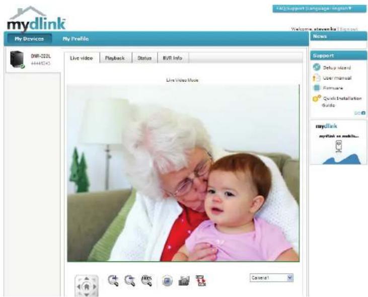
NVR Status
Here, you can see the online status of each NVR. Your online status may be one of the following:

A green checkmark indicates that your NVR is online and ready to use.

A yellow exclamation point indicates that your NVR is online, but the NVR password has changed. You will need to enter your new NVR password to access your NVR again.

A red X indicates that your NVR is offline and currently cannot be accessed remotely.
If your NVR is offline, try the following:
- Check to make sure that the Internet connection to your NVR is working properly.
- Try restarting your Internet router.
- Check your NVR's cable connections and make sure they are secure.
- Check to make sure that the LED on your NVR is lit solid blue.
If you still cannot access your NVR, reset your NVR and run the NVR Setup Wizard again from the CD-ROM included in your package.
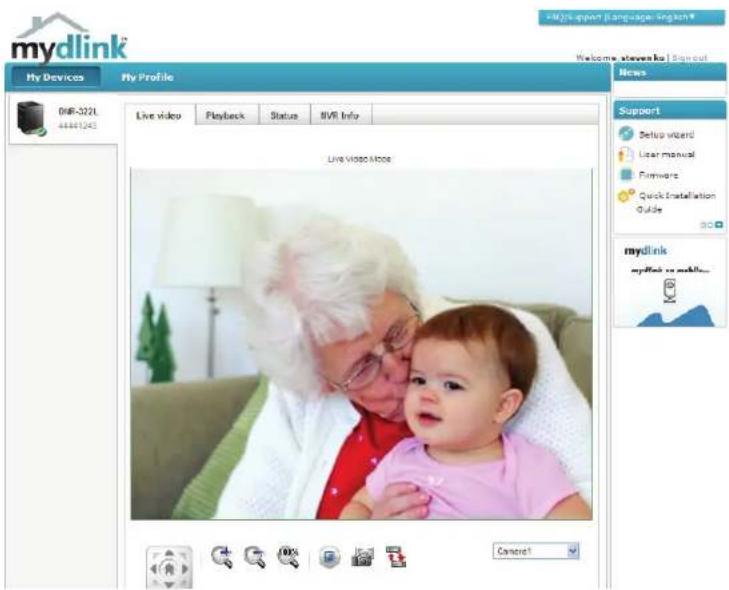
Live Video
In the main part of the screen, the Live Video tab will be selected by default. If the NVR is available, you will need to log in to NVR first. The default login ID is admin and the password is blank. The Live Video feed will then be displayed. You can choose a different camera from the dropdown list. If the NVR is recording, you will see a red dot icon showing on the top right corner on the screen.
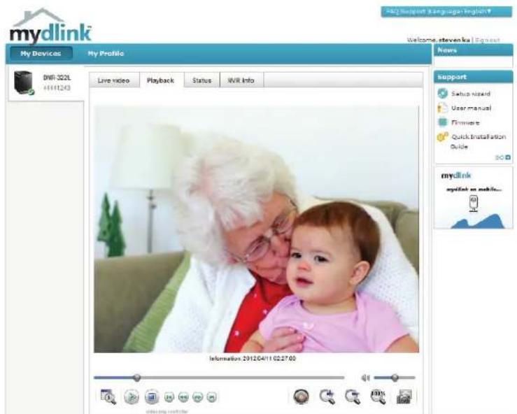
Playback
The NVR Playback tab allows you to access your NVR's playback interface. You can select footage for playback, then zoom in, take screenshots, and adjust the playback speed.
Status
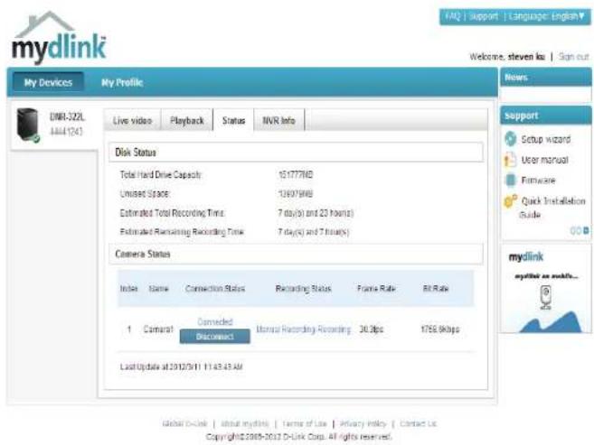
The NVR Status tab allows you to view your NVR's information and camera status. The NVR's hard drive capacity, unused space, total recording time, and remaining recording time are displayed. You can also view the camera status and disconnect it.
Total Hard Drive Capacity: Displays the total hard drive capacity of your NVR.
Unused Space: Displays the free space remaining on your NVR.
Estimated Total Recording Time: Displays the estimated total recording time that can be done on the NVR.
Estimated Remaining Recording time: Displays the estimated remaining recording time that can be done on the NVR.
Camera Status: Displays the connection status, recording status, frame rate, and bit rate of your camera.
NVR Info
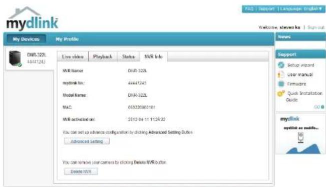
The NVR Info tab shows you information about your NVR.
Device Name: The Device Name is a unique name that can help you to identify it. Clicking on the Device Name will open a window for you to log into your NVR's configuration interface.
mydlink No.: Displays the mydlink number of your device.
Model Name: Displays the model name of your device.
MAC: Displays the MAC address of your device.
NVR activated on: Displays the time and date that your device was added to mydlink.
Advanced Setting: This section takes you to the login page for the NVR's Web GUI Interface. After you log in, you can adjust advanced settings for the NVR.
Delete NVR: This allows you to remove your camera from your mydlink account.
Global D-Link | About mydlink | Terms of Use | Privacy Policy | Contact Us Copyright©2008-2012 D-Link Corp. All rights reserved.
Configuration D-Link NVR Search Utility Windows
For Windows, you can insert the CD and click NVR Search Utility to run another useful setup tool. For Mac, please go on to Page 41. When first powered on, during the initial boot sequence, the device will wait to be assigned an IP address via DHCP. If it does not receive a DHCP-assigned IP address the Auto-IP process will assign a 169.254.xxx.xxx address to the device. If you want to change the IP address before logging in or are unable to connect to the NVR IP address, you can use the NVR Search Utility provided on the product CD to locate the device on your network and make any needed changes.
Network Video The D-Link NVR Search Utility displays any NVR devices it detects on the Recorder: network.
Refresh: Click to refresh the device list.
Configuration: Click Configuration to access the Web-based configuration of the NVR.
LAN: Configure the LAN Settings for the NVR.
Receive DHCP: Select Enable to use DHCP for your LAN IP settings, or Disable to use static IP.
Apply: Click Apply to save and activate the changes to the LAN Settings.
Drive Mapping: Volumes available for mapping are displayed here.
Available Drive Select an available drive letter. Click Connect to map the selected volume. Letters: Click Disconnect to disconnect the selected mapped volume.
About: Click About to view the software version of the NVR Search Utility.
Exit: Click Exit to close the utility.
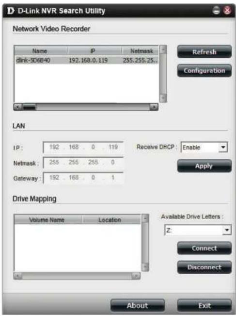
Select the device from the list and click Configuration. This will launch the computer's default web browser and direct it to the IP address listed for the device. Make sure the browser is not configured to use a proxy server.
Note: The computer used to access the NVR web-based configuration manager must be on the same subnet as the NVR. If your network is using a DHCP server and the computer receives IP settings from the DHCP server, the NVR will automatically be in the same subnet.
D-Link NVR Search Utility Mac
Insert the CD, go to the CD directory, then enter the Mac Utility folder. Click the NVR Search Utility file to run this useful setup tool. When first powered on, during the initial boot sequence the device will wait to be assigned an IP address via DHCP. If it does not receive a DHCP-assigned IP address the Auto-IP process will assign a 169.254.xxx.xxx address to the device. If you want to change the IP address before logging in or are unable to connect to the NVR IP address, you can use the NVR Search Utility provided on the product CD to locate the device on your network and make any needed changes.
Network Video The D-Link NVR Search Utility displays any NVR devices it detects on Recorder: the network.
Refresh: Click to refresh the device list.
Configuration: Click Configuration to access the Web-based configuration of the NVR.
LAN:
Configure the LAN Settings for the NVR.
Receive DHCP:
Select Enable to use DHCP for your LAN IP settings, or Disable to use static IP.
Apply:
Click Apply to save and activate the changes to the LAN Settings.
Drive Mounting:
Volumes available for mounting are displayed here.
Click Connect to mount the selected volume. Click Disconnect to unmount the selected volume.
About:
Click About to view the software version of the NVR Search Utility.
Exit:
Click Exit to close the utility.
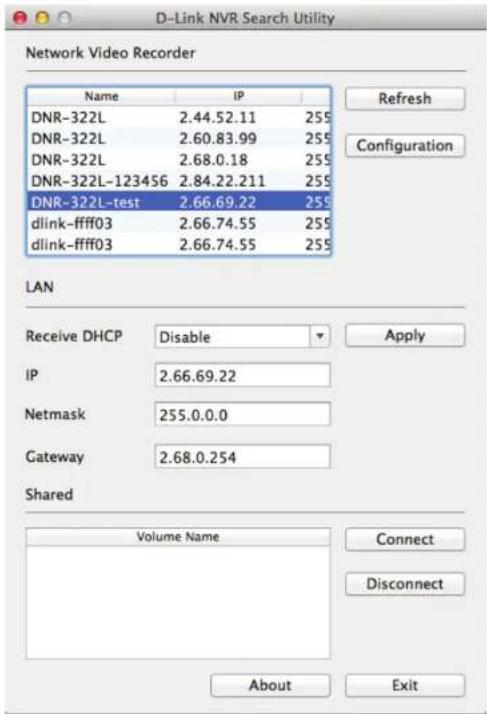
Select the device from the list and click Configuration. This will launch the computer's default web browser and direct it to the IP address listed for the device. Make sure the browser is not configured to use a proxy server.
Note: The computer used to access the NVR web-based configuration manager must be on the same subnet as the NVR. If your network is using a DHCP server and the computer receives IP settings from the DHCP server, the NVR will automatically be in the same subnet.
Web UI Login
This section will show you how to configure your new D-Link NVR using the Web-based Configuration Utility. To access the configuration utility, click the NVR name or IP on the NVR Search Utility or manually open a web browser and enter the IP address of your NVR.
The Login screen will appear:
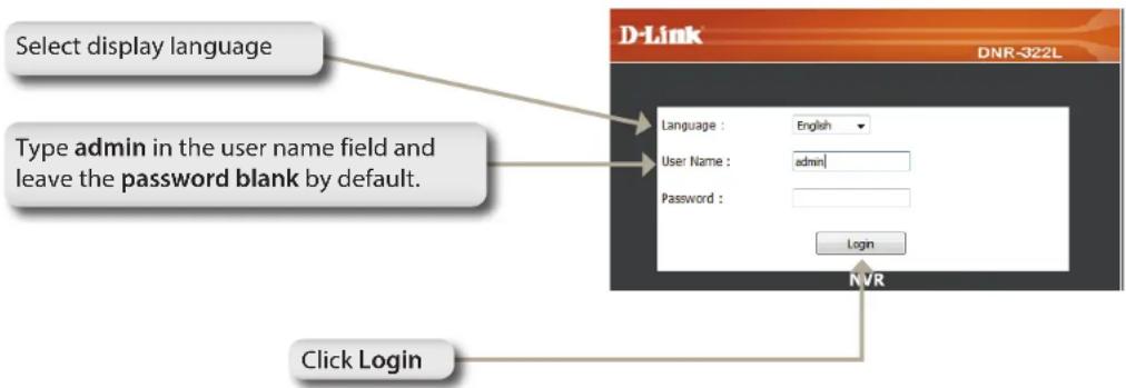
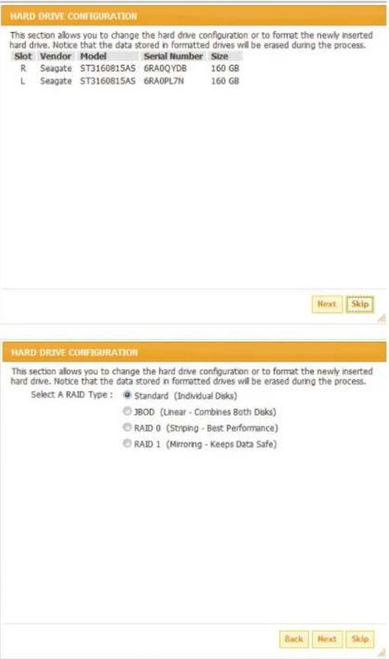
When logging into the NVR for the first time, you will be asked to choose a drive configuration type and format the drives. There are four options: Standard, JBOD, RAID 0 and RAID 1. Standard configures each disk as a separate volume, while JBOD combines both disks into a single volume. See page 52 for more details on using the RAID configurations.
Note: Refer to page 49 for instructions on how to change the password of your admin account.
Configure Hard Drive
If there is one or more HDDs installed, this screen displays the currently installed HDD information.
You must decide on the RAID type you would like to format your HDDs with. Click Next to continue or click Exit to cancel.
Note: Any data on the installed hard drives will be lost by formatting!
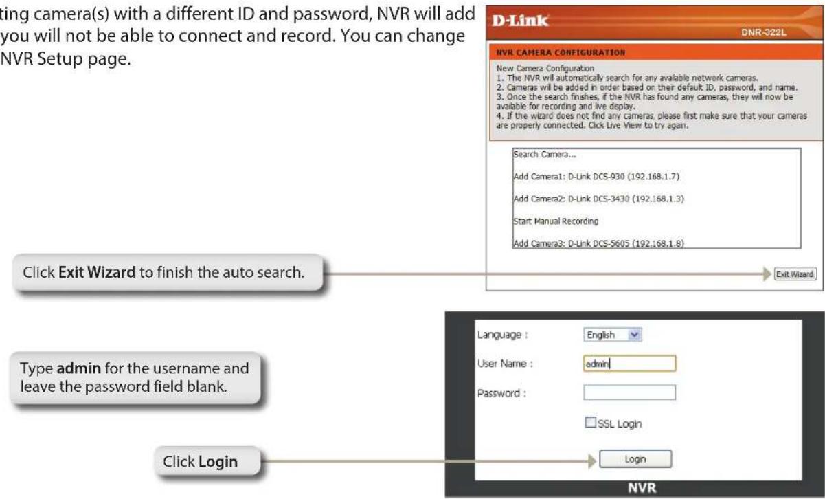
Auto Search Camera
Please connect your network camera(s) to network and power it on.
NVR will search for your available camera(s) in the local network (LAN) and add them to the NVR List in the NVR automatically.
NVR will use the default login ID admin and a blank password to add a new camera(s).
If there are camera(s) found, NVR will start manual recording at the last step.
Note:
If you have an existing camera(s) with a different ID and password, NVR will add the camera(s) but you will not be able to connect and record. You can change the settings in the NVR Setup page.
After login, you will be redirected to the NVR web UI:
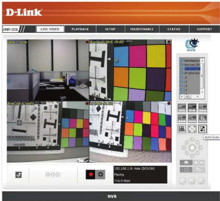
Web UI
The main categories for configuration are located on the menu tabs at the top of the page. These categories include:
- LIVE VIDEO - Shows the live video of network cameras and controls PTZ functions.
- PLAYBACK - Displays recorded video and exports snapshots or video.
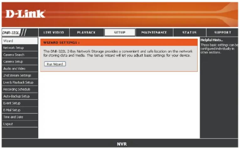
- SETUP - Contains the NVR setup wizard, as well as the LAN configuration settings, camera search, camera settings, recording schedule, auto backup, event settings, time and system settings, and device settings.
- MAINTENANCE - Contains the Administrator account configuration options, Hard Disk management options and RAID configuration options. System configuration, backup, and restore functions are also available.
- STATUS - Contains system, NVR, and event logs.
These pages and their configuration options will be discussed in detail in the following pages of this manual.
Configuring the NVR
BASIC OPERATION
You may run the wizard to configure the setup for your NVR. There are basic and advanced operations. You must first configure the basic operations in order to activate and utilize the features of our NVR.
Step 1: Camera Search - Search for a network camera using UPnP and add it to the NVR camera list.
Step 2: Recording Schedule - Configure a camera for recording and create a detailed schedule. Users can also simply choose Always Record and select connected cameras.
After completing the above settings, the NVR will be fully functional.
ADVANCED OPERATION
Step 1: E-mail Setup - Configure the E-mail address and messages for event notification.
Step 2: Event Setup - Configure event options with various combinations. Events can be triggered in the event of a full hard disk warning. Event actions can be configured so that an E-mail is sent to you when these actions occur.
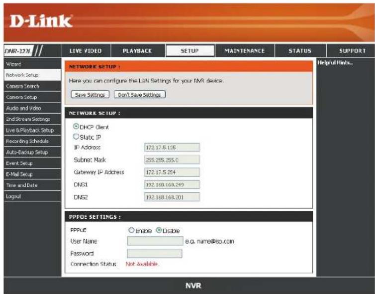
Network Setup
DHCP: Select this connection if you have a DHCP server running on your network and would like a dynamic IP address to be automatically updated to your NVR.
Static IP:
You may obtain a static or fixed IP address and other network information from your network administrator for your NVR. A static IP address will simplify access to your NVR in the future.
IP Address:
The fixed IP address.
Subnet Mask:
The default value 255.255.255.0 is used to determine if the destination is in the same subnet.
Gateway IP
The gateway forwards frames to destinations in a different subnet. Invalid gateway settings may cause the failure of transmissions to a different subnet.
Primary domain name server that translates names to IP addresses.
Secondary domain name server to backup the PPPoE primary one.
Settings:
Enable this setting if your ISP (DSL service) is using PPPoE. You may already have a Username and Password provided by your ISP, or you may need to contact your ISP. The connection status will be determined automatically by the system.
Enable or disable the DHCP server. If your network doesn't have a DHCP server, enable NVR DHCP server for easier local network setup.
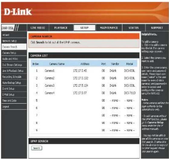
Camera Search
Step 1: Click Search to search for UPnP cameras. The system will list all the available cameras at this moment. Click the + icon to add a camera to your camera list. If the cameras are already added, it will be marked in red.
Step 2: After clicking the icon, the camera setting page will pop up. Click on the camera that you want to add.
Step 3: Enter the camera name, user name, and password of the camera.
Note
- Some cameras will limit the login authority to the administrator only.
- To add cameras without the UPnP function, please go to the camera Setup menu and enter the IP address manually.
- You may not be able to see all the cameras on your first search. It may take a moment for the devices to respond to the UPnP request. Please click Search again if the cameras are not immediately displayed.
Step 4: Click Add to add the selected camera.
Step 5: After clicking Add, the updated information will be displayed in the camera list.
Step 6: Repeat steps 2 through 5 to add other cameras to your list.
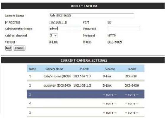
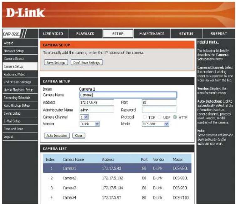
Camera Setup
Step 1: Select the camera which you would like to modify.
Step 2: Modify its information on the top of the page.
Step 3: Click Save Settings.
Step 4: If you would like to replace a camera, select that camera, modify its address, port, user name, and password, and then click Save Settings.
Camera Channel: Select the number of analog cameras supported by one video server from the list.
Vendor: Displays the manufacturer's name.
Auto Detection: If you have already input the camera IP, you may simply click this button to automatically detect camera information (such as the channel, protocol, vendor, and model number).
Note
Some cameras will limit the login authority to the administrator only.
Audio and Video
This section will allow you to configure and modify the audio and video parameters for each camera.
Step 1: Select the camera which you would like to modify in the camera list.
Step 2: The NVR will display the parameters for the selected camera. You can modify the information on this page.
Camera The name of the camera. Name:
Video Format: Select the video format that the camera supports.
Frame rate: Select the frame rate.
Resolution: Select the resolution.
Quality: Select the image quality.
Audio: Check the Enable Audio option for live view and recording.
Go to Web: Click to connect to the web page of the selected network camera for advanced setup. For example, motion detection should be configured via the camera web interface to enable the NVR to receive the trigger message.
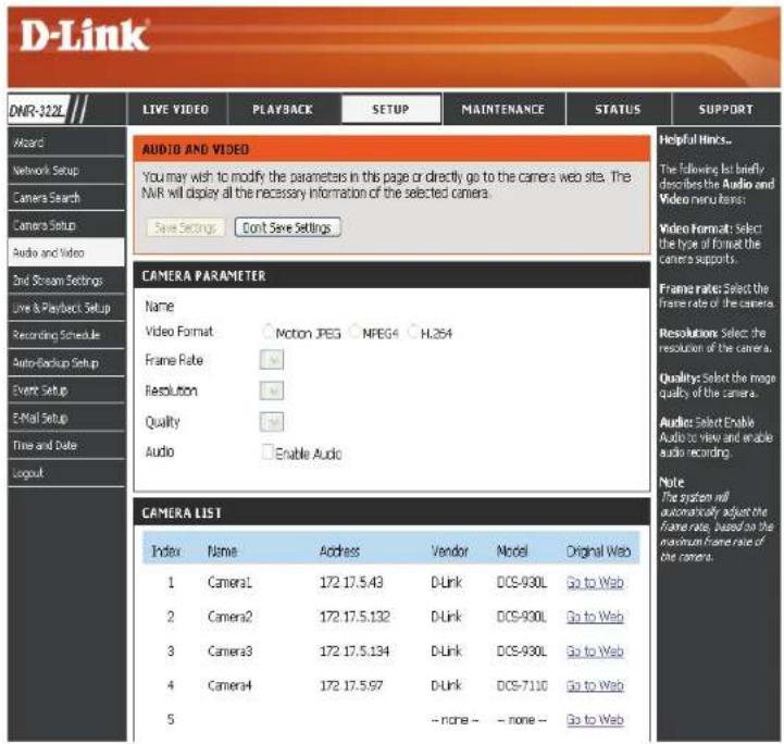
Step 3: Click Save Settings.
Note: The system will adjust the frame rate automatically based on the maximum frame rate which the camera can support.
2nd Stream Settings
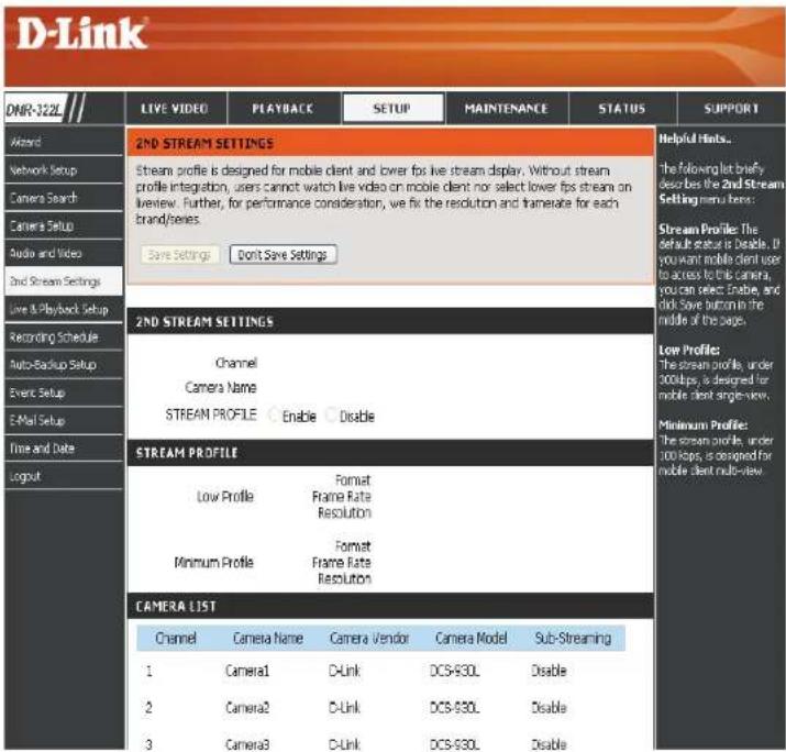
This section will allow you to assign a secondary streaming profile for your cameras, optimized for mobile clients.
Step 1: Select the camera which you would like to modify in the camera list.
Step 2: The NVR will display the profiles for the selected camera. You can enable or disable the profiles on this page.
Channel: The channel of the camera.
Camera The name of the camera. Name:
Stream Enable or disable stream profile for the camera. Profile:
Low Profile: The stream profile is under 300 kbps, and is designed for viewing by a single mobile client.
Minimum Profile: The stream profile is under 100 kbps, and is designed for viewing by mobile clients.
Live and Playback Setup
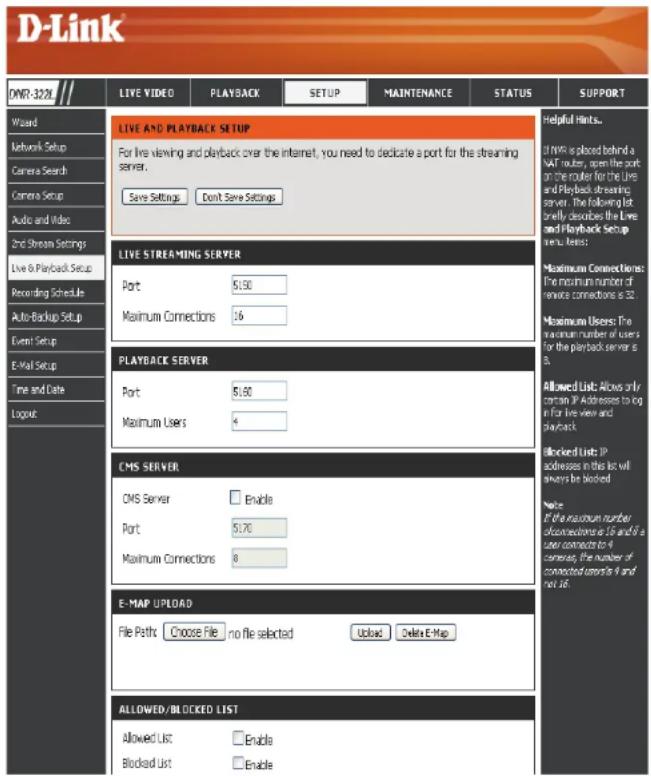
Live Streaming Server
Port: Enter the live streaming transmission port.
Maximum Enter the maximum connections for remote access. The Connections: maximum number of remote connections is 36.
Playback Server
Port: Enter the playback transmission port.
Maximum Enter the maximum number of users who can access Users: playback functions at the same time. The maximum number of users for the playback server is 8.
CMS Server: Upload your map with camera location to NVR. Max. size 20 KB of BMP and JPG file.
NVR supports 3rd party* CMS(Central Management System). It is able to be connected to CMS as a client.
CMS Server: Check the Enable option to enable CMS service. Port: The port number through which the CMS connects to this NVR.
Maximum Connections: The maximum number of allowed CMS connections.
Note: For detail 3rd party information, please contact local D-Link office.
Allowed/ Allowed List: IP addresses in this list can always access your Blocked List: NVR.
Blocked List: IP addresses in this list will always be blocked.
Note: When setting Maximum Connections in Live Streaming Server settings, 1 connection means that 1 user can connect to 1 camera only. If the maximum number of connections is 16 and if each user connects to 4 cameras, then the maximum number of connected users is 4 and not 16.
Recording Schedule
Set Recording Mode
No Record: Turn off recording.
Record by Record according to a schedule. Schedule:
Manual Record: Manual record will always be the method used to record video as it has highest priority. It can be enabled/disabled at the Live Video page.
Automatic Select this option to automatically empty Overwrite: disk space when the disk space is full. This will overwrite the earliest recorded video with the latest video one day at a time.
Store Videos by Set the duration to store recorded video clips. Schedule: After the duration, the clips will be purged.
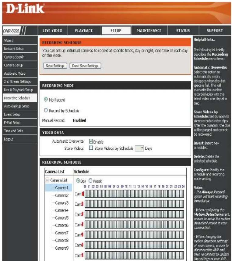
Set Recording Schedule
Set Recording Schedule
Day: Schedule the cameras to turn the recorder on and off at the same time every day according to your preference.
Week: Schedule the cameras differently for each day of the week.
Set up the Step 1: Click the schedule of the camera which Schedule: needs to be modified.
Step 2: Click the column at the bottom of the page.
Step 3: The default recording schedule is from 00:00 to 24:00. If you would like to modify the time slot, click Configure to modify the default settings first.
Insert: Insert new schedules.
Delete: Delete the selected schedule.
Configure: Modify the schedule and recording mode setting.
Copy: Copy the current Day Schedule to other channel(s); copy the current Week Schedule to other day(s) of a week or to other channel(s).
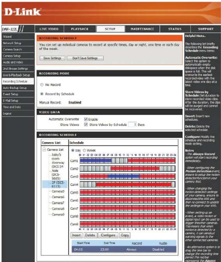
Recording Schedule
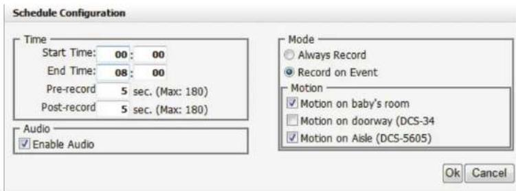
Set Recording Schedule Configuration
Step 1: Enter the desired Start Time and End Time.
Step 2: Enter pre-record and post-record periods for event trigger recording.
Step 3: Check the enable audio box to record audio from your camera (if supported).
Step 4: Choose the recording mode and the trigger source.
Step 5: Press OK to add this new schedule.
Step 6: If you would like to add another new schedule, click Insert.
Note:
- When configuring the Motion Detection event, be sure to set up the motion detection function on your camera first.
• After changing the motion detection settings of your camera, be sure to disconnect the camera from the NVR and then re-connect it to update all new changes.
• Alternatively users can drag the time bar to change the recording period. The red bar represents the Always Record feature and the blue bar represents the Event Recording feature.
Auto Backup
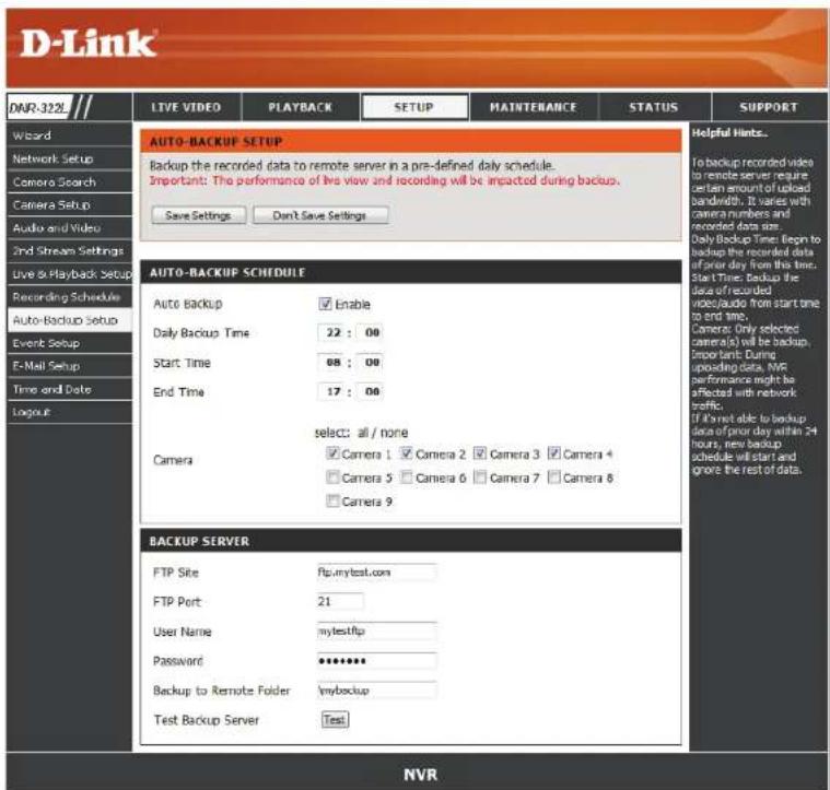
This feature enables you to automatically back up the recorded video of the previous date to FTP site. There are two steps to enable the function, one is to set up Backup Schedule and another is to set up Backup Server.
Auto Backup: Check the Enable option to enable this function.
Daily Backup The daily scheduled time to start the backup Time: process.
Start Time: The start time of recorded video of the previous date.
End Time: The end time of recorded video of the previous date.
Camera: Select the channel(s) to back up.
Note:
The system backs up recorded video files one by one. If the connection between the unit and the FTP server is normal, but some problems with FTP hinder the system from writing files on FTP, the system would try to back up each file three times before starting to back up the next file. If the connection is lost, the system will wait for the connection, so no file would be skipped.
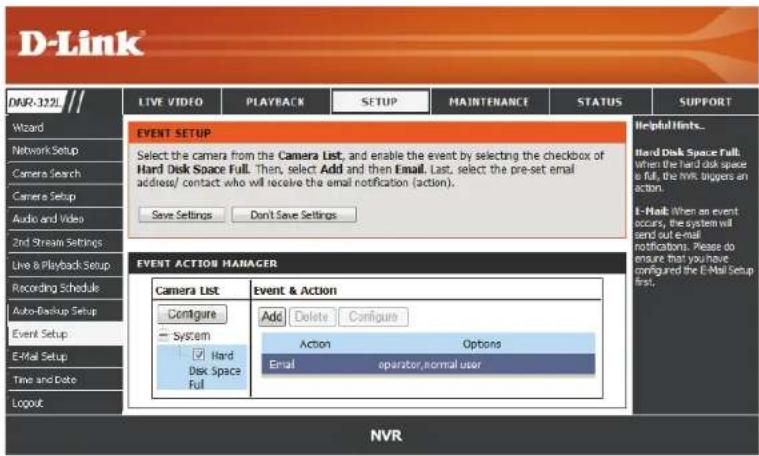
Event Setup
Step 1: Select the event below.
Hard Disk When the Overwrite function is not enabled, Space Full: the NVR will stop recording when the HDD is full.
Step 2: Click Add to set up the actions of the event.
E-mail: When an event occurs, the system will send an E-mail to the preset contacts.
Push When an event occurs, an instant message will Notification: be sent to registered mobile clients. Mobile users can view recorded video of the event through their mobile clients.
Step 3: Click the action, and then click Configure to modify the details of that action if necessary.
Step 4: Repeat step 2 through 3 to add more actions.
Backup Server
FTP Site: The IP or domain name of the remote FTP server.
FTP Port: The remote FTP site port number, default FTP port is 21.
User Name: The user name to log into the FTP server.
Password: The password to log into the FTP server.
Folder: The folder format is FolderName, FolderName/SubFolderName, and so on.
Test Backup After setting up all the information, click Test FTP and the system will create a folder to FTP. Please check it after testing. Server:
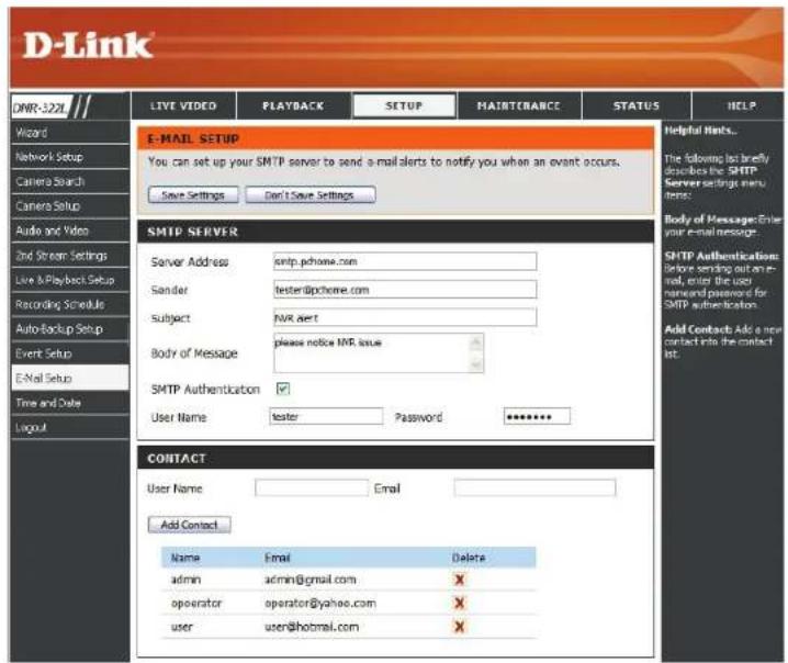
E-mail Setup
Server Address: SMTP (Simple Mail Transport Protocol) server IP address.
Port: Specify the port number of the email server. The default number is 25.
Use SSL: Check this if your email server uses SSL protocol.
Sender: Sender information.
Subject: E-mail subject.
Body of Message: E-mail content.
SMTP Provide the user name and password to the Authentication: SMTP server for identification before sending e-mail.
User Name: Input the SMTP server login user name.
Password: Input the SMTP server login user password.
Send Testing Mail: Click this button and the system will send a test mail to the sender. Please check it after testing.
Add Contacts
Step 1: Insert the name of a new contact.
Step 2: Insert the E-mail address of this new contact.
Step 3: Click Add Contact.
Step 4: Click Save Settings to save the new contact list.
Time and Date Setup
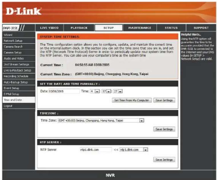
Manually Set the Time and Date: Enter the complete time and date settings manually. Click Save Settings to apply the settings.
Set Time From Click Set Time to have the NVR set its own My Computer: clock according to the time on your computer.
Time Zone Select your time zone from the pull-down list. Settings: Click Save Settings to apply the settings.
There are three choices for setting the time.
NTP Server: Select or enter an NTP Server here. An NTP Server is a server on the Internet that maintains time. The NVR will contact the server you entered and receive the correct time. Click Save Settings to save your entries.
Maintenance User Management
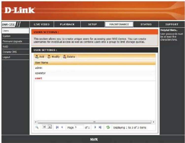
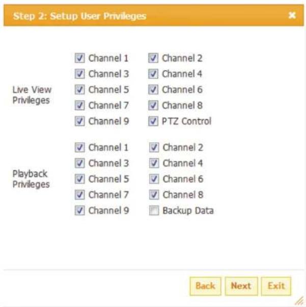
Add New User
Step 1: Input the new user name.
Step 2: Input the password. Type the password again to confirm.
Step 3: Select the live view cameras and PTZ/ IO
Control functions which this user can access.
Step 4: Select the playback channels and Backup Data function which this user can access.
Step 5: Click Finish to create a new user.
Note
The Administrator account can configure all functions of the NVR. This account cannot be deleted. The default password for admin is blank. Setting a password after the first login is strongly recommended. If the administrator password is lost, you may hold the reset button on the rear panel of the device to reset the NVR to factory defaults.
Note: This will erase all the previously-saved settings.
User List
Change User's Password
Step 1: Select the user name you want to modify and click Modify.
Step 2: Input the password of the user. Type the password again to confirm.
Step 3: Click Finish to save. Click Exit to abort.
Delete A User
Step 1: Select the user name you want to delete and click Delete.
Step 2: In the confirmation box, click OK.
System
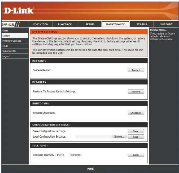
Users can save the NVR configuration to a file and restore it when necessary, such as restarting the NVR in the event of a crash. Reset the NVR to restore all configurations to factory default.
Restart: If the NVR is malfunctioning or crashes unexpectedly, click Restart on the NVR. Restarting the NVR will take about one and a half minutes.
Default: This will reset all configurations to factory default.
Shutdown: This will shut down the NVR.
Save All the configurations can be saved as a file to Configuration: the specified location. Click Save to save the file.
Load Users can restore the configuration file after Configuration resetting to factory default file.
File: Click Browse to select the configuration file and restore it by clicking Load.
Idle Time: When the administrator enters all the Setup pages, except the Live Video and Playback Page, the NVR will keep track of the idle time when the user is not active. If this inactive period reaches a certain time, the user will be logged out and will have to log in again for security purposes. Change the period of idle time here.
RAID
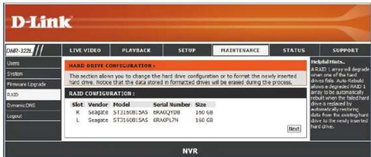
NVR will show the information of installed HDDs first. Click Next to select new RAID configuration.
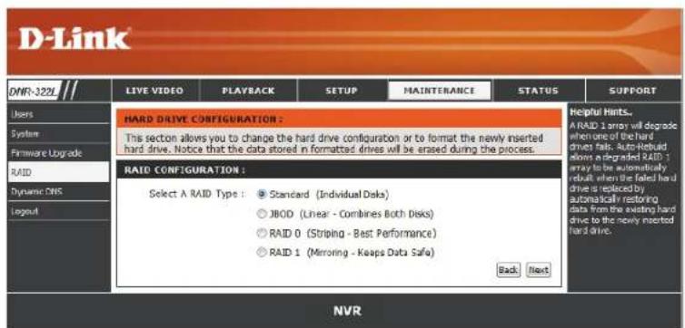
Choose from four different hard drive configurations in this section. Begin by clicking Set RAID Type and Re-Format. Note: All data will be lost during this process.
Standard: Creates two separate volumes (or one volume if only one hard drive is present). Each hard drive has its own volume.
Note:
Only Standard mode can create the Volume2, which is available as a File (Samba) Server. Use the NVR Search utility to mount the File server to your Windows system.
JBOD: Combines both hard drives in a linear fashion which will create one large volume geared towards maximum available space.
RAID 0: Combines both hard drives in a striped fashion which will create one large volume geared towards maximum performance.
RAID 1: Mirrors the hard drives for redundancy. If one hard drive fails, the other still has all the data. Replace the failed hard drive and it will re-mirror, restoring maximum data protection.
What is RAID?
RAID, short for Redundant Array of Independent Disks, is a combination of two or more disks with the aim of providing fault tolerance and improving performance. There are several different levels of RAID, with each providing a different method of sharing or distributing data amongst the drives. The NVR supports RAID levels 0 and 1.
RAID 0 RAID 0 provides data striping, which spreads out blocks of data over both drives, but does not provide data redundancy.
Although performance is improved, the lack of fault tolerance means that if one drive fails, all data in the array will be lost.
RAID 1 RAID 1 provides mirroring over both disks, with the same read/write speed of a single disk. A RAID 1 array can only be as large as its smallest member disk.
Because the data is stored on both disks, RAID 1 provides fault tolerance and protection, in addition to performance advantages.
RAID 0
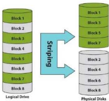
flowchart
graph LR
    A["Logical Drive"] --> B["Blocking"]
    B --> C["Physical Disks"]
    subgraph Logical Drive
        D1["Block 1"] --> D2["Block 2"]
        D3["Block 3"] --> D4["Block 4"]
        D5["Block 5"] --> D6["Block 6"]
        D7["Block 7"] --> D8["Block 8"]
    end
    subgraph Physical Disks
        E1["Block 1"] --> E2["Block 3"]
        E3["Block 5"] --> E4["Block 7"]
        E5["Block 2"] --> E6["Block 4"]
        E7["Block 6"] --> E8["Block 8"]
    end
    D1 <--> E1
    D2 <--> E2
    D3 <--> E3
    D4 <--> E4
    D5 <--> E5
    D6 <--> E6
    D7 <--> E7
    D8 <--> E8
    style Logical Drive fill:#90EE90,stroke:#333
    style Physical Disks fill:#90EE90,stroke:#333
RAID 1
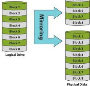
flowchart
graph TD
    A["Logical Drive"] -->|Mirroring| B["Physical Disks"]
    subgraph Mirroring
        C1["Block 1"] --> D1["Block 2"] --> E1["Block 3"] --> F1["Block 4"] --> G1["Block 5"] --> H1["Block 6"] --> I1["Block 7"] --> J1["Block 8"]
    end
    subgraph Physical Disks
        K1["Block 1"] --> L1["Block 2"] --> M1["Block 3"] --> N1["Block 4"] --> O1["Block 5"] --> P1["Block 6"] --> Q1["Block 7"] --> R1["Block 8"]
    end
Dynamic DNS
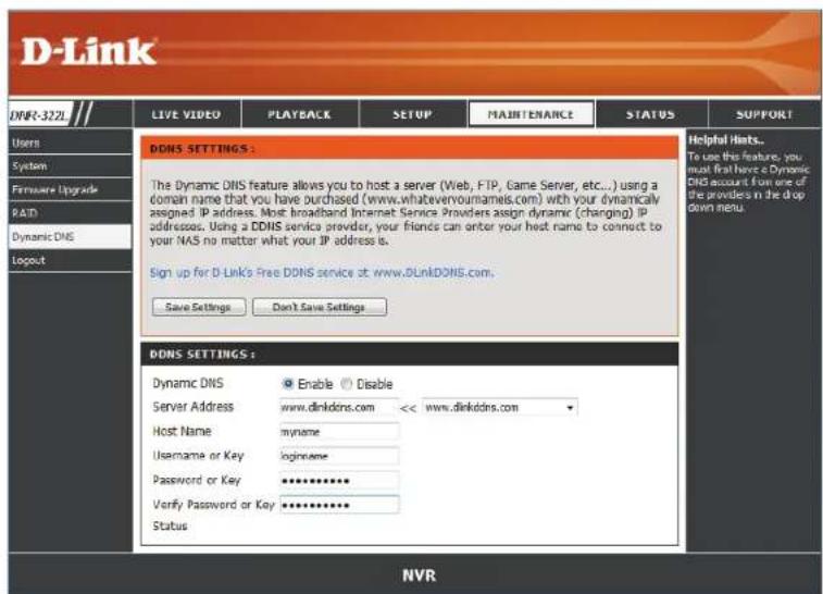
Enable this option only if you have purchased a domain name and registered with a dynamic DNS service provider. The following parameters are displayed when the option is enabled.
Server Select a dynamic DNS service provider from
Address: the pull-down list.
Host Name: Enter your host name. For example: myhost.mydomain.net.
Username or Key: Enter the username or key provided by your service provider. If the Dynamic DNS provider supplies only a key, enter that key in all three fields.
Password or Enter the password or key provided by your Key: service provider.
Verify
Password or Key: Re-type the password or key provided by your service provider.
Status: Displays the current status of connection to the DDNS server.
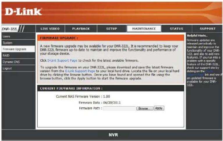
Firmware Update
The device firmware can be upgraded from this page. The firmware update must be saved on the local hard drive of your computer. Click Browse to search the local hard drive for the firmware update file. Click Apply to upgrade. You may always check for firmware updates on the D-Link Support Page.
Status
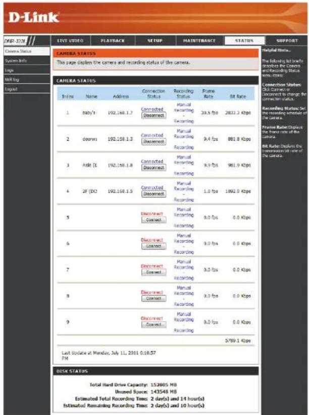
Camera Status
This page displays the connection and recording status of your cameras.
Connection Status: Shows the camera connection status. The user can click Connect or Disconnect to change the connection status.
Recording Status: Shows the recording schedule and current recording status of the cameras. Please note that if the camera is disconnected, the recording may continue but will produce blank video.
Frame Rate: Displays the frame rate of the camera.
Bit Rate: Displays the transmission bit rate of the camera.
Note: If the Frame Rate or Bit Rate is too low, please check the network configuration between cameras and NVR. If the bit rate is too high, it will cause the Live Video display to slow down or lag. If this is the case, please modify the quality or bitrate setting in the camera web GUI accordingly.
Disk Status: Shows the hard drive space and estimated remaining recording time status.
Note: The recording time information is estimated by the current bit rate. This may change each time a user refreshes this page.
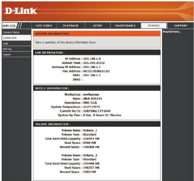
System Info
This section displays the summary information of your NVR.
LAN Displays the local network settings of the NVR. Information:
Device Displays the device name and current Information: temperature of the NVR.
Hard Drive Displays the hard drive information, including Information: the disk mode, total size, and used and remaining drive space.
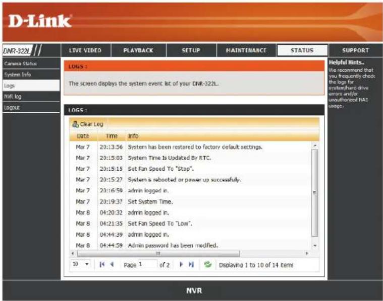
System Log
This page displays the system event list of your NVR. The System Log is different from the NVR Log as it includes the following items:
- User login/logout
- Modify/delete account
- System restart
- System reset to default
- System firmware update
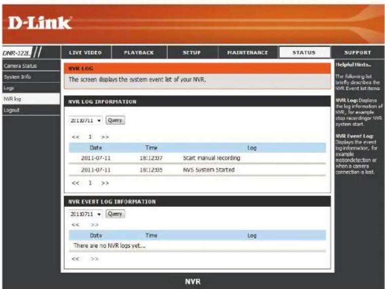
NVR Log
This NVR Log displays the event log information.
NVR Log: Displays the NVR log information such as when recording stopped or NVR system start.
NVR Event Log: Displays the event log information such as motion detection or lost camera connection.
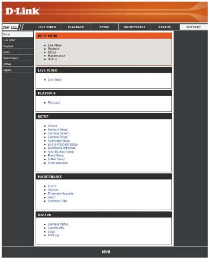
Support
The NVR Help page provides a list of support topics.
Live Video
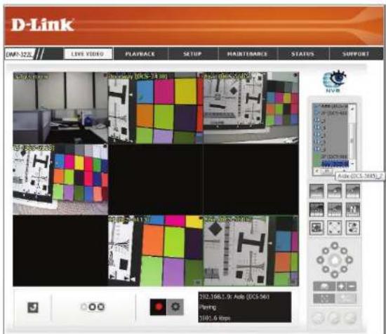
This section will enable you to configure and view the live video from your network cameras.
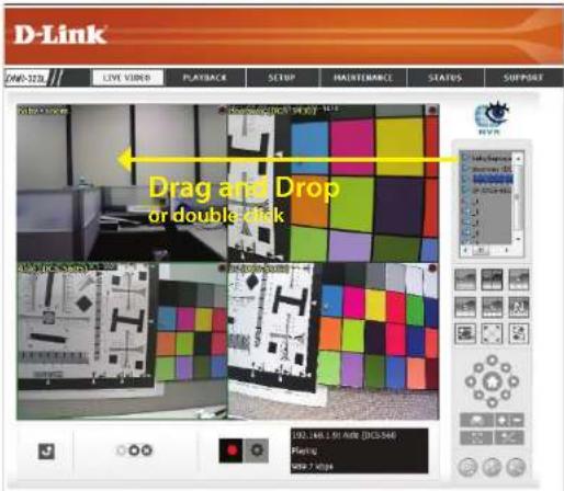
Set up Live View
Step 1: Click LIVE VIDEO at the top of the menu.
Step 2: Select a camera(s) from the camera list on the right and then drag it to the location to where you wish the image to be displayed.
Step 3: Users can change the video display position by dragging it to another position.
Note
-
The selected video will be marked with a green line.
-
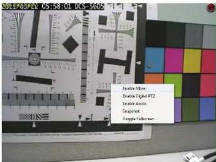
Enable Digital PTZ: Right-click on the video and click on Enable Digital PTZ. Click the + or - button to zoom in or zoom out the view. The lower right square flashing on the video grid indicates the correspondent view of the camera.
-
If the camera supports PTZ, users can control the selected camera from the PTZ panel. Users can also right-click on the video and check Enable Move to control the PTZ function directly. Please note that when Enable Move is checked, the video will be marked with a red outline. This indicates that another camera cannot be adjusted until the PTZ function has been deactivated.
-
If the camera supports audio, users can check Enable Audio from the right-click menu and listen to live audio of this channel.
-
Snapshot: Right-click on the video and select the snapshot function to capture a specific video image immediately.
-
Right-clicking on the video will show the option to Toggle to Full Screen. Press the ESC button on the keyboard to return to normal display.
Section 6 - Live Video
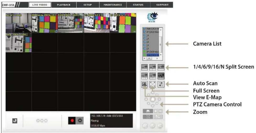
1/4/6/9/16/N
Split Screen:
User can choose to view 1, 4, 6, 9, 16, or NxN cameras at a time.
Note: Maximum physical cameras only support 9 channels, other channels are the Duplicated channel.
View E-Map:
Display your emap file. Max. size 20 KB as a BMP and JPG file.
Auto Scan:
Activate auto scan to rotate the channels on the display screen. For instance, you may select to show only a 4-split screen on the live view, while connecting 16 channels to the system. With autoscan function, you are able to see all 16 channels by turns.
Full Screen:
Select to display the video with full screen. Press the ESC key on the keyboard to return to normal display.
PTZ Camera
You may control the camera view by utilizing the PTZ camera control panel to adjust the camera's view. This is only available with cameras that support the PTZ function.
Control:
Click the + or - button to zoom in or zoom out. This option is only available with cameras that support the optical zoom function.
Section 6 - Live Video
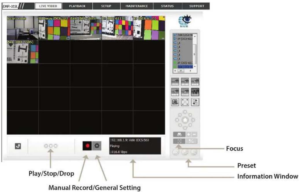
Preset: Click the Set button to set a preset position for a camera with PTZ support. Users can give the specified position a name and store it in the preset position list. Click the Go button to go to the preset position. This is only available with cameras that support the PTZ function.
Focus: Click the +- button to adjust focus or select the auto focus.
Play/Stop/Drop: Select a camera/video and click this button to play/stop/disconnect a particular channel.
Information Display Display video information including camera name, video status, and bit rate for a selected channel. Window:
Manual Record: Click to start recording immediately. Click again to stop recording.
General Setting
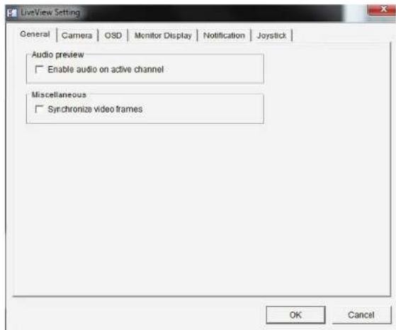
General
- Check the Enable audio on active channel option to enable audio streaming on active channel. This function synchronizes with right clicking on the camera to enable audio.
- Check Synchronize video frames to avoid the tearing problem from occurring in the video display while increasing the CPU load.
Camera Setting
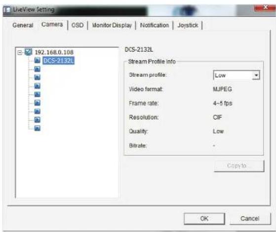
The DNR-322L allows you to adjust the stream for remote live streaming. Lowering the streaming profile allows for more efficient transmission and conserves bandwidth.
Note: Stream Profile is the second stream of the camera. Not all cameras feature a second stream.
- Select your camera device from the list on the left.
- Select from Original, Low, and Minimum for the Stream Profile. Low streams at a rate of under 300 kpbs while Minimum streams at under 100 kbps. If you would like to use this option for another camera on the list, click Copy To.
- Click OK to save this setting.
OSD (On-screen display) Setting
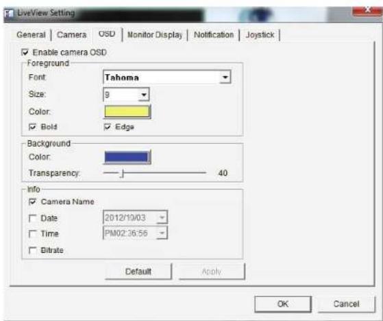
- Check the Enable camera OSD option.
- Set the foreground and background settings of the OSD.
- Select which types of information will be displayed on the screen.
- Click Apply to preview the result.
- Click Default to go back to the default settings if necessary.
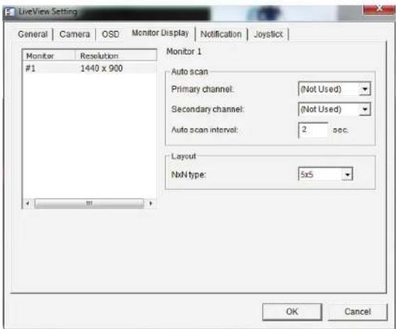
Monitor Display Setting
- Select Primary channel which will always be on the screen when activating auto scan; while select Secondary channel which has second priority when activating auto scan. Enter the time interval for auto scan.
- Select the screen division of NxN type.
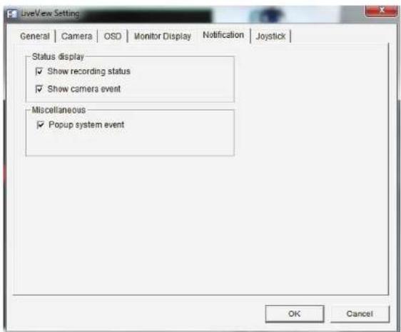
Notification
- Check Show recording status to show the crystal ball with recording status on monitor display.
- Check Show camera event to display a message for detected camera events on the correspondent screen.
- Check Popup system event to have a system event message dialog pop up as a warning when a system event occurs.
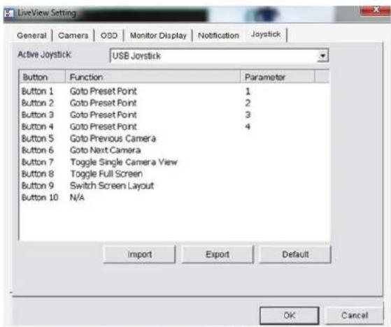
Set up Joystick Control
The DNR-322L supports USB joystick control.
Function: You can choose the function from the drop-down menu for the button of the joystick.
Parameter: Choose the preset point from the drop-down menu.
Default: Click to back to default setting.
Import: Click to import the settings.
Export: Click to export the settings.
After you have finished setting up the joystick, you can use it to control the PTZ camera in the Live View window.
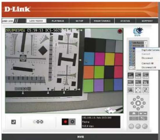
Multiple view
You can right-click on the camera list to duplicate and connect/disconnect designate cameras, and do other functions.
Duplicate Select the duplicate camera function to create multiple views. Camera: The duplicated camera will be shown with a green indicator. Combine this function with digital PTZ so users are able to enlarge different spots and view them in different channels. This whole view can be recorded.
Connect/ Click to connect or disconnect the designated camera. Disconnect:
Connect All/ Click to connect or disconnect all cameras. Disconnect All:
Playback
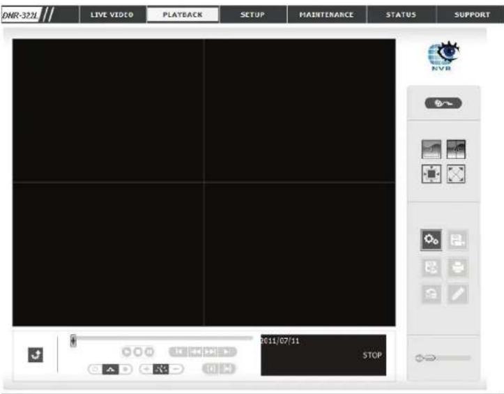
This feature allows you to search and play back the recorded video.
Play the Recorded Video
Step 1: Be sure that you have set the schedule/recording event first.
Step 2: Click the PLAYBACK tab at the top of the menu.
Step 3: Click the Open Record button.
Step 4: The Record Display Window will show information about the available video clips. Select the date you would like to find the video records of.
Step 5: Highlight the video records that you would like to review.
Step 6: Click the OK button.
Section 6 - Live Video
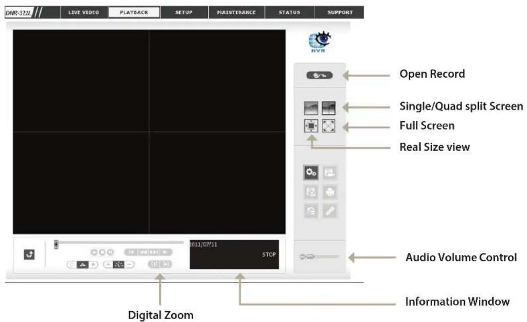
Single/Quad User may view a single camera or 4 cameras at a time. The DNR-322L only supports 1 camera playback.
Split Screen:
Full Screen: Select to display the video with full screen. Press the ESC key on the keyboard to return to normal display.
Information Display video date and time, cue in/ out points, time and speed.
Window:
Audio Volume Adjust the sound level.
Control:
Digital Zoom: Click the icon to digitally zoom in or out. Every camera can use this function.
Section 6 - Live Video
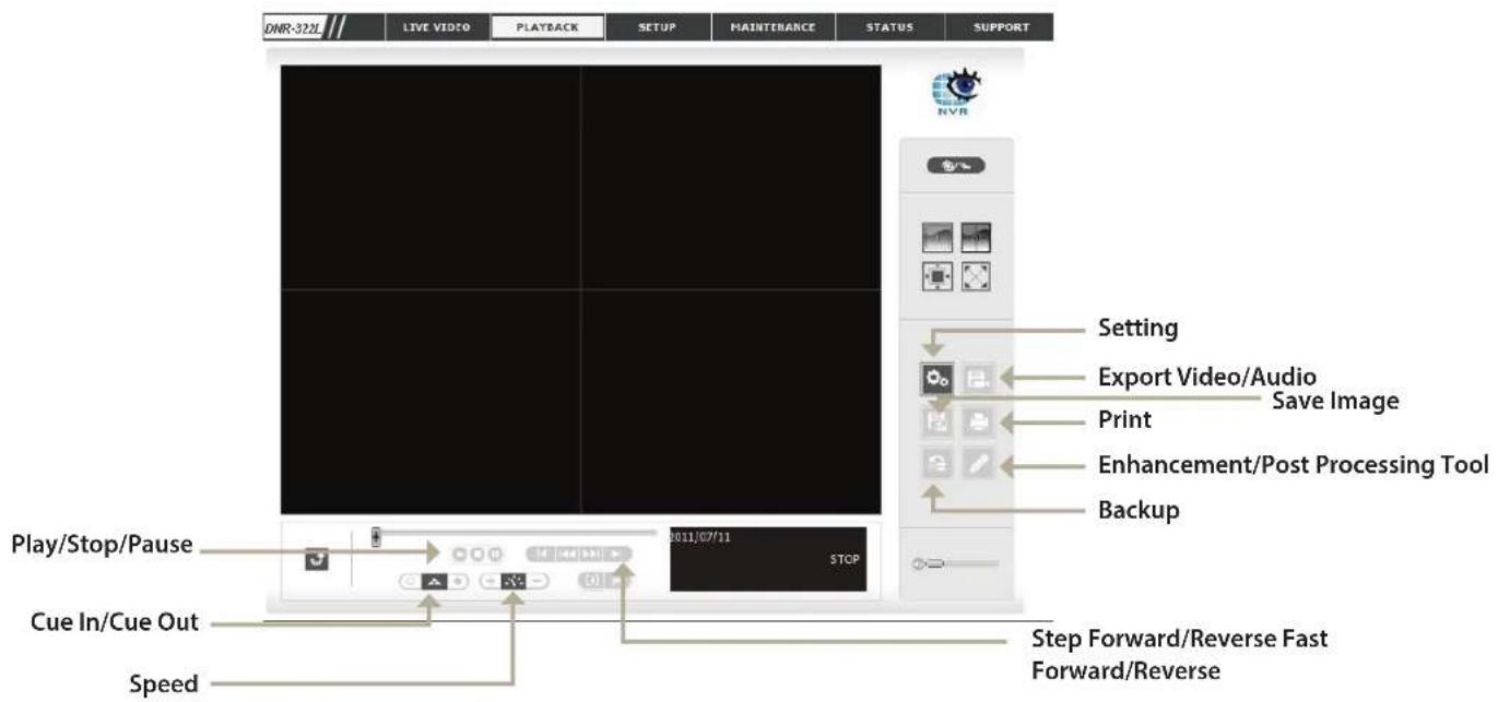
Play/Stop/Pause: Select a camera/video and click this button to play/stop/pause a particular channel.
Speed: Click the + or - button to increase or decrease the playback speed.
Cue In/Cue out: Click the Cue In or Cue Out button to set the period for Save Video.
Step Forward/Reverse: Click to pause the playback and move to next frame or last frame.
Fast Forward/Reverse: Click to pause the playback and move to next minute or last minute.
Open Record and Setting
Click the Setting button to change the settings of Playback.
Record Display
Calendar View: Recordings are displayed as a calendar.
List Control: Recordings are displayed as a list.
Play
Play when open: When selecting this option, the system will start playing the video clip whenever a record is withdrawn.
Auto skip when Check the option to set up the system to record motion only automatically skip to the points where mode: motion is recorded.
Next Interval: Set the interval for the video to go forward when you click the Forward button on the control panel.
Previous Interval: Set the interval for the video to go back when you click the Reverse button on the control panel.
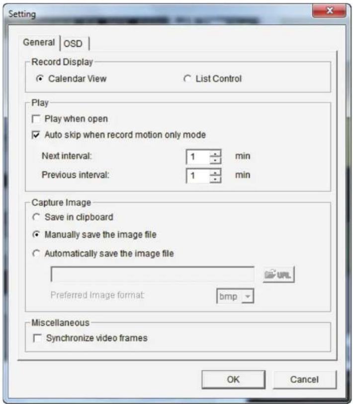
Capture Image
Save in Clipboard: The image will be saved in the clipboard and can be pasted to other applications.
Manually save the image file: You can manually select where you would like to save the image, name the saved file, and choose the desired format for the image.
Automatically save by pre-setting a path/URL and the image format, the system will automatically save the image accordingly the image file: when you click the Save Image button in the control panel.
Miscellaneous
Check the Synchronize video frames option to avoid the tearing problem occurring in video display while increasing the CPU loading.
Search the Recorded Video to Playback
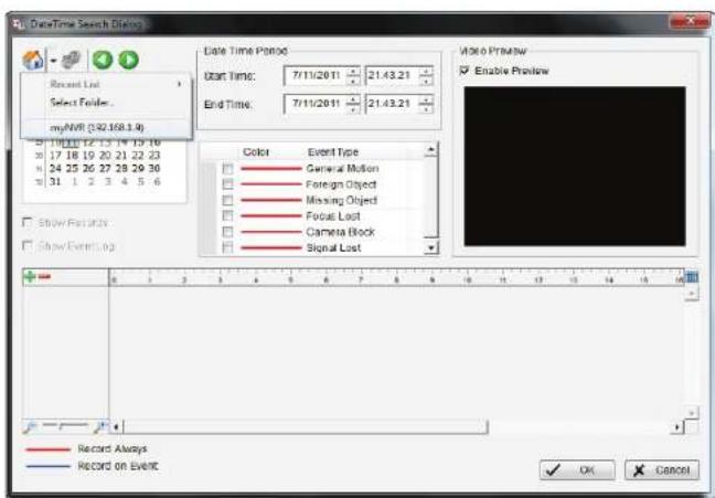
Click the Open Record button to access the Date-Time Panel and select the video records which you would like to review. Users can refresh the Date Time Search Dialog Window or go to the previous or next recording date by pressing the upper left corner buttons.
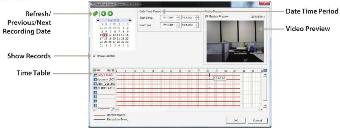
Record Display Window: Display the available recorded video records.
Date Time Period: Select the start and end points that indicate the time period you would like to view. Note: The time period cannot exceed two days.
Video Preview: Check the Enable Preview option to view the selected video.
Time Table (pre-set Click the + icon to select all channels, or click the - icon to deselect all channels. The scale bar can be used to recording schedule): modify the scale of the timetable. There are two recording modes: Record Always and Record on Event. The timetable will display these two modes in different colors.
Show Records: Displays the recording data in a timetable.
Step 1: From the Record Display Window at the top left of the Date Time Panel, select the date you would like to search the record from. The red lines shown on the timetable indicate available recorded video records.
Step 2: Use color bars to differentiate recording types from each other. This will help you select video clips.
Step 3: Highlight the video clip you would like to review by left-clicking and dragging the time period. You may also utilize the Start Time and End Time in the Date Time Period Section after choosing the camera. The scale of the timetable can be modified using the icon at the bottom left corner.
Step 4: Select the Enable Preview option to get the preview of the video you select.
Step 5: Click the camera name to select the cameras you would like to play back.
Step 6: Click the OK button to begin playback.
Note:
The Record Display Window can be shown in (a) calendar view or (b) list control view. To modify the settings of the record display window, click the Setting button at the right of the page.
Recorded Video Enhancement
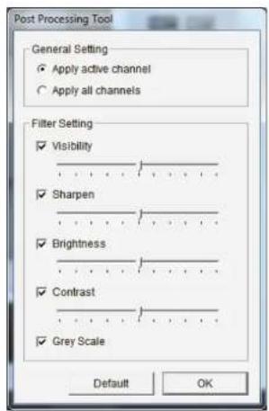
During playback, users can click the Enhancement button to enable post processing of the selected video.
General Setting
Apply active channel: The settings will only be applied to the selected channel.
Apply all The settings will only be applied to those currently shown on the screen. channels:
Filter Setting
Visibility: Select this option and adjust the gamma to change the luminance.
Sharpen: Select this option to activate the function. Move the slider control to the right to sharpen the image, to the left to soften it.
Brightness: Select this option and move the slider control to the right or left to make the image brighter or dimmer.
Contrast: Select this option and move the slider control to the right or left to increase or decrease the contrast.
Greyscale:
Default: Select this option to display the image in black and white.
OK: Reset settings to their defaults.
Apply the modifications.
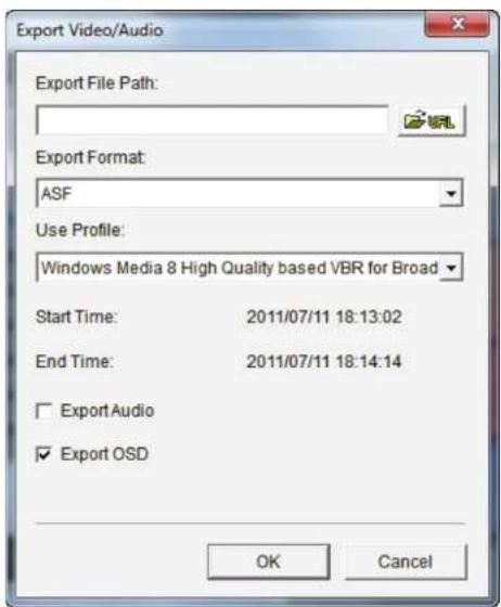
Save Video
Step 1: During playback, users can choose the camera where they would like to save a video clip.
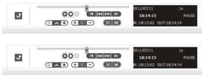
Step 2: Set the cue in and cue out points; the cue in and cue out time will be shown on the information window.
Then click Save Video.
Step 3: Choose the folder where you would like to save the file.
Step 4: Input the file name and click Save.
Step 5: Choose the export format.
Step 6: Choose the user profile.
Step 7: Select the Export Audio option if the video has audio and you would like to export with the video.
Step 8: Click OK.
Note:
The .asf format is recommended for exporting video.
Save Image
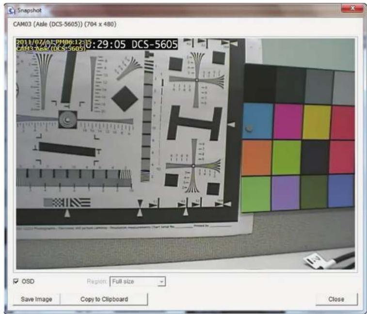
Step 1: During playback, users can choose to save an image from a selected camera.
Step 2: Click Save Image when the desired image is shown on the screen.
Step 3: Click Save Image again to choose the folder where you would like to save the file to.
Step 4: Choose the desired image format (BMP or JPEG).
Step 5: Input the file name.
Step 6: Click Save.
Note:
You may skip step 3 by pre-selecting a folder and format for images. See the Setting option for more details.
Print Image
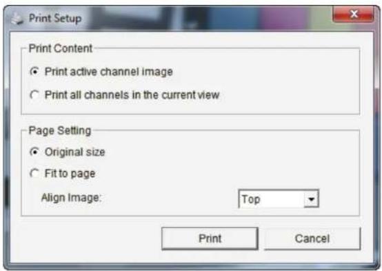
Step 1: During playback, you can choose to print a selected image.
Step 2: Click Print when the desired image is shown on the screen.
Step 3: Select your desired print settings.
Page Setting
Print Content: Print the image from currently selected channel or all the channels shown on the screen.
Print in Select this option to have the image print in original size. original size:
Fit the page: Select this option to fit the image to the page.
Align Image: Align the top, center or bottom.
Step 4: Click Print.
Back up the Recorded Video
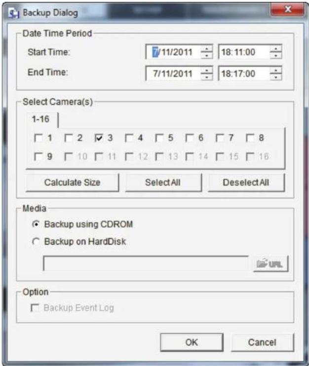
Unlike the Save Video function, the Backup function will save all the recorded videos during the time period you select, instead of a single video clip.
Step 1: Use Open Record to select the desired data.
Step 2: Click Backup.
Step 3: Set the Start Time and End Time that you would like to back up data.
Step 4: Select the cameras that you would like to back up.
Step 5: Select the directory where you would like to back up the data to.
Step 6: Click Backup.
The system will then begin the backup process automatically.
Playback Manager Application
Step 1: Please insert the product CD.
Step 2: Install the Playback application from CD.
Step 3: Run the Playback application from the Start -> Programs -> D-Link -> Playback Manager.
The Playback System control panel is similar to the playback panel in Internet Explorer. See the Playback section for more details about those buttons.
1/4/9/16 Split Users can select to view a single camera or 4 Screen: cameras at a time. DNR-322L only supports 1 camera playback.
Full Screen: Select to display the video with full screen. Press the ESC button on the keyboard to return to normal display.
Information Display video date and time, cue in/out points, time Window: and speed.
Audio Volume Adjust the sound level. Control :
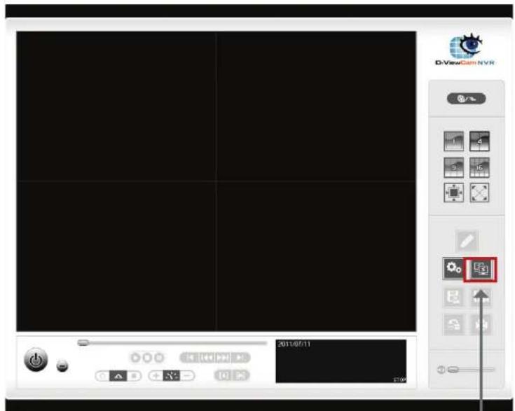
Remote Server
Digital Zoom: Click the icon to digital zoom in or digital zoom out the view. Every camera can use this function.
Play/Stop/ Select a camera/video and click this button to play/stop/pause a particular channel. Pause:
Speed: Click the + or - button to increase or decrease the playback speed.
Cue in/Cue Click the Cue In or Cue Out button to set the time period for Save Video. out:
Step forward/ Click to pause the playback and move to next frame or last frame. Reverse:
Fast forward/ Click to pause the playback and move to next minute or last minute. Reverse:
Set Connections to the Units
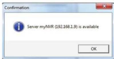
Step 1: Click Remote Server.
Step 2: Input the name of your unit.
Step 3: Input the IP address of that unit.
Step 4: Modify the port if necessary.
Step 5: Input the user name.
Step 6: Input the password.
Step 7: Check the Save Password option.
Step 8: Click Test Server to test the connection between the local application and the remote unit.
Step 9: Click Add to add this unit into the remote server list. Step 10: Click OK.
The Search, Playback, Video Enhancement, Print Image, Save Video, Save Image, and Backup functions are the same as the steps in Internet Explorer. Please see the preceding sections: Search the Recording Video to Playback, Recorded Video Enhancement, Save Video, Save Image, Print Image, and Back up the Recorded Video.
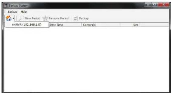
Backup System
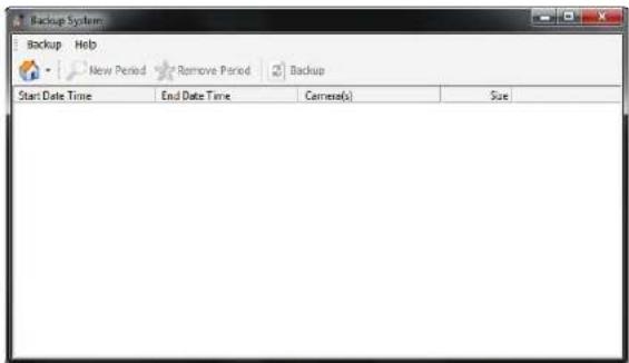
In addition to the ways mentioned in the previous chapters, you can apply the application to back up your files.
Run the Backup application from the Start -> Programs -> D-Link -> Backup System
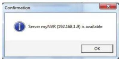
Step 1: Input the IP address of your unit.
Step 2: Input the user name.
Step 3: Input the password.
Step 4: Click OK.
Step 5: Click New Period.
Step 6: Select the record date.
Step 7: Set the Start Time and End Time you would like to back up (or highlight the video records that you would like to back up).
Note: The time period cannot exceed 24 hours.
Step 8: Select the cameras you would like to back up.
Step 9: Click OK.
Step 10: Select the time slot which you would like to back up.
Section 7 - Playback Manager Application
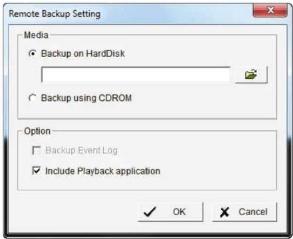
Step 11: Click Backup.
Step 12: Select the location where you would like to save the backup data.
Step 13: Check the Include Playback application option, which will add Playback application into the backup folder.
Step 14: Click OK.
![Date/Time Search Dialog [my/NVR] July 2015 5 M T W T F S 26 27 28 29 30 1 2 3 4 5 6 7 8 9 10 11 12 13 14 15 16 17 18 19 20 21 22 23 24 25 26 27 28 29 30 32 1 2 3 4 5 6 Show Records Video Preview Start Time: 7/11/2011 18:11:00 End Time: 7/11/2011 18:11:50 Enable Preview 2011/07/11 Record Alerts Record on Event Record Alerts Record on Event 07/11 baby's room Overway (DCS) Airx (DCS-500) ZF (DCS-6113) Record Alerts Record on Event OK Cancel](/content/2026/05/1028541/images/12c6a7ae88ed9ddad7d98113df6dc63e477df8b637789e62bf412034775b598f.jpg)
Verification Tool
The Verification Tool verifies whether the data created by the system has been tampered with. It's the process by which a digital watermark (a digital signature) is added to each recorded video frame to ensure its authenticity.
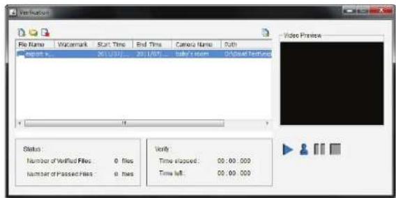
There are two types of data that could be verified by Verification Tool:
- File in (.avi) (.asf).
- File in (.bmp) (.jpg).
Add File: Add a single file to the list for verification.
Add Folder: Choose a folder with multiple files to list for verification.
Remove File: Remove indicated file(s) from list.
Select All: Select all files in the list for verification.
Note:
Choose the file type first before selecting files.
Verify Image/Video
-
Select single or multiple files for verification.
-
Click Verify 📁 to start verification.
-
The verification result will show on the watermark column. If a file was tampered with, it will show ✗; if a file passed verification, it will show √.
Troubleshooting
Check the System Status LED
The system status LED reports the condition of the enclosure fan and power supply:
Solid Blue: NVR is functioning normally
Blinking Blue: NVR is shutting down
If your unit is configured to work with a UPS, it will continue to run for a while after a power supply failure.
Check Disk Status LEDs
The disk status LEDs report the condition of the disk drives:
These lights will be solid BLUE when drives are connected but inactive.
The lights will blink when the drives are being accessed, formatted, or synchronized.
They will illuminate AMBER if a drive has failed.
Replace a Failed Disk Drive
If a disk drive fails, the Disk Status LED will turn amber. If the disk drive belongs to a RAID Volume, the Volume will go Critical or Offline.
Replace the failed disk drive with a new disk drive of the same or slightly greater capacity.
Please make sure you have powered down the unit, then take the following steps:
Step 1: Open the unit's front cover.
Step 2: Pull out the failed disk drive.
Step 3: Install a new disk drive into the slot.
If the failed drive belonged to a RAID Volume, the RAID Volume will begin rebuilding as soon as the new drive is installed. During the rebuild, the Disk Status LED will blink. If the replacement drive is free, i.e. not assigned to a RAID Volume or as a spare, the Disk Status LED remains dark after you install the new drive.
Check RAID Volume Status
Click the Status -> Device Info tab from the menu.
Respond to a Critical RAID Volume
How the unit responds to a critical RAID Volume depends on the RAID level of your Volume and whether you have a spare drive available:
For RAID 1 Volumes, if a spare drive is available, the RAID Volume will begin rebuilding itself automatically.
For RAID 1 Volumes, when no spare drive is available, you must replace the failed disk drive. The RAID Volume will begin rebuilding itself when you install the new disk drive.
RAID 0 Volumes go offline after a disk drive failure. A RAID 0 volume cannot be rebuilt. All data on the volume will be lost.
Restore the Default Administrator's Password
If you forget the password, you can reset the password for admin to the default password:
Caution
When you reset or recover your unit, sometimes it will cause data corruption. Back up your recorded data before resetting your unit.
Install ActiveX
If you cannot see the complete page of the system when using Internet Explorer, the ActiveX installation process may not be complete.
Step 1: Click Live View/Playback on the top right.
Step 2: The browser will ask whether to install ActiveX.
Step 3: Click the upper bar to begin the installation process.
Step 4: Click Install to complete the process.
Cannot Log in to the Unit through Internet Explorer
-
Check the settings of your anti-virus software.
-
Adjust the settings of or disable your anti-virus software.
Choose a RAID Level
There are several issues to consider when choosing the RAID level. The following summarizes some advantages, disadvantages, and applications for each choice.
RAID 0
Advantages
- Implements a striped disk RAID Volume as the data is broken down into blocks and each block is written to a separate disk drive
- I/O performance is greatly improved by spreading the I/O load across many channels and drives
- No parity calculation overhead is involved
Disadvantages
- Not a true RAID because it is not fault tolerant
- The failure of just one drive will result in all data in a RAID Volume being lost
- Should not be used in mission critical environments
RAID 1
Advantages
- Simplest RAID storage subsystem design
- Can increase read performance by processing data requests in parallel since the same data resides on two different drives
Disadvantage
- Very high disk overhead - uses only 50% of total capacity
Replacing or Adding a New Hard Drive
It is recommended that you back up your important files before replacing or adding a new hard drive to the NVR.
Replacing a Hard Drive:
Please make sure the power is off before replacing a hard drive. After you have installed the new drive, turn on the NVR and then connect to the Web UI. The NVR will prompt you to format the new drive (Standard, RAID 1 mode) or both drives (JBOD, RAID 0 mode).
Adding a New Hard Drive:
The NVR is able to work with one single hard drive under Standard mode. Please make sure the power is off before installing a second hard drive.
After you have installed the new drive, turn on the NVR and then connect to the Web UI. The NVR will prompt you to format the new drive.
Note: Formatting a hard drive will erase the data stored on the hard drive. Please back up important data before formatting a hard drive.
Technical Specifications
Firmware Specifications
OS
+ Linux
CAMERAS SUPPORT
+ Supports all D-Link network cameras. Includes support for auto-discovery and up to 3 megapixel resolution.
Max. capacity (NVR mode only):
- H.264 1080P (bitrate): 90 Mbps
- H.264 720P (bitrate): 90 Mbps
- MJPEG 1080P (frame rate): 90 fps
- MJPEG 720P (frame rate): 192 fps
Max. capacity (NVR+File Server mode):
- H.264 1080P (bitrate): 68 Mbps
- H.264 720P (bitrate): 68 Mbps
- MJPEG 1080P (frame rate): 70 fps
- MJPEG 720P (frame rate): 150 fps
Note: To enable the File Server function will affect the recording performance. It also differs by video compression.
CAMERA SEARCH
+ UPnP
+ Synchronized audio & video recording.
COMPRESSION FORMAT
+ H.264, MPEG-4, M-JPEG (depend on the Network Cameras)
VIDEO SETTING
+ Resolution, quality, frame rate, enable audio, go to camera interface
RECORDING TYPE
+ Record by schedule, manual record and event recording (motion detection from camera)
REMOTE LIVE VIEW
- Supported via IE browser (Max. 9 simultaneous channels)
- Supports mydlink portal via IE or other browsers (Max. 1 simultaneous channel)
REMOTE LIVE VIEW CONTROL
+ Live view, preset/go, patrol, focus, PTZ functions, snapshot, full screen, digital zoom, e-map, multiple view(1/4/6/9/16/25/36/48) with duplicated camer
REMOTE PLAYBACK
- Supported via IE and NVR client
- Playback system with timeline GUI, search by event, area, cameras, date and time
- IE & NVR client support 1 channel playback
- Digital zoom in to specific area
REMOTE PLAYBACK CONTROL
+ Playback with normal, fast forward/rewind, and step forward/rewind
OVERWRITE RECORDING
+ Auto recycling when disk storage is full
FILE EXPORT
- Export videos to AVI or ASF file
- Export images to BMP or JPG file
USER ACCOUNT
+ Additional accounts can be created to allow user access to the system, and specify authorization for the camera channels, PTZ, etc.
DDNS
+ D-Link DDNS server support
SYSTEM TIME
+ Set the system time (D-Link NTP, Input time, Sync with computer)
REMOTE BACKUP
- Remote software can back up raw data to redundant storage
- Auto back up video from the previous day to the FTP server
SYSTEM STATUS
- Camera status, System status
- Still picture EMAP support
NETWORK SERVICE PROTOCOLS
- IPV4, ARP, TCP, UDP, ICMP
- DHCP Client
- NTP Client (D-Link)
- DNS Client
- DDNS Client (D-Link)
- SMTP Client
- HTTP Server
- PPPoE
- UPnP
- IP filtering
USER INTERFACE
- mydlink web portal - Internet Explorer 7 or later
- HTTP Web browser - Internet Explorer 7 or later (32 bit OS only)
- NVR Search Utility
Hardware Specifications
STANDARDS
- IEEE 802.3/u/z
- Auto MDI/MDI-X
- SATA I, II
HARD DISK ^1
- Hard Disk control & manage via PC
+Reformat Disk - RAID 0
- RAID 1 ^2
+JBOD
TWO RESET MODES
- Reset firmware GUI button
- HW reset button (press over 5 seconds)
FLASH ROM
+ 128 MB
RAM
+ 256 MB DDR II
NIC
+ Gigabit Ethernet LAN port (10/100/1000 Mbps)
I/O PORTS
+ RJ45 port
+ DC-in jack
+ USB port for UPS status update (optional)
POWER ADAPTER
+ DC 12 V/3 A
RESET BUTTON
+ Reset to factory default
SECURITY
+ Device lock hole
POWER CONSUMPTION
- Max. power consumption: 25.20 W
- Standby state max. power consumption: 0.23 W
DIMENSIONS (W x D x H)
+ 115 (W) x 146.4 (D) x 178.5 (H) mm (4.53 x 5.76 x 7.03 inches)
WEIGHT
+ 875.1 g (1.93 lbs)
- Operating: 0° to 55° C (32° to 131° F)
- Storage: -20" to 70" C (-4" to 158" F)
HUMIDITY
+ Operating: 5% to 90% (non-condensing)
PACKAGE CONTENTS
+ 2-Bay NVR
+ Power Adapter
+ Ethernet Cable
+ Quick Installation Guide
+ Power Cable Holder
+ CD-ROM with:
- Software
- Product Documentation
^1 An external SATA drive is required to store or share files. (Not included.)
^3 RAID1 mirroring requires the use of two internal SATA drives. To avoid data incompatibility in RAID 1 operation, use identical SATA drives from the same manufacturer. Formatted drive capacity for RAID 1 operation is dependant on the drive capacity of the lowest-sized drive. Some older generation SATA drives may not be compatible. For a list of SATA drives that have been tested to work with the NVR, visit the D-Link support web site.
- User Manual
- 2-Bay Professional Network Video Recorder (NVR)
- Manual Overview
- Trademarks
- Power Usage
- Table of Contents
- Package Contents
- System Requirements
- Introduction
- Features
- Comprehensive IP Surveillance Solution
- Complete Network Functionality
- Fully Functional Recording
- Comprehensive Data and Hardware Security
- Powerful Event Management
- Instant Live View
- Intelligent Playback
- Getting Started NVR Software CD
- D-Link
- Welcome
- Setup Wizard
- Windows
- Install the Hard Drives
- Section 3 - Installation
- Power and Device Selection
- Admin password
- HDD Configuration and Drive Mapping
- Note:
- Search for Cameras
- Management Options
- Set up Internet connection
- Setup Wizard Mac
- HDD Configuration
- mydlink Portal
- NVR Status
- Live Video
- Playback
- Status
- NVR Info
- Configuration D-Link NVR Search Utility Windows
- D-Link NVR Search Utility Mac
- Web UI Login
- Configure Hard Drive
- Auto Search Camera
- Web UI
- Configuring the NVR
- BASIC OPERATION
- ADVANCED OPERATION
- Network Setup
- Static IP:
- IP Address:
- Subnet Mask:
- Gateway IP
- Settings:
- Camera Search
- Note
- Camera Setup
- Audio and Video
- Step 3: Click Save Settings.
- 2nd Stream Settings
- Live and Playback Setup
- Live Streaming Server
- Playback Server
- Recording Schedule
- Set Recording Mode
- Set Recording Schedule
- Set Recording Schedule Configuration
- Auto Backup
- Event Setup
- Backup Server
- E-mail Setup
- Add Contacts
- Time and Date Setup
- Maintenance User Management
- Add New User
- User List
- Change User's Password
- Delete A User
- System
- RAID
- What is RAID?
- Dynamic DNS
- Firmware Update
- Camera Status
- System Info
- System Log
- NVR Log
- Support
- Set up Live View
- General Setting
- General
- Camera Setting
- OSD (On-screen display) Setting
- Monitor Display Setting
- Notification
- Set up Joystick Control
- Multiple view
- Play the Recorded Video
- Open Record and Setting
- Record Display
- Play
- Capture Image
- Miscellaneous
- Search the Recorded Video to Playback
- Recorded Video Enhancement
- Filter Setting
- Save Video
- Save Image
- Print Image
- Page Setting
- Back up the Recorded Video
- Playback Manager Application
- Set Connections to the Units
- Backup System
- Section 7 - Playback Manager Application
- Verification Tool
- Verify Image/Video
- Troubleshooting
- Check the System Status LED
- Check Disk Status LEDs
- Replace a Failed Disk Drive
- Check RAID Volume Status
- Respond to a Critical RAID Volume
- Restore the Default Administrator's Password
- Caution
- Install ActiveX
- Cannot Log in to the Unit through Internet Explorer
- Choose a RAID Level
- RAID 0
- Advantages
- Disadvantages
- RAID 1
- Disadvantage
- Replacing or Adding a New Hard Drive
- Replacing a Hard Drive:
- Adding a New Hard Drive:
- Technical Specifications
- Firmware Specifications
- CAMERAS SUPPORT
- COMPRESSION FORMAT
- VIDEO SETTING
- RECORDING TYPE
- REMOTE LIVE VIEW
- REMOTE LIVE VIEW CONTROL
- REMOTE PLAYBACK
- REMOTE PLAYBACK CONTROL
- OVERWRITE RECORDING
- FILE EXPORT
- USER ACCOUNT
- DDNS
- SYSTEM TIME
- REMOTE BACKUP
- SYSTEM STATUS
- NETWORK SERVICE PROTOCOLS
- USER INTERFACE
- Hardware Specifications
- STANDARDS
- HARD DISK 1
- TWO RESET MODES
- FLASH ROM
- RAM
- NIC
- I/O PORTS
- POWER ADAPTER
- RESET BUTTON
- SECURITY
- POWER CONSUMPTION
- DIMENSIONS (W x D x H)
- WEIGHT
- HUMIDITY
Brand : D-LINK
Model : DNR-322L
Category : Server