ZS5300 - Receiver MARANTZ - Free user manual and instructions
Find the device manual for free ZS5300 MARANTZ in PDF.

User questions about ZS5300 MARANTZ
0 question about this device. Answer the ones you know or ask your own.
Ask a new question about this device
Download the instructions for your Receiver in PDF format for free! Find your manual ZS5300 - MARANTZ and take your electronic device back in hand. On this page are published all the documents necessary for the use of your device. ZS5300 by MARANTZ.
USER MANUAL ZS5300 MARANTZ
The lightning flash with arrowhead symbol within an equilateral triangle is intended to alert the user to the presence of uninsulated “dangerous voltage” within the product's enclosure that may be of sufficient magnitude to constitute a risk of electric shock to persons.

The exclamation point within an equilateral triangle is intended to alert the user to the presence of important operating and maintenance (servicing) instructions in the literature accompanying the product.
WARNING
TO REDUCE THE RISK OF FIRE OR ELECTRIC SHOCK, DO NOT EXPOSE THIS PRODUCT TO RAIN OR MOISTURE.
CAUTION: TO PREVENT ELECTRIC SHOCK, MATCH WIDE BLADE OF PLUG TO WIDE SLOT, FULLY INSERT.
ATTENTION: POUR ÉVITER LES CHOC ÉLECTRIQUES, INTRODUIRE LA LAME LA PLUS LARGE DE LA FICHE DANS LA BORNE CORRESPONDANTE DE LA PRISE ET POUSSER JUSQU'AU FOND.
NOTE TO CATV SYSTEM INSTALLER:
This reminder is provided to call the CATV (Cable-TV) system installer's attention to Section 820-40 of the NEC which provides guidelines for proper grounding and, in particular, specifies that the cable ground shall be connected to the grounding system of the building, as close to the point of cable entry as practical.
IMPORTANT SAFETY INSTRUCTIONS
READ BEFORE OPERATING EQUIPMENT
This product was designed and manufactured to meet strict quality and safety standards. There are, however, some installation and operation precautions which you should be particularly aware of.
-
Read Instructions – All the safety and operating instructions should be read before the product is operated.
-
Retain Instructions – The safety and operating instructions should be retained for future reference.
-
Heed Warnings – All warnings on the product and in the operating instructions should be adhered to.
-
Follow Instructions – All operating and use instructions should be followed.
-
Cleaning – Unplug this product from the wall outlet before cleaning. Do not use liquid cleaners or aerosol cleaners. Use a damp cloth for cleaning.
-
Attachments – Do not use attachments not recommended by the product manufacturer as they may cause hazards.
-
Water and Moisture – Do not use this product near water-for example, near a bath tub, wash bowl, kitchen sink, or laundry tub, in a wet basement, or near a swimming pool, and the like.
-
Accessories – Do not place this product on an unstable cart, stand, tripod, bracket, or table. The product may fall, causing serious injury to a child or adult, and serious damage to the product. Use only with a cart, stand, tripod, bracket, or table recommended by the manufacturer, or sold with the product. Any mounting of the product should follow the manufacturer's instructions, and should use a mounting accessory recommended by the manufacturer.
-
A product and cart combination should be moved with care. Quick stops, excessive force, and uneven surfaces may cause the product and cart combination to overturn.

-
Ventilation – Slots and openings in the cabinet are provided for ventilation and to ensure reliable operation of the product and to protect it from overheating, and these openings must not be blocked or covered. The openings should never be blocked by placing the product on a bed, sofa, rug, or other similar surface. This product should not be placed in a built-in installation such as a bookcase or rack unless proper ventilation is provided or the manufacturer's instructions have been adhered to.
-
Power Sources – This product should be operated only from the type of power source indicated on the marking label. If you are not sure of the type of power supply to your home, consult your product dealer or local power company. For products intended to operate from battery power, or other sources, refer to the operating instructions.
-
Grounding or Polarization – This product may be equipped with a polarized alternating-current line plug (a plug having one blade wider than the other). This plug will fit into the power outlet only one way. This is a safety feature. If you are unable to insert the plug fully into the outlet, try reversing the plug. If the plug should still fail to fit, contact your electrician to replace your obsolete outlet. Do not defeat the safety purpose of the polarized plug.
-
Power-Cord Protection – Power-supply cords should be routed so that they are not likely to be walked on or pinched by items placed upon or against them, paying particular attention to cords at plugs, convenience receptacles, and the point where they exit from the product.
- Protective Attachment Plug – The product is equipped with an attachment plug having overload protection. This is a safety feature. See Instruction Manual for replacement or resetting of protective device. If replacement of the plug is required, be sure the service technician has used a replacement plug specified by the manufacturer that has the same overload protection as the original plug.
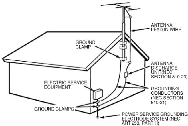
- Outdoor Antenna Grounding – If an outside antenna or cable system is connected to the product, be sure the antenna or cable system is grounded so as to provide some protection against voltage surges and built-up static charges. Article 810 of the National Electrical Code, ANSI/NFPA 70, provides information with regard to proper grounding of the mast and supporting structure, grounding of the lead-in wire to an antenna discharge unit, size of grounding conductors, location of antenna-discharge unit, connection to grounding electrodes, and requirements for the grounding electrode. See Figure 1.
Figure 1
EXAMPLE OF ANTENNA GROUNDING AS PER
NATIONAL ELECTRICAL CODE, ANSI/NFPA 70
text_image
ANTENNA LEAD IN WIRE GROUND CLAMP ANTENNA DISCHARGE UNIT(NEC SECTION 810-20) ELECTRIC SERVICE EQUIPMENT GROUNDING CONDUCTORS (NEC SECTION 810-21) GROUND CLAMPS POWER SERVICE GROUNDING ELECTRODE SYSTEM (NEC ART 250, PART H)natural_image
Line drawing of an electrical outlet with three leads (no text or symbols)-
Lightning – For added protection for this product during a lightning storm, or when it is left unattended and unused for long periods of time, unplug it from the wall outlet and disconnect the antenna or cable system. This will prevent damage to the product due to lightning and power-line surges.
-
Power Lines - An outside antenna system should not be located in the vicinity of overhead power lines or other electric light or power circuits, or where it can fall into such power lines or circuits. When installing an outside antenna system, extreme care should be taken to keep from touching such power lines or circuits as contact with them might be fatal.
-
Overloading – Do not overload wall outlets, extension cords, or integral convenience receptacles as this can result in a risk of fire or electric shock.
19.Object and Liquid Entry – Never push objects of any kind into this product through openings as they may touch dangerous voltage points or short-out parts that could result in a fire or electric shock. Never spill liquid of any kind on the product.
-
Servicing – Do not attempt to service this product yourself as opening or removing covers may expose you to dangerous voltage or other hazards. Refer all servicing to qualified service personnel.
-
Damage Requiring Service – Unplug this product from the wall outlet and refer servicing to qualified service personnel under the following conditions:
a. When the power-supply cord or plug is damaged.
b. If liquid has been spilled, or objects have fallen into the product.
c. If the product has been exposed to rain or water.
d. If the product does not operate normally by following the operating instructions. Adjust only those controls that are covered by the operating instructions as an improper adjustment of other controls may result in damage and will often require extensive work by a qualified technician to restore the product to its normal operation.
e. If the product has been dropped or damaged in any way, and
f. When the product exhibits a distinct change in performance – this indicates a need for service.
-
Replacement Parts – When replacement parts are required, be sure the service technician has used replacement parts specified by the manufacturer or have the same characteristics as the original part. Unauthorized substitutions may result in fire, electric shock, or other hazards.
-
Safety Check – Upon completion of any service or repairs to this product, ask the service technician to perform safety checks to determine that the product is in proper operating condition.
-
Wall or Ceiling Mounting – The product should be mounted to a wall or ceiling only as recommended by the manufacturer.
-
Heat - The product should be situated away from heat sources such as radiators, heat registers, stoves, or other products (including amplifiers) that produce heat.
-
Apparatus shall not be exposed to dripping and splashing and no objects filled with liquids, such as vases, shall be placed on the apparatus.
Table of Contents
Introduction......2
Features ......2
About the keypad ....3
Accessories ....3
Functional Overview ......4
Front panel 4
Rear panel....5
Remote control unit (RC5300ZS)....6
ID Code Setup......8
Preparation and Connection .....9
Connecting speakers 9
Connection example ....10
Operation Examples....15
Remote Code List ....16
Troubleshooting ....17
Care and Maintenance ....17
Specification 18
FeaturesIntroduction
Thank you for purchasing the Marantz ZS5300 Multi Zone Selector Amplifier.
This remarkable component has been engineered to provide you with many years of whole house audio enjoyment.
Please take a few minutes to read this manual thoroughly before you connect and operate the ZS5300.
As there are a number of connection and configurations options, you are encouraged to discuss your own particular multi zone setup with your Marantz A/V specialist dealer.
ZS5300 is a 2ch x 3 zones amplifier with Multi-Zone/Source selector.
- All channels identically designed, complete discrete construction class-D power amplifier.
To maximize sound performance, a large R-core power transformer is used.
The power amplifier is designed using discrete, class-D amplifier construction for all 6 channels. This assures that the channels are the same quality and power.
• 3 zone control function
Combining this unit and a keypad, you can construct a multi-zone system which can control up to 3 zones.
- ID selector switch which allows for zone expansion
This unit can be connected in cascade by changing the ID switch on the rear panel. Up to 3 units can be connected so the zone system can be expanded up to 9 zones.
• Power save function by independent power control
This unit can control the power on/off for each zone. The power for the un-used zone can be turned off for power saving capability.
- Party mode
You can direct the same source to all the zones simultaneously. This is terrific for events like entertaining. In addition you can control volume and muting capability.
- Banana plug compatible speaker terminal
The speaker terminals can be connected with banana plugs directly as well as traditional speaker cable.
About the keypad
You can connect the majority of keypads, IR receivers as well as some control related products available in the market.
These are examples of systems that have been tested by Marantz America:
NILES
Keypad : IntelliPad
IR Main System unit : IRP6+
IR Sensor : MS 2
IR Flasher : IRC-2

NILES®
The Niles logo and IntelliPad are registered trademark of Niles Audio Corporation.
XANTECH
Keypad: SMARTPAD3
Connecting block : 789-44
IR Sensor : 480-30 Series
IR Emitter : 282M
xantech.
The Xantech logo and SMARTPAD3 are registered trademark of Xantech Corporation.
Note:
If you wish to use products that are not listed above, please contact your authorized Marantz dealer for possible compatibility issues.
Accessories
- AC power cord x 1

natural_image
Line drawing of a cord with two connectors and a connector plug (no text or symbols)- Remote control unit x 1

text_image
Diagram of a remote control with labeled buttons and function keys on the right side- AA-size batteries x 2

natural_image
Two cylindrical batteries shown in a row, no text or symbols presentFunctional Overview
Front panel

text_image
⑥ ① ② ③ ④ ⑤ ⑥ ZONE 1 ZONE 2 ZONE 3① Main power switch (POWER ON / STANDBY)
Press this button to turn the main power on. Press again to turn it off. When the main power is turned on, Zone1, Zone2 and Zone3 turn into standby mode and power for each zone can be switched with the remote control unit RC5300ZS (provided) or a Keypad (option). For regular use, please leave the unit powered on.
②Volume level indicator (LEVEL)
These indicators show the level of the volume. When all the indicators light up, the volume is at the maximum level. When all the indicators lights are off, the volume is at the minimum level. Volume can be adjusted individually from each of Zone1, Zone2 and Zone3. Volume adjustment can be adjusted, with the remote control unit or a Keypad.
Mute indicator (MUTE)
These indicators flash when the sound is muted. When volume is at the maximum, all the indicators flash. When the volume is at the minimum, only the first indicator flashes. Mute can be controlled individually from each of Zone1, Zone2 and Zone3. Muting can be done with the remote control unit or a Keypad. If the volume is adjusted when muted, mute is released.
Caution
When these indicators are flashing, no sound is outputted. When releasing mute, please check the volume position. If volume is set too loud, the speakers may be damaged.
③ Standby indicator (STANDBY)
This indicator lights up when any of the zones are in standby. Zone1, Zone2 and Zone3 can be in standby mode independently. Power for each zone can be controlled with the remote control unit or a Keypad.
④ Direct indicator (DIRECT)
When the "Zone Direct" input is chosen for the source, this indicator lights up. The source connected to the "Zone Direct" terminal for Zone1 can be selected only for Zone1. The same applies for Zone2 and Zone3. Source selection can be selected with the remote control unit or a Keypad.
⑤Input indicator (INPUT)
Depending on which input is selected in each zone, the appropriate INPUT indicator will be illuminated. The Inputs can be selected by a remote control unit or a Keypad.
⑥IR (Remote control) sensor
This window receives infrared signals from the remote control unit.

text_image
1 2 3 4 5 6 AUDIO IN AUDIO OUT ZONE DIRECT IN ZONE 3 PRE OUT STATUS OUT ZONE 1 ZONE 3 FLASHER IN REMOTE CONTROL ID SELECTOR 1.2.3 SPEAKERS (MINIMUM 5 CHMS) ZONE 1 ZONE 2 ZONE 3 MARANTZ MODEL NO. ZENXOR VOLTAGE SELECTOR 115V 230V AC IN 7 8 9 10 11 12 SETRIAL NO. + - - -1 Audio input terminal (AUDIO IN)
Connect the analog audio output from your audio device (CD player, TV, DVD player, etc.). Up to 3 audio devices can be connected.
2 Audio output terminal (AUDIO OUT)
These terminals are designed as an Audio pass through. They can be used to when cascading one or two other ZS5300s. Another example might be to share source components with a dedicated home theater system etc.
3 Zone direct input terminal (ZONE DIRECT IN)
These terminals are only for their corresponding zone. Connect the analog audio output terminals from your audio device (CD player, TV, DVD player, etc.). Although up to 3 devices can be connected each to a different zone, the device connected to "ZONE DIRECT 1" can be played only in ZONE 1. The same applies to ZONE DIRECT 2 and ZONE DIRECT 3.
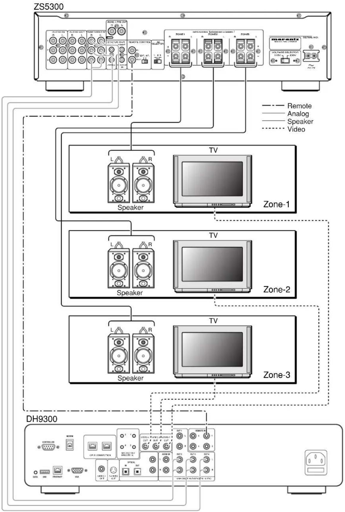
- You can construct a powerful & unique multi-zone system by connecting the Marantz music server (DH9300). (P. 13)
4 Zone 3 pre output terminal (ZONE 3 PRE OUT)
These terminals are preamplifier output terminals for Zone 3. These terminals can be connected with other audio devices such as an external amplifier.
5 Remote control input / output terminal (REMOTE CONTROL)
By connecting this unit to another Marantz audio component using a System control cable, you can remotely operate the components as a single system.
6 Speaker output terminal (SPEAKERS)
Connect speakers for each zone.
• Rating of speaker impedance: 6 ohm
7 Status output terminal (STATUS OUT)
These terminals are DC trigger output terminals to determine whether power of a zone is on or off. Connect these terminals to Keypads, etc.
• Rating of status output: 12V 100mA.
8 Flasher input terminal (FLASHER IN)
This terminal is to control the unit from each zone. Connect the control signal from a Keypad, etc.
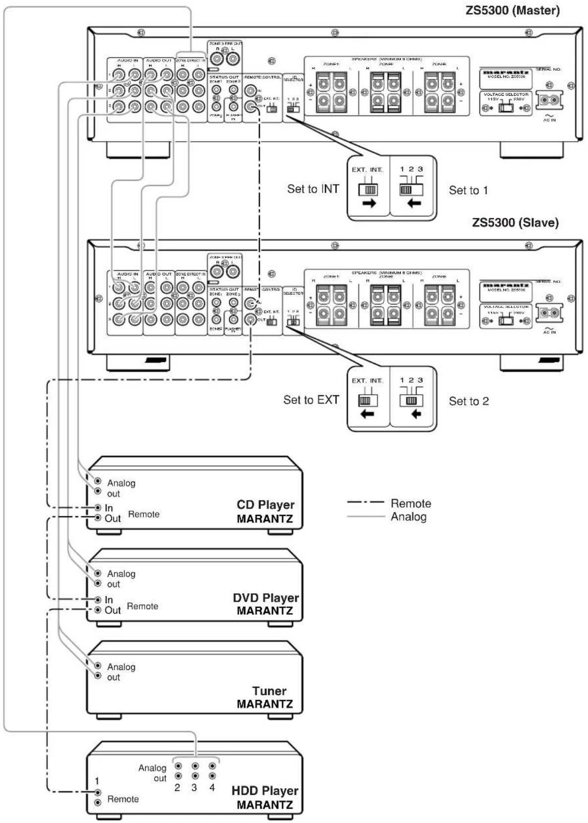
9 Remote control internal / external switch (INT. / EXT.)
This switch is to select if the remote sensor on the front panel work or not. If you use two or more ZS5300s in cascade connection, set this switch at INT. for the ZS5300 that functions as the maser. Set the switch at EXT. for the slave ZS5300s.
INT.: Enable the remote sensor.
EXT.: Disable the remote sensor.
1 ID select switch (ID SELECTOR)
When two or three ZS5300s are used, set independent ID numbers for each. Up to 3 ZS5300s can be connected. Different ID numbers must be set for each unit.
1 Voltage selector (VOLTAGE SELECTOR)
Select the power voltage of your location. You can select 115V or 230V.
- Be sure to disconnect the power cord when changing this switch.
1 Power inlet (AC IN)
Plug the power cord into this socket.
CAUTION:
Be sure to use the power cord rating more than 2.5A, 250V and 18AWG when operating 230V AC voltage.
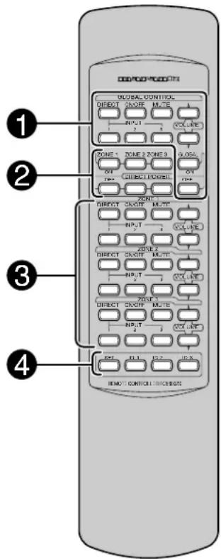
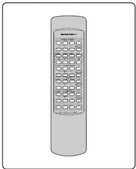
Remote control unit (RC5300ZS)
text_image
GLOBAL CONTROL DIRECT GOUR MUTE INPUT VOLT-RE ZONE 1 ZONE 2 ZONE 3 ON DIRECTOR ON ZONE 1 DIRECT GOUR MUTE INPUT VOLT-RE ZONE 2 DIRECT GOUR MUTE INPUT VOLT-RE ZONE 3 DIRECT GOUR MUTE INPUT VOLT-RE ON DIRECTOR ON REMOTE CONTROLS① GLOBAL CONTROL buttons
With these buttons you can control volume, source selection, etc. for all the zones at the same time. If two or three units are connected in cascade, all the zones can be controlled at the same time as well.
• GLOBAL DIRECT button
This enables you to select the Zone Direct input (dedicated to that zone) to be played in all zones 1, 2, & 3 of all connected ZS5300s.
• GLOBAL INPUT 1, 2, 3 button
This enables you to select the Input 1,2,or 3 to be played globally with all connected ZS5300s.
• GLOBAL ON / OFF button
This enables you to turn the power on/off for the all zones of all connected ZS5300s. Press once to turn on, press again to turn off.
• GLOBAL MUTE button
This enables you to turn the mute on/off for all connected ZS5300s. Press once to turn mute on, press again to turn mute off.
• GLOBAL VOLUME button
This enables you to control the volume up/down for all the connected ZS5300s.
• GLOBAL ON button
This enables you to turn the power on for the all zones of all connected ZS5300s.
• GLOBAL OFF button
This enables you to turn the power off for the all zones of all connected ZS5300s.
② DIRECT POWER button
You can control power for each zone independently with these buttons.
- ZONE 1 DIRECT ON button Turn the power on for Zone 1 independently.
- ZONE 1 DIRECT OFF button Turn the power off for Zone 1 independently.
- ZONE 2 DIRECT ON button Turn the power on for Zone 2 independently.
- ZONE 2 DIRECT OFF button Turn the power off for Zone 2 independently.
- ZONE 3 DIRECT ON button Turn the power on for Zone 3 independently.
- ZONE 3 DIRECT OFF button Turn the power off for Zone 3 independently
③ Buttons for ZONE 1, 2, 3
The descriptions below are common. The button's functions are the same for Zone 2 and 3; so only the buttons for Zone 1 described.
- ZONE 1 DIRECT button Select the "Zone Direct" input for Zone 1.
- ZONE 1 INPUT 1, 2, 3 buttons Select the "Input 1" or "Input 2" or "Input 3" for Zone 1.
- ZONE 1 ON / OFF button Turn the power on/off for Zone 1. Press once to turn on, press again to turn off.
- ZONE 1 MUTE button
Turn the mute on/off for Zone 1.
Press once to turn on, press again to turn off.
If volume is adjusted when muted, mute is turned off.
• ZONE 1 VOLUME button Control the volume up/down for Zone 1.
④ ID setting button
When two or three ZS5300s are connected remote cable together or used in same area, this allows the setting of different ID numbers.
See "ID Code Setup" for setting ID code for the remote control unit. (P. 8)
Default setting the unit is ID-1.
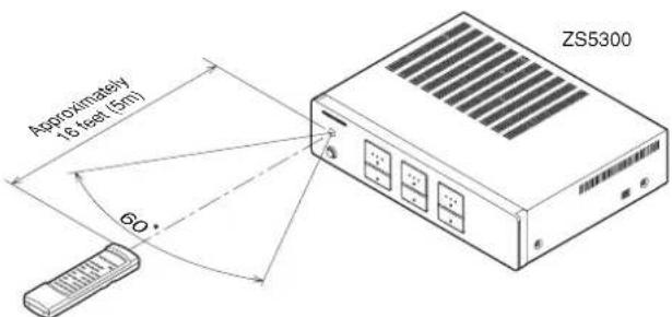
◆Using the remote control unit
1. Remote control
Operate the remote control unit (RC5300ZS) within a distance of approximately 16 feet (5m) from the IR (remote control) window on the front of the unit. If the transmitter is pointed to a direction other than the IR SENSOR or if there is an obstacle between them, remote control may not be possible.
- Remote control operating range
text_image
Approximately 18 feet (5m) 60° ZS5300Remote control unit
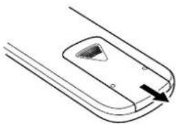
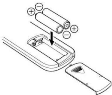
2. Loading batteries
Batteries in this remote control unit have a life of approximately 1 year under normal operating conditions. When the remote control unit is not to being used for an extended period of time, remove the batteries. Also, when you notice that the batteries are starting to run down, replace them as soon as possible.
- Remove the battery cover
natural_image
Simple line drawing of a mechanical component with a handle and mounting holes (no text or symbols)Note :
- Do not use the rechargeable batteries(Ni-Cd type).
- Insert the AA size batteries with correct (+) and (−) polarity.
text_image
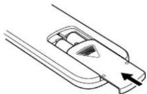
Diagram showing battery installation process with labeled positive and negative charges on a device handle- Close the battery cover until it clicks.
natural_image
Simple line drawing of a mechanical component with an arrow indicating direction (no text or symbols)ID Code Setup
Setting ID code
Ex.) Set to ID-1
Remote control unit

text_image
INPUT 2 3 VOLUME SET ID-1 ID-2 ID-3 REMOTE CONTROLLER RC5300ZSPress and hold SET, then Press ID-1 and release both.
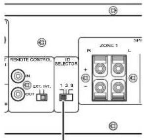
Rear panel of the unit
text_image
REMOTE CONTROL IN OUT EXT. INT. ID SELECTOR 1 2 3 R ZONE 1 L + - S/N ② ③Set to "1".
The ZS5300 system can be expanded up to 3 units.
When using 1 unit alone, set the ID switch on the rear panel to "1".
To set the remote control unit to the ID number of the unit, follow the procedure below.
1. Press the SET button and hold it, then press the ID-1 button, then release both buttons.
2. This remote control unit has been set as ID-1. To set the ID to 2 and 3, follow the same procedure.
3. When the batteries are replaced, the unit defaults to the factory setting of ID-1.
Note:
This is important, because if you have changed ID numbers, you will have to reset the ID number when the batteries are replaced.
*Default setting for both the remote control unit and the unit is ID-1
Preparation and Connection
◆Before making connections
Be sure to turn the power off for the ZS5300 and other products to be connected to ZS5300 before making connections. Please refer the instruction manuals for other products to make sure of the proper connections and terminals.
Keypad
The keypads that can be connected to the unit are keypads and connecting boxes made by NILES and XANTECH shown below. If you want to use products that are not in the list below or made by other manufacturers, please contact your authorized Marantz dealer.
• NILES
Keypad : IntelliPad
IR Main System unit : IRP6+
IR Sensor : MS 2
IR Flasher : IRC-2
• XANTECH
Keypad : SMARTPAD3
Connecting block : 789-44
IR Sensor : 480-30 Series
IR Emitter : 282M
Note:
When connecting a Keypad, refer to the instruction manual for the Keypad as well as for this unit.
Connecting speakers
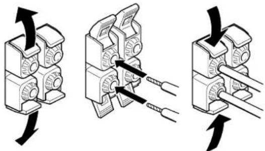
There are 2 ways to connect speakers. See the pictures below.
◆Connecting speaker wire
- Strip away approx. 6/8 inch (20 mm) of wire insulation.
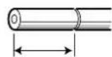
Approx. 6/8 inch (20 mm)
- Twist the bared wire ends tight to prevent short circuits.

natural_image
Diagram showing a cable being twisted into a wire, illustrating the process of winding and sheathing (no text or symbols present)- Insert the bare part of the wire into the hole in the each terminal as follow.
text_image
Diagram illustrating three steps of cable or cable clamp installation, showing mechanical assembly and wire connection.◆Connecting banana plug
Banana plug connections are also possible.

natural_image
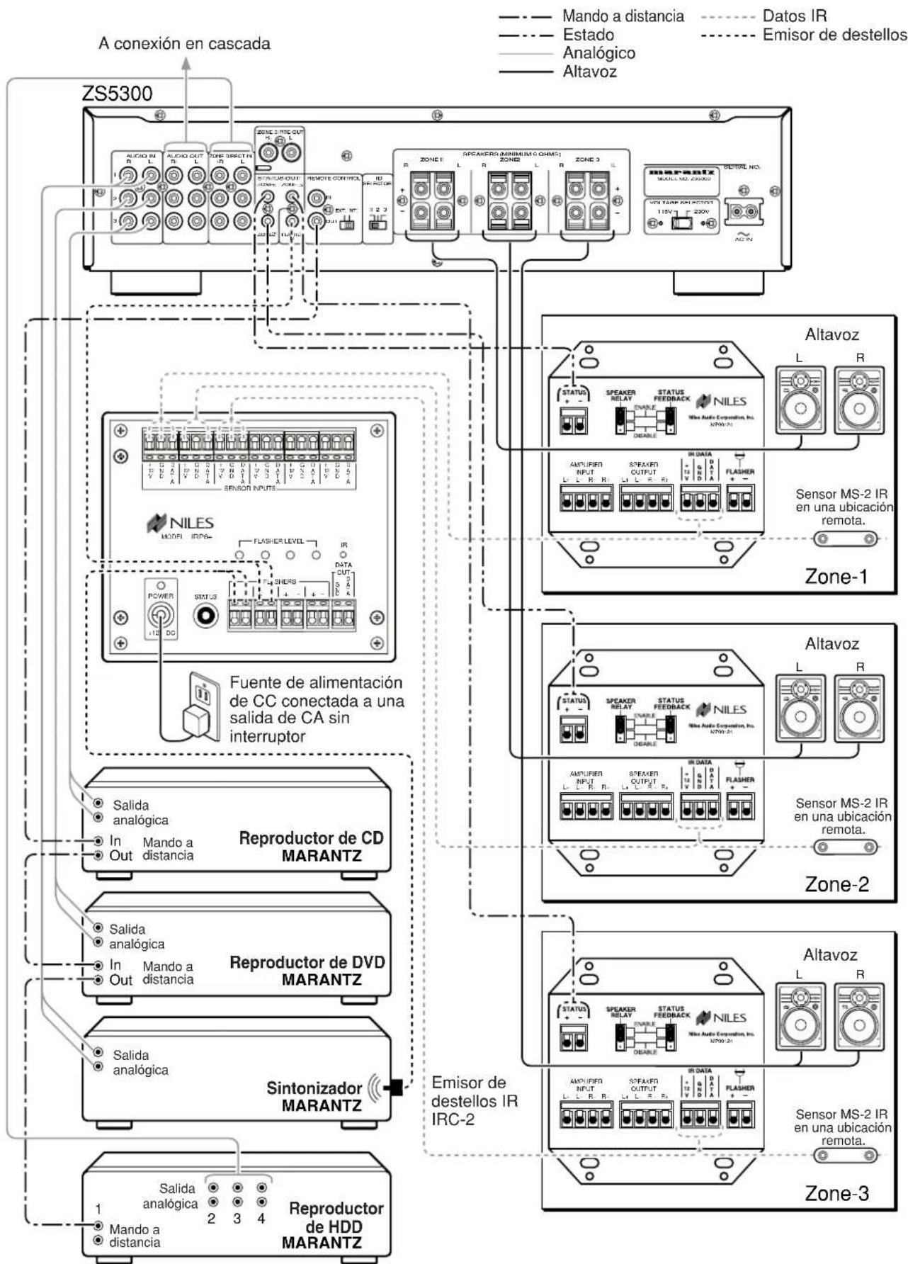
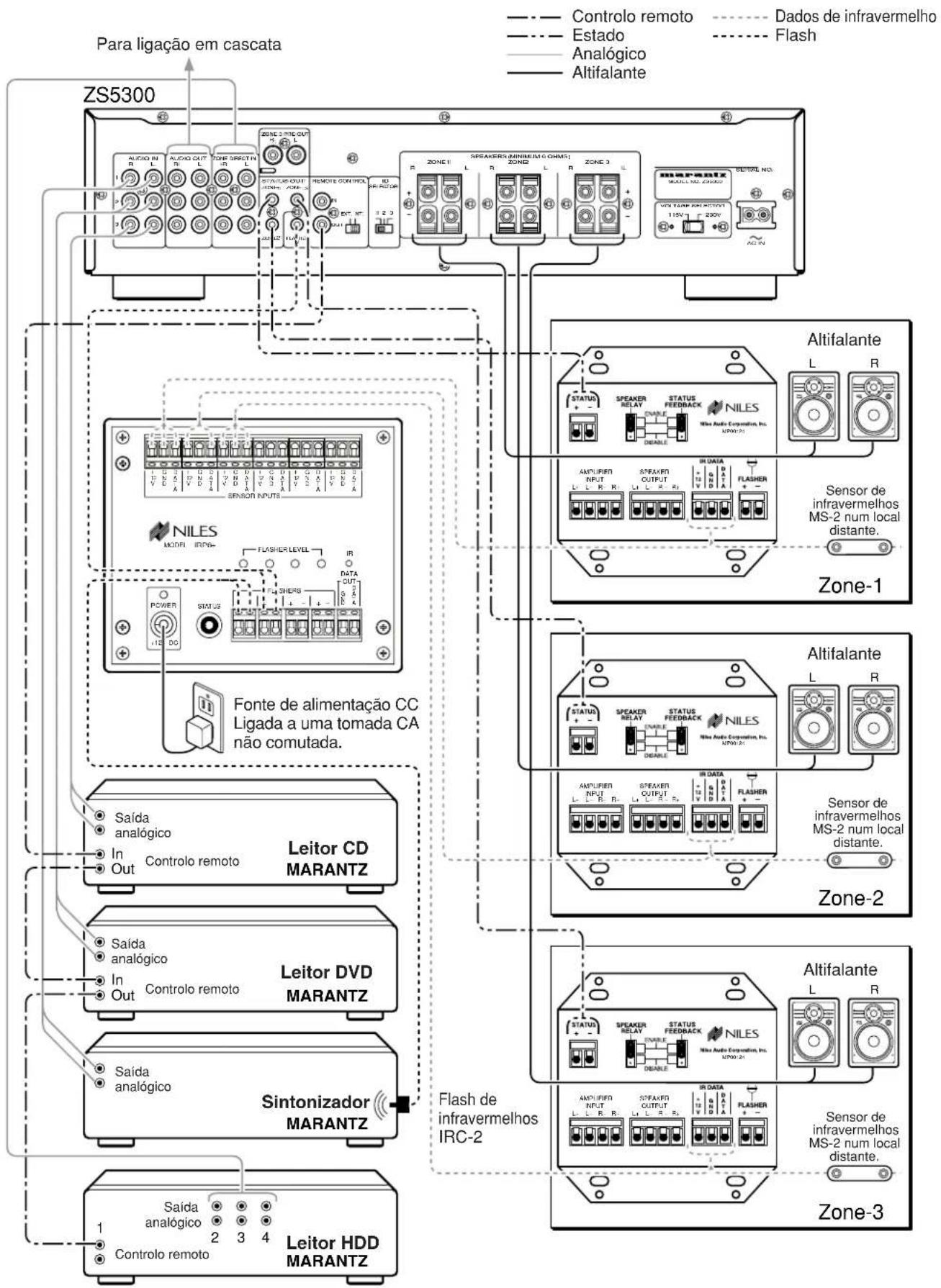
Diagram showing two connected cable connectors with arrows indicating connection points (no text or symbols)Connection example
◆NILES system

flowchart
graph TD
    A["ZS5300"] --> B["To cascade connection"]
    B --> C["Speaker"]
    C --> D["IR Data"]
    C --> E["Flasher"]
    B --> F["NILES"]
    F --> G["MS-2 IR Sensor in a remote location"]
    B --> H["CD Power supply plugged into an unswitched AC outlet."]
    H --> I["Speaker"]
    I --> J["IR Data"]
    I --> K["Flasher"]
    B --> L["MDI"]
    L --> M["MDI"]
    M --> N["MDI"]
    N --> O["MDI"]
    O --> P["MDI"]
    P --> Q["MDI"]
    Q --> R["MDI"]
    R --> S["MDI"]
    S --> T["MDI"]
    T --> U["MDI"]
    U --> V["MDI"]
    V --> W["MDI"]
    W --> X["MDI"]
    X --> Y["MDI"]
    Y --> Z["MDI"]
    Z --> AA["MDI"]
    AA --> AB["MDI"]
    AB --> AC["MDI"]
    AC --> AD["MDI"]
    AD --> AE["MDI"]
    AE --> AF["MDI"]
    AF --> AG["MDI"]
    AG --> AH["MDI"]
    AH --> AI["MDI"]
    AI --> AJ["MDI"]
    AJ --> AK["MDI"]
    AK --> AL["MDI"]
    AL --> AM["MDI"]
    AM --> AN["MDI"]
    AN --> AO["MDI"]
    AO --> AP["MDI"]
    AP --> AQ["MDI"]
    AQ --> AR["MDI"]
    AR --> AS["MDI"]
    AS --> AT["MDI"]
    AT --> AU["MDI"]
    AU --> AV["MDI"]
    AV --> AW["MDI"]
    AW --> AX["MDI"]
    AX --> AY["MDI"]
    AY --> AZ["MDI"]
    AZ --> BA["MDI"]
    BA --> BB["MDI"]
    BB --> BC["MDI"]
    BC --> BD["MDI"]
    BD --> BE["MDI"]
    BE --> BF["MDI"]
    BF --> BG["MDI"]
    BG --> BH["MDI"]
    BH --> BI["MDI"]
    BI --> BJ["MDI"]
    BJ --> BK["MDI"]
    BK --> BL["MDI"]
    BL --> BM["MDI"]
    BM --> BN["MDI"]
    BN --> BO["MDI"]
    BO --> BP["MDI"]
    BP --> BQ["MDI"]
    BQ --> BR["MDI"]
    BR --> BS["MDI"]
    BS --> BT["MDI"]
    BT --> BU["MDI"]
    BU --> BV["MDI"]
    BV --> BW["MDI"]
    BW --> BX["MDI"]
    BX --> BY["MDI"]
    BY --> BZ["MDI"]

flowchart
graph TD
    A["ZS5300"] --> B["To cascade connection"]
    B --> C["Speaker"]
    C --> D["480-30 series IR Receivers"]
    D --> E["7-foot ribbon cable with mini plug removed"]
    B --> F["Speaker"]
    F --> G["480-30 series IR Receivers"]
    G --> H["7-foot ribbon cable with mini plug removed"]
    B --> I["Speaker"]
    I --> J["480-30 series IR Receivers"]
    J --> K["7-foot ribbon cable with mini plug removed"]
    B --> L["Speaker"]
    L --> M["480-30 series IR Receivers"]
    M --> N["7-foot ribbon cable with mini plug removed"]
    B --> O["Speaker"]
    O --> P["480-30 series IR Receivers"]
    P --> Q["7-foot ribbon cable with mini plug removed"]
    B --> R["Speaker"]
    R --> S["480-30 series IR Receivers"]
    S --> T["7-foot ribbon cable with mini plug removed"]
    B --> U["Speaker"]
    U --> V["480-30 series IR Receivers"]
    V --> W["7-foot ribbon cable with mini plug removed"]
    B --> X["Speaker"]
    X --> Y["480-30 series IR Receivers"]
    Y --> Z["7-foot ribbon cable with mini plug removed"]
    B --> AA["Speaker"]
    AA --> AB["480-30 series IR Receivers"]
    AB --> AC["7-foot ribbon cable with mini plug removed"]
    B --> AD["Speaker"]
    AD --> AE["480-30 series IR Receivers"]
    AE --> AF["7-foot ribbon cable with mini plug removed"]
    B --> AG["Speaker"]
    AG --> AH["480-30 series IR Receivers"]
    AH --> AI["7-foot ribbon cable with mini plug removed"]
◆ Cascade connection
Note:
To change the positions of the EXT./INT. switch and the ID switch, turn off the main power switch of the ZS5300. When the main power switch is on, changing the positions do not affect.
flowchart
graph TD
    subgraph ZS5300 (Master)
        A1["AVOID IN"] --> B1["AUDIO OUT"]
        A2["AVOID OUT"] --> B2["ZONE DIRECT"]
        A3["AVOID IN"] --> B3["ZONE OUT"]
        A4["AVOID IN"] --> B4["ZONE DIRECT"]
        A5["AVOID IN"] --> B5["ZONE OUT"]
        A6["AVOID IN"] --> B6["ZONE DIRECT"]
        A7["AVOID IN"] --> B7["ZONE OUT"]
        A8["AVOID IN"] --> B8["ZONE DIRECT"]
        A9["AVOID IN"] --> B9["ZONE OUT"]
        A10["AVOID IN"] --> B10["ZONE DIRECT"]
        A11["AVOID IN"] --> B11["ZONE OUT"]
        A12["AVOID IN"] --> B12["ZONE DIRECT"]
        A13["AVOID IN"] --> B13["ZONE OUT"]
        A14["AVOID IN"] --> B14["ZONE DIRECT"]
        A15["AVOID IN"] --> B15["ZONE OUT"]
        A16["AVOID IN"] --> B16["ZONE DIRECT"]
        A17["AVOID IN"] --> B17["ZONE OUT"]
        A18["AVOID IN"] --> B18["ZONE DIRECT"]
        A19["AVOID IN"] --> B19["ZONE OUT"]
        A20["AVOID IN"] --> B20["ZONE DIRECT"]
        A21["AVOID IN"] --> B21["ZONE OUT"]
        A22["AVOID IN"] --> B22["ZONE DIRECT"]
        A23["AVOID IN"] --> B23["ZONE OUT"]
        A24["AVOID IN"] --> B24["ZONE DIRECT"]
        A25["AVOID IN"] --> B25["ZONE OUT"]
        A26["AVOID IN"] --> B26["ZONE DIRECT"]
        A27["AVOID IN"] --> B27["ZONE OUT"]
        A28["AVOID IN"] --> B28["ZONE DIRECT"]
        A29["AVOID IN"] --> B29["ZONE OUT"]
        A30["AVOID IN"] --> B30["ZONE DIRECT"]
        A31["AVOID IN"] --> B31["ZONE OUT"]
        A32["AVOID IN"] --> B32["ZONE DIRECT"]
        A33["AVOID IN"] --> B33["ZONE OUT"]
        A34["AVOID IN"] --> B34["ZONE DIRECT"]
        A35["AVOID IN"] --> B35["ZONE OUT"]
        A36["AVOID IN"] --> B36["ZONE DIRECT"]
        A37["AVOID IN"] --> B37["ZONE OUT"]
        A38["AVOID IN"] --> B38["ZONE DIRECT"]
        A39["AVOID IN"] --> B39["ZONE OUT"]
        A40["AVOID IN"] --> B40["ZONE DIRECT"]
        A41["AVOID IN"] --> B41["ZONE OUT"]
        A42["AVOID IN"] --> B42["ZONE DIRECT"]
        A43["AVOID IN"] --> B43["ZONE OUT"]
        A44["AVOID IN"] --> B44["ZONE DIRECT"]
        A45["AVOID IN"] --> B45["ZONE OUT"]
        A46["AVOID IN"] --> B46["ZONE DIRECT"]
        A47["AVOID IN"] --> B47["ZONE OUT"]
        A48["AVOID IN"] --> B48["ZONE DIRECT"]
        A49["AVOID IN"] --> B49["ZONE OUT"]
        A50["AVOID IN"] --> B50["ZONE DIRECT"]
        A51["AVOID IN"] --> B51["ZONE OUT"]
        A52["AVOID IN"] --> B52["ZONE DIRECT"]
        A53["AVOID IN"] --> B53["ZONE OUT"]
        A54["AVOID IN"] --> B54["ZONE DIRECT"]
        A55["AVOID IN"] --> B55["ZONE OUT"]
        A56["AVOID IN"] --> B56["ZONE DIRECT"]
        A57["AVOID IN"] --> B57["ZONE OUT"]
        A58["AVOID IN"] --> B58["ZONE DIRECT"]
        A59["AVOID IN"] --> B59["ZONE OUT"]
        A60["AVOID IN"] --> B60["ZONE DIRECT"]
        A61["AVOID IN"] --> B61["ZONE OUT"]
        A62["AVOID IN"] --> B62["ZONE DIRECT"]
        A63["AVOID IN"] --> B63["ZONE OUT"]
        A64["AVOID IN"] --> B64["ZONE DIRECT"]
        A65["AVOID IN"] --> B65["ZONE OUT"]
        A66["AVOID IN"] --> B66["ZONE DIRECT"]
        A67["AVOID IN"] --> B67["ZONE OUT"]
        A68["AVOID IN"] --> B68["ZONE DIRECT"]
        A69["AVOID IN"] --> B69["ZONE OUT"]
        A70["AVOID IN"] --> B70["ZONE DIRECT"]
        A71["AVOID IN"] --> B71["ZONE OUT"]
        A72["AVOID IN"] --> B72["ZONE DIRECT"]
        A73["AVOID IN"] --> B73["ZONE OUT"]
        A74["AVOID IN"] --> B74["ZONE DIRECT"]
        A75["AVOID IN"] --> B75["ZONE OUT"]
        A76["AVOID IN"] --> B76["ZONE DIRECT"]
        A77["AVOID IN"] --> B77["ZONE OUT"]
        A78["AVOID IN"] --> B78["ZONE DIRECT"]
        A79["AVOID IN"] --> B79["ZONE OUT"]
        A80["AVOID IN"] --> B80["ZONE DIRECT"]
        A81["AVOID IN"] --> B81["ZONE OUT"]
        A82["AVOID IN"] --> B82["ZONE DIRECT"]
        A83["AVOID IN"] --> B83["ZONE OUT"]
        A84["AVOID IN"] --> B84["ZONE DIRECT"]
        A85["AVOID IN"] --> B85["ZONE OUT"]
        A86["AVOID IN"] --> B86["ZONE DIRECT"]
        A87["AVOID IN"] --> B87["ZONE OUT"]
        A88["AVOID IN"] --> B88["ZONE DIRECT"]
        A89["AVOID IN"] --> B89["ZONE OUT"]
        A90["AVOID IN"] --> B90["ZONE DIRECT"]
        A91["AVOID IN"] --> B91["ZONE OUT"]
        A92["AVOID IN"] --> B92["ZONE DIRECT"]
        A93["AVOID IN"] --> B93["ZONE OUT"]
        A94["AVOID IN"] --> B94["ZONE DIRECT"]
        A95["AVOID IN"] --> B95["ZONE OUT"]
        A96["AVOID IN"] --> B96["ZONE DIRECT"]
        A97["AVOID IN"] --> B97["ZONE OUT"]
        A98["AVOID IN"] --> B98["ZONE DIRECT"]
        A99["AVOID IN"] --> B99["ZONE OUT"]
    end

    subgraph ZS5300 (Slave)
        C1["AUDIO OUT H"]
        C2["AUDIO OUT L"]
        C3["AUDIO OUT H L"]
    end

    subgraph ZS5300 (Slave)
        D1["AUDIO OUT H"]
        D2["AUDIO OUT L"]
    end

    subgraph ZS5300 (Slave)
        E1["AUDIO OUT H"]
    end

    subgraph ZS5300 (Slave)
        F1["AUDIO OUT H L"]
    end

    subgraph ZS5300 (Slave)
        G1["AUDIO OUT H L"]
    end

    subgraph ZS5300 (Slave)
        H1["AUDIO OUT H L"]
    end

    subgraph ZS5300 (Slave)
        I1["AUDIO OUT H L"]
    end

    subgraph ZS5300 (Slave)
        J1["AUDIO OUT H L"]

    subgraph ZS5300 (Slave)
    K1["SPEAKENS (MINIMUM 8 CHIME)"]
    K2["SPEAKENS (MINIMUM 8 CHIME)"]
    K3["SPEAKENS (MINIMUM 8 CHIME)"]
    K4["SPEAKENS (MINIMUM 8 CHIME)"]
    K5["SPEAKENS (MINIMUM 8 CHIME)"]
    K6["SPEAKENS (MINIMUM 8 CHIME)"]
    K7["SPEAKENS (MINIMUM 8 CHIME)"]
    K8["SPEAKENS (MINIMUM 8 CHIME)"]
    K9["SPEAKENS (MINIMUM 8 CHIME)"]
    K10["SPEAKENS (MINIMUM 8 CHIME)"]
    K11["SPEAKENS (MINIMUM 8 CHIME)"]
    K12["SPEAKENS (MINIMUM 8 CHIME)"]
    K13["SPEAKENS (MINIMUM 8 CHIME)"]
    K14["SPEAKENS (MINIMUM 8 CHIME)"]
    K15["SPEAKENS (MINIMUM 8 CHIME)"]
    K16["SPEAKENS (MINIMUM 8 CHIME)"]
    K17["SPEAKENS (MINIMUM 8 CHIME)"]
    K18["SPEAKENS (MINIMUM 8 CHIME)"]
    K19["SPEAKENS (MINIMUM 8 CHIME)"]
    K20["SPEAKENS (MINIMUM 8 CHIME)"]
    K21["SPEAKENS (MINIMUM 8 CHIME)"]
    K22["SPEAKENS (MINIMUM 8 CHIME)"]
    K23["SPEAKENS (MINIMUM 8 CHIME)"]
    K24["SPEAKENS (MINIMUM 8 CHIME)"]
    K25["SPEAKENS (MINIMUM 8 CHIME)"]
    K26["SPEAKENS (MINIMUM 8 CHIME)"]
    K27["SPEAKENS (MINIMUM 8 CHIME)"]
    K28["SPEAKENS (MINIMUM 8 CHIME)"]
    K29["SPEAKENS (MINIMUM 8 CHIME)"]
    K30["SPEAKENS (MINIMUM 8 CHIME)"]
    K31["SPEAKENS (MINIMUM 8 CHIME)"]
    K32["SPEAKENS (MINIMUM 8 CHIME)"]
    K33["SPEAKENS (MINIMUM 8 CHIME)"]
    K34["SPEAKENS (MINIMUM 8 CHIME)"]
    K35["SPEAKENS (MINIMUM 8 CHIME)"]
    K36["SPEAKENS (MINIMUM 8 CHIME)"]
    K37["SPEAKENS (MINIMUM 8 CHIME)"]
    K38["SPEAKENS (MINIMUM 8 CHIME)"]
    K39["SPEAKENS (MINIMUM 8 CHIME)<br><br>    subgraph ZS5300<br>        L1[VOLTAGE SELECTOR 11.5V, P:2.6V, AC:IN"]

    M1["VOLTAGE SELECTOR 1.5V, P:2.6V, AC:IN"]

    N1["VOLTAGE SELECTOR 1.5V, P:2.6V, AC:IN"]

    O1["VOLTAGE SELECTOR 1.5V, P:2.6V, AC:IN"]

    P1["VOLTAGE SELECTOR 1.5V, P:2.6V, AC:IN"]

    Q1["VOLTAGE SELECTOR 1.5V, P:2.6V, AC:IN"]

    R1["VOLTAGE SELECTOR 1.5V, P:2.6V, AC:IN"]

    S1["VOLTAGE SELECTOR 1.5V, P:2.6V, AC:IN"]

    T1["VOLTAGE SELECTOR 1.5V, P:2.6V, AC:IN"]

    U1["VOLTAGE SELECTOR 1.5V, P:2.6V, AC:IN"]

    V1["VOLTAGE SELECTOR 1.5V, P:2.6V, AC:IN"]

    W1["VOLTAGE SELECTOR 1.5V, P:2.6V, AC:IN"]

    X1["VOLTAGE SELECTOR 1.5V, P:2.6V, AC:IN"]

    Y1["VOLTAGE SELECTOR 1.5V, P:2.6V, AC:IN"]

    Z1["VOLTAGE SELECTOR 1.5V, P:2.6V, AC:IN"]

    AA1["VOLTAGE SELECTOR 1.5V, P:2.6V, AC:IN"]

    AB1["VOLTAGE SELECTOR 1.5V, P:2.6V, AC:IN"]

    AC1["VOLTAGE SELECTOR 1.5V, P:2.6V, AC:IN"]

    AD1["VOLTAGE SELECTOR 1.5V, P:2.6V, AC:IN"]

    AE1["VOLTAGE SELECTOR 1.5V, P:2.6V, AC:IN"]

    AF1["VOLTAGE SELECTOR 1.5V, P:2.6V, AC:IN"]

    AG1["VOLTAGE SELECTOR 1.5V, P:2.6V, AC:IN"]

    AH1["VOLTAGE SELECTOR 1.5V, P:2.6V, AC:IN"]

    AI1["VOLTAGE SELECTOR 1.5V, P:2.6V, AC:IN"]

    AJ1["VOLTAGE SELECTOR 1.5V, P:2.6V, AC:IN"]

    AK1["VOLTAGE SELECTOR 1.5V, P:2.6V, AC:IN"]

    AL1["VOLTAGE SELECTOR 1.5V, P:2.6V, AC:IN"]

    AM1["VOLTAGE SELECTOR 1.5V, P:2.6V, AC:IN"]

    AN1["VOLTAGE SELECTOR 1.5V, P:2.6V, AC:IN"]

    AO1["VOLTAGE SELECTOR 1.5V, P:2.6V, AC:IN"]

    AP1["VOLTAGE SELECTOR 1.5V, P:2.6V, AC:IN"]

    AQ1["VOLTAGE SELECTOR 1.5V, P:2.6V, AC:IN"]

    AR1["VOLTAGE SELECTOR 1.5V, P:2.6V, AC:IN"]

    AS1["VOLTAGE SELECTOR 1.5V, P:2.6V, AC:IN"]

    AT1["VOLTAGE SELECTOR 1.5V, P:2.6V, AC:IN"]

    AU["XIOUTING MARANTZ"]
flowchart
graph TD
    subgraph ZS5300
        A["Speaker"] --> B["Zone-1"]
        C["Speaker"] --> D["Zone-2"]
        E["Speaker"] --> F["Zone-3"]
    end

    subgraph DH9300
        G["Audio"] --> H["Signal"]
        I["Remote"] --> J["Analog"]
        K["Video"] --> L["Speaker"]
        M["Audio"] --> N["Signal"]
        O["Remote"] --> P["Analog"]
        Q["Video"] --> R["Speaker"]
        S["Audio"] --> T["Signal"]
        U["Remote"] --> V["Analog"]
        W["Video"] --> X["Speaker"]
        Y["Audio"] --> Z["Signal"]
        AA["Remote"] --> AB["Analog"]
        AC["Video"] --> AD["Speaker"]
        AE["Audio"] --> AF["Signal"]
        AG["Remote"] --> AH["Analog"]
        AI["Video"] --> AJ["Speaker"]
        AK["Audio"] --> AL["Signal"]
        AM["Remote"] --> AN["Analog"]
        AO["Video"] --> AP["Speaker"]
        AQ["Audio"] --> AR["Signal"]
        AS["Remote"] --> AT["Analog"]
        AU["Video"] --> AV["Speaker"]
        AW["Audio"] --> AX["Signal"]
        AY["Sensor"] --> AZ["Voltage Selection 115V 220V"]
        BA["Sensor"] --> BB["Voltage Selection 115V 220V"]
        BC["Sensor"] --> BD["Voltage Selection 115V 220V"]
        BE["Sensor"] --> BF["Voltage Selection 115V 220V"]
        BG["Sensor"] --> BH["Voltage Selection 115V 220V"]
        BI["Sensor"] --> BJ["Voltage Selection 115V 220V"]
        BK["Sensor"] --> BL["Voltage Selection 115V 220V"]
    end

    style ZS5300 fill:#f9f,stroke:#333
    style DH9300 fill:#ccf,stroke:#333
◆Connecting external power amplifier
When using speakers which might need high power to drive (ex. some outdoor speakers), you might need more power than the ZS5300 can provide. If you need more power, you can connect the "ZONE 3 PRE OUT" to an external power amplifier.
Sound level can be adjusted with Volume Up/Down on ZS5300.
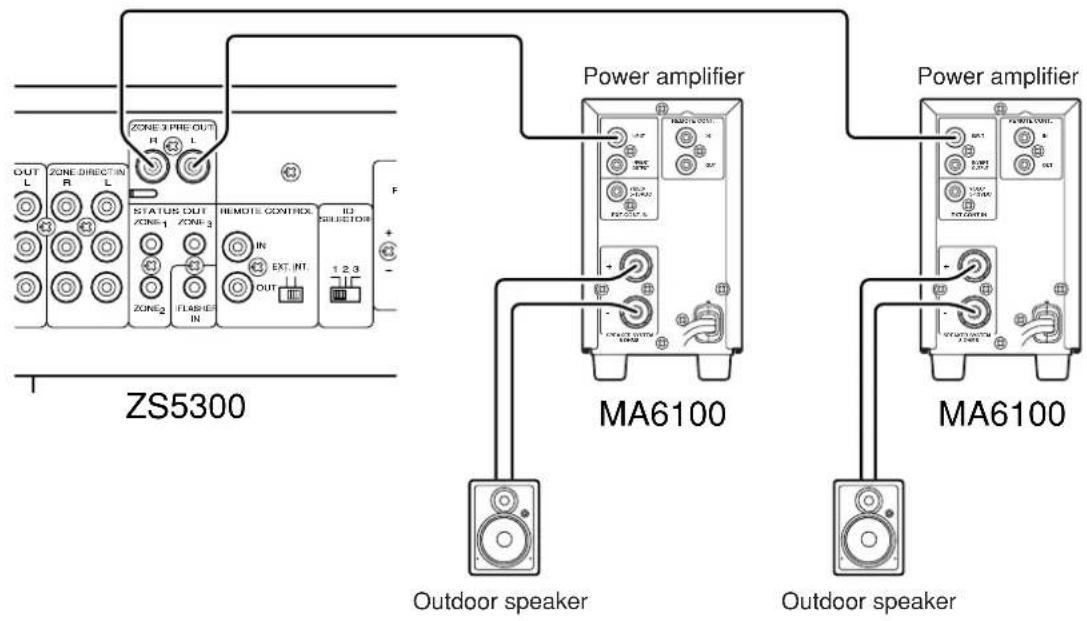
text_image
ZS5300 OUT L ZONE DIRECT IN R L STATUS OUT ZONE-1 ZONE-3 IN EXT INT FLASH IN REMOTE CONTREX 1 2 3 F Power amplifier MA6100 Outdoor speaker Power amplifier MA6100 Outdoor speaker◆Connecting power cord
When all the connections are made, plug the power cord into the power outlet.
Setup
This is an example to construct 3-zone system with a NILES keypad.
See the picture Connection Example "NILES system" (P. 10).
When all the connections are made, teach the keypad the remote commands.
To teach the commands to the keypad or more information, please refer to the instruction manual of your keypads.
Operation Examples
✿Refer to connection example "NILES system" ( P.10)
Main room
ZONE 1

text_image
1. light up ZONE 1 1. light up 3. light up 4. flash
text_image
1. 2. CO DVD TUNER VCR LASEH SAT POWER 5. STOP PACK - MOS VOLUME VOLUME 3. 4.1. 6.- Press the CD button on the keypad. The power of ZS5300's Zone 1 is turned on and the input source is switched to Input 3. Pressing the POWER button on the keypad also turns on the power.
- Press the PLAY button on the keypad. CD player begins to play.
- Press the VOLUME ▲ button on the keypad. The volume level of ZS5300's Zone 1 is increased. Also pressing the VOLUME ▼ button decreases the volume level.
- Press the MUTE button on the keypad to mute the sound. The volume level indicators of ZS5300's Zone 1 flashes. To release the mute, press the MUTE button again or press the VOLUME ▲ or ▼.
- Press the STOP button on the keypad. The CD player stops.
- Press the POWER button on the keypad. The power of ZS5300's Zone 1 is turned off and the STANDBY indicator lights up.
◆Remote code list (RC-5 extension)
| FUNCTION ID-1 ID-2 ID-3 Note | ||||
| Global Power ON/OFF 161210 | 161210 161 | 210 Global control code | ||
| Global Power ON 161211 161 | 211 161211 | Global control code | ||
| Global Power OFF 161212 16 | 212 161212 | Global control code | ||
| Global Volume up 161600 161 | 600 161600 | Global control code | ||
| Global Volume down 161700 | 161700 1617 | 00 Global control code | ||
| Global Mute 161319 161319 | 161319 Global control code | |||
| Global INPUT 1 160039 160039 | 160039 Global control code | |||
| Global INPUT 2 160049 160049 | 160049 Global control code | |||
| Global INPUT 3 160059 160059 | 160059 Global control code | |||
| Global Direct in 160060 160060 | 160060 Global control code | |||
| Zone 1 Power ON/OFF 161220 | 161223 161 | 226 | ||
| Zone 1 Power ON 161221 161 | 224 161227 | |||
| Zone 1 Power OFF 161222 16 | 1225 161228 | |||
| Zone 1 INPUT 1 160030 160033 | 160036 | |||
| Zone 1 INPUT 2 160031 160034 | 160037 | |||
| Zone 1 INPUT 3 160032 160035 | 160038 | |||
| Zone 1 Direct in 160017 160018 | 160019 | |||
| Zone 1 Mute ON/OFF 161310 | 161313 161 | 316 | ||
| Zone 1 Volume up 161610 16 | 1613 161616 | |||
| Zone 1 Volume down 161710 | 161713 1617 | 16 | ||
| Zone 2 Power ON/OFF 161230 | 161233 161 | 236 | ||
| Zone 2 Power ON 161231 161 | 234 161237 | |||
| Zone 2 Power OFF 161232 16 | 1235 161238 | |||
| Zone 2 INPUT 1 160040 160043 | 160046 | |||
| Zone 2 INPUT 2 160041 160044 | 160047 | |||
| Zone 2 INPUT 3 160042 160045 | 160048 | |||
| Zone 2 Direct in 160024 160025 | 160026 | |||
| Zone 2 Mute ON/OFF 161311 | 161314 161 | 317 | ||
| Zone 2 Volume up 161611 16 | 1614 161617 | |||
| Zone 2 Volume down 161711 | 161714 1617 | 17 | ||
| Zone 3 Power ON/OFF 161240 | 161243 161 | 246 | ||
| Zone 3 Power ON 161241 161 | 244 161247 | |||
| Zone 3 Power OFF 161242 16 | 1245 161248 | |||
| Zone 3 INPUT 1 160050 160053 | 160056 | |||
| Zone 3 INPUT 2 160051 160054 | 160057 | |||
| Zone 3 INPUT 3 160052 160055 | 160058 | |||
| Zone 3 Direct in 160027 160028 | 160029 | |||
| Zone 3 Mute ON/OFF 161312 | 161315 161 | 318 | ||
| Zone 3 Volume up 161612 16 | 1615 161618 | |||
| Zone 3 Volume down 161712 | 161715 1617 | 18 | ||
| Setup | Set | ---- | ---- | ---- |
| Setup | ID-1 | ---- | ---- | ---- |
| Setup | ID-2 | ---- | ---- | ---- |
| Setup | ID-3 | ---- | ---- | ---- |
ID initial : ID-1
ID setting : Push and hold SET first and ID-* buttons next simultaneously. (*=1 or 2 or 3)
Troubleshooting
In case of trouble with the unit, first check the following before calling for service.
- Are all the connections made properly?
- Are you operating the unit properly by following user's guide?
- Are the other products working properly?
If the unit still does not work properly, check the items shown in the following table.
If your trouble cannot be solved with the remedy actions listed in the following table, malfunction of the internal circuitry is suspected; immediately unplug the AC power cord and contact a Marantz authorized dealer or service center.
| Problem | Remedy |
| The amplifier does not work and the indicator does not light up. | ·Check if the power cord is plugged properly into an AC power outlet. |
| The indicator lights up but the amplifier will not function. | ·Check the settings of the INPUT SELECTOR, VOLUME control.·Check if the MUTE function is de-activated. (The MUTE indicator is OFF.) |
| Sound is produced only from one of the speaker systems. | ·Turn the power off and change the connections of the left and right speaker systems. If sound still does not come out from the same speaker system, check the connection cords or the speaker system itself. |
| Sound is not produced at all. | ·Check the settings of the INPUT SELECTOR.·Check that the speaker cords are connected properly.·Check that the connection cords with RCA pin plugs are connected properly. |
| Doesn't work properly when it is connected to Cascade. | ·Check the ID switch of the rear panel is set properly.·Check the ID setting of the remote controller is set properly. |
Care and Maintenance
This section describes the care and maintenance tasks that must be performed to optimize the operation of your Marantz equipment.
◆Cleaning of the external surfaves of the unit
The exterior finish of your unit will last indefinitely with proper care and cleaning. Never use scouring pads, steel wool, scouring powders or harsh chemical agents, alcohol, thinners, benzene, insecticide or other volatile substances as these will mar the finish of the equipment. Likewise, never use cloths containing chemical substances. If the unit gets dirty, wipe the external surfaces with a soft, lint-free cloth.
Specification
Rated power output
Zone1 L/R (40Hz -20KHz) 60W 6-ohm / Channel
Zone2 L/R (40Hz -20KHz) 60W 6-ohm / Channel
Zone3 L/R (40Hz -20KHz) 60W 6-ohm / Channel
THD (40Hz - 20KHz) 0.05% 6-ohm
Input sensitivity 300mV / 60W Output
Input impedance 20K ohms
Frequency response (-1dB) 10Hz to 30KHz
Signal to noise ratio 85dB
Power requirement 115V / 230V AC 50/60Hz
Power consumption 100W
Dimensions (Maximum)
Width 17.32 inches (440 mm)
Height 4.53 inches (115 mm)
Depth 13.31 inches (338 mm)
Weight 18.74 lbs (8.5 Kg)
Accessories
AC power cord 1
Remote control unit (RC5300ZS)....1
AA-size batteries 2
Design and specifications are subject to change without notice.
Table des matières
Introduction......2
natural_image
Line drawing of a cable with two connectors and a connector terminal (no text or symbols)• Télécommande x 1
text_image
Diagram of a remote control with labeled buttons and ports, showing various function keys and status indicators.- Piles de type AA x 2

natural_image
Two cylindrical batteries shown in line drawing style (no text or symbols)natural_image
Simple line drawing of a mechanical component with a handle and mounting holes (no text or symbols)Remarque :
text_image
Diagram showing battery installation process with labeled positive and negative charges on a device handlenatural_image
Simple line drawing of a mechanical component with an arrow indicating direction (no text or symbols)natural_image
Diagram showing a cable being twisted into a wire, illustrating the process (no text or symbols present)text_image
Diagram illustrating three steps of cable clamp installation, showing mechanical assembly and wire connection.natural_image
Diagram of two connectors inserted into a multi-pin connector (no text or symbols visible)natural_image
Line drawing of a cable with two connectors and a connector terminal (no text or symbols)text_image
Diagram of a remote control with labeled buttons and ports, showing various function keys and function descriptions.natural_image
Two cylindrical batteries shown in a row (no text or symbols)natural_image
Pure technical line drawing of a mechanical component with no text or symbolsNota:
text_image
Diagram showing battery installation process with labeled positive and negative charges on a device handlenatural_image
Simple line drawing of a mechanical component with an arrow indicating direction (no text or symbols)natural_image
Diagram showing a cable being twisted into a wire, illustrating the process (no text or symbols present)text_image
Diagram illustrating three steps of cable clamp installation, showing mechanical assembly and wire connection.natural_image
Diagram of two mechanical components with arrows indicating connection points (no text or symbols)Ejemplo de conexión
Sistema NILES
natural_image
Line drawing of a cable with two connectors and a connector terminal (no text or symbols)text_image
Diagram of a remote control with labeled buttons and ports, showing various function keys and status indicators.natural_image
Two cylindrical batteries shown in a row (no text or symbols)natural_image
Pure technical line drawing of a mechanical component with no text or symbolsNota :
text_image
Diagram showing battery installation process with labeled positive and negative charges on a device panelnatural_image
Simple line drawing of a mechanical component with an arrow indicating direction (no text or symbols)natural_image
Diagram showing a cable being twisted into a wire, illustrating the process (no text or symbols present)text_image
Diagram illustrating three steps of cable or cable clamp installation, showing mechanical assembly and wire connection.natural_image
Diagram of two mechanical components with arrows indicating connection points (no text or symbols)Exemplo de ligação
Sistema NILES
COUNTRY COMPANY ADDRESS
| ALGERIE Azur 2000 8, Lotissement Ben Hatadi, Alger, Algerie | ||
| ARMENIA NGYIG Ltd. 47 A/75 St. Lalaiants, 375000 Yerevan, Armenia | ||
| AUSTRALIA QualiFi Pty. Ltd., P.O. Box 350, Mt. Waverley, VIC 3149, Australia | ||
| AUSTRIA | Huber & Prohaska GmbH | Taborstraße 95 / Ladestraße 1, Gebäude Hangartner, A-1200 Wien, Austria |
| BAHREIN Ambassador Stores P.O. Box 237,141, Government Avenue, Manama,Bahrein | ||
| BANGLADESH Target 1078, Ramjoy Mohanja Lane Asadgonj, Chittagong 4000, Bangladesh | ||
| BELGIUM Van der Heyden Audio N.V. Brusselbaan 278, 9320 Erembodegem, Belgium | ||
| BULGARIA | Ariescommerce GmbH | Makedonia Blvd. 16, 1606 Sofia, Bulgaria |
| CANADA | Lenbrook Industries Limited | 633 Granite Court, Pickering, Ontario |
| CHINA | Guang Chang Audio International Co., Ltd. | No.38 Yushan Road, ShiQiao, Pan Yu, Guang Dong, China |
| CYPRUS | Empire Hifi systems Ltd. | P.O. Box 5604, Nicosia, Cyprus |
| CZECH REPUBLIC | Audio International | Sokolska 41, 67902 Rajecko, OKR,Blansko, Czech Republic |
| DENMARK | Audio Nord | Dali Allé 1, 9610 Noerager, Denmark |
| DUBAI | V.V.& SONS | P.O. Box 105, Dubai, U.A.E. |
| EGYPT | Solimco | 9, El Attibaa St. Doki, Cairo, Egypt |
| ESTONIA HiFi Club Estonia | Ehte 4, 90503 Haapsalu, Estonia | |
| F.Y.R.O.M. | T.P. KODI | ul.Cedomir Kantargiev 21a, Skopje, Former Yugoslavian Republic of Macedonija |
| FINLAND | Audio Nord | Uudenmaankatu 4-6, Helsinki SF-00120, Finland |
| FRANCE | Marantz France | A division of Marantz Europe B.V., P.O. Box 301, 92 156 Suresnes Cedex, France |
| GERMANY | Marantz Deutschland | Hakenbusch 3, 49078 Osnabrück, Germany |
| GREECE | Adamco S.A. | 188, Hippocratous Street, 11471 Athens, Greece |
| HEADQUARTERS EUROPE: | Marantz Europe B.V. | P.O. Box 8744, 5605 LS Eindhoven, The Netherlands |
| HONG KONG | Marantz Hong Kong Ltd. | Unit 1706, Metroplaza II, 223 Hing Fong Road, Kwai Fong, N.T., Kowloon, Hong Kong |
| HUNGARY | Infovox Ltd. Terez Krt.31, 1067 Budapest, Hungary | |
| ICELAND ID Electronics Ltd. | Armula 38, 108 Reykjavik, Iceland | |
| INDIA | NOVA Audio Private | 8,Punam Co-op.Society 29/30 Road#5, Union Park MUMBAI 400052, India |
| IRAN | Home Co. | 5th floor no 878 Philips Building Enghelab ave, P.O. 11365/7844 Tehran, Iran |
| IRELAND Marantz Ireland | Clonskeagh, Dublin 14, Ireland | |
| ISRAEL | Elmor Ltd. | 52 Heh Beiyar Street, Kikar Hamedina, Tel Aviv, Israel |
| ITALY | Marantz Italy | Via Casati 23, 20052 Monza (Milano), Italy, Servizio Consumatori 1678-20026, Numero Verde |
| IVORY COAST | Hifivoir | B.P. 2428, Abidjan 01, Ivory Coast |
| JAPAN | Marantz Japan Inc. | 35-1 Sagami Ohno 7-Chome, Sagamihara-shi, Kanagawa 228-8505, Japan |
| KOREA | MK Enterprises Ltd. | Rm604, Electro-officetel, 16-58, Hangang-ro 3Ga, Yongsan-Ku, Seoul, Korea |
| KUWAIT | alAlamiah Electronics Intl. | P.O. Box 8196, Salmiah 22052, Kuwait |
| LATVIA | Ace Ltd. | 61, LacPlesa Str., Riga LV 1011, Latvia |
| LEBANON AZ Electronics S.A., 1, | P.O. Box 11 2833, Beirut, Lebanon | |
| LITHUANIA | Accapella Ltd. | Ausrros, Vartu G/5, Pasazo SKG., 2001 Vilnius, Lithuania |
| MALAYSIA | Wo Kee Hong Electronics Sdn. Bhd. | 2nd Floor Bangnan Infinite Centre, Lot1, Jalan 13/6, 46200 Petaling Jaya, Selangor Datul Ehsan, Malaysia |
| MALTA | Doneo Co Ltd. | 78 The Strand, Sliema SLM07, Malta |
| MAURITIUS | SKR Electronics Ltd. | P.O. Box 685, Bell Village, Port Louis, Mauritius |
| MILITARY MARKET EUROPE | PASCO GmbH | PO BOX 1280, Sandhausen 69200, Germany |
| NEW ZEALAND | Wildash Audio Systems | 14 Malvern Road, Mt. Albert, Auckland, New Zealand |
| NORWAY Audio Nord | Sandkerveien 64, Oslo 0483, Norway | |
| OMAN | Mustafa & Jawad Trading CO. | P.O. Box 1918, Ruwi, Oman |
| POLAND | Philips Polska Sp. z.o.o. | Al.Jerozolimskie 195b, 02 222 Warszawa, Poland |
| PORTUGAL | Corel2 | Comércio de Electrónica Lda., Av. Luis Bívar, No 85 A, 1050 Lisboa, Portugal |
| PROFESSIONAL EUROPE | Marantz Professional Products | Kingsbridge House, Padbury Oaks, 575-583 Bath Road, Longford, Middlesex UB7 0EH, U.K. |
| PROFESSIONAL U.S.A. | Marantz Professional Products | Distributed by: Superscope Technologies Inc., 1000 Corporate Blvd. Ste.D, Aurora, Illino |
| QATAR | Almana & Partners W.W.L. | P.O. Box 49, Doha, Qatar |
| REUNION | Vision + | 180 Rue du Marechal Leclerc, 97400 Saint Denis, Ile de la Reunion |
| ROMANIA | Nova Music Entertainment | 5, Zagazului Str. Bl.1G,apt.18, sector 1,Bucharest, Romania |
| RUSSIA | Absolute Audio 7/2, Montazhnaya Street, 107497 Moscow, Russia | |
| SAUDI ARABIA | Adawlia Univ. Electr. Apl | P.O. Box 2154, Alkhobar 31952, Saudi Arabia |
| SINGAPORE | Wo Kee Hong Distribution PTE Ltd. | 130 Joo Seng Road, #03-02 Olivine Building, Singapore 368357 |
| SLOVAKIA | Bis Audio s.r.o. Nam. SNP 10, 96001 Zvolem, Slovakia | |
| SLOVENIA | Bofex | Smartinska 152, HALA V/3, 61000 Ljubljana, Slovenia |
| SOUTH AFRICA | Coherent Imports (PTY) Ltd. | P.O. Box 1614, Alberton, 1450, South Africa |
| SPAIN | Marantz Spain | Martinez Villergas 2, Apartado 2065, Madrid 28027, Spain |
| SRI LANKA | The listening Room | Mezzanine Floor, The Landmark 385, Galle Road, Colombo - 3, Sri Lanka |
| SWEDEN | Audio Nord | Almedalsvagen 4, Gotenborg 402-23, Sweden |
| SWITZERLAND | Sound Company AG | Postfach, 8010 Zürich, Switzerland |
| SYRIA | Hamzeh & Partners | Hafez Ibrahim Str. No 117, Damascus Shalan, Syria |
| TAHITI | Covecolor | Av. Prince Hinoi, Cours de l'union sacré, P.O. Box 2334, Papeete, Tahiti |
| TAIWAN | Pai-Yuing Co. Ltd. | 6th No 148 Sung Kiang Road, Taipei 10429, Taiwan R.O.C. |
| THAILAND | MRZ Standard Co. Ltd. | 746-750 Mahachai Road, Wangburapa, Bangkok 10200, Thailand |
| TUNESIA | Societe EDEVIG | 40, Avenue du Golfe Arabe, El Menzah, 1004, Tunisia |
| TURKEY | Türk Philips Ticaret A.S. | Yukari Dudullu Organize sanayi Bolgesi, 2. Cadde no.28, 81260 Umraniye-Istanbul, Turkey |
| U.K. | Marantz Hifi UK Ltd. | Kingsbridge House, Padbury Oaks, 575-583 Bath Road, Longford, Middlesex UB7 0EH, U.K. |
| U.S.A. | Marantz America Inc. | 1100 Maplewood Drive Itasca, IL 60143, U.S.A. |
| YUGOSLAVIA | ITM Company | Omladinskih Brigada 86, 11070 Belgrade, Yugoslavia |