Famoso 2000 - Thermostat Grässlin - Free user manual and instructions
Find the device manual for free Famoso 2000 Grässlin in PDF.

User questions about Famoso 2000 Grässlin
0 question about this device. Answer the ones you know or ask your own.
Ask a new question about this device
Download the instructions for your Thermostat in PDF format for free! Find your manual Famoso 2000 - Grässlin and take your electronic device back in hand. On this page are published all the documents necessary for the use of your device. Famoso 2000 by Grässlin.
USER MANUAL Famoso 2000 Grässlin
natural_image
Diagram showing a screwdriver inserted into a mechanical component, with directional arrows indicating motion (no text or symbols)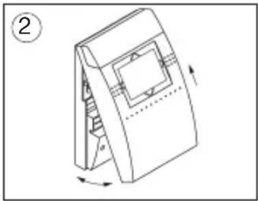
natural_image
Technical line drawing of a mechanical component with rotational arrows indicating motion (no text or symbols)natural_image
Technical line drawing of a mechanical device with a handle and internal components, no text or symbols present
text_image
④ Ø max. 3,5 mmnatural_image
Pure diagram of a circular structure with internal curved elements and no text or symbolsline
| Time | Temperature (°C) | | :--- | :--- | | 6:00 | 17.0 | | 23:00 | 5.0 | | 21.0 | 21.0 | | 17.0 | 17.0 | The chart displays a single data point for temperature at 6:00 and 23:00. The color gradient from light to dark gray indicates the temporal scale of the measured variable.text_image
TEMP+ TEMP3 TEMP2 TEMP1 AUTO OFF TIME HOLI DAY ON/OFF TEMP- TEMP-TEMP+ TEMP-
Temp+/Temp- drücken
text_image
TEMP+ 16.0°C TEMP- TEMP-- Systemeinstellungen
natural_image
Diagram showing a screwdriver inserted into a rectangular component, with an arrow indicating direction (no text or symbols present)
natural_image
Technical line drawing of a mechanical component with rotation arrows (no text or symbols)natural_image
Technical line drawing of a mechanical device with a handle and grid panel (no text or symbols)
text_image
④ Ø max. 3,5 mmnatural_image
Pure electrical circuit lines without any symbolstext_image
TEMP+ TEMP3 TEMP2 TEMP1 AUTO OFF TIME HOLI DAY ON/OFF TEMP- TEMP-TEMP+ TEMP-
Premere Temp+/Temp-
text_image
TEMP+ 16.0°C TEMP- TEMP-7.1 Programmakoppeling 40 - 41
7.2 RESET Ketel 42 - 43
7.3 Communicatiestatus 42 - 43
7.4 Foutmelding Ketel 44
natural_image
Diagram showing a screwdriver inserted into a rectangular component, with an arrow indicating rotation (no text or symbols present)
natural_image
Technical line drawing of a mechanical component with rotation arrows (no text or symbols)natural_image
Technical line drawing of a mechanical device with a handle and grid panel (no text or symbols)
text_image
④ Ø max. 3,5 mm3. Tapwater ON /OFF/AUTO
text_image
TEMP+ TEMP3 TEMP2 TEMP1 AUTO OFF TIME HOLI DAY ON/OFF TEMP- TEMP-Temp+/Temp- drukken
text_image
TEMP+ 146.0°C TEMP- TEMP-7. Systeeminstelling
7.1 Programmakoppeling
Tapwater ON/OFF/AUTO 36-3
-
List of contents
-
List of contents 2 - 3
-
Brief description 4 - 5
2.1 Elementary operator control 6
- Installation 7
3.1 Connecting up 8
- Setting the time/date 9
4.1 Setting summertime/wintertime 10
4.2 nterrogating the current time 11
- Temperature levels 12
5.1 Changing temperature levels 13
6 Overview of programmes and operating modes 14 - 15
6.1 Factory programme P1 16
6.2 Factory programme P 2 17
6.3 Factory programme P 3 18 - 19
6.4 Factory programme P 4 20 - 21
6.5 Selecting factory programme P1 - P4 22
6.6 Selecting / reading the user-defined programme 24 - 25
6.6.1 Entering a user-defined programme 26 - 29
6.6.2 COPY function 30 - 31
- List of contents
3
6.7 AUTO mode 32 - 33
6.8 TEMP 3 mode 34 - 35
6.9 TEMP 2 mode 34 - 35
6.10 TEMP 1 mode 34 - 35
6.11 Service-water operating mode 36 - 37
6.12 HOLIDAY mode 38 - 39
- System settings 40 - 41
7.1 Service-water target temperature 40 - 41
7.2 RESET (gas heater) 42 - 43
7.3 Communication status 42 - 43
7.4 Gas heater (heating boiler) error message 44
-
RESET 45
-
Factory setting 46 - 47
-
Technical data 48
-
Questions and Answers 49
-
Cleaning and maintenance 49
-
Alphabetical subject-index 50 - 51
-
Overview/control elements 52 - 53
-
Overview/displays 54 - 55
Shaded grey area is designed for end-user instruction
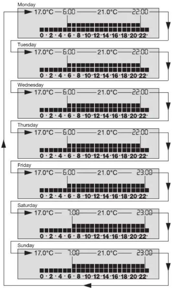
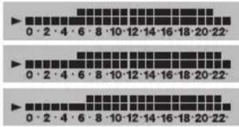
Example: Factory program P1 - weekly overview
text_image
Monday 17.0°C—6:00——21.0°C—22:00 0·2·4·6·8·10·12·14·16·18·20·22 Tuesday 17.0°C—6:00——21.0°C—22:00 0·2·4·6·8·10·12·14·16·18·20·22 Wednesday 17.0°C—6:00——21.0°C—22:00 0·2·4·6·8·10·12·14·16·18·20·22 Thursday 17.0°C—6:00——21.0°C—22:00 0·2·4·6·8·10·12·14·16·18·20·22 Friday 17.0°C—6:00——21.0°C—23:00 0·2·4·6·8·10·12·14·16·18·20·22 Saturday 17.0°C—7:00——21.0°C—23:00 0·2·4·6·8·10·12·14·16·18·20·22 Sunday 17.0°C—7:00——21.0°C—23:00 0·2·4·6·8·10·12·14·16·18·20·222. Brief description
The digital room thermostaat clock OpenTherm operates only in conjunction with gas heaters designed for Open Therm. It is conceivable that certain functions – both of the gas heaters and of the chronostats – are not supported, e.g. privision/heating-up of service water. Refer to the operating instructions for your gas heater to find out whether the provision of service water* is supported. With its various programs, the room thermostat clock Open Therm can control the room temperature according to the relevant requirements. You also set the service water temperature.
Factory programs
The four factory programs are based on the calendar week and are tailored to different living habits.
Individual programs
You can change the four factory programs according to your individual living habits.
AUTOMATIC mode
In this mode, the unit operates:
- Based on one of the four selected factory programs
- Based on the individually set program
Continuous temperature mode
A temperature value is assigned to each of the three mode TEMP 1, TEMP 2 and TEMP 3. If one of these modes is selected, the room temperature is regulated according to this temperature unitl another mode is set.
HOLIDAY mode
This is active for the number of programmed holiday days and then switches back to the programme set before the holiday.
Service water mode
You can set and also switch on/off the service water temperature according to the requirements for the gas heater.
Programming
If you remove the unit from the base and the battery is fully charged (see Technical data for the charging duration), the supply is guaranteed for a certain period.
- approx. five hours if you do not press any buttons
- approx. three hours if you enter / change data
You can enter / change your heating program from the comfort of your armchair.
System data – see Section 7 – can only be set “online”. If no button is pressed within approx. one minute, the display starts to flash. Continue your input with the button PROG or TIME. When entering your heating program, remember that the system requires a certain time to reach the required room temperature. Replace the unit on the base (see Section 3).
* Open Therm is the term for a technology which allows communication to be established between two units with just two lines – communication which can do much more than switch the heating ON and OFF.
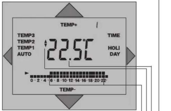
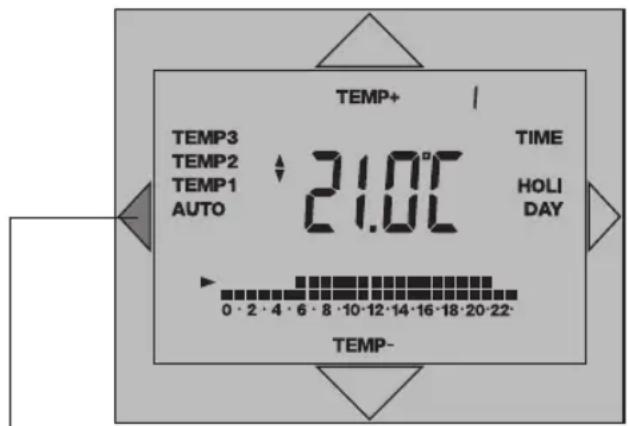
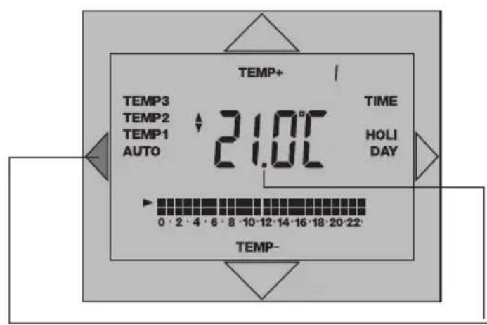
2.1 Elementary operator control
Your chronostat has been installed and the installation technician has programmed the programme of your choice to suit your specific requirements. Proceed as follows if you wish to change the temperature temporarily:
text_image
TEMP+ TEMP3 TEMP2 TEMP1 AUTO 22.5°C TIME HOLIDAY 0 - 2 - 4 - 6 - 8 - 10 - 12 - 14 - 16 - 18 - 20 - 22 - TEMP- TEMP-The display shows the current room temperature
Press the button on the display once and read the programmed temperature
Display for the set room temperature
Press the button on the display and enter the desired temperature
Times for the change in temperature
The symbol „” indicates the switching state „Heating“.
The temperature specified by the programme is reactivated with the next temperature change.
3. Installation
The chronostat must be fitted / installed with an appropriate amount of care by a suitably qualified electrician / technician.
Switch the heating system off before commencing installation!
Notes on the line:
Number of wires 2 / line type not twisted*
Max. line length 50 m / max. line resistance 2 x 5 Ohm
* Electrical interference in the surrounding area can have a negative influence on transfer of information. In such cases we recommend a line with a twisted pair of cores and shielding. See the installation instructions "Gas heaters/boilers"

natural_image
Diagram showing a screwdriver inserted into a rectangular component, with an arrow indicating direction (no text or symbols present)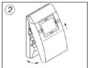
natural_image
Diagram of a mechanical device with a rotating base and internal components, no text or symbols presentLift the chronostat off the stand

natural_image
Diagram of a mechanical device with a handle and grid panel, showing rotational motion (no text or symbols)
text_image
Ø max. 3,5 mm③ Undo the screws Remove the protective housing Be careful not to damage the clips
④ Guide the connecting leads through the cutouts in the stand Mount the stand on a firm surface or a flush type box
3.1 Connecting up
The chronostat must be fitted/installed with an appropriate amount of care by a suitably qualified electrician/technician.
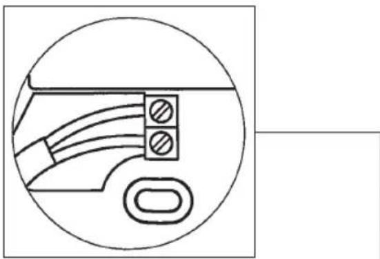
Check and ensure that the connection wires are not conducting any voltage.
text_image
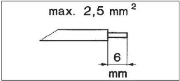
max. 2,5 mm² 6 mmStrip the connecting wires correctly and connect them to the tow connection terminals.
Any connection configuration is possible.
! Reverse polarity protection !
natural_image
Pure electrical circuit lines without any symbolsReplace the protective housing
Be careful not to damage the clips
Tighten the screws
- Setting the time/date 9

text_image
TIME +/-1h PROG. P 1-4 SYS. RES. TIME+ 20:00 *ih DAY TIME- Press the TIME button once The time appears on the display When setting for the first time during summertime, press the +/-1h button once +1h appears on the display Press the button and set the current time Press the button and set the day of the week The days of the week are displayed in the following format: 1=Mo, 2=Tu, 3=We, 4=Th, 5=Fr, 6=Sa, 7=Su Confirm the entered data: Press the TIME button once The unit returns to its AUTOMATIC programme sequence.4.1 Setting summertime/wintertime

text_image
TIME +/-1h PROG. P 1-4 SYS. RES. TIME+ 20:00 +1h DAY TIME- Press the +/-1h button and set summertime / wintertime Displayed indicatorDisplayed indicator
(+1h displayed for summertime; no indicator appears on the display during wintertime (normal time)
Please make sure that +1h is displayed during summertime.
4.2 Interrogating the current time

text_image
TEMP3 TEMP2 TEMP1 AUTO +1h 14:00 TIME HOLIDAY 0 · 2 · 4 · 6 · 8 · 10 · 12 · 14 · 16 · 18 · 20 · 22· TIME Press the TIME button 1x TIME flashes on the display The current time appears on the display The current day of the week appears on the display The display returns to its original state automatically if no buttons are pressed for approx. 8 seconds AUTO Press the AUTO button The units returns to its automatic programme sequence- Temperature levels

text_image
TIME +/-1h PROG. P 1-4 SYS. RES. TEMP+ TEMP3 TEMP2 TEMP1 AUTO 22.5°C TIME HOLIDAY 0·2·4·6·8·10·12·14·16·18·20·22- TEMP- The values below are set at the factory but can be changed as required within these ranges. Factory setting Setting range TEMP 3 21 °C 18° C ... 35 °C TEMP 2 17 °C 14° C ... 20 °C TEMP 1 05 °C 05° C ... 16 °CSee Technical data for frost protection information.
Note: The temperature measuring range between 0°C ... 40°C. If the temperature is outside this range, --: -°C will appear on the display instead of a temperature value.
5.1 Changing temperature levels

text_image
TEMP+ TEMP3 TEMP2 TEMP1 AUTO 21.0°C TIME HOLIDAY 0·2·4·6·8·10·12·14·16·18·20·22 TEMP- Press the AUTO button and select a temperature level TEMP 3 21 °C TEMP 2 17 °C TEMP 1 05 °C (Factory settings) The display starts flashing The programmed temperature appears on the display Press the button and alter the temperature Press the AUTO button - AUTO = automatic programme sequenceNote: Program the temperatures so that TEMP 3 is always higher than TEMP 2 and TEMP 2 is always higher than TEMP 1.
Programs
1. The four factory programs (P 1 - P 4)
The factory programs are based on the calendar week and are tailored to different living habits.
They can be changed as required.
2. Individual programming
You can change the four factory programs according to your individual living habits.
Operation modes:
1. AUTOMATIC
In this mode, the unit operates:
- based on one of the four selected factory programs or
- based on the individually set program
2. Continuous temperature mode
A temperature value is assigned to each of the three mode TEMP 1, TEMP 2 and TEMP 3. If one of these modes is selected, the room temperature is regulated according to this temperature until another mode is set.
3. Service water ON /OFF/AUTO
You can set the service water temperature according to the requirements for the gas heaters (heating boilers) and also switch it to ON/OFF/AUTO.
4. HOLIDAY mode
This mode is active for the number of programmed holiday days and then switches back to the programme set before the holiday.
6. Overview of programmes and operating modes
Factory programme
P 1 Page 16
P 2 Page 17
P 3 Page 18 - 19
P 4 Page 20 - 23
User-defined programme Page 26 - 27
Modes
AUTO mode Page 32 - 33
TEMP 3 mode Page 34 - 35
TEMP 2 mode Page 34 - 35
TEMP 1 mode Page 34 - 35
Service-water ON/OFF/AUTO Page 36 - 37
HOLIDAY mode Page 38 - 39
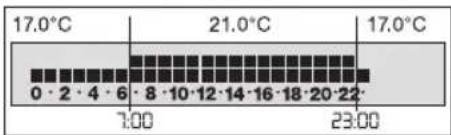
6.1 Factory programme P 1
Factory program P 1 is a daytime and evening programme, i.e. the programme has been designed in such a way that a constant, comfortable temperature prevails during the day and in the evening.
Changing the time and temperature:
Example with factory settings for the temperature levels
TEMP 3 = 21°C
TEMP 2 = 17°C
Monday to Thursday
from 06:00 - 22:00 h TEMP 3
from 22:00 - 06:00 h* TEMP 2
*(the following morning)

from 06:00 - 23:00 h TEMP 3
from 23:00 - 06:00 h* TEMP 2
*(the following morning)

from 07:00 - 23:00 h TEMP 3
from 23:00 - 07:00 h* TEMP 2
*(the following morning)
6.2 Factory programme P 2 17
Factory programme P2 is a full-time working day programme, i.e. the programme has been designed in such a way that a constant, comfortable temperature prevails at breakfast-time, in the evening and all day at the weekend.
Changing the time and temperature:
Example with factory settings for the temperature levels
TEMP 3 = 21°C
TEMP 2 = 17°C
Monday to Friday
from 06:00 - 09:00 h TEMP 3
from 09:00 - 17:00 h TEMP 2
from 17:00 - 22:00 h TEMP 3
from 22:00 - 06:00 h* TEMP 2
*(the following morning, 07:00 h on Saturday)

from 07:00 - 23:00 h TEMP 3
from 23:00 - 07:00 h* TEMP 2
*(the following morning, 06:00 h on Monday)

6.3 Factory programme P 3
Factory programme P3 is a working day programme, i.e. the programme has been designed in such a way that a constant, comfortable temperature prevails at breakfast-time, at lunchtime, in the evening and all day at the weekend.
Changing the time and temperature: Example with factory settings for the temperature levels TEMP 3 = 21°C TEMP 2 = 17°C
Monday to Friday from 06:00 - 08:00 h TEMP 3 from 08:00 - 11:00 h TEMP 2 from 11:00 - 14:00 h TEMP 3 from 14:00 - 17:00 h TEMP 2 from 17:00 - 22:00 h TEMP 3 from 22:00 - 06:00 h* TEMP 2 *(the following morning, 07:00 h on Saturday)
Saturday and Sunday from 07:00 - 23:00 h TEMP 3 from 23:00 - 07:00 h* TEMP 2 *(the following morning, 06:00 h on Monday)

Factory programme P4 is a weekend house programme, i.e. the programme has been designed in such a way that a constant, comfortable temperature prevails during the second half of the day on Friday and all day at the weekend.
Changing the time and temperature: Example with factory settings for the temperature levels TEMP 3 = 21°C TEMP 2 = 17°C TEMP 1 = 05°C
Monday to Thursday TEMP 1 24 hours a day
Friday from 12:00 - 18:00 h TEMP 2 from 18:00 - 23:00 h TEMP 3 from 23:00 - 06:00 h* TEMP 2 *(the following morning)
Saturday from 06:00 - 23:00 h TEMP 3 from 23:00 - 06:00 h* TEMP 2 *(Sunday)
Sunday from 06:00 - 23:00 h TEMP 3 from 23:00 - 12:00 h* TEMP 1 *(Friday)
text_image
TIME +/-1h PROG. P 1-4 SYS. RES. TEMP3 TEMP2 TEMP1 AUTO P1 TIME HOLIDAY 0·2·4·6·8·10·12·14·16·18·20·22·6. 5 Selecting factory programme P 1 - P 4
Press the P 1 - 4 button Select the factory programme of your choice
The selected factory programme appears on the display
The display returns to its original state automatically if no buttons are pressed for approx. 8 seconds
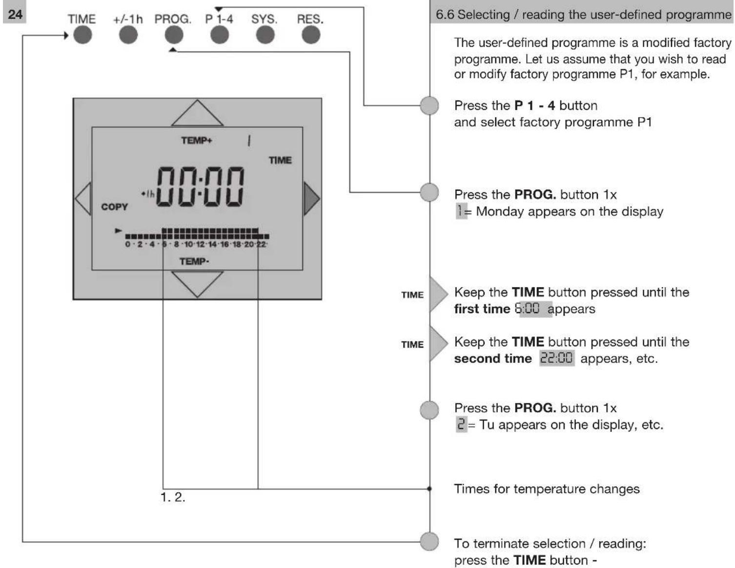
flowchart
graph TD
    A["24"] --> B["TIME"]
    B --> C["+/-1h"]
    C --> D["PROG."]
    D --> E["P 1-4"]
    E --> F["SYS."]
    F --> G["RES."]
    G --> H["6.6 Selecting / reading the user-defined programme"]
    H --> I["The user-defined programme is a modified factory programme. Let us assume that you wish to read or modify factory programme P1, for example."]
    I --> J["Press the P 1 - 4 button and select factory programme P1"]
    J --> K["Press the PROG. button 1x 1 = Monday appears on the display"]
    K --> L["TIME"]
    L --> M["Keep the TIME button pressed until the first time 6:00 appears"]
    M --> N["TIME"]
    N --> O["Keep the TIME button pressed until the second time 22:00 appears, etc."]
    O --> P["Press the PROG. button 1x 2 = Tu appears on the display, etc."]
    P --> Q["Times for temperature changes"]
    Q --> R["To terminate selection / reading: press the TIME button -"]
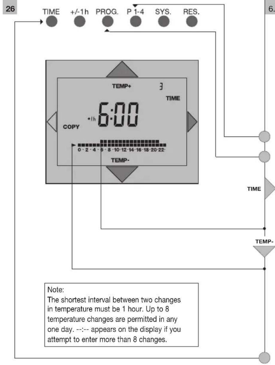
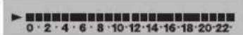
text_image
26 TIME +/-1h PROG. P 1-4 SYS. RES. TEMP+ 3 TIME 6:00 COPY 1h 0:00 0·2·4·5·8·10·12·14·16·18·20·22 TEMP- 6. TIME TEMP- Note: The shortest interval between two changes in temperature must be 1 hour. Up to 8 temperature changes are permitted in any one day. --:-- appears on the display if you attempt to enter more than 8 changes.6.6.1 Entering a user-defined programme
text_image
0·2·4·6·8·10·12·14·16·18·20·22 0·2·4·6·8·10·12·14·16·18·20·22 0·2·4·6·8·10·12·14·16·18·20·22Monday to Thursday Friday Saturday and Sunday
Example:
Adapt the programme (P1) to suit your requirements in the following manner: you wish to lower the temperature to 17^ C for the whole day on Wednesday.
Press the P1 - 4 button until P1 appears on the display
Press the PROG. button 3x
3= We appears on the display
Keep the TIME button pressed until the display stops automatically at 6:00h (temperature change)
The time of the temperature change is displayed
Press the TEMP. button 1x
The arrow moves to the bottom row of little boxes = TEMP 2 = 17°C. The top row of boxes disappears.
Wednesday
The heating system adjusts the temperature to 17^ C until the next temperature change the following morning.

Thursday
To terminate your inputs: press the TIME button

flowchart
graph TD
    A["28"] --> B["TIME"]
    B --> C["+/-1h"]
    C --> D["PROG."]
    D --> E["P 1-4"]
    E --> F["SYS."]
    F --> G["RES."]
    G --> H["6.6.1 Entering a user-defined programme 29"]

    subgraph Time
        I["0·2·4·6·8·10·12·14·16·18·20·22"] --> J["TIME"]
        K["0·2·4·6·8·10·12·14·16·18·20·22"] --> L["PROG. button 5x"]
        M["0·2·4·6·8·10·12·14·16·18·20·22"] --> N["PROG. button 5x"]
    end

    subgraph Time
        O["0·2·4·6·8·10·12·14·16·18·20·22"] --> P["TIME"]
        Q["0·2·4·6·8·10·12·14·16·18·20·22"] --> R["PROG. button 5x"]
        S["0·2·4·6·8·10·12·14·16·18·20·22"] --> T["PROG. button 5x"]
    end

    subgraph Time
        U["0·2·4·6·8·10·12·14·16·18·20·22"] --> V["TIME"]
        W["0·2·4·6·8·10·12·14·16·18·20·22"] --> X["PROG. button 5x"]
        Y["0·2·4·6·8·10·12·14·16·18·20·22"] --> Z["PROG. button 5x"]
    end

    subgraph Time
        AA["0·2·4·6·8·10·12·14·16·18·20·22"] --> AB["TIME"]
        AC["0·2·4·6·8·10·12·14·16·18·20·22"] --> AD["PROG. button 5x"]
        AE["0·2·4·6·8·10·12·14·16·18·20·22"] --> AF["PROG. button 5x"]
    end

    subgraph Time
        AG["0.3h 17:00"]
        AH["Time Period 17:00"] --> AI["Press the P1 - 4 button until P1 appears on the display"]
        AJ["Time Period 17:00"] --> AK["Press the PROG. button 5x"]
        AL["Time Period 17:00"] --> AM["Keep the TIME button pressed until the time 17:00 appears on the display"]
        AN["Time Period 17:00"] --> AO["Press the TIME button 1x"]
        AP["Time Period 17:00"] --> AQ["Press the TIME button 1x"]
        AR["Time Period 17:00"] --> AS["Press the TIME button 1x"]
        AT["Time Period 17:00"] --> AU["Press the TIME button 1x"]
        AV["Time Period 17:00"] --> AW["Press the TIME button 1x"]
        AX["Time Period 17:00"] --> AY["Press the TIME button 1x"]
        AZ["Time Period 17:00"] --> BA["Press the TIME button 1x"]
        BB["Time Period 17:00"] --> BC["Press the TIME button 1x"]
        BD["Time Period 17:00"] --> BE["Press the TIME button 1x"]
        BF["Time Period 17:00"] --> BG["Press the TIME button 1x"]
        BH["Time Period 17:00"] --> BI["Press the TIME button 1x"]
        BJ["Time Period 17:00"] --> BK["Press the TIME button 1x"]
        BL["Time Period 17:00"] --> BM["Press the TIME button 1x"]
        BN["Time Period 17:00"] --> BO["Press the TIME button 1x"]
        BP["Time Period 17:00"] --> BQ["Press the TIME button 1x"]
        BR["Time Period 17:00"] --> BS["Press the TIME button 1x"]
        BT["Time Period 17:00"] --> BU["Press the TIME button 1x"]
        BV["Time Period 17:00"] --> BW["Press the TIME button 1x"]
        BX["Time Period 17:00"] --> BY["Press the TIME button 1x"]
        BZ["Time Period 17:00"] --> BQ
        CA["Time Period 17:00"] --> BQ
        CB["Time Period 17:00"] --> BQ
    end
TIME
+/-1h
PROG.
P 1-4
SYS.
RES.

Press the PROG button
Example:
You have programmed day 1
If you wish to adopt the same daily programme for subsequent days, press the
COPYbutton
COPY day 1 to day 2 - COPY to day 3, etc.
The selected day appears on the display
Note:
Bear in mind that the last temperature programmed for the copied day continues to apply until a different temperature is programmed on one of the following days. Always check the entered programme day by day, as described in Page 20.
Press the TIME button
The unit returns to its automatic programme sequence.
text_image
TEMP+ TEMP3 TEMP2 TEMP1 AUTO 21.0°C TIME HOLIDAY 0·2·4·6·8·10·12·14·16·18·20·22- TEMP-6.7 AUTO mode 33
The chronostat operates in accordance with one of the four factory programmes or the user-defined program in this mode
AUTO Press the AUTO button
Display
Selected
mode
AUTO flashes on the display
text_image
TEMP+ TEMP3 TEMP2 TEMP1 AUTO 21.0°C TIME HOLI DAY TEMP- 0 - 2 - 4 - 6 - 8 - 10 - 12 - 14 - 16 - 18 - 20 - 226.8 TEMP 3 mode
6.9 TEMP 2 mode
6.10 TEMP 1 mode
A single temperature is assigned to each of the continuous temperature modes. The programmed temperature is maintained until another mode is selected.
AUTO Press the AUTO button and select a temperature level TEMP3 21 °C
TEMP2 17 °C
TEMP1 5 °C
(Factory settings)
Display Selected mode
Example:
TEMP 3 flashes on the display
Display
Shows the set temperature Example:
21.0°C
The current room temperature is displayed after approx. 8 seconds
If you wish to return to the automatic programme sequence:
AUTO press the AUTO button until AUTO starts flashing on the display
6.11 Service-water operating mode
Check in the operating manual of your gas heater as to whether the provision of service water* is supported.
The + symbol indicates the „Service Water ON“ function.
The 🔔 symbol indicates when the gas heater is actually heating.
Note: If the gas heater does not support the provision of service water, then no corresponding symbols/menu items are displayed.
Service water OFF/ON/AUTO (OFF/ON/AUTO)

OFF/ON/AUTO (OFF/ON/AUTO)
This selection offers you:
ON = Continuous ON/service water supply is switched ON +
OFF = Continuous OFF/service water supply is switched OFF
AUTO = Automatic mode/program connection
In this operating mode, heating of the service water is specified as follows:
- At the first switching time of the current day on which the heating switches to TEMP3, the service water supply is also switched ON.
- At the last switching time of the current day on which the heating switches from TEMP3 to TEMP2 or to TEMP1, the service water supply is switched OFF again.

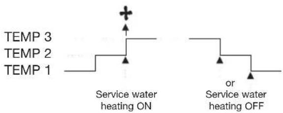
text_image
TEMP 3 TEMP 2 TEMP 1 Service water heating ON or Service water heating OFF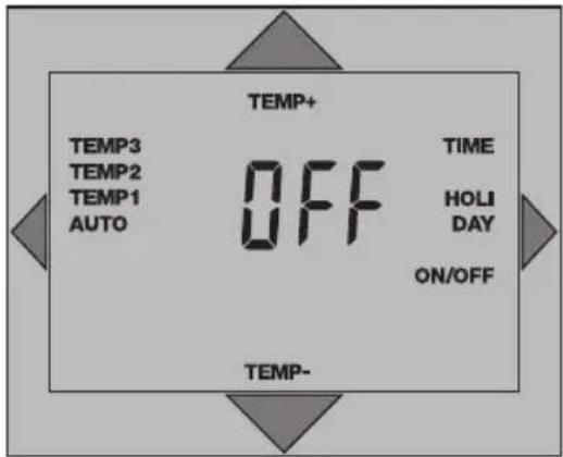
text_image
TEMP+ TEMP3 TEMP2 TEMP1 AUTO OFF TIME HOLI DAY ON/OFF TEMP- TEMP-Press Temp+/Temp-
The switching state OFF/ON or AUTO is displayed.
ON = Service water ON
OFF = Service water OFF
AUTO = Service water automatic mode/program connection
If no further keys are pressed, the current room temperature is displayed after approx. 8 seconds.
* The service water is heated in accordance with the set target value. The min. and max. target value (temperature), e.g. min. 40 °C, max. 60 °C, are determined by the gas heater (heating boiler). This means that you can only set a temperature within this range. For the target service-water temperature, see Section 7.1.

text_image
TEMP+ AUTO HOLIDAY TEMP-6.12 HOLIDAY mode 39
In this mode, the unit switches to Temperature level 1 (factory setting +5 °C) and is active for the programmed number of holiday days. After the programmed number of holiday days has expired, the unit switches back to the automatic programme sequence.
HOLI DAY
Press the HOLIDAY button 3x
HOLI DAY
HOLIDAY starts flashing on the display
The first day of the holiday period appears on the display
Example: Press the HOLIDAY button 1x = 2 days holiday.
TEMP+ TEMP-
Press the ... button and select the temperature
To terminate HOLIDAY mode prematurely: AUTO press the AUTO button The unit returns to the automatic programme sequence

text_image
TIME +/-1h PROG. P 1-4 SYS. RES.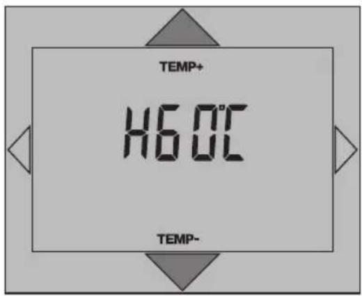
text_image
TEMP+ 16.0°C TEMP- TEMP-7. System Settings
7.1 Service-water target temperature
Check in the operating manual of your gas heater as to whether the provision of service water* is supported.
Note: If the gas heater does not support the provision of service water, then no corresponding symbols/menu items are displayed. With certain types of gas heaters it is not possible to adjust the service-water target temperature via the room thermostat-clock. The preset value can only be read.
Press SYS. button 1x
For example, the display indicates H60°C (as shown in display).
Set target value:
TEMP+ = Increase temperature
TEMP- = Decrease temperature
TEMP+ TEMP-
Press button and change temperature.

text_image
TIME +/-1h PROG. P 1-4 SYS. RES. HEAL RES7.2 RESET (gas heater)
If the gas heater (heating boiler) supports this function, it can be set to a defined state from the room thermostat-clock in the case of an error message (see Section 7.4).
Press the SYS. button again
The display shows HERE (as shown in display). Press Res; the gas heater is set to a defined state.
* The service water is heated in accordance with the set target value. The min. and max. target value (temperature), e.g. min. 40 °C, max. 60 °C, are determined by the gas heater (heating boiler). You can only set a temperature within this range. For information on the service-water operating mode, see Section 6.11.
7.3 Communication status
Press the SYS. button again
The display shows:
$$ \begin{array}{r l} \text { Ot:P } & = \text { Communication OK } \ & (\text { OpenTherm plus }) \end{array} $$
or
$$ \begin{array}{r l} \text { O t : } & = \text { C o m m u n i c a t i o n n o t O K } \ & (\text { O p e n T h e r m p l u s }) \end{array} $$
When communication with OpenTherm light takes place, there is no display at this point.
44 7.4 Gas heater (heating boiler) error message

text_image
TIME +/-1h PROG. P 1-4 SYS. RES. 00:33If the gas heater reports an error or communication is defective, the display of the room thermometer-clock flashes. It flashes until the error is eliminated.
(For information on resetting the gas heater, see 7.2)
You can read the error message with the SYS. button. It is displayed as a four-digit number. See the operating manual of your gas heater for the meaning of the displayed error code (only the two numbers on the right).
Read error message
Press the SYS. button 1x
The error code is displayed as a four-digit number
8. RESET
8.1 Room thermostat-clock

text_image
TIME +/-1h PROG. P 1-4 SYS. RES. TIME+ 20:00 DAY TIME-The unit is set to a defined state. The time is set to Monday, 8 p.m.
Reset the room thermostat-clock
Press the RES. button
Communication between the room thermostat-clock and the gas heater (heating boiler) is restored. This may take a few seconds in some cases.
To set the time/day of the week, see Section 4.
8.2 Gas heater
See Section 7.2
If no further keys are pressed, the current room temperature is displayed after approx.
8 seconds.
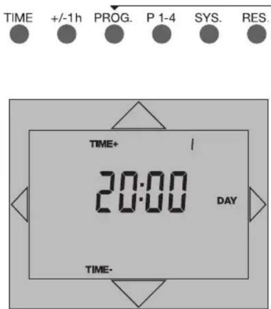
text_image
TIME +/-1h PROG. P 1-4 SYS. RES. TIME+ 20:00 DAY TIME-9. Recalling the factory settings
This function recalls factory programmes P1 - 4 and the factory settings for the temperature levels and resets the current time to Monday 20:00 h. It also erases all user-defined settings.
Press the PROG. button and keep it pressed
Press the RES. button
Release the RES. button
Release the PROG. press down key until 20:00 h appears in the display
Press the TIME 1x
Selecting factory programmes 6.1 or Entering a user-defined programme
10. Technical data
Dimensions H x W x D (mm) 134 x 81 x 33
Weight approx. 200g
Operating voltage System voltage
Ambient temperature - 5 °C to + 45 °C
Protection class II
Accuracy typ 2,5 s/day at +25 °C
Running reserve 5 h
Ladedauer 24 h
Shortest switching period:
- daily program 1 h
- weekly program 1 h
Programmable every 15 min
Switching preselection yes
Switching state display and operating modes:
Heating mode Flame symbol
Service-water Symbol
Automatic mode AUTO
Continuous mode TEMP1, TEMP 2 or TEMP 3
Holiday mode HOLIDAY
Type of installation Surface-mounted
Connection type Screw-type terminals, each 2,5 mm ^4
Temperature Heating control range + 5 °C to + 35 °C
Protection against freezing TEMP 1 setting (factory setting: 5°C)
Differential temperature gap + / - 0,25 at 0,4 K *
Degree of protection IP 20
11. Questions and Answers
Questions:
The unit does not work
- no display
- no heating operation
Answers:
Check the connection see Section 3.1
Press RES. if necessary see Section 7.4
Questions:
It is not possible to set the value for the temperature level
Answers:
Select values within the setting range see Abschnitt 6.1 ff
Questions:
The wrong key has been pressed or incorrect values have been entered during programming.
Answers:
Cancel the operation: Repeat the complete programming sequence.
12. Cleaning and maintenance
Use a dry cloth to clean the unit.
Never use any caustic cleaning agents.
13. Alphabetical subject-index
Key word page
Adjust service water temperature 37
Arrow keys 52-53
Assembly 07
AUTO automatic programme sequence 53
Basic programs 04-05
Brief description 05
Cleaning and maintenance 49
Control elements 52-53
Connecting up 08
Continuous temperatures 34-35
Copy function 30-31
Communication status 42-43
Delete settings 44
Display 52-53
Displays 54-55
Elementary operator control 06
Enter/change program 26-27
Enter day of the week 09
Error message, gas heaters 44
Factory programs 16-23
Factory settings 12/15/45
Frost protection 12
Holiday mode 38-39
Individual program 24-25
Installation 07
Interrogating the time 11
Keys 52-53
OpenTherm 05
Overview 54-55
Key word page
Programme coupling 36
Questions and answers 49
RES gas heaters 43/53
RESET room thermostats 43
Room temperature 34
Service 31
Service water ON/OFF/AUTO 36-37
Setting the time 09
Summer time 10
System settings 40-44
Technical data 48
TEMP 52-53
Temperature levels 12
TIME display 54-55
Unit stand 07
Winter time 10

text_image
TIME +/-1h PROG. P 1-4 SYS. RES.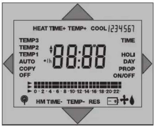
text_image
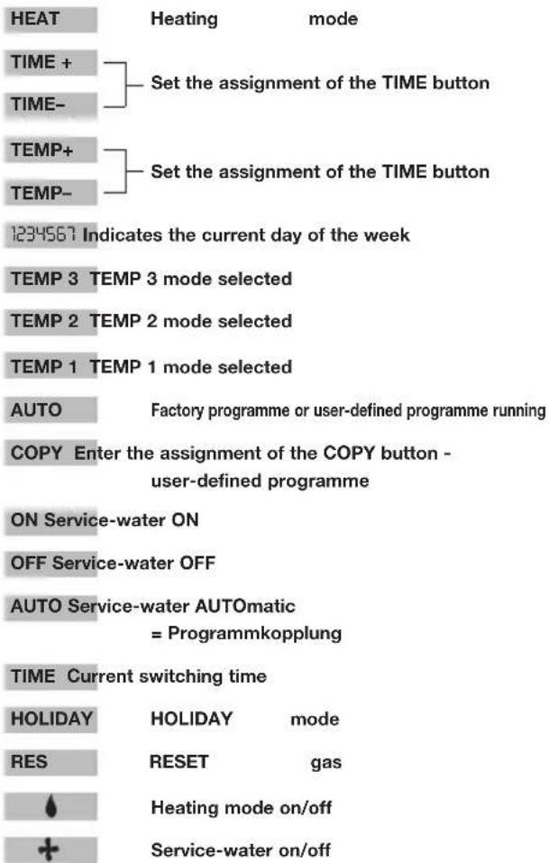
HEAT TIME+ TEMP+ COOL 1234567 TEMP3 TEMP2 TEMP1 AUTO COPY OFF 88:00 TIME HOLI DAY PROP ON/OFF 0 · 2 · 4 · 6 · 8 · 10 · 12 · 14 · 16 · 18 · 20 · 22· HM TIME- TEMP- RES - + +- Overview / control elements
| TIME | Setting the current time Confirming inputs |
| +/- 1h | Setting and changing over between summertime and wintertime |
| PROG. | Recalling, reading and editing the programme |
| P 1-4 | Selecting the factory programmes |
| SYS. | System settings |
| RES. | Reset to a defined operating state, time Mo 20:00 h |
| Setting the temperature / time Selecting temperature level / system setting | |
| Setting the temperature / time Selecting temperature level Resetting the elapsed-hour meter | |
| Selecting the operating mode: TEMP 1, TEMP 2, TEMP 3, AUTO, COPY | |
| Interrogating the current time Selecting the PARTY and HOLIDAY modes System settings Selecting the times for temperature changes |


text_image
HEAT TIME+ TEMP+ COOL 1234567 TEMP3 TEMP2 TEMP1 AUTO COPY OFF 88:00 TIME HOLI DAY PROP ON/OFF 0 · 2 · 4 · 6 · 8 · 10 · 12 · 14 · 16 · 18 · 20 · 22· HM TIME- TEMP- RES Switching programme in hours Current temperature level Temperature / time / prog. Summertime Changing the required value15. Overview / displays