Famoso 500 - Thermostat Grässlin - Free user manual and instructions
Find the device manual for free Famoso 500 Grässlin in PDF.

User questions about Famoso 500 Grässlin
0 question about this device. Answer the ones you know or ask your own.
Ask a new question about this device
Download the instructions for your Thermostat in PDF format for free! Find your manual Famoso 500 - Grässlin and take your electronic device back in hand. On this page are published all the documents necessary for the use of your device. Famoso 500 by Grässlin.
USER MANUAL Famoso 500 Grässlin
text_image
5° 1 2 5° 30°C 30°CD Bedienungsanleitung
GB Operating Instructions
F Mode d'emploi
I Instruzioni d'uso
E Instrucciones de empleo
NL Gebruiksaanwijzing
1. Inhaltsangabe 2
text_image
Diagram of a rotary device with labeled parts and control buttons, showing dial, clock, and indicator lights.
text_image
1 2 3 4 5 6 7 8 9 10 11 12 13 14 15 16 17 18 19 20 21 22 23 24 25 26 27 28 29 30 31 32 33 34 35 36 37 38 39 40 41 42 43 44 45 46 47 48 49 50 51 52 53 54 55 56 57 58 59 60 61 62 63 64 65 66 67 68 69 70 71 72 73 74 75 76 77 78 79 80text_image
Warning symbol image with exclamation mark inside triangle
text_image
Electronic
text_image
AC ~natural_image
Technical line drawing of a mechanical device with rotating components and directional arrows indicating motion (no text or symbols)text_image
Diagram showing electrical circuit components with screw and iron symbols, including a switch and power sourcenatural_image
Simple electrical circuit diagram with three labeled terminals (③, ④, ⑤) and a switch symbol between terminals (no text or numerical labels)natural_image
Diagram of a battery cell with internal components and directional arrows indicating flow or movement (no text or symbols)
Hinweis:
text_image
Technical diagram showing a device with a top panel and a bottom panel, both labeled with numerical indicators and an upward arrow.text_image
Diagram showing a clock with hour and minute hands, including a separate watch and a circular dial with time markings.Wochenschaltuhr
1 Segment = 1 Stunde
text_image
Diagram of a temperature sensor or display panel with labeled components and indicators
text_image
Technical diagram of an electronic device with labeled ports and indicators, including a thermometer and indicator lights.text_image
888.0°C + +1 +2
text_image
000.0°C +1200.0°C1. List of contents 2
-
List of contents Page
-
Elementary operator control 3
-
Installation 4
3.1 Connecting up 4
3.2 Fitting/replacing the battery 5
-
Setting the correct time 6
-
Setting the switching times 7
-
Setting the temperature levels 8
-
Manual switch/operating modes 8
-
Heating cycle setting 9
-
Reset 10
-
Technical data 10
-
Problems and remedies 11
-
Cleaning and maintenance 11
-
Alphabetical subject-index 11
Grey area indicates user range

text_image
Diagram of a rotary device with labeled parts and control buttons, showing dial, clock, and indicator lights.
text_image
1 2 3 4 5 6 7 8 9 10 11 12 13 14 15 16 17 18 19 20 21 22 23 24 25 26 27 28 29 30 31 32 33 34 35 36 37 38 39 40 41 42 43 44 45 46 47 48 49 50 51 52 53 54 55 56 57 58 59 60 61 62 63 64 65 66 67 68 69 70 71 72 73 74 75 76 77 78 79 80This room thermostat clock creates comfortable room temperatures in the simplest way possible.
The two temperature levels
$$ \begin{array}{l} Ⓦ 1 = \text { Comfort temperature } \ Ⓠ _ {2} = \text { Lower temperature } \ \end{array} $$
are set with the according knobs.
Settings between 5°C and 32°C possible.
The manual switch can be used to switch between three operating modes:
Operating mode = Automatic
The unit operates during the set switching times and switches between _1 and _2 .
Continuous temperature operating modes
$$ \begin{array}{l} ⓚ _ {1} = \text { Comfort temperature } \ Ⓦ _ {2} = \text { Lower temperature } \ \end{array} $$
The selected temperature remains constant until a different operating mode has been selected.
Please remember when setting the switching times that the heating system requires a certain amount of time before it reaches the desired temperature.
3. Installation
Open the battery compartment lid and release the catch
text_image
90°Remove the room thermostat clock from its base

natural_image
Technical line drawing of a mechanical device with rotating components and directional arrows indicating motion (no text or symbols)Feed the connection wires through the opening in the unit's base
Attach the base on a firm surface or surface-mounted socket

text_image
Diagram showing electrical circuit components with screw and iron symbols, including a switch and power source3.1 Connecting up 4
The unit must be connected by a qualifeid person exercising due care.
Check and make sure that the connecting wires are not live.
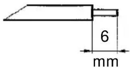
Strip the connection wires properly and connect as shown in the circuit diagram.
max. 2,5 mm ^4
text_image
6 mmContacts 4-5 closed = heating mode

natural_image
Simple electrical circuit diagram with three labeled terminals (③, ④, ⑤) and a switch symbol between terminals (no text or numerical labels)Place the room thermostat clock on its base and resecure

text_image
90°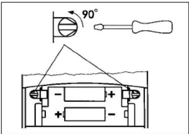
text_image
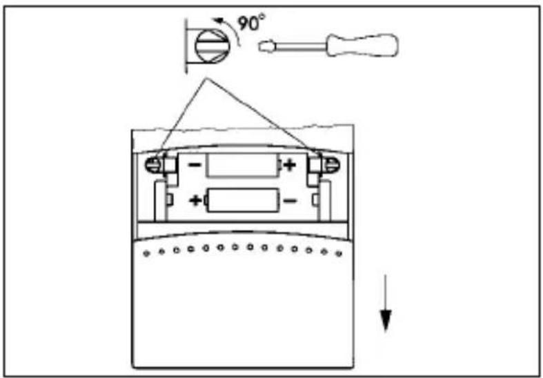
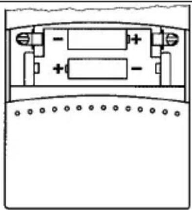
90°3.2 Fitting/replacing the batteries
Open the battery compartment lid
Fit the batteries
Battery type LR6/AA (2 batteries)
Only fit alkaline batteries
Close the battery compartment lid
natural_image
Pure electrical circuit lines without any symbols

Note:
If the actual temperature is not displayed after the batteries have been changed, press the „Reset“ button, see page 10
3.2 Fitting/replacing the batteries 5
Battery symbol is displayed
Change batteries immediately. Otherwise safe functioning is not guaranteed.
The entered data will not be erased when the batteries are changed.

text_image
1 2
Note:
The unit measures the battery voltage when switching on and off. The battery display will not change if no switching occurs.
4. Setting the correct time/weekday
Slide the cover upwards and remove.

text_image
Technical diagram showing a device with a circular dial and its analog scale, including an upward arrow indicating motion or adjustment.4. Setting the correct time/weekday

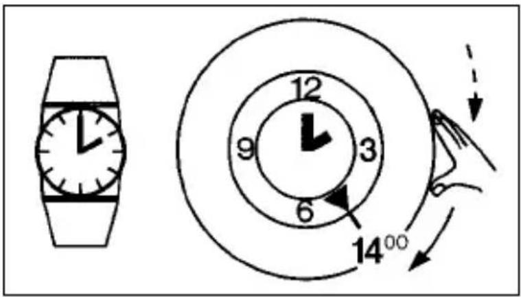
Only turn in the direction of the arrow

Day time switch
e. g. 14.00 h
Turn the ring in the direction of the arrow until the desired hour is aligned with the locating arrow.
The precise setting is made with the minute hand.
text_image
Diagram showing a clock with hour and minute hands, including a separate watch and a circular dial with time markings.Week time switch
e. g. Tuesday 14.00 h
Turn the ring in the direction of the arrow until the desired week day is in the area of the locating arrow.
The precise setting is made with the minute hand.

text_image
Sa Fr 12 So 9 3 6 Mo 14°00 Do M S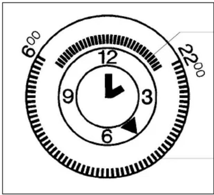
text_image
6°00 12 9 3 6 22°00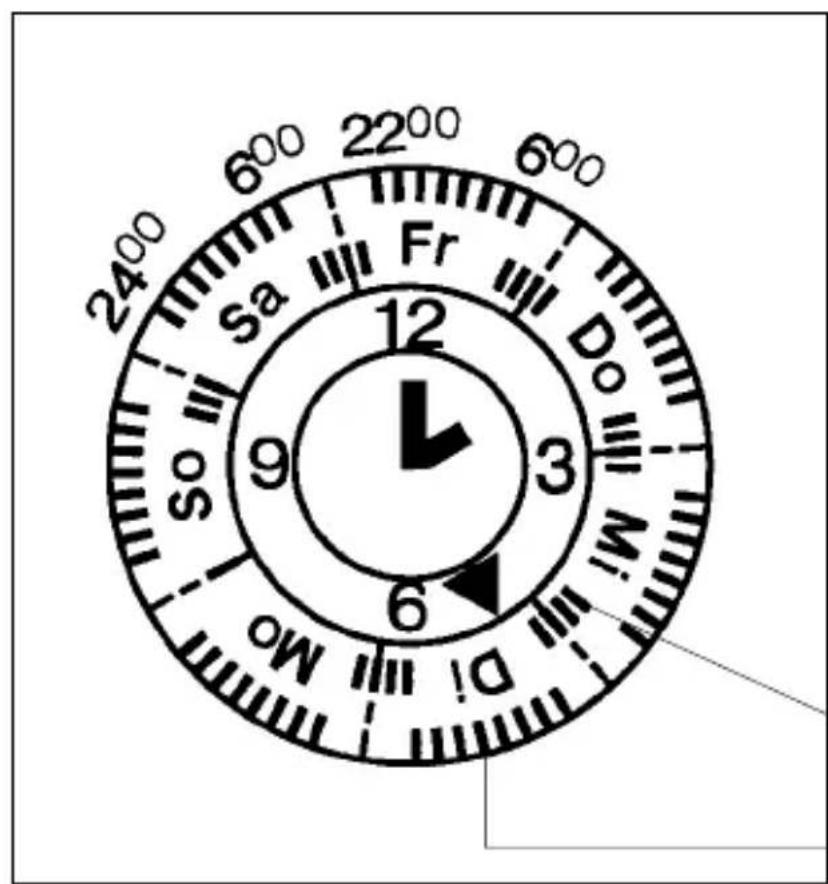
text_image
2400 600 2200 600 Sa Fr Do M.I 12 9 3 6 So Mo5.1 Switching times for changing temperatures with the day time switch
e. g. 06.00 - 22.00 Uhours = Comfort-temperature
e. g. 22.00 - 06.00 hours = Lower temperature
Inside segments = Lower temperature
Outside segments = Comfort- temperature
1 segment = 15 minutes


5.2 Switching times for changing temperatures with the week time switch
e. g. Monday - Friday
06.00 - 22.00 h = Comfort- temperature
22.00 - 06.00 h = Lower temperature
Saturday - Sunday
06.00 - 24.00 h = Comfort- temperature
24.00 - 06.00 h = Lower temperature
Inside segments = Lower temperature
Outside segments = Comfort- temperature
1 segment = 1 hour


6. Switching the temperatures on/off
The two temperature values – desired temperatures are set independently of each other.
Adjustable by 0,5°C steps between 5°C and 32°C.
The last displayed desired value is stored.
Comfort
temperature
e. g. +22°C
(Factory setting 21°C)
Lower
temperature
e. g. +15°C
(Factory setting 15°C)

text_image
Diagram of a temperature sensor or display panel with labeled components and indicators
text_image
Technical diagram of a device panel with labeled ports and indicators, including temperature sensors and control buttons.Comfort
temperature
e. g. +22°C
(Factory setting 21°C)
Lower
temperature
e. g. +15°C
(Factory setting 15°C)
After approx. 4 seconds, the unit switches into the current state: actual temperature

Protection from frost is guaranteed in any event because no settings below 5°C are possible.
7. Manual switch/operating modes

text_image
F1 F2 12 9 3 6 F1 F2The manual switch selects one of three operating modes:
Operating mode = Automatic
The unit operates during the set times and switches between _1 and _2 .
Continuous temperature operating modes
$$ \begin{array}{l} Ⓦ _ {1} = \text { Comfort temperature } \ Ⓦ _ {2} = \text { Lower temperature } \ \end{array} $$
The selected temperature remains until a different operating mode is selected.
text_image
1 2 0 4The heating-cycle setting (CDF value) is for adapting to the control range.
This is affected by:
- Room size
- Type of heating, e. g. convectors, storey heating
- T ype of assembly
- T emperature control/thermostat
The set value can be altered to achieve an optimum heating control.
The set value from 1 to 6. If the room-temperature change is too great (e.g. caused by ventilation), the cycle time can be prematurely ended or the unit can be re-activated.
If the temperature difference in the room is too great, the system switches ON and OFF too infrequently.
This means that the CDF value must be reduced.
If the system switches too frequently, a higher CDF value must be selected accordingly.
Factory setting CDF = 4
8.1 Heating cycle setting/assembly 9
Recommended settings Set value
Direct electric heating 1 or 2
Supplementary electric 2 or 3 bathroom radiator
Single-room control system 3 or 4 with electrically operated radiator valves (hot-water heating)
Small or medium-sized rooms
Single-room control system 4 or 5 with electrically operated radiator valves (hot-water heating)
Medium-sized or large rooms
Wall-mounted gas-fired boiler 4 or 5 for single-storey heating systems
Free-standing gas-fired boiler 4,5 or 6 or oil-fired boiler for larger living modules
| Set value | 1 | 2 | 3 | 4 | 5 | 6 |
| Cycle time1x ON - 1x OFFin minutes | 48,51 | 317 | 21 | 25,5 |
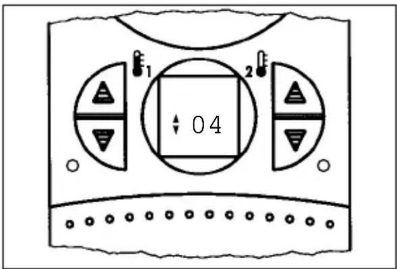
Press the 1x button with a pencil or similar object

text_image
04
text_image
1 2 : 04Read CDF value
Press the button several times Change the setting
After approx. 8 seconds, the display will return to its original status.
The last value set is stored.
9. Reset
The unit is put into a defined operating status with reset.
The set temperature values and the CDF setting are maintained
Press this button once with a pencil or similar object

text_image
888.0°C +12.0E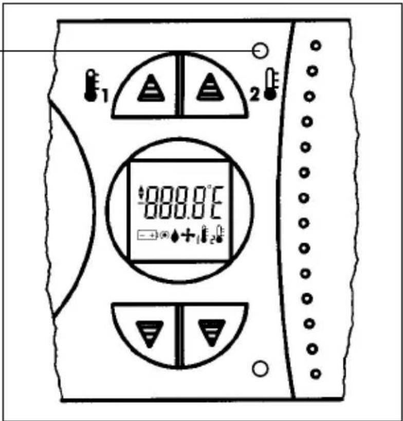
text_image
1 2 888.0°C +12The room temperature is displayed after approx. 8 seconds.
Dimensions H x W x D (mm) 158 x 75 x 36,5
Operating voltage battery, type LR6/AA (2 batteries). Only fit alkaline batteries
Switching capacity
- at ohmic loads 5 A/250 V\~
- at inductive loads 1 A/250 V\~cos φ 0,6
- min. 1 mA at 24 V DC
Switching output floating
Switching contact 1 changeover contact
Ambient temperature -5^ +45^
Class of protection II
Accuracy ±2,5 s/day at +25°C
Battery life approx. 1 year
Shortest switching period
– daily programme 15 min.
- weekley programme 2 h, settings by hours
Operating modes


Automatic mode

Comfort temperature
Lower temperature

Comfort temperature continuous mode

Lower temperature continuous mode
Temperature regulation range +5°C to +32°C
Temperature switching difference ±0,25 ... 0,5 K*
Regulator digital
Degree of protection IP 20
* Greater fluctuations are possible as a result of the heating system and the heated room
Problems:
Restricted operation and function.
The symbol - + appears in the display.
Remedy:
Change batteries 5
Only fit alkaline batteries
Problems:
The room is too hot or cold
Remedy:
Check temperature settings 8
Problems:
The heating system does not switch on or off on time
Remedy:
Check time and switching time 6 / 7
Problems:
The heating system does not switch on or off
Remedy:
Check the manual switch 8
Unit is switched to continuous mode
Problems:
The heating system takes too long to reach the desired temperature. The heating system switches too frequently.
Remedy:
Check heating-cycle setting 9
correct if necessary
Problems:
□□□□/□□□□ appears in the display
The ambient temperature is lower or higher
than the temperature measuring range
Remedy:
Adapt ambient temperature, e. g. prevent exposure to direct sunlight.
12. Cleaning and maintenance 11
Use a dry cloth to clean the unit.
Never use any caustic cleaning agents.
13. Alphabetical subject-index
Key word Page
Automatic mode 3 / 5
Battery 4
CDF value 9 / 10
Cleaning and maintenance 8
Connections 4
Continuous temperatures 3 / 5
Cycle times 6
Diagram 4
Elementary operator control 3
Entering/editing programme 5
Factory settings 5 / 6
Faults 8
Frost protection 5
Heating mode 3 / 5
Heating-cycle setting
Heating-systems
Installation 4
Power supply 4
Problems and remedies 8
Programme setting 6
Reset 7
Room temperature 3 / 5
Setting switching times 5
Setting the current time 6
System settings 6
Technical data 7
Temperature levels 5
Time setting 4
Unit base 4
1. Sommaire 2
text_image
Diagram of a rotary device with labeled parts and control buttons, showing dial, clock, and indicator lights.
text_image
1 2 3 4 5 6 7 8 9 10 11 12 13 14 15 16 17 18 19 20 21 22 23 24 25 26 27 28 29 30 31 32 33 34 35 36 37 38 39 40 41 42 43 44 45 46 47 48 49 50 51 52 53 54 55 56 57 58 59 60 61 62 63 64 65 66 67 68 69 70 71 72 73 74 75 76 77 78 79 80natural_image
Technical line drawing of a mechanical device with directional arrows indicating motion (no text or symbols)text_image
Diagram showing electrical circuit components with screw and iron symbols, including a switch and battery pack3.1 Raccordement 4
natural_image
Simple electrical circuit diagram with three labeled terminals (③, ④, ⑤) and a switch symbol between terminals (no text or numerical labels)natural_image
Diagram of a battery cell with internal components and directional arrows indicating flow or movement (no text or symbols)
text_image
Technical diagram showing a device with a top panel and a bottom panel, both labeled with numerical indicators and an upward arrow.1 Segment = 15 minutes
text_image
Diagram of a temperature sensor or display panel with labeled components and indicators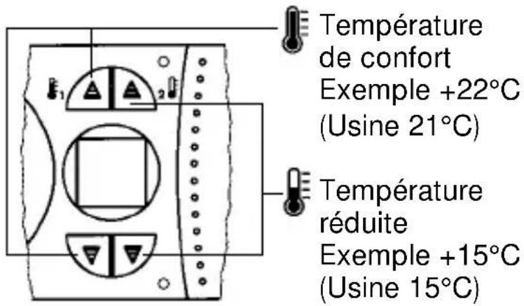
text_image
899.8℃ + +1 E2 E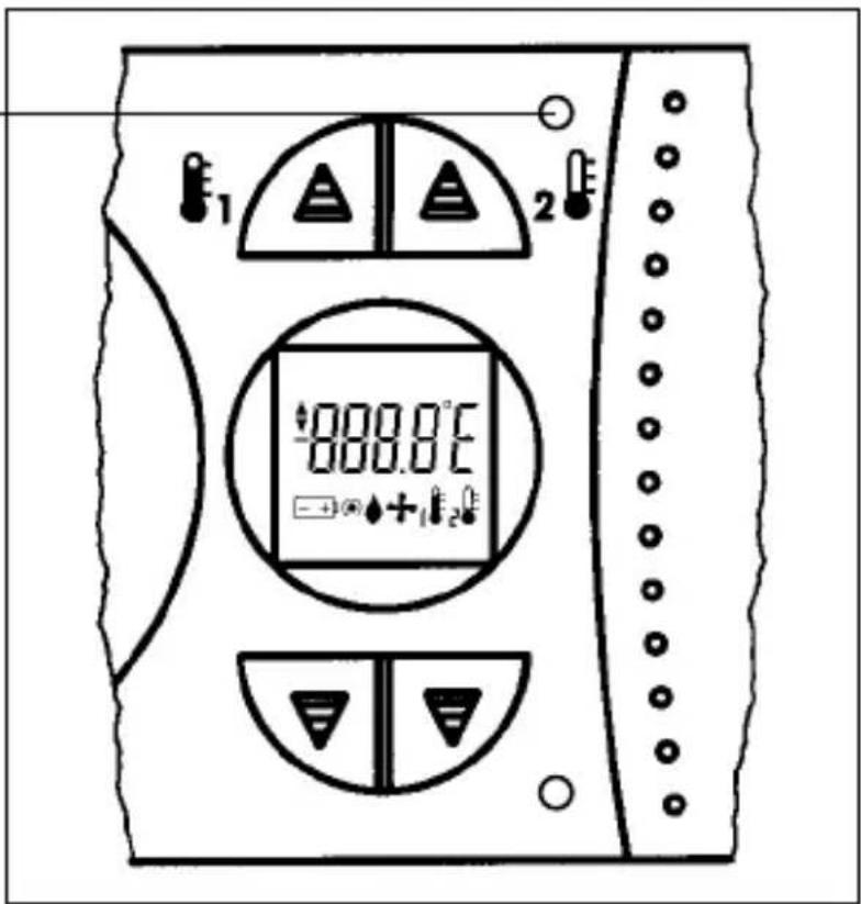
text_image
000.0°C +1200.0°C(non fournies). Utilizer
seulements des
piles alcalines
Pouvoir de coupure
text_image
Diagram of a rotary device with labeled parts and circular dial indicators
text_image
1 2 3 4 5 6 7 8 9 10 11 12 13 14 15 16 17 18 19 20 21 22 23 24 25 26 27 28 29 30 31 32 33 34 35 36 37 38 39 40 41 42 43 44 45 46 47 48 49 50 51 52 53 54 55 56 57 58 59 60 61 62 63 64 65 66 67 68 69 70 71 72 73 74 75 76 77 78 79 80natural_image
Technical line drawing of a mechanical device with directional arrows indicating motion (no text or symbols)text_image
Diagram showing electrical connections with screw and iron components, including a device panel and grounding symbols3.1 Collegamento 4
natural_image
Simple electrical circuit diagram with three labeled terminals (③, ④, ⑤) and a switch symbol between terminals (no text or numerical labels)natural_image
Pure electrical circuit lines without any symbols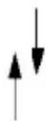

Avvertenza:
text_image
Technical diagram showing a device with a top panel and a bottom panel, both labeled with numerical indicators and an upward arrow.
text_image
Diagram showing a clock with hour and minute hands, including a separate watch and a circular dial with time markings.text_image
Diagram of a temperature sensor or display panel with labeled components and indicators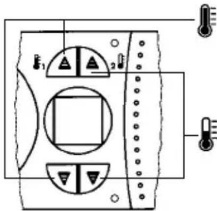
text_image
Technical diagram of an electronic device with labeled ports and indicators, including a thermometer and indicator lights.Temperatura comfort
p. es. +22°C
text_image
899.8℃ + +1 +2
text_image
1 2 000.0°C → +1 2text_image
Diagram of a dual-chamber electric motor with labeled terminals and control buttons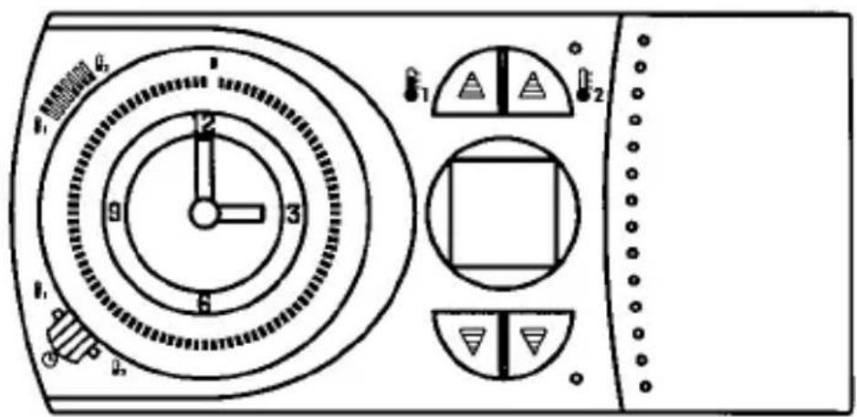
text_image
1 2 3 4 5 6 7 8 9 10 11 12 13 14 15 16 17 18 19 20 21 22 23 24 25 26 27 28 29 30 31 32 33 34 35 36 37 38 39 40 41 42 43 44 45 46 47 48 49 50 51 52 53 54 55 56 57 58 59 60 61 62 63 64 65 66 67 68 69 70 71 72 73 74 75 76 77 78 79 80text_image
Warning symbol image with exclamation mark inside triangle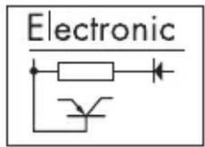
text_image
Electronic
text_image
AC ~natural_image
Technical line drawing of a mechanical device with directional arrows indicating motion (no text or symbols)text_image
Diagram showing electrical connections with screw and iron components, including a device panel and grounding symbols3.2 Conexión 5
natural_image
Simple electrical circuit diagram with three labeled terminals (③, ④, ⑤) and a switch symbol between terminals (no text or numerical labels)natural_image
Pure electrical circuit lines without any symbols

Indicación:
text_image
Technical diagram showing a device with a top panel and a bottom panel, both labeled with numerical indicators and an upward arrow.text_image
Diagram showing a clock with hour and minute hands, including a separate watch and a circular dial with time markings.text_image
Diagram showing a wristwatch and a circular dial with time markings and directional arrows indicating rotation or movement.
text_image
6°00 12 9 3 6 22°00
text_image
2400 600 2200 600 Sa Fr Do M.I 12 9 3 6 So Motext_image
Diagram of a temperature sensor or display panel with labeled components and indicators
text_image
Technical diagram of an electronic device with labeled ports and indicators, including a thermometer and indicator lights.Temperatura
confort
p.ej. +22°C
text_image
E1 888.0°C + +1 E2 E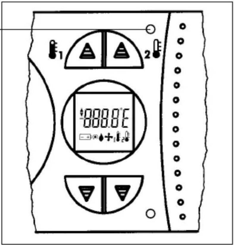
text_image
1 2 888.0°C +12text_image
Diagram of a dual-chamber electric motor with labeled terminals and control buttons
text_image
1 2 3 4 5 6 7 8 9 10 11 12 13 14 15 16 17 18 19 20 21 22 23 24 25 26 27 28 29 30 31 32 33 34 35 36 37 38 39 40 41 42 43 44 45 46 47 48 49 50 51 52 53 54 55 56 57 58 59 60 61 62 63 64 65 66 67 68 69 70 71 72 73 74 75 76 77 78 79 80natural_image
Technical line drawing of a mechanical device with directional arrows indicating rotation or movement (no text or symbols)text_image
Diagram showing electrical circuit components with screw and iron symbols, including a switch and power source3.1 Aansluiting
natural_image
Simple electrical circuit diagram with three labeled terminals (③, ④, ⑤) and a switch symbol between terminals (no text or numerical labels)natural_image
Pure electrical circuit lines without any symbols

Aanwijzing:
text_image
Technical diagram showing a device with a top panel and a bottom panel, both labeled with numerical indicators and an upward arrow.4. Tijd instellen

text_image
Diagram showing a clock with hour and minute hands, including a separate watch and a circular dial with time markings.Weekschakelklok
b. v. dinsdag 14.00 uur
1 segment = 15 minutes
text_image
Diagram of a temperature sensor or display panel with labeled components and indicators
text_image
Technical diagram of a device panel with labeled ports and indicators, including temperature sensors and control buttons.Gas- of olie gestookte 4,5 of 6
ketel voor grotere
wooneenheden
text_image
E1 888.0°C +1E2E
text_image
1 2 888.8°F → +12Subject to technical modifications. Status 8 / 97
natural_image
Simple gray oval shape with a central looped shape, no text or symbols present.
natural_image
Simple gray icon of a stylized letter 'O' with a small vertical bar beneath it (no text or symbols)
natural_image
Simple gray rectangular shape with a circular outline on the right (no text or symbols)