
HP 120 F - Range hood SCHOLTES - Free user manual and instructions
Find the device manual for free HP 120 F SCHOLTES in PDF.

| Product type | Decorative range hood |
| Brand | Scholtès |
| Model | HP 120 F |
| Width | 120 cm |
| Power supply | 230 V ~ 50 Hz |
| Number of speeds | 3 speeds + intensive speed |
| Lighting | Variable intensity (max, intermediate, off) |
| Grease filter | Washable (by hand or dishwasher), clean once a month |
| Activated carbon filter | Washable and reusable, replace every 3 years or if damaged |
| Saturation indicator | For grease filter (flashing LED) and carbon filter (manually activated) |
| Operating mode | External extraction or recirculation (with carbon filter) |
| Minimum distance to cooking surface | 65 cm (electric/ceramic) or 75 cm (gas) |
| Exterior material | Stainless steel (or other fireproof coating) |
| Noise level | Not specified, but suitable for domestic use |
| Exterior maintenance | Damp cloth with alcohol or non-abrasive products |
| Saturation indicator reset | Press and hold button 1 for 3 seconds after cleaning or replacing filter |
| Safety | Automatic shutdown after 5 min in intensive speed; do not flambé under the hood |
| Spare parts | Original parts available from authorized service centers |
| Compliance | European directives (Low Voltage, EMC, WEEE) |
| Weight | Not specified |
Frequently Asked Questions - HP 120 F SCHOLTES
User questions about HP 120 F SCHOLTES
0 question about this device. Answer the ones you know or ask your own.
Ask a new question about this device
Download the instructions for your Range hood in PDF format for free! Find your manual HP 120 F - SCHOLTES and take your electronic device back in hand. On this page are published all the documents necessary for the use of your device. HP 120 F by SCHOLTES.
USER MANUAL HP 120 F SCHOLTES
natural_image
Illustration of a hand holding a circular device with a screwdriver, showing internal components (no text or symbols)Fig. 4
natural_image
Diagram showing a rectangular object with an arrow inside, surrounded by hexagonal patterns (no text or symbols)natural_image
Exploded view diagram of a solar panel assembly showing internal components and mounting bracket (no text or labels)General information, 7
Data plate
Disposal
Precautions for operation,8
Information relating to installation
Using the hood, 9
Electric control panel
Lighting
Maintenance,10
Cleaning the outside of the appliance
Cleaning the grease filter
Replacing the carbon filter
Resetting the saturation indicator
Assembly, 32

GB
This instruction manual contains all the technical information necessary for the installation of the appliance.
The information and technical data provided is subject to change and the manufacturer, in line with technological progress, reserves the right to make any necessary modifications without prior notification.
All configurations and accessories linked to the appliance are described in the pages that follow, although some of these accessories may be optional and supplied on request.
In order to prolong the functional lifespan of the appliance and to guarantee maximum safety when using it, we recommend that the following instructions are followed carefully and that no electrical or mechanical variations are performed on the appliance or the exhaust ducting.
If you experience any problems, please contact the Authorised Technical Assistance Service and request original replacement parts.
Please read this manual carefully and follow all instructions provided so as to avoid damaging property or harming individuals.
WARNING: Before installing or using this hood, make sure that it has been approved in compliance with regulations EN60335-1 and EN60335-2-31. If no approval has been given (only specific local authorities are able to award this approval), DO NOT INSTALL THE HOOD OR ANY OF ITS COMPONENTS.
WARNING!
This document may only be used by the Installer or by Technical Assistance Service representatives; it should not be utilised by the end user of the product.
| DATA PLATE | |
| Electrical connections | voltage of 230V ~ 50Hz(see data plate) |
 | This appliance conforms to the following European Economic Community directives:-73/23/EEC dated 19/02/73 (Low Voltage) and subsequent amendments-89/336/EEC dated 03/05/89(Electromagnetic Compatibility) and subsequent amendments-93/68/EEC dated 22/07/93 and subsequent amendments.-90/336/EEC dated 29/06/90 (Gas) and subsequent amendments.-2002/96/EC |
Disposal of household appliances:
The European Directive 2002/96/EC relating to Waste Electrical and Electronic Equipment (WEEE) states that household appliances should not be disposed of using the normal solid urban waste cycle. Exhausted appliances should be collected separately in order to op timise the cost of re-using and recycling the materials inside the machine, while preventing potential damage to the atmosphere and to public health. The crossed-out dustbin is marked on all products to remind the owner of their obligations regarding separated waste collection.
For further information relating to the correct disposal of exhausted household appliances, owners may contact the public service provided or their local dealer.
The hood is supplied for operation as a ducted (“air extraction”) version or a filter (“air recirculation”) version (see following page); if installed as a filter hood, check whether it has already been fitted with a carbon filter and if it has not, order one from an authorised technical assistance centre.
It is therefore important to make sure that the kitchen has adequate ventilation so that the appliance can operate efficiently.
The appliance must not be connected to ducting used for the discharge of fumes produced by other appliances which are powered with any energy sources besides electricity.
If the hood must be installed in a kitchen where there is a water heater or gas heating system, it is strongly recommended, for safety reasons, that the ducted version is NOT installed.
In this case, the appliance must be fitted with an active carbon filter, which may be purchased from your local dealer. This will enable the appliance to be used as an air recirculation model.
The lowest part of the hood must be positioned at least 65 cm above the hob (for glass ceramic or traditional electric hobs), or 75 cm if a gas hob is installed.
If the installation instructions for the gas cooker specify a greater distance, take this measurement into consideration when installing the hood. Warning! Where hoods with non-stainless steel exteriors are installed (including painted finishes, adhesive films or applications of any type), make sure that the finish consists of a fireproof material and only use the product after authorisation is given following a detailed and precise risk assessment procedure, performed by a qualified technician who is endorsed by the relevant local authorities.
If the hood is used at the same time as a burner or fire which is dependent on the air in the room during the combustion process (such as gas-, fuel oil-, coal- or wood-fired heating systems, water heaters, etc.) exercise extreme caution as the hood removes air from the room.
For safe operation, the underpressure must not exceed 0.04 mbar; this will prevent exhaust fumes from being drawn back into the room.
This can be achieved by ensuring air inlets which cannot become blocked are provided, for example outside wall air circulation vents, doors, windows or other technical devices.
Flambée cooking damages filters and can cause fires; avoid cooking in this manner at all costs.
This hood is intended for domestic use only.
This hood may only be used for the extraction of fumes and smoke produced while cooking foods.
For all problems relating to the discharge of smoke, please refer to the legislation set out by the relevant local authority.
We shall not be held responsible for any damage or fires resulting from the non-observance of the above instructions when using this appliance.
Information relating to installation
The hood can operate in the following ways:
Ducted ("air extraction") version:
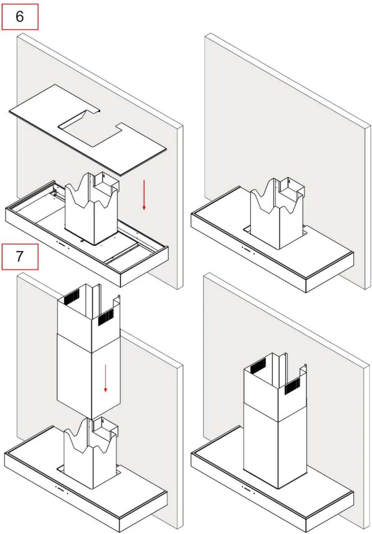
Smoke and steam are drawn in, then directed through a suitable duct (sold separately) until they are expelled outside or into a purpose-built shared exhaust duct.
If fitted, remove the carbon filter.
The airflow deviator must not be installed.
Filter ("air recirculation") version:
Smoke and steam are drawn in and purified using an active carbon filter, then redirected back into the kitchen with the help of the airflow deviator.
Make sure that the hood is already fitted with a carbon filter; if necessary, order one and install it.
You will also need a short piece of ducting (sold separately) to connect the motor assembly outlet to the flow deviator.
GB
- The hood has several operating speeds.
For more efficient performance, use the lowest suction level when there is only a small amount of smoke or steam and the higher suction level when there are large amounts of smoke and steam; there is also an intermediate suction level, which should be used when the amount of smoke and steam produced by the cooking process is at a normal level. - We recommend that the hood is switched on a few minutes before the cooking process is started, and that it is only switched off after all the odours have been completely eliminated.
Please note: The product can be supplied with a remote control on request.
Electric control panel:
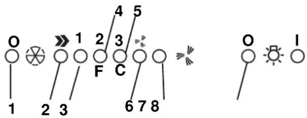
- Motor ON/OFF button
- ON button; also used to select the motor speed 1 - 2 - 3 - 1 - 2
- Speed 1 indicator LED
- Speed 2 indicator LED; also indicates when the grease filter is saturated (in which case the LED flashes - see instructions relating to cleaning the grease filter).
- Speed 3 indicator LED; also indicates when the active carbon filter is saturated (in which case the LED flashes - see instructions relating to replacing the active carbon filter).
Warning! The device signalling the active carbon filter saturation is deactivated.
If you wish to install an active carbon filter, activate the device signalling the active carbon filter saturation by pressing the buttons 2 and 7 simultaneously and holding them down for 3 seconds. At the start of this process, only LED 4 will be flashing; after 3 seconds LED 5 will also begin to flash, to indicate that the active carbon filter saturation detection device is now active.
To deactivate it, press the two buttons again: after 3 seconds LED 5 will stop flashing and the device will be deactivated.
-
Intensive speed indicator LED
-
Intensive speed activation button.
-
Intensive speed indicator LED
- Intensive speed activation button.
We recommend that this speed is used when there is a particularly high concentration of smoke and odours (for example, when cooking fish or frying food).
Once activated, the intensive speed function operates for approximately 5 minutes, after which the previously selected operating speed (between 1 and 3) is restored or the appliance even switches off if no speed at all was selected previously. To deactivate the intensive speed function before 5 minutes have elapsed, press button 1 or button 2.
- Lights ON/OFF button
The level of illumination can be adjusted using button 8. If the button is pressed once the lights are switched on at the maximum level. When the button is pressed a second time, the illumination level is reduced to medium. When pressed a third time, the lights switch off.
If any problems relating to the operation of the appliance arise, before contacting the technical assistance service, unplug the product to disconnect it from the electricity supply for at least 5 seconds, then reconnect it. If the problem persists, make sure that the control panel is connected to the main control unit inside the hood correctly. If the problem has still not been resolved, contact the technical assistance service.
Lighting
Disconnect the appliance from the electricity supply.
a. Remove the cover of the recessed lamp by using a small screwdriver to lever it out (Fig. 4).
b. Replace the faulty lightbulb with an identical one.
c. Replace the lamp cover.
d. If the lighting system does not work, make sure the lamps have been inserted correctly before contacting the technical assistance service.

natural_image
Illustration of a hand holding a circular device with a screwdriver, showing internal components (no text or symbols)Fig. 4
Disconnect the appliance from the electricity supply before performing any type of maintenance work on it.
To ensure the hood operates efficiently and consistently, we recommend that maintenance is performed regularly (every ten days on average).
Cleaning the outside of the appliance
Clean the external surfaces of the appliance regularly.
To clean the hood thoroughly, use a cloth which has been dampened with alcohol or any of the special cleaning products currently available in shops.
Do not use products which contain abrasive substances.
Cleaning the grease filter
The grease filter is used to trap suspended particles of grease which are produced during the cooking process.
It should be cleaned once a month using non-aggressive detergent, either manually or in the dishwasher, at a low temperature using a short cycle.
If cleaned in the dishwasher the filter may become opaque over time, but its filtering capacity will not be diminished in any way.

natural_image
Diagram showing a rectangular object inside a container with circular patterns and an arrow indicating rotation (no text or symbols)Fig. 5
Remove it using the handle attached, pushing it backwards then pulling it downwards (Fig. 5).
After washing it, dry it carefully and replace it, following the above instructions in reverse order.
Replacing the carbon filter
The carbon filter is used to remove grease and odours from the air before it is released back into the room through the upper grille.
The carbon filter may be washed every two months, using hot water and suitable detergent or a dishwasher cycle at 65^ C (if cleaned in the dishwasher, run an entire cycle when no crockery is inside).
Remove excess water without damaging the filter, then remove the matting inside the plastic frame and place the filter in the oven at 100^ C for 10 minutes to dry it thoroughly.
Replace the active carbon filter every three years or if it is damaged
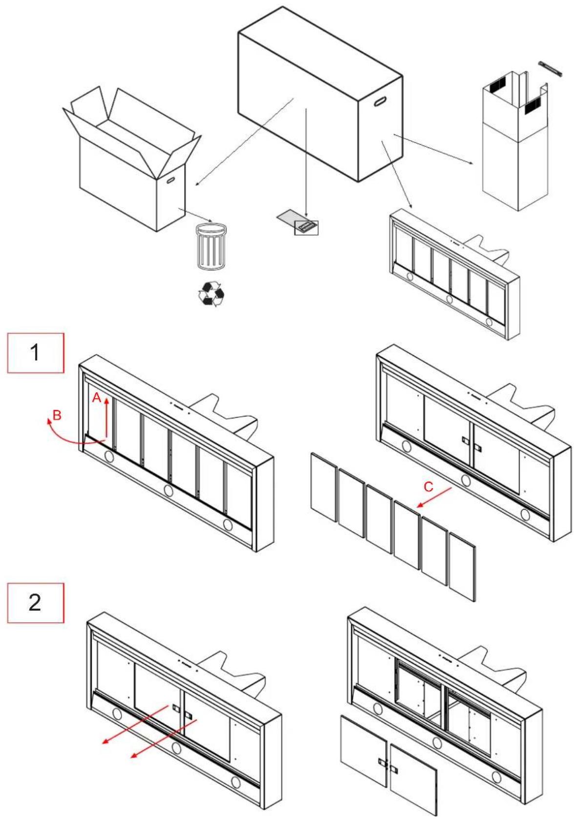
To fit or replace the carbon filter:
Remove the grease filter(s).
Fit the frame holding the carbon filter in place and fix it to the motor assembly using 4 screws.
Position the carbon filter matting over the frame and fix it in place using the bracket provided.
Fit the grease filter(s).

natural_image
Exploded view diagram of a solar panel assembly showing internal components and mounting features (no text or labels)Resetting the saturation indicator
After cleaning or replacing the filter, press and hold button 1 for 3 seconds, until LED 4 or 5 stops flashing. Please see page 4.
Warning! The filter saturation indicator MUST be reset when the hood is in Standby, therefore the hood should not be disconnected from the electricity supply.
Warning:
The manufacturer will not be held responsible for any motor damage or fires where the maintenance of the filters has not been performed as described in this manual.
FR


Italiano, 1 Français, 11 English, 6

Deutsch, 16 Nederlands, 21 Español, 27
HP 90 I
HP 120 F
Sommaire
Généralités, 14
natural_image
Illustration of a hand holding a circular device with a handle, showing internal components and a magnified view (no text or symbols)Fig. 4
FR
natural_image
Diagram showing a rectangular object inside a container with circular patterns and an arrow indicating rotation (no text or symbols)natural_image
Exploded view diagram of a modular device showing internal components and assembly (no text or labels)natural_image
Illustration of a hand holding a small circular object with a screwdriver, alongside an open ring (no text or symbols)Fig. 4
natural_image
Diagram showing a rectangular object inside a container with circular patterns and an arrow indicating rotation (no text or symbols)natural_image
Exploded view diagram of a solar panel assembly showing internal components and mounting bracket (no text or labels)natural_image
Illustration of a hand holding a circular device with a screwdriver, showing internal components (no text or symbols)Fig. 4
natural_image
Diagram showing a rectangular object with an arrow inside, surrounded by circular patterns (no text or symbols)natural_image
Exploded view diagram of a solar panel assembly showing internal components and mounting bracket (no text or labels)natural_image
Illustration of a hand holding a circular device with a screwdriver, showing internal components (no text or symbols)Fig. 4
natural_image
Diagram showing a rectangular object inside a container with circular patterns and an arrow indicating rotation (no text or symbols)natural_image
Exploded view diagram of a solar panel assembly showing internal components and mounting bracket (no text or labels)natural_image
Isometric line drawing of a two-tiered storage unit with a base platform (no text or symbols)ES
ES
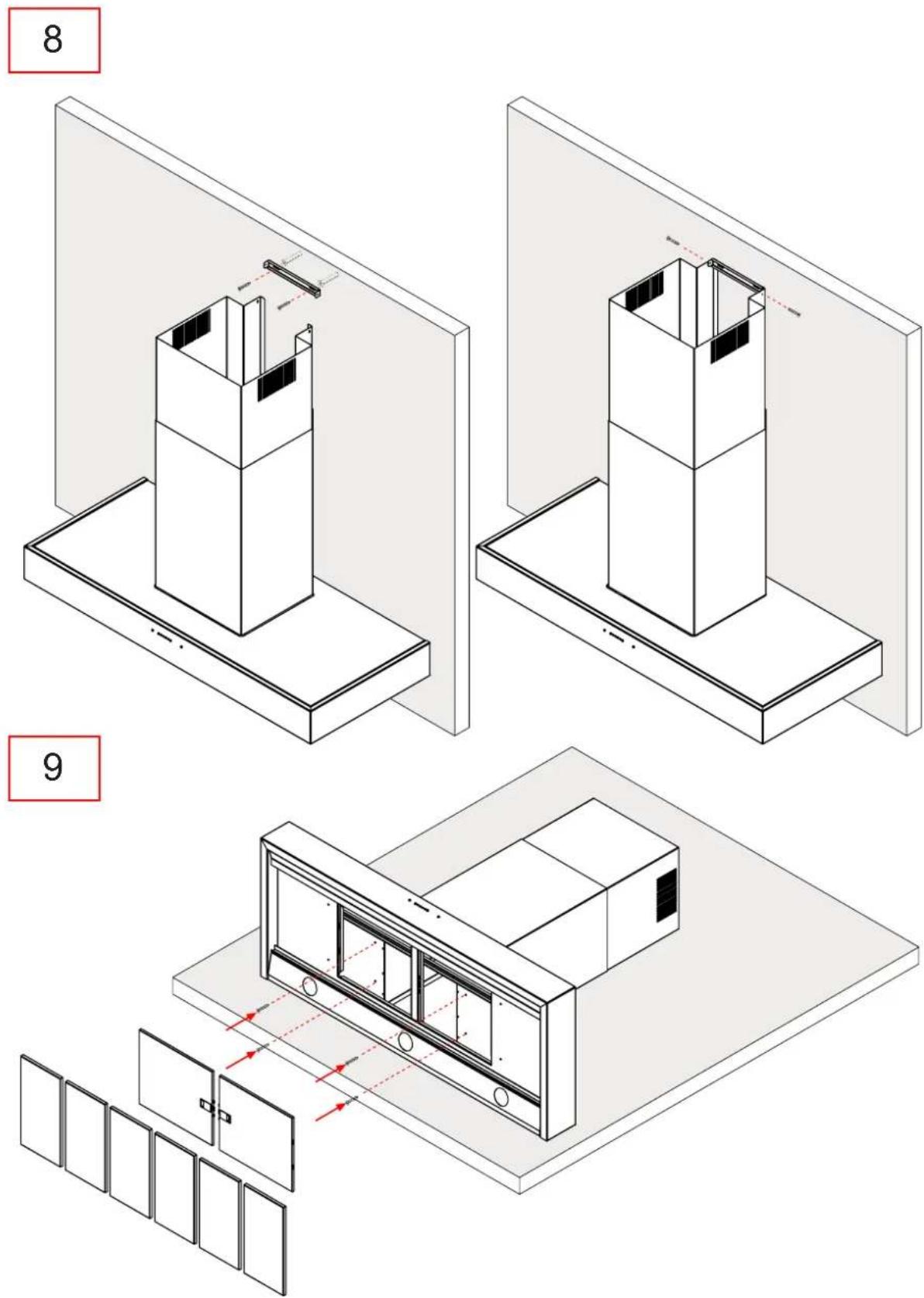
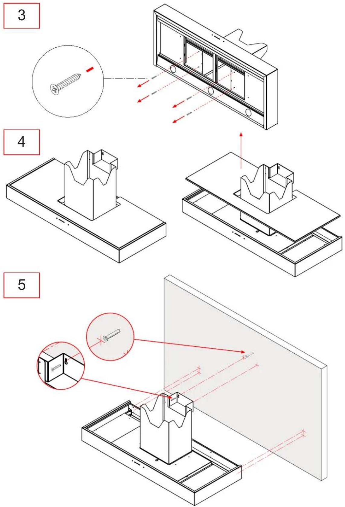
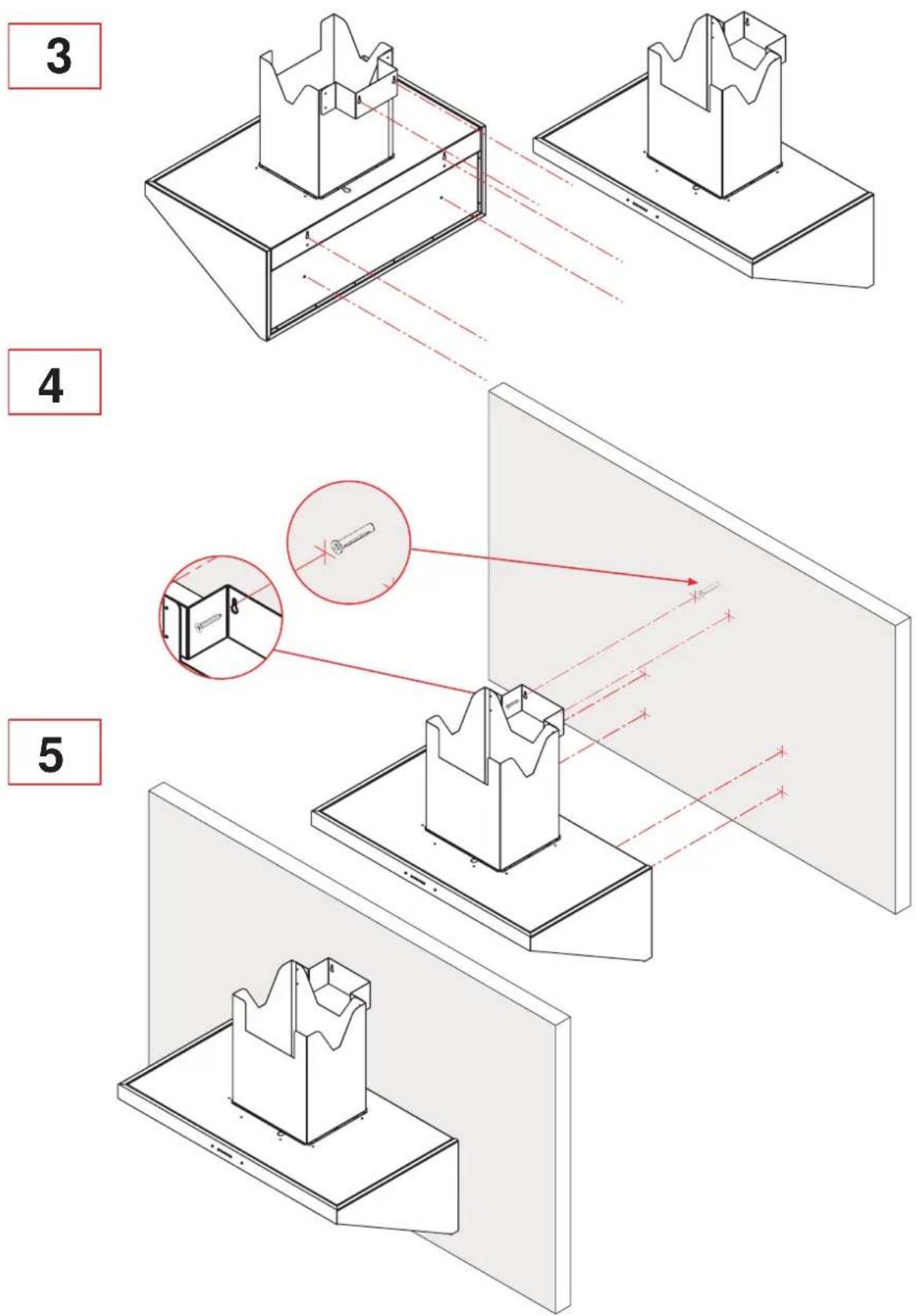
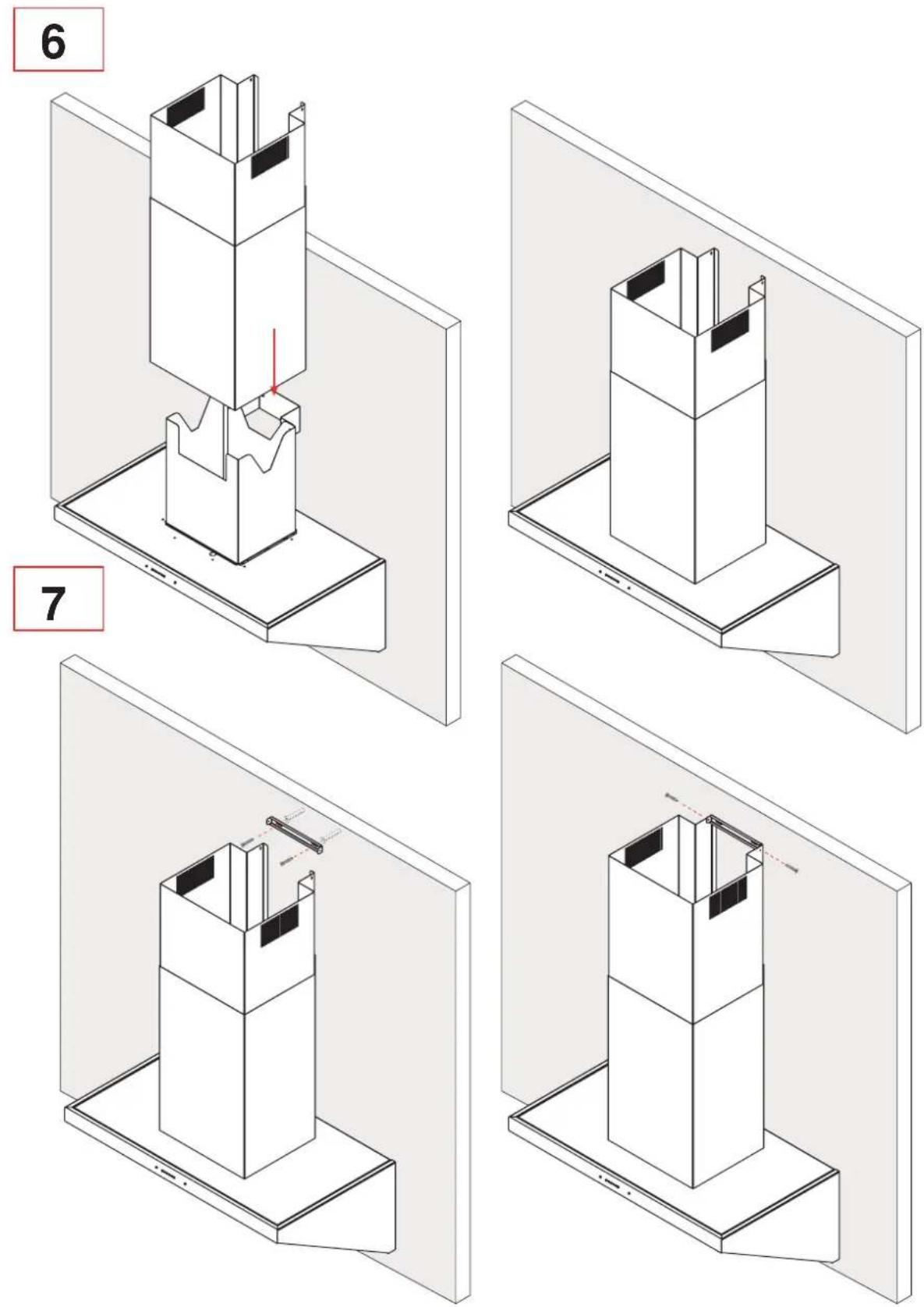
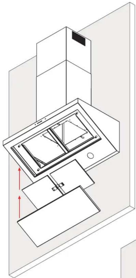
Assembly instructions
Mode d'assemblage
Bauanleitung
natural_image
Line drawing of a kitchen appliance with a mounted panel and a cabinet (no text or symbols)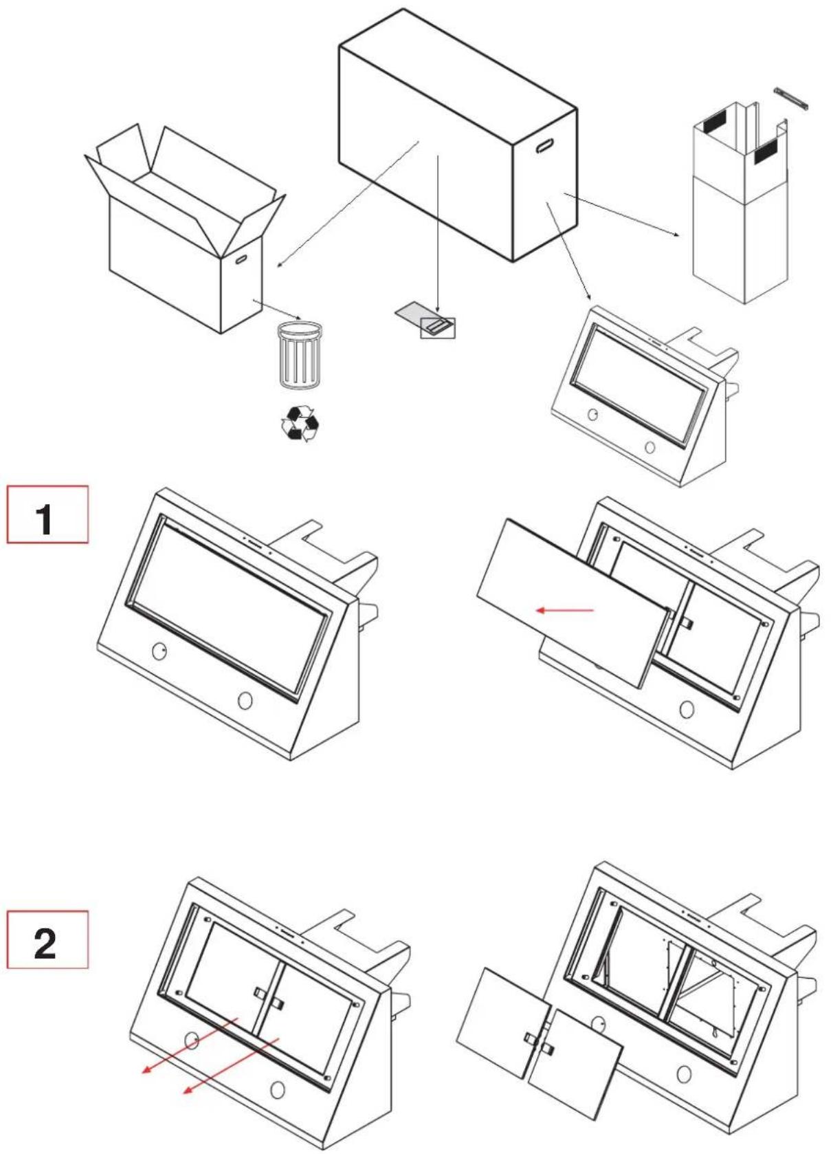
ES
ES
8
natural_image
Isometric line drawing of a laptop with internal components and a red directional arrow indicating motion (no text or symbols)9

natural_image
Isometric line drawing of a kitchen appliance mounted on a wall, showing a tray and cabinet (no text or symbols)ES
ES
ES
- GB
- WARNING!
- Disposal of household appliances:
- Information relating to installation
- Ducted ("air extraction") version:
- Filter ("air recirculation") version:
- Lighting
- Cleaning the outside of the appliance
- Cleaning the grease filter
- Replacing the carbon filter
- Resetting the saturation indicator
- Warning:
- Sommaire
- FR
Brand : SCHOLTES
Model : HP 120 F
Category : Range hood