
HSG 98 - Range hood SCHOLTES - Free user manual and instructions
Find the device manual for free HSG 98 SCHOLTES in PDF.

| Brand | Scholtès |
| Model | HSG 98 |
| Product Type | Cooker Hood |
| Height | 104 - 124 cm |
| Width | 80 cm |
| Depth | 35 cm |
| Gross Weight | 33.7 kg |
| Power Supply | 220-240 V (see rating plate) |
| Total Power Consumption | 315 W |
| Motor Power Consumption | 1 x 250 W |
| Exhaust Duct Diameter | 150 mm |
| Exhaust Type | Extracting or recirculating (optional kit) |
| Number of Speeds | 4 speeds + timed intensive |
| Lighting | 1 halogen bulb 12 V 20 W Ø35 GU4 + 1 neon T5 13 W 517 mm |
| Grease Filter | Metallic, dishwasher-safe (clean once a month) |
| Charcoal Filter | Washable every 2 months, pad to be replaced every 3 years |
| Filter Saturation Indicator | Yes (reset button, red flashing for grease, red steady for charcoal) |
| Minimum Safety Distance | 50 cm (electric) / 65 cm (gas or mixed) |
| Maintenance | Clean exterior with a damp cloth and neutral detergent; do not use alcohol |
| Included Accessories | Fixing plugs |
| Repairability | Contact authorized technical support service |
| Warranty | See general terms and conditions |
Frequently Asked Questions - HSG 98 SCHOLTES
User questions about HSG 98 SCHOLTES
0 question about this device. Answer the ones you know or ask your own.
Ask a new question about this device
Download the instructions for your Range hood in PDF format for free! Find your manual HSG 98 - SCHOLTES and take your electronic device back in hand. On this page are published all the documents necessary for the use of your device. HSG 98 by SCHOLTES.
USER MANUAL HSG 98 SCHOLTES


natural_image
Illustration of a computer motherboard with a hand inserting a cable into a box, showing internal components and airflow indicators (no text or symbols)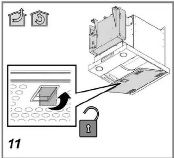

natural_image
Technical line drawing of a mechanical device with a black arrow indicating a component, labeled '17' at bottom (no text or symbols on the diagram itself)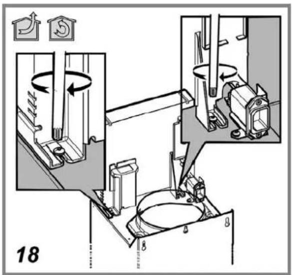


natural_image
Technical illustration of a refrigerated industrial machine with internal components and airflow indicators (no text or symbols)


natural_image
Diagram showing a rectangular object with dashed lines and an arrow, placed on a patterned surface (no text or symbols)The hood can look different to that illustrated in the drawings in this booklet. The instructions for use, maintenance and installation, however, remain the same.
! It is important to conserve this booklet for consultation at any moment. In the case of sale, cession or move, make sure it is together with the product.
! Read the instructions carefully: there is important information about installation, use and safety.
! Do not carry out electrical or mechanical variations on the product or on the discharge conduits.
GENERAL SAFETY
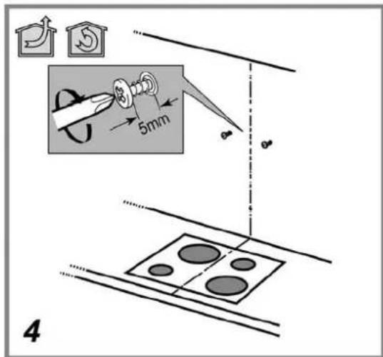
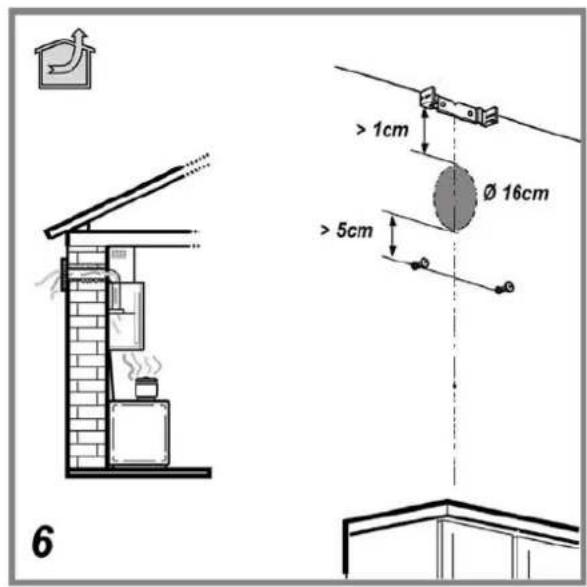
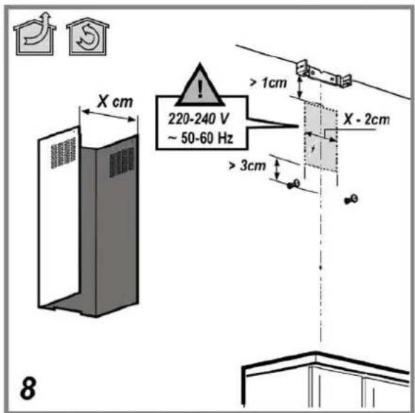
The minimum distance between the supporting surface for the cooking equipment on the hob and the lowest part of the range hood must be not less than 50cm from electric cookers and 65cm from gas or mixed cookers.
If the instructions for installation for the gas hob specify a greater distance, this must be adhered to.
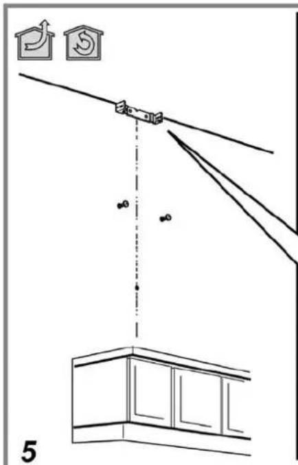
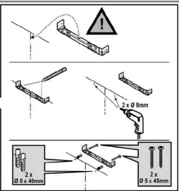
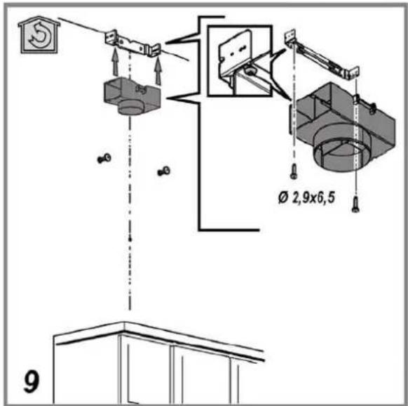
Expansion wall plugs are provided to secure the hood to most types of walls/ceilings. However, a qualified technician must verify suitability of the materials in accordance with the type of wall/ceiling. The wall/ceiling must be strong enough to take the weight of the hood. Do not tile, grout or silicone this appliance to the wall. Surface mounting only.
WARNING! Do not connect the appliance to the mains until the installation is fully complete.
Before any cleaning or maintenance operation, disconnect hood from the mains by removing the plug or disconnecting the mains electrical supply.
Always wear work gloves for all installation and maintenance operations.
The appliance is not intended for use by children or persons with impaired physical, sensorial or mental faculties, or if lacking in experience or knowledge, unless they are under supervision or have been trained in the use of the appliance by a person responsible for their safety.
This appliance is designed to be operated by adults, children should be monitored to ensure that they do not play with the appliance.
This appliance is designed to be operated by adults. Children should not be allowed to tamper with the controls or play with the appliance.
Never use the hood without effectively mounted grating!
The hood must NEVER be used as a support surface unless specifically indicated.
The premises where the appliance is installed must be sufficiently ventilated, when the kitchen hood is used together with other gas combustion devices or other fuels.
The ducting system for this appliance must not be connected to any existing ventilation system which is being used for any other purpose such as discharging exhaust fumes from appliances burning gas or other fuels.
The flaming of foods beneath the hood itself is severely prohibited.
The use of exposed flames is detrimental to the filters and may cause a fire risk, and must therefore be avoided in all circumstances.
Any frying must be done with care in order to make sure that the oil does not overheat and ignite.
With regards to the technical and safety measures to be adopted for fume discharging it is important to closely follow the regulations provided by the authorised authorities.
The hood must be regularly cleaned on both the inside and outside (AT LEAST ONCE A MONTH).
This must be completed in accordance with the maintenance instructions provided in this manual). Failure to follow the instructions provided in this user guide regarding the cleaning of the hood and filters will lead to the risk of fires.
Do not use or leave the hood without the lamp correctly mounted due to the possible risk of electric shocks.
We will not accept any responsibility for any faults, damage or fires caused to the appliance as a result of the non-observance of the instructions included in this manual.
ELECTRICAL CONNECTION
The mains power supply must correspond to the rating indicated on the plate situated inside the hood. If provided with a plug connect the hood to a socket in compliance with current regulations and positioned in an accessible area. If it not fitted with a plug (direct mains connection) or if the plug is not located in an accessible area apply a double pole switch in accordance with standards which assures the complete disconnection of the mains under conditions relating to over-current category III, in accordance with installation instructions.
Warning! Before re-connecting the hood circuit to the mains supply and
checking the efficient function, always check that the mains cable is correctly assembled.
Replacing the power cable
Warning! Power cable replacement must be undertaken by the authorised service assistance centre or similar qualified person.
AIR VENT
(for the suction versions)
Connect the hood and discharge holes on the walls with a diameter equivalent to the air outlet (connection flange).
Using the tubes and discharge holes on walls with smaller dimensions will cause a diminution of the suction performance and a drastic increase in noise.
Any responsibility in the matter is therefore declined.
! Use a duct of the minimum indispensable length.
! Use a duct with as few elbows as possible (maximum elbow angle: 90°).
! Avoid drastic changes in the duct cross-section.
! Use a duct with an as smooth as possible inside.
! The duct must be made of certified material.
! The company declines any responsibility whenever these regulations are not respected.
FILTERING OR DUCTING ?
! Your cooker hood is ready to be used in suction version.
To use the hood in filtering version the special ACCESSORY KIT must be installed.
Check on the first pages of this manual if the ACCESSORY KIT is furnished or must be bought separately.
Note: If furnished, in certain cases, the additional activated carbon filtering system may be installed on the hood.
Information about the conversion of the hood from suction version to filtering version is present in this manual.

Ducting version
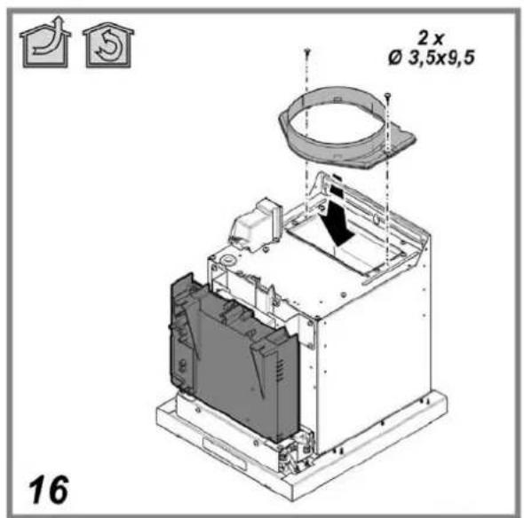
In this case the fumes are conveyed outside by means of a special pipe connected with the connection ring located on top of the hood.
Attention! The exhausting pipe is not supplied and must be purchased apart.
Diameter of the exhausting pipe must be equal to that of the connection ring = 150mm.
In the horizontal runs the exhausting pipe must be slightly slanted (about 10^ ) and directed upwards to vent the air easily from the room to the outside.
Attention! If the hood is supplied with active charcoal filter, then it must be removed.

Filter version
One active charcoal filter is needed for this and can be obtained from your usual retailer.
The filter removes the grease and smells from the extracted air before sending it back into the room through the upper outlet grid.
CONTROLS
EN

- Reset Button for saturation of filters: the hood will warn the user that it is time to do maintenance work on the filters, by giving out a light-signal. Red-light Button blinking: carry out the maintenance of the greasy filters, following this press the button for over 3 seconds and the button will turn off.
Red-light Button: carry out maintenance on carbon-filters, following this press the button for more than 3 seconds, the button will switch off.
Attention: the hood is provided only with a warning signal for greasy filters.
To put into function the greasy-filter signal:: Set the cooker-hood off, press switch button no.6 for more than 3 seconds (the switch will turn on red signalling that the function has been set.
To disactivate the carbon filter signal, repeat the entire procedure again.

- Speed selecting button (speed rating) for intensive suction (with timer): press to select the suction-speed (rating), the functioning-time is 5 minutes (blinking push-button), following this the suction function will either turn off or return to the suction-speed that had previously been selected.
Note: It is possible to keep a check of this function so that the hood switches off 5 minutes after it has worked, (even though another function had been selected prior to this one) after having pressed the button, press again and keep pressed, the pilot-light will start blinking indicating that the selected function has been set..
- Speed selecting button suction speed 3: press this switch once to select the speed rating of suction speed, press again and keep pressed to activate the time-function for 10 minutes (blinking light) following this the cooker-hood will switch off..

- Speed selecting button suction speed 2: press this switch once to select the speed rating of suction speed, press again and keep pressed to activate the time-function for 15 minutes (blinking light) following this the cooker-hood will switch off.
- Switch OFF suction / ON speed (rating) of suction speed 1: press this switch once turn off the speed (rating) of suction function that has been selected or (if no speed rating of suction function select the speed (rating) of suction speed 1, press again and keep pressed to activate the time-function for 20 minutes (blinking light), following this the cooker hood will switch off.

- Switch ON/OFF Pilot-lights: press to switch on/off lights.
EN
MAINTENANCE
ATTENTION! Before performing any maintenance operation, isolate the hood from the electrical supply by switching off at the connector and removing the connector fuse.
Or if the appliance has been connected through a plug and socket, then the plug must be removed from the socket.
Cleaning
The cooker hood should be cleaned regularly (at least with the same frequency with which you carry out maintenance of the fat filters) internally and externally. Clean using the cloth dampened with neutral liquid detergent. Do not use abrasive products. DO NOT USE ALCOHOL!
WARNING: Failure to carry out the basic cleaning recommendations of the cooker hood and replacement of the filters may cause fire risks.
Therefore, we recommend oserving these instructions.
The manufacturer declines all responsibility for any damage to the motor or any fire damage linked to inappropriate maintenance or failure to observe the above safety recommendations.
Maintenance of the anti-grease filters
Traps cooking grease particles.
This must be cleaned once a month using non aggressive detergents, either by hand or in the dishwasher, which must be set to a low temperature and a short cycle. When washed in a dishwasher, the grease filter may discolour slightly, but this does not affect its filtering capacity.
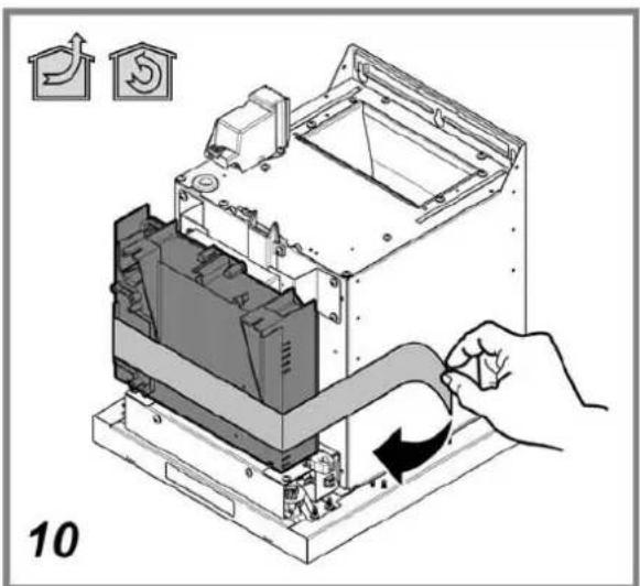
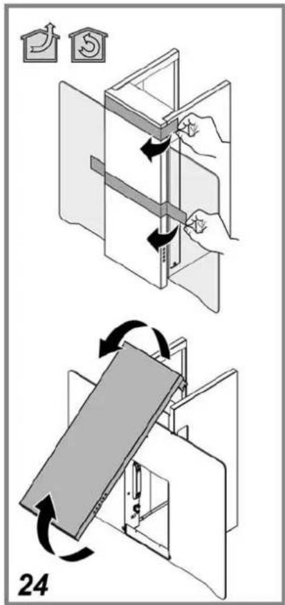
To remove the grease filter, pull the spring release handle.

natural_image
Diagram showing a rectangular object partially submerged in a liquid with circular patterns, no text or symbols present.Maintenance of the charcoal filter
It absorbs unpleasant odours caused by cooking.
The charcoal filter can be washed once every two months using hot water and a suitable detergent, or in a dishwasher at 65^ C (if the dishwasher is used, select the full cycle function and leave dishes out).
Eliminate excess water without damaging the filter, then remove the mattress located inside the plastic frame and put it in the oven for 10 minutes at 100^ C to dry completely. Replace the mattress every 3 years and when the cloth is damaged.
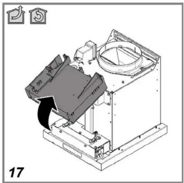
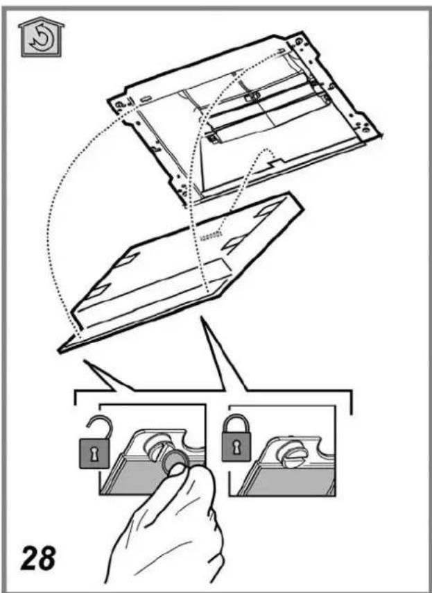
Remove the filter holder frame by turning the knobs (g) 90° that affix the chimney to the cooker hood.
Insert the pad (i) of activated carbon into the frame (h) and fit the whole back into its housing (j).

Replacing lamps
Disconnect the hood from the electricity.
Warning! Prior to touching the light bulbs ensure they are cooled down.
- Use a small screwdriver as a lever on the borders of the lamp in order to remove the lightbulb.
- Slide out the lightbulb to be replaced and replace with a new 12V 20W MAX 30° Ø35 12V GU4.
- Carry out the replacement and mount the new lightbulb by following instructions in the reverse.

Replacing lateral lamps.
Remove the ceiling light unscrewing the locking screw.
Replace the damaged lamp with one having the same technical characteristics.
Use neon lamps T5 13W 517 mm (G5).

EN
DISPOSAL
This appliance is marked according to the European directive 2002/96/EC on Waste Electrical and Electronic Equipment (WEEE). By ensuring this product is disposed of correctly, you will help prevent potential negative consequences for the environment and human health, which could otherwise be caused by inappropriate waste handling of this product.

The symbol ■ on the product, or on the documents accompanying the product, indicates that this appliance may not be treated as household waste. Instead it should be taken to the appropriate collection point for the recycling of electrical and electronic equipment. Disposal must be carried out in accordance with local environmental regulations for waste disposal.
MALFUNCTIONS
If something appears not to be working properly, do the following simple checks before calling Technical Service:
• If the hood is not working:
Check that:
- The power has not been disconnected.
- A speed has been selected.
- If the hood performs inefficiently:
Check that:
- The motor speed selected is sufficient for the amount of smoke and vapours released.
- The kitchen is sufficiently ventilated to allow air intake.
- The charcoal filter is not worn (hood in filtering version).
- If the hood has turned off during normal functioning:
Check that:
- The power has not been disconnected.
- the omnipolar disconnection device has not tripped.
If the hood fails to operate correctly, briefly disconnect it from the mains power supply for almost 5 sec. by pulling out the plug. Then plug it in again and try once more before contacting the Technical Assistance Service.
TECHNICAL DATA
Model HSG 98
Height 104 ÷ 124 cm
Width 80 cm
Depth 35 cm
Gross weight: 33,7 Kg
Total absorption 315 W
Motor absorption 1x250 W
Lamp absorption 2x20 W (G4 12V)
Lamp absorption 2x13 W (T5 - G5)
Exhaust pipe ∅ 15 cm
This appliance conforms to the following EEC Directive:
- "Low Voltage Equipment" Directive 2006/95/EC (12-12-2006)
• "Electromagnetic Compatibility" Directive 2004/108/EC (15-12-2004)

Components not provided with the product
natural_image
Diagram showing a rectangular object partially submerged in a liquid with circular patterns below (no text or symbols)Absorption ampoule 2x20 W (G4 12V)
Absorption ampoule 2x13 W (T5 - G5)
natural_image
Diagram showing a 3D rectangular block placed on a textured surface with circular patterns, no text or symbols present.Vervanging lampjes
Sluit de stroom af.
natural_image
Diagram showing a rectangular object partially submerged in a liquid with circular patterns below (no text or symbols)• "Low voltage" Directive 2006/95/EC (12-12-2006)
• "EMC" Directive 2004/108/EC (15-12-2004)

natural_image
Diagram showing a rectangular structure with a curved arrow, surrounded by circular patterns (no text or symbols)- GENERAL SAFETY
- ELECTRICAL CONNECTION
- Replacing the power cable
- AIR VENT
- FILTERING OR DUCTING ?
- Ducting version
- Filter version
- CONTROLS
- EN
- MAINTENANCE
- Cleaning
- Maintenance of the anti-grease filters
- Traps cooking grease particles.
- Maintenance of the charcoal filter
- It absorbs unpleasant odours caused by cooking.
- Replacing lamps
- DISPOSAL
- MALFUNCTIONS
- TECHNICAL DATA
- Vervanging lampjes
Brand : SCHOLTES
Model : HSG 98
Category : Range hood