
HSB 99 - Range hood SCHOLTES - Free user manual and instructions
Find the device manual for free HSB 99 SCHOLTES in PDF.

| Product type | Hood |
| Brand | Scholtès |
| Model | HSB 99 |
| Height | 72-114 cm |
| Width | 89.8 cm |
| Depth | 45 cm |
| Gross weight | 25.2 kg (HSB 99 IX) / 28 kg (HSB 99 CL) |
| Total absorption | 215 W |
| Motor absorption | 1 x 175 W |
| Exhaust pipe diameter | 15 cm |
| Controls | Touch, 3 speeds + intensive, timer, lighting |
| Lighting | Halogen bulbs 12V - 20W max - G4 |
| Filters | Metal grease filter (washable) + activated charcoal filter (optional, to be replaced every 4 months) |
| Minimum safety distance | 50 cm (electric) / 65 cm (gas or mixed) |
| Version | Suction as standard, convertible to recirculation with optional kit |
| Special functions | Timer, filter saturation signal, intensive speed 5 min |
| Maintenance | Monthly cleaning of grease filters, replace charcoal filter every 4 months |
Frequently Asked Questions - HSB 99 SCHOLTES
User questions about HSB 99 SCHOLTES
0 question about this device. Answer the ones you know or ask your own.
Ask a new question about this device
Download the instructions for your Range hood in PDF format for free! Find your manual HSB 99 - SCHOLTES and take your electronic device back in hand. On this page are published all the documents necessary for the use of your device. HSB 99 by SCHOLTES.
USER MANUAL HSB 99 SCHOLTES
natural_image
Abstract black-and-white circular pattern with petal-like shapes radiating outward (no text or symbols)Scholtès


flowchart
graph TD
    A["Component 1"] --> B["Arrow to Column 1"]
    B --> C["Arrow to Column 2"]
    C --> D["Arrow to Column 3"]
    D --> E["Arrow to Column 4"]
    E --> F["Arrow to Column 5"]
flowchart
graph TD
    A["Top Left Component"] --> B["Top Right Component"]
    B --> C{Flow Direction}
    C -->|Yes| D["Downward Arrow"]
    C -->|No| E["Upward Arrow"]
    D --> F["Bottom Right Component"]
    E --> F
    F --> G["Bottom Left Component"]
    style A fill:#f9f,stroke:#333
    style B fill:#f9f,stroke:#333
    style C fill:#ccf,stroke:#333
    style D fill:#cfc,stroke:#333
    style E fill:#fcc,stroke:#333
    style F fill:#cff,stroke:#333
    style G fill:#ffc,stroke:#333


flowchart
graph TD
    A["Component 5"] --> B["Directional Arrow"]
    B --> C["Main Component"]
    C --> D["Output"]
    style A fill:#f9f,stroke:#333
    style B fill:#ccf,stroke:#333
    style C fill:#cfc,stroke:#333
    style D fill:#fcc,stroke:#333

natural_image
Technical diagram of a mechanical device with a cylindrical spring and labeled part 23 (no text or symbols on the diagram itself)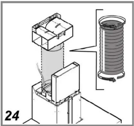
natural_image
Technical diagram of a mechanical assembly with labeled components (no readable text or symbols)

natural_image
Diagram showing a downward arrow and a rectangular object on a horizontal line, no text or symbols presentErsetzen der Lampen
natural_image
Illustration of a hand holding a magnifying glass with a small blue object, alongside another hand holding a circular component (no text or symbols present)ENTSORGUNG
The hood can look different to that illustrated in the drawings in this booklet. The instructions for use, maintenance and installation, however, remain the same.
! It is important to conserve this booklet for consultation at any moment. In the case of sale, cession or move, make sure it is together with the product.
! Read the instructions carefully: there is important information about installation, use and safety.
! Do not carry out electrical or mechanical variations on the product or on the discharge conduits.
GENERAL SAFETY
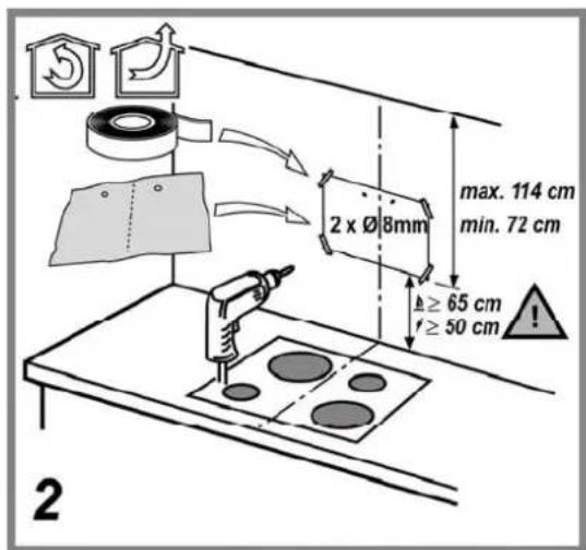
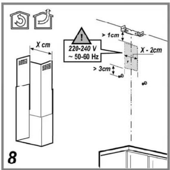
The minimum distance between the supporting surface for the cooking equipment on the hob and the lowest part of the range hood must be not less than 50cm from electric cookers and 65cm from gas or mixed cookers.
If the instructions for installation for the gas hob specify a greater distance, this must be adhered to.
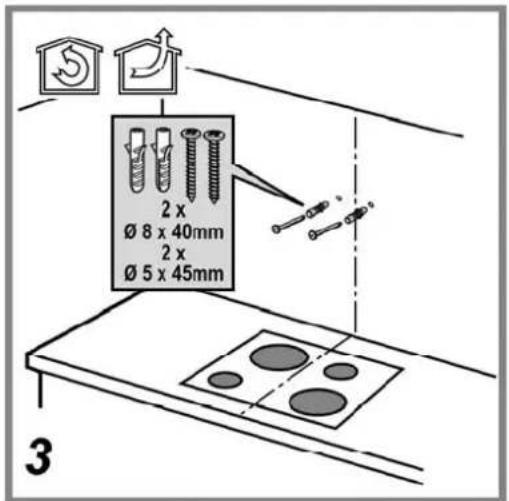
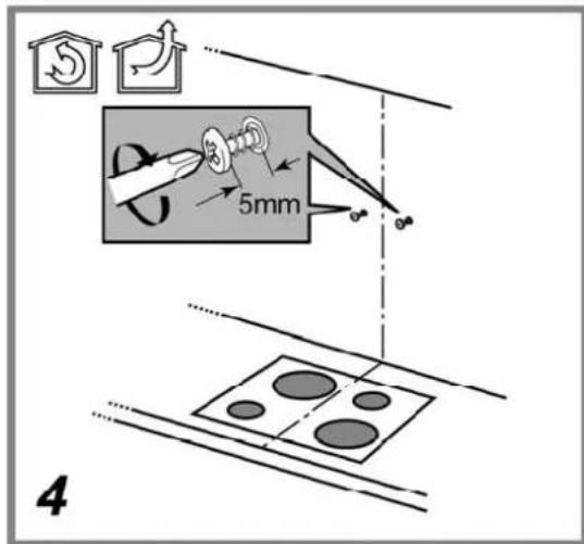
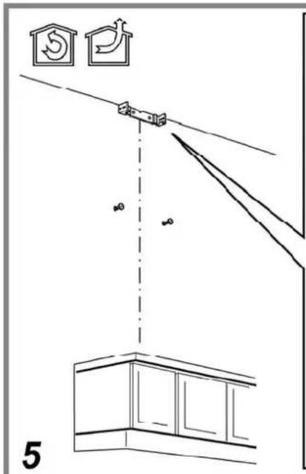
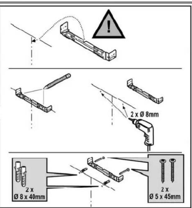
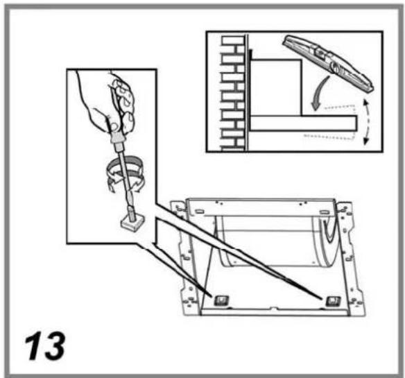
Expansion wall plugs are provided to secure the hood to most types of walls/ceilings. However, a qualified technician must verify suitability of the materials in accordance with the type of wall/ceiling. The wall/ceiling must be strong enough to take the weight of the hood. Do not tile, grout or silicone this appliance to the wall. Surface mounting only.
WARNING! Do not connect the appliance to the mains until the installation is fully complete.
Before any cleaning or maintenance operation, disconnect hood from the mains by removing the plug or disconnecting the mains electrical supply.
Always wear work gloves for all installation and maintenance operations.
The appliance is not intended for use by children or persons with impaired physical, sensorial or mental faculties, or if lacking in experience or know-how, unless they are under supervision or have been trained in the use of the appliance by a person responsible for their safety.
Children should be monitored to ensure that they do not play with the appliance.
This appliance is designed to be operated by adults. Children should not be allowed to tamper with the controls or play with the appliance. Never use the hood without effectively mounted grating!
The hood must NEVER be used as a support surface unless specifically indicated.
The premises where the appliance is installed must be sufficiently ventilated, when the kitchen hood is used together with other gas combustion devices or other fuels.
The suctioned air must not be conveyed into a conduit used for the disposal of the fumes generated by appliances that combust gases or other fuels.
The flaming of foods beneath the hood itself is severely prohibited.
The use of exposed flames is detrimental to the filters and may cause a fire risk, and must therefore be avoided in all circumstances.
Any frying must be done with care in order to make sure that the oil does not overheat and burst into flames.
With regards to the technical and safety measures to be adopted for fume discharging it is important to closely follow the regulations provided by the authorised authorities.
The hood must be regularly cleaned on both the inside and outside (AT LEAST ONCE A MONTH).
This must be completed in accordance with the maintenance instructions provided in this manual). Failure to follow the instructions provided in this user guide regarding the cleaning of the hood and filters will lead to the risk of fires.
Do not use or leave the hood without the lamp correctly mounted due to the possible risk of electric shocks.
We will not accept any responsibility for any faults, damage or fires caused to the appliance as a result of the non-observance of the instructions included in this manual.
ELECTRICAL CONNECTION
The mains power supply must correspond to the rating indicated on the plate situated inside the hood. If provided with a plug connect the hood to a socket in compliance with current regulations and positioned in an accessible area. If it not fitted with a plug (direct mains connection) or if the plug is not located in an accessible area apply a double pole switch in accordance with standards which assures the complete disconnection of the mains under conditions relating to over-current category III, in accordance with installation instructions.
Warning! Before re-connecting the hood circuit to the mains supply and checking the efficient function, always check that the mains cable is correctly assembled.
Replacing the power cable
The hood is provided with a special power cable; if the cable is damaged, request a new one from Technical Service.
AIR VENT
(for the suction versions)
Connect the hood and discharge holes on the walls with a diameter equivalent to the air outlet (connection flange).
Using the tubes and discharge holes on walls with smaller dimensions will cause a diminution of the suction performance and a drastic increase in noise.
Any responsibility in the matter is therefore declined.
! Use a duct of the minimum indispensable length.
! Use a duct with as few elbows as possible (maximum elbow angle: 90°).
! Avoid drastic changes in the duct cross-section.
! Use a duct with an as smooth as possible inside.
! The duct must be made of certified material.
! The company declines any responsibility whenever these regulations are not respected.
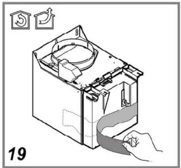
FILTERING OR DUCTING ?
! Your cooker hood is ready to be used in suction version.
To use the hood in filtering version the special ACCESSORY KIT must be installed.
Check on the first pages of this manual if the ACCESSORY KIT is furnished or must be bought separately.
Note: If furnished, in certain cases, the additional activated carbon filtering system may be installed on the hood.
Information about the conversion of the hood from suction version to filtering version is present in this manual.

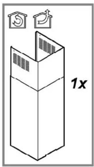
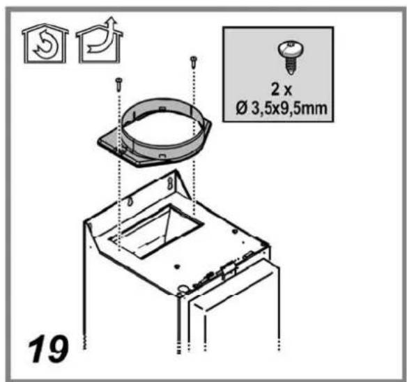
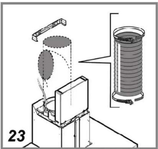
Ducting version
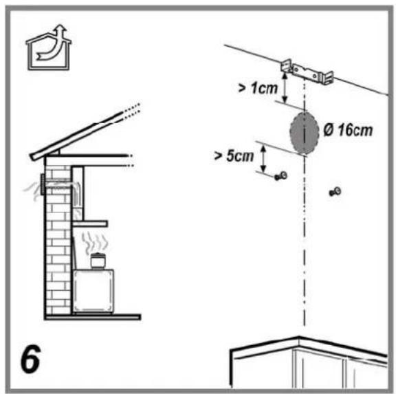
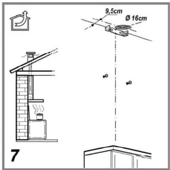
In this case the fumes are conveyed outside by means of a special pipe connected with the connection ring located on top of the hood.
Attention! The exhausting pipe is not supplied and must be purchased apart.
Diameter of the exhausting pipe must be equal to that of the connection ring = 150mm.
In the horizontal runs the exhausting pipe must be slightly slanted (about 10^ ) and directed upwards to vent the air easily from the room to the outside.
Attention! If the hood is supplied with active charcoal filter, then it must be removed.

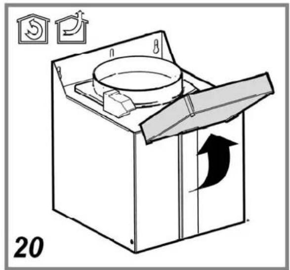
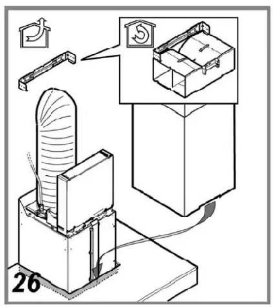
Filter version
One active charcoal filter is needed for this and can be obtained from your usual retailer.
The filter removes the grease and smells from the extracted air before sending it back into the room through the upper outlet grid.
CONTROLS
The control switches are located on the hood's front panel. To select the functions of the hood just touch the commands.

- ON/OFF/Stand-By key
Press shortly to set the hood to "Stand-by" (led "b" on), press longer (min 2 seconds) to turn off completely (OFF – all functions disabled except lighting).
Press again (min 2 seconds) to re-set the hood to "Stand-by".
- Light ON/OFF key
- Display
- Speed selection key 1-2-3-1-2.....
- Intense speed ON/OFF key. Time - 5 minutes, the letter P and the residual operation time appear in the display, the led "a" flashes.
After the 5 operation minutes, the hood goes back to the previously set speed.
Press key 1 or 5 to deactivate this function before the time.
- Timer ON/OFF key: it times all the speeds (led "b" flashing), then the hood turns off:
1^a speed: 20 minutes
2^a speed: 15 minutes
3^a speed: 10 minutes
The display shows the residual operation time.
Press key 6 to deactivate this function before the time.
In case the hood or the controls do not work, it is recommended to cut off power supply for at least 5 seconds and then turn it on again. Wait for 15 seconds and check if the hood works properly.
Signalling of the saturation of the anti-grease filter (F) and the carbon filter (C)
This type of hood is equipped with a device which signals when the following maintenance operations must be carried out:
Grease filter/s - the letter F flashes on the display
Carbon filter – the letter C flashes on the display.
Signalling of the saturation of the carbon filter is normally deactivated.
To activate it, proceed as follows
Press key 1 shortly to set the hood to "Stand-by".
Keep keys 4 and 5 pressed contemporaneously for three seconds.
At first the letter F appears on the display, then the letter C appears to indicate that the signalling of the saturation of the carbon filter is activated
After clearing or replacing the filter, press key 1 for 3 seconds until the letter F (anti-grease filter/s) and/or the letter C stop/s flashing.
MAINTENANCE
ATTENTION! Before performing any maintenance operation, isolate the hood from the electrical supply by switching off at the connector and removing the connector fuse.
Or if the appliance has been connected through a plug and socket, then the plug must be removed from the socket.
Cleaning
The cooker hood should be cleaned regularly (at least with the same frequency with which you carry out maintenance of the fat filters) internally and externally. Clean using the cloth dampened with neutral liquid detergent. Do not use abrasive products. DO NOT USE ALCOHOL!
WARNING: Failure to carry out the basic cleaning recommendations of the cooker hood and replacement of the filters may cause fire risks.
Therefore, we recommend oserving these instructions.
The manufacturer declines all responsibility for any damage to the motor or any fire damage linked to inappropriate maintenance or failure to observe the above
safety recommendations.
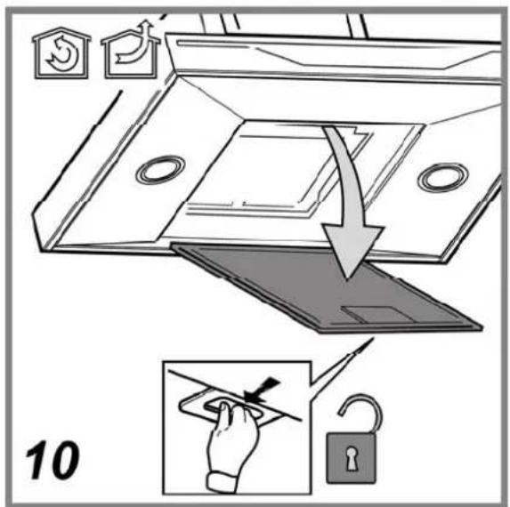
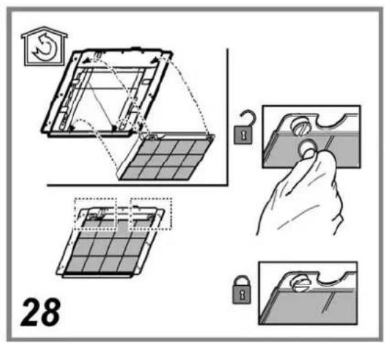
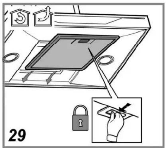
Maintenance of the anti-grease filters
Traps cooking grease particles.
This must be cleaned once a month using non aggressive detergents, either by hand or in the dishwasher, which must be set to a low temperature and a short cycle. When washed in a dishwasher, the grease filter may discolour slightly, but this does not affect its filtering capacity.
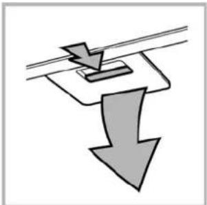
To remove the grease filter, pull the spring release handle.
natural_image
Diagram showing a downward arrow and a rectangular object on a horizontal line, no text or symbols presentMaintenance of the charcoal filter
It absorbs unpleasant odours caused by cooking.
The saturation of the activated charcoal occurs after more or less prolonged use, depending on the type of cooking and the regularity of cleaning of the grease filter.
In any case it is necessary to replace the cartridge at least every four mounths.
The carbon filter may NOT be washed or regenerated.
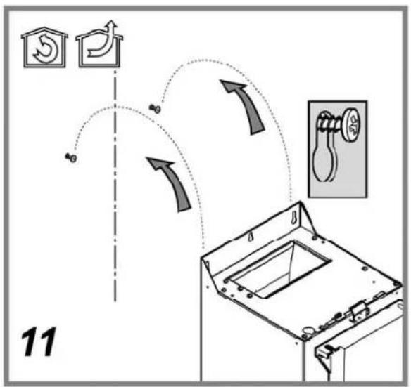
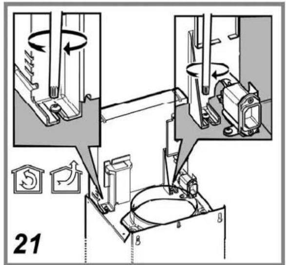
Assembly
Hook the charcoal filter at the back on the metal tongue of the hood first, then on the front with the two knobs.
Disassembly
Remove the charcoal filter by turning the knobs fixing it to the hood by 90°.

EN
Replacing lamps
Disconnect the hood from the electricity.
Warning! Prior to touching the light bulbs ensure they are cooled down.
- Using a flat head screwdriver or equivalent tool, carefully pry loose the light cover.
- Remove the damaged light and replace with a new 12 Volt, 20 Watt (Maximum) halogen light made for a G-4 base SUITABLE FOR USE IN OPEN LUMINAIRES. Follow package directions and do not touch new light with bare hands.
- Reinstall the light cover. (it will snap shut).

natural_image
Illustration of a hand holding a compass and a magnifying glass, with no text or symbols present.DISPOSAL
This appliance is marked according to the European directive 2002/96/EC on Waste Electrical and Electronic Equipment (WEEE). By ensuring this product is disposed of correctly, you will help prevent potential negative consequences for the environment and human health, which could otherwise be caused by inappropriate waste handling of this product.

The symbol ■ on the product, or on the documents accompanying the product, indicates that this appliance may not be treated as household waste. Instead it should be taken to the appropriate collection point for the recycling of electrical and electronic equipment. Disposal must be carried out in accordance with local environmental regulations for waste disposal.
For more detailed information about treatment, recovery and recycling of this product, please contact your local authority.
MALFUNCTIONS
If something appears not to be working properly, do the following simple checks before calling Technical Service:
• If the hood is not working:
Check that:
- The power has not been disconnected.
- A speed has been selected.
• If the hood performs inefficiently:
Check that:
- The motor speed selected is sufficient for the amount of smoke and vapours released.
- The kitchen is sufficiently ventilated to allow air intake.
- The charcoal filter is not worn (hood in filtering version).
- If the hood has turned off during normal functioning:
Check that:
- The power has not been disconnected.
- the omnipolar disconnection device has not tripped.
If the hood fails to operate correctly, briefly disconnect it from the mains power supply for almost 5 sec. by pulling out the plug. Then plug it in again and try once more before contacting the Technical Assistance Service.
TECHNICAL DATA
Model HSB 99 CL
Model HSB 99 IX
Height 72-114 cm
Width 89,8 cm
Depth 45 cm
Gross weight:HSB 99 IX: 25,2 Kg
Gross weight HSB 99 CL: 28 Kg
Total absorption 215 W
Motor absorption 1x175 W
Lamp absorption 2x20 W (G4)
Exhaust pipe ∅ 15 cm
Model HSD 69 IX
Height 72-114 cm
Width 59,8 cm
Depth 45 cm
Gross weight: 19,5 Kg
Total absorption 215 W
Motor absorption 1x175 W
Lamp absorption 2x20 W (G4)
Exhaust pipe ∅ 15 cm
This appliance conforms to the following EEC Directive:
• "Low Voltage Equipment" Directive 2006/95/EC (12-12-2006)
• "Electromagnetic Compatibility" Directive 2004/108/EC (15-12-2004)

Components not provided with the product
natural_image
Diagram showing a downward arrow with a rectangular object inserted into a pipe (no text or symbols)natural_image
Illustration of a hand holding a compass and a magnifying glass, with no text or symbols present.ÉLIMINATION
Absorption ampoule 2x20 W (G4)
Absorption ampoule 2x20 W (G4)
natural_image
Diagram showing a downward arrow and a rectangular object on a horizontal line, no text or symbols presentNL
Vervanging lampjes
Sluit de stroom af.
natural_image
Illustration of a hand holding a compass and a small blue component, with no text or symbols present.VERWIJDERING
natural_image
Diagram showing a downward arrow and a rectangular object on a horizontal line, no text or symbols presentnatural_image
Illustration of a hand holding a compass and a magnifying glass, with no text or symbols present.SMALTIMENTO
• "Low voltage" Directive 2006/95/EC (12-12-2006)
• "EMC" Directive 2004/108/EC (15-12-2004)

natural_image
Diagram showing a downward arrow with a small object above it, no text or symbols presentRU
Замена ламп
natural_image
Illustration of a hand holding a compass and a magnifying glass, with no text or symbols present.УТИЛИЗАЦИЯ
- Ersetzen der Lampen
- ENTSORGUNG
- GENERAL SAFETY
- ELECTRICAL CONNECTION
- Replacing the power cable
- AIR VENT
- FILTERING OR DUCTING ?
- Ducting version
- Filter version
- CONTROLS
- Signalling of the saturation of the anti-grease filter (F) and the carbon filter (C)
- Signalling of the saturation of the carbon filter is normally deactivated.
- MAINTENANCE
- Cleaning
- Maintenance of the anti-grease filters
- Traps cooking grease particles.
- Maintenance of the charcoal filter
- It absorbs unpleasant odours caused by cooking.
- Assembly
- Disassembly
- EN
- Replacing lamps
- DISPOSAL
- MALFUNCTIONS
- TECHNICAL DATA
- Model HSD 69 IX
- ÉLIMINATION
- NL
- Vervanging lampjes
- VERWIJDERING
- SMALTIMENTO
- RU
- Замена ламп
- УТИЛИЗАЦИЯ
Brand : SCHOLTES
Model : HSB 99
Category : Range hood