ISW670RVS - Basket Pelgrim - Free user manual and instructions
Find the device manual for free ISW670RVS Pelgrim in PDF.

User questions about ISW670RVS Pelgrim
0 question about this device. Answer the ones you know or ask your own.
Ask a new question about this device
Download the instructions for your Basket in PDF format for free! Find your manual ISW670RVS - Pelgrim and take your electronic device back in hand. On this page are published all the documents necessary for the use of your device. ISW670RVS by Pelgrim.
USER MANUAL ISW670RVS Pelgrim
Order with this exhaust hood charcoal filter KF66/P01
ATTENTION!
Ordre les filtres à charbon actif KF66/P01 pour cette hotte aspirante ACHTUNG! Bestellen Sie Kohlefilter KF66/P01 für diese Dunstabzugshaube
88022596

natural_image
Close-up of a metallic ventilation grille with mounting holes and ventilation slots (no text or symbols visible)ISW670RVS
Pelgrim
Handleiding
Notice d'utilisation - Anleitung - Manual
NL
Handleiding 3 - 12
FR
text_image
Technical diagram showing two mechanical or electrical installation setups with labeled components and directional arrows indicating motion.3 Gebruik

Bediening

text_image
示 01 2 3 1 2 3 4 5 3natural_image
Diagram of a mechanical component with internal slots and an arrow indicating rotation (no text or symbols)natural_image
Pure technical diagram of a rectangular structure with internal components and a labeled point A (no text or symbols beyond label)natural_image
Technical diagram showing layered circular components with labeled section A (no text or symbols beyond label)
4 Onderhoud

4.4 Reinigen
Afzuigkap
natural_image
Mechanical assembly diagram showing a component mounted on a base plate with two upward arrows indicating motion or force directions (no text or symbols present)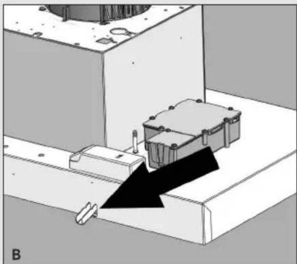
natural_image
Technical diagram showing a mechanical assembly with a black arrow indicating direction, no visible text or symbols
natural_image
Diagram of a mechanical component with an arrow indicating direction, no visible text or symbolsnatural_image
Symbol of a trash bin with crossed lines indicating no waste or discharge (no text or labels)natural_image
Two technical diagrams showing mechanical assembly or lifting process with arrows indicating motion (no text or symbols)3 Utilisation

Commande

text_image
示 01 2 3 1 2 3 4 5 3natural_image
Diagram of a mechanical component with internal grooves and a central knob, showing motion direction (no text or symbols)natural_image
Pure technical diagram of a rectangular structure with internal channels and an arrow, no text or symbols presentnatural_image
Technical diagram showing three circular components labeled A, with no visible text or symbols beyond the label.
4 Entretien

4.4 Nettoyage
Hotte
natural_image
Technical diagram of a mechanical assembly with mounting holes and internal components, no visible text or symbols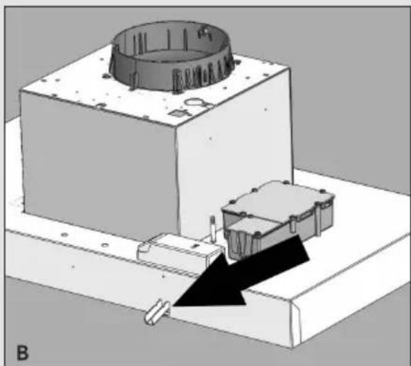
natural_image
3D mechanical assembly diagram showing a housing with a circular component and a base plate, no visible text or symbols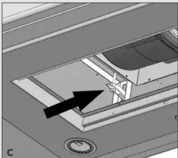
natural_image
Interior view of a vehicle cabin with a black arrow pointing to the interior space (no text or symbols visible)natural_image
Symbol of a trash bin with crossed x-marks and a blank base (no text or numbers)text_image
Technical diagram showing two mechanical or electrical installation setups with labeled components and directional arrows indicating motion.Bedienung
text_image
示 01 2 3 1 2 3 4 5 3natural_image
Diagram of a mechanical component with internal slots and a central knob, showing motion direction (no text or symbols)natural_image
Pure technical diagram of a rectangular panel with internal structure and labeled point A (no text or symbols beyond label)natural_image
Technical diagram showing two circular components labeled A, with no visible text or symbols
4.4 Reinigen
Dunstabzugshaube
natural_image
Technical diagram of a mechanical assembly with two upward arrows indicating motion or force directions (no text or symbols present)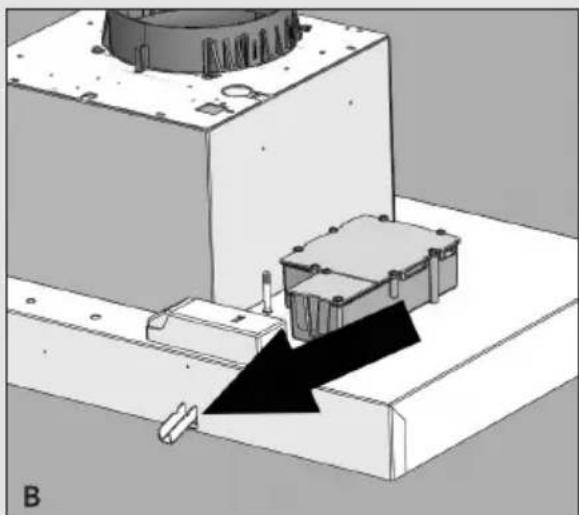
natural_image
Mechanical assembly diagram showing a rotating component mounted on a base with a black arrow indicating motion direction (no text or symbols)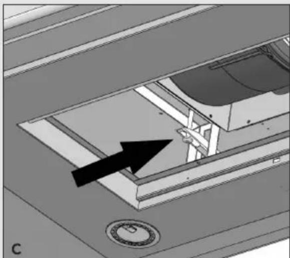
natural_image
Technical diagram of a mechanical component with an arrow indicating direction, no visible text or symbolsnatural_image
Symbol of a trash bin with crossed lines indicating no waste or discharge (no text or labels)2.1 Precautions you must take 35
2.2 Extraction systems 36
3 Use 37
4 Maintenance
4.1 Removing the grease filter 38
4.2 Replacing the carbon filter 38
4.3 Changing the halogen lamps 38
4.4 Cleaning 39
5 Installation
5.1 General 40
5.2 Mounting the cooker hood 41
6 Appendice 42
1 Your cooker hood

text_image
示 01 2 3 1 2 3 4 5 31.1 Description
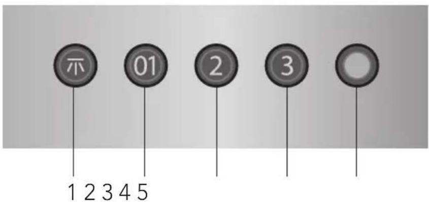
Lightning1.
On/off, fan setting 12.
Fan setting 23.
Fan setting 34.
Indicatorlight5.
1.2 Introduction
When you have read these instructions for use, you will quickly be aware of all the facilities the appliance can offer you. You can read about safety and how you should look after the appliance.
Keep the instructions for use and the installation instructions. Any later user of this appliance could benefit from them.
2 Safety

2.1 What you need to take into account

Attention! Make sure the appliance is installed by an authorised installer (see "Installation" chapter). Do not connect the appliance to the flow network before completing the installation.
Connect the appliance in accordance with the applicable regulations in your area.
We advise you to wear protective work gloves during the installation of the exhaust hood due to possible sharp edges.
- The appliance has been manufactured in accordance with the latest safety standards. However we do advise that mentally handicapped, disabled or retarded individuals do not use this appliance without the proper supervision of a competent person. The same applies to children.
Never use the exhaust hood when the grease filter has not been properly installed! • Do not lean against the exhaust hood. •
Make sure there is sufficient circulation when you use the exhaust hood on a gas cooker.
The exhaust exit must never be connected to a smoke duct which is also used for other heating appliances.
Never flambé under the exhaust hood and always clean the filters on time. Frying needs to be done under constant supervision to prevent the heated fat from catching fire.
The exhaust hood needs to be cleaned regularly (at least once a month) on the • inside as well as on the outside. When the filters are insufficiently cleaned or replaced, this will result in a fire hazard.
If the connection cable becomes damaged, it should be replaced by the manufacturer's service department or by a person with equivalent qualifications, in order to prevent dangerous situations from arising.
- First disconnect the appliance from the socket when you replace the lights! Only use identical lamps with the wattage indicated. Only use the exhaust hood with lamps installed to reduce the risk of electrical shock.
- The grease filters become hot during operation. Wait a minimum of 30 minutes after cooking before cleaning it.
2 Safety

The main current must be switched off during reparation or cleaning. Remove the plug from the mains current or turn the switch in the meter cupboard to zero.
Grease and oil are flammable when they are overheated. Stay in the vicinity of the cooker when preparing food
This appliance is marked in accordance with European guideline regarding the disposal of electrical and electronic appliances (AEEA). This product should be disposed of in accordance with the local environmental regulations for disposal of waste. For further information regarding the treatment, recovery and recycling of this product you can contact your local council, the household waste service or the shop where you purchased the product.
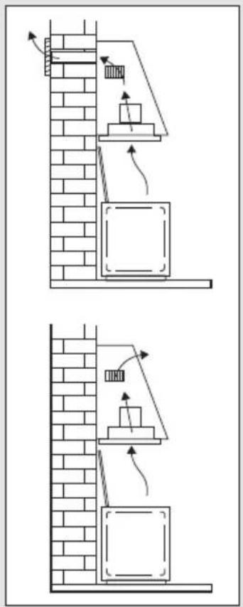
2.2 Extraction systems
Depending on the type, the cooker hoods can be connected in one of two ways:
-
To a duct. To a duct, the cooking vapours extracted by suction are carried outside, once the grease particles have been filtered. This is the best method.
-
Recirculation hood. As a recirculation hood, the grease particles and the smell in the extracted vapours are filtered. The air that has been sucked in is not carried outside but recirculates in the kitchen. In this case you must have a carbon filter fitted.
Attention! The carbon filter needs to be ordered separately.
text_image
Technical diagram showing two mechanical or structural assembly configurations with labeled components and directional arrows indicating motion.Controls

text_image
示 01 2 3 1 2 3 4 5 3Switching the fan on and off
Press the button (2).
The extractor hood switches on or off. The indicatorlight ⑤ indicates that the fan is working.
Press the button (3) or (4).3
The extractor hood switches on at the setting selected.
Switching lighting on and off
Press the lighting button (1).
The lighting switches on.
Press the button again and the lighting goes out.
4 Maintenance
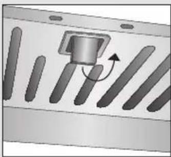
4.1 Removing the grease filter
Switch off the electricity! Remove the plug from the socket or switch the electricity off at the mains. Push the special filter handle towards you and turn it downwards at the front.
natural_image
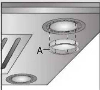
Diagram of a mechanical component with internal grooves and a central knob, showing motion direction (no text or symbols)4.2 Replacing the carbon filter
The carbon filter must always be used if the cooker hood is not ducted.
Note:
Saturation of the activated charcoal will eventually occur after more or less prolonged use, depending on the type of cooking and how frequently the grease filter is cleaned.
In all cases it is necessary to replace the cartridge at least every four months.
DO NOT wash or reuse the carbon filter. Saturated carbon is not environmentally friendly, change the filter regularly.
Fix the carbon filter underneath the motor housing using the plastic clips (A).
Replace the grease filter in the extractor hood.
natural_image
Pure technical diagram of a rectangular panel with internal channels and a labeled component 'A' (no text or symbols beyond label)4.3 Changing the halogen lamps
First remove the glass-blocking ring (A) by levering it with a screw-driver. When performing this operation hold the opaque glass carefully. Remove the lamp (without touching it with uncovered hands) and replace it with another lamp of the same kind (max. 20 Watt). Re-insert the glass and the glass-blocking ring and fasten it.
natural_image
Technical diagram showing two circular components labeled A, with no visible text or symbols
4 Maintenance

4.4 Cleaning
Cooker hood
Clean the cooker hood with soapy water and a soft cloth. Then wipe with clean water to rinse. Do not use aggressive cleaning agents such as soda.

Stainless steel
Do not use any sort of scourer. Treat with a Stainless Steal Cleaner and polish with the structure of the stainless steel.
Metal grease filter
The grease filters can be placed in the dishwasher for cleaning. The openings must be placed downwards to let the water run out of the filters.
5 Installation
5.1 General
This appliance should be connected to the power supply by a recognized fitter who is familiar with, and works according to the correct safety regulations. This appliance meets the European requirements.
Important that you know:
The minimum distance between the supporting surface for the cooking vessels on • the hob and the lowest part of the range hood must be not less than 65 cm from electric cookers and 75 cm from gas or mixed cookers.
If the cooker hood is to be fitted to an existing duct no other appliances, such as a • geyser or heater, may be connected to that same duct.
Consider local regulations with respect to the ventilation of gas appliances.
The shorter the duct, and the fewer the bends in it, the better the cooker hood will work.
The connecting pipe for the cooker hood has a diameter of 125 mm or 150 mm. It is best also to use a flue pipe of the same diameter.
5 Installation

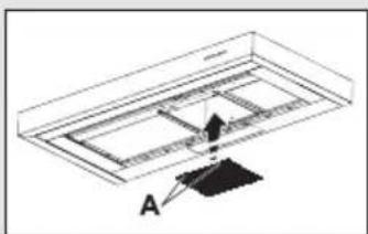
5.2 Mounting the cooker hood
Remove the grease filter.
Make a hole in the mounting panel: • 680 x 371 mm.
Take care that there is at least 60 mm of material around the hole in order to avoid any damage during the following installation.
Adjust the position of the lateral springs making attention of the thickness of the material you are using to fix the unit.
Insert the unit from below (see fig. A). The springs, previously adjusted, are strong enough to keep the product fixed for a while.
Insert the four blocking levers into the holes (see fig. B).
Fix the blocking levers using the screws (see fig. C).
Attention! Do not tighten the screws too much otherwise the planarity of the frame could be compromised.
Mount the grease filter again.

natural_image
Technical diagram of a mechanical assembly with arrows indicating direction (no text or symbols present)
natural_image
Technical diagram of a mechanical assembly with a black arrow indicating direction (no text or symbols present)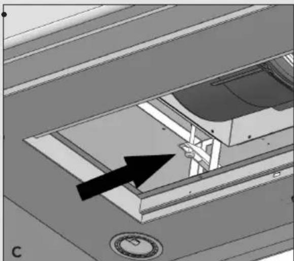
natural_image
Technical diagram showing a mechanical component with an arrow pointing to a specific part (no text or symbols present)6 Appendice

Disposal of appliance and packaging
By ensuring this product is disposed of correctly, you will help prevent potential negative consequences for the environment and human health, which could otherwise be caused by inappropriate waste handling of this product. The local authorities can provide you with the relevant information.
The packaging of this appliance is recyclable. It could have been made from:
cardboard; •
polythene foil (PE); •
CFK-free polystyrene (PS-hard foam). •
You need to dispose of these materials responsibly in accordance with official regulations.
To draw attention to the fact that the segregated processing of electric household appliances is compulsory, this appliance carries the symbol of a crossed-out dustbin. This means that at the end of its working life, you may not dispose of the appliance as household refuse. Instead, you should hand it in at a special refuse collection centre run by the local authority or at a dealer's providing this service.
natural_image
Symbol of a trash bin with crossed lines indicating no waste or discharge (no text or numbers present)Segregated processing of household appliances avoids any negative effects on the environment and public health that might otherwise occur.
It enables the recovery of the materials used in the production of this appliance, thus realising considerable savings in terms of raw materials and energy.