RX-DP20 - AV receiver JVC - Free user manual and instructions
Find the device manual for free RX-DP20 JVC in PDF.

| Product type | Audio-video receiver |
| Brand | JVC |
| Model | RX-DP20 |
| Dimensions (W x H x D) | 445 mm x 177 mm x 475 mm |
| Weight | 23.5 kg |
| Power supply | 120 V AC, 60 Hz |
| Power consumption (operation) | 580 W |
| Power consumption (standby) | 2.7 W |
| Output power (stereo) | 120 W per channel (8 Ω, 20 Hz – 20 kHz, 0.02 % THD) |
| Output power (surround) | 120 W per channel (7 channels, 8 Ω, 20 Hz – 20 kHz, 0.02 % THD) |
| THX certification | THX Ultra2 |
| Supported audio formats | Dolby Digital EX, Dolby Pro Logic II, DTS-ES, DTS NEO:6, DTS 96/24 |
| Digital audio processor | DAP 7.1 channels |
| Audio converter | 192 kHz / 24 bits (DD PCM) |
| Exclusive technologies | K2, CC Converter, ZIST |
| Multi-room function | Independent Zone 2 (speakers or preamp) |
| Remote control systems | COMPU LINK, TEXT COMPU LINK, AV COMPU LINK |
| Digital inputs | 3 coaxial, 3 optical (1 front) |
| Digital output | 1 optical |
| Video inputs | Composite, S-video, component (3 inputs, 1 output) |
| Speaker connectivity | Front 1, Front 2/Zone 2, Center, Surround, Surround back |
| Preamp outputs | Front, Subwoofer, Center, Surround, Surround back, Zone 2 |
| Tuner | FM (87.5 – 108 MHz) and AM (530 – 1710 kHz) |
| Safety | Do not open, avoid moisture, turn off before cleaning, use a soft dry cloth |
| Included accessories | Remote control, batteries, AM and FM loop antennas, RF rod antenna, IR emitter, adhesive tape, cover for plugs, power cord |
Frequently Asked Questions - RX-DP20 JVC
User questions about RX-DP20 JVC
0 question about this device. Answer the ones you know or ask your own.
Ask a new question about this device
Download the instructions for your AV receiver in PDF format for free! Find your manual RX-DP20 - JVC and take your electronic device back in hand. On this page are published all the documents necessary for the use of your device. RX-DP20 by JVC.
USER MANUAL RX-DP20 JVC
MANUEL D'INSTRUCTIONS
For Customer Use:
Enter below the Model No. and Serial No. which are located either on the rear, bottom or side of the cabinet. Retain this information for future reference.
Model No.
Serial No.
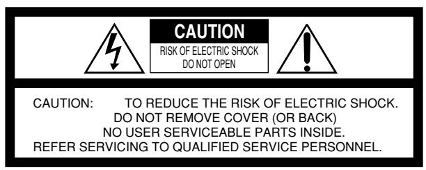
The lightning flash with arrowhead symbol, within an equilateral triangle is intended to alert the user to the presence of uninsulated "dangerous voltage" within the product's enclosure that may be of sufficient magnitude to constitute a risk of electric shock to persons.

The exclamation point within an equilateral triangle is intended to alert the user to the presence of important operating and maintenance (servicing) instructions in the literature accompanying the appliance.
WARNING: TO REDUCE THE RISK OF FIRE OR ELECTRIC SHOCK, DO NOT EXPOSE THIS APPLIANCE TO RAIN OR MOISTURE.
CAUTION
To reduce the risk of electrical shocks, fire, etc.:
- Do not remove screws, covers or cabinet.
- Do not expose this appliance to rain or moisture.
ATTENTION
Disconnect the mains plug to shut the power off completely. The | / |. (STANDBY/ON) switch in any position does not disconnect the mains line. The power can be remote controlled.
Attention—Commutateur /| (STANDBY/ON)!
To avoid personal injury or accidentally dropping the unit, have two persons unpack, carry, and install the unit.
ATTENTION!
This device complies with RSS-210 of Industry Canada Rules. Operation is subject to the following two conditions: (1) this device may not cause interference, and (2) this device must accept any interference, including interference that may cause undesired operation of the device.
We would like to thank you for purchasing one of our JVC products. Before operating this unit, read this manual carefully and thoroughly to obtain the best possible performance from your unit, and retain this manual for future reference.
Features
THX Ultra2 certified
The newly introduced THX Ultra2 standard ensures the highest sound and picture quality and the most reliable performance by using seven-channel amplification to reproduce multi-channel software. In newly developed THX Ultra2 Cinema Mode and THX Music Mode, all multi-channel software (5.1 channels or more) is automatically detected and proper processing is applied to improve directional and ambient surround information through four surround speakers—two at the side and two at the back.
Compatible with various audio formats including DTS 96/24
RX-DP20VBK allows you to enjoy newly introduced audio formats such as Dolby Digital EX, Dolby Pro Logic II, DTS-ES, DTS NEO:6, and DTS 96/24.
- This unit is also compatible with Dual Mono signals recorded in Dolby Digital and DTS discs.
7.1 channel DAP (Digital Acoustic Processor)
Sound field simulation technology allows precise ambience recreation of existing theaters and halls. Thanks to the high-performance DSP (Digital Signal Processor) and high-capacity memory, you can enjoy 7.1-channel surround by playing 2-channel or multi-channel software.
Multi-channel headphone virtual surround sound—3D HEADPHONE
The built-in headphone virtual surround system is compatible with multi-channel software. You can enjoy a natural surround sound through the headphones.
192 kHz/24 bit PEM DD audio DA converter
The JVC-exclusive converter is now upgraded to be fully compatible with DVD Audio's high specifications. Subtle nuances are accurately reproduced.
K2 Technology
K2 technology has been designed to enable natural audio reproduction, achieving a drastic reduction in digital distortion and creating original sound ambience with high precision.
CC (Compensative Compression) Converter
CC Converter eliminates jitter and ripples, achieving a drastic reduction in digital distortion by processing the digital music data in 24 bit-quantization and by expanding the sampling frequency to 128kHz (for fs 32kHz signals)/176.4 kHz (for fs 44.1kHz signals)/192 kHz (for fs 48kHz signals). By using the CC Converter, you can obtain a natural sound field from any source.
ZIST (Zero Interference audio Signal Transmission) circuit
The ZIST circuit incorporated for the EXT 7.1 CH IN (input) jacks successfully eliminates the video signal interference to the audio signals by making the cold side of the audio signals completely independent from the ground.
Multi-room operations
You can connect two pairs of front speakers to the RX-DP20VBK, and use them to listen to different sources in different rooms (Zone 1 and Zone 2) at the same time.
COMPU LINK/TEXT COMPU LINK/AV COMPU LINK remote control systems
These COMPU LINK remote control systems allow you to operate other JVC audio/video components from this receiver.
Precautions
Power sources
- When unplugging the receiver from the wall outlet, always pull the plug, not the AC power cord.
- Do not handle the AC power cord with wet hands.
- If you are not going to operate the receiver for an extended period of time, unplug the AC power cord from the wall outlet.
Multi-room operations
- Do not use the remote control outdoors or install the speakers outdoors.
-
When operating the receiver from a place where you cannot see the receiver (for example, when controlling the receiver installed in the living room from the kitchen), pay attention to the following not to surprise other people:
-
Be careful not to turn up the volume too high when controlling the receiver without listening to the playback sound.
-
Be careful not to surprise other people with a sudden sound coming out of the receiver when turning it on. (Stopping the sound suddenly may surprise people as well.)
-
If the receiver operates by itself or malfunctions, the following causes should be considered:
-
Interference to RF communication between the receiver and the remote control from outside.
-
The remote control is operated unintentionally. For example, a book is placed on the remote control, possibly, depressing some of its buttons.
-
If your neighbour uses the same or similar RF remote control system, the receiver may happen to receive the RF signals sent from such an RF remote control system, which could cause your receiver to be operated unintentionally. If this happens, set the BAND selectors both on the rear and on the remote control to another band (either BAND 1 or BAND 2)—see page 17 for details.
If the problem still persists, stop using the RF rod antenna and the remote control, and consult your JVC dealer or the nearest JVC Service Center.
Ventilation
The seven high power amplifiers built in this receiver will generate heat inside the cabinet.
For safety, observe the following carefully:
-
Make sure there is good ventilation around the receiver. Poor ventilation could overheat and damage the receiver.
-
Do not block the ventilation openings or holes. (If the ventilation openings or holes are blocked by a newspaper or cloth, etc., the heat may not be able to get out.)
Others
- Should any metallic object or liquid fall onto the unit, unplug the unit and consult your dealer before operating any further.
- Do not use this receiver in a bathroom or places with water.
- Do not place any containers filled with water or liquids (such as cosmetics or medicines, flower vases, potted plants, cups, etc.) on top of this receiver.
- Do not disassemble the unit since there are no user serviceable parts inside.
If anything goes wrong, unplug the AC power cord and consult your JVC dealer.
Parts Identification 3
Getting Started 7
Before Installation 7
Checking the Supplied Accessories 7
Connecting the FM and AM Antennas 7
Connecting the Speakers 8
Connecting Audio/Video Components 11
■ Analog Connections 11
Digital Connections 16
Using the RF Rod Antenna and IR Signal Transmitter 17
Connecting the Power Cord 18
Putting Batteries in the Remote Control 18
Multi-Room Operations 19
Required Connections for Zone 2 19
Basic Operating Procedure for Zone 1 20
Basic Operating Procedure for Zone 2 21
Zone 1 (Main Room) Operations 22
Turning the Power On and Off (Standby) 22
Canceling the Zone 1 Operations 23
Selecting the Zone 1 Source to Play 23
Adjusting the Zone 1 Volume 24
Activating the Zone 1 Front Speakers 25
Selecting the Analog or Digital Input Mode 25
Attenuating the Input Signal 26
Muting the Zone 1 Sound 26
Changing the Display Brightness 27
Turning Analog Direct On and Off 27
Making Sounds Natural 27
Changing the Source Name 27
Using the Sleep Timer 28
Zone 2 (Sub-room) Operations 29
Turning the Power On and Off (Standby) and Selecting the Zone 2 Operations 29
Canceling the Zone 2 Operations 30
Selecting the Zone 2 Source to Play 31
Adjusting the Zone 2 Volume. 31
Activating the Zone 2 Front Speakers 32
Muting the Zone 2 Sound 32
Receiving Radio Broadcasts 33
Tuning in to Stations Manually 33
Using Preset Tuning 34
Selecting the FM Reception Mode 34
Basic Settings 35
Setup Menu Configuration 35
Operation through On-Screen Display Menus 36
Menu Operating Procedure 37
□ Setting the Speakers—SPEAKER SETTING 38
2 Adjusting the Speaker Channel Output Levels CHANNEL LEVEL 38
Setting the Speaker Distance—SPEAKER DISTANCE ... 40
4 Setting the Bass Sounds—SUBWOOFER 40
Setting the THX Audio—THX AUDIO SETUP 41
Setting the Surround Channel Output Speakers
—SURR CH OUT 42
7 Setting the Audio Delay Level—AUDIO DELAY 42
8 Selecting the Dual Mono Sound-DUAL MONO 42
9 Setting the Digital Input/Output Terminals DIGITAL IN/OUT 42
10 Setting the Video Input Terminals—VIDEO INPUT 43
11 Turning On and Off the Video Output—VIDEO POWER 43
12 Setting the Zone 2/Speakers 2 Usage
—ZONE 2/SPEAKER 2 43
13 Superimposing the Menus—SUPERIMPOSE 44
14 Showing the Text Information on the Display FL DISPLAY 44
[15] Memorizing the Volume Level for Each Source
—ONE TOUCH OPE 44
Sound Adjustments 45
Adjustment Menu Configuration 45
Operation through On-Screen Display Menus 46
Menu Operating Procedure 47
1 Adjusting the Parametric Equalizer for Each Channel PEQFRONT/CENTER/SURROUND/SURR BACK. 48
Setting the Midnight Mode—MIDNIGHT MODE 49
3 Adjusting the Various Effects—EFFECT ADJUST 49
Using the Surround and THX Modes 51
Reproducing Theater Ambience 51
Introducing the Surround and THX Modes 51
Surround and THX Modes Applicable to the Various Software .... 53
Activating the Surround and THX Modes 55
Activating the 7.1-channel reproduction 55
Activating the Surround Modes 56
Activating the THX Modes 57
Using the DSP Modes 58
Reproducing the Sound Field 58
Introducing the DSP Modes 58
Activating the DSP Modes 59
Using the Analog Multi-channelPlayback Mode.....60
Activating the Analog Multi-channel Playback Modes 60
COMPU LINK Remote Control System 61
TEXT COMPU LINK Remote Control System .... 63
■ Showing the Disc Information on the TV Screen (Either in Zone 1 or in Zone 2) 64
Searching for a Disc (Only for the CD player) 65
■ Entering the Disc Information 66
AV COMPU LINK Remote Control System .... 68
Operating JVC's Audio/Video Components … 71
Operating Audio Components 71
Operating Video Components 73
Operating Other Manufacturers' Equipment... 74
Changing the Preset Signal Codes 74
Storing the Remote Signals Manually 78
Troubleshooting 81
Specifications 83

Indicates the functions YOU CAN ALSO USE when the receiver is ready for Zone 2 operations.
Front Panel
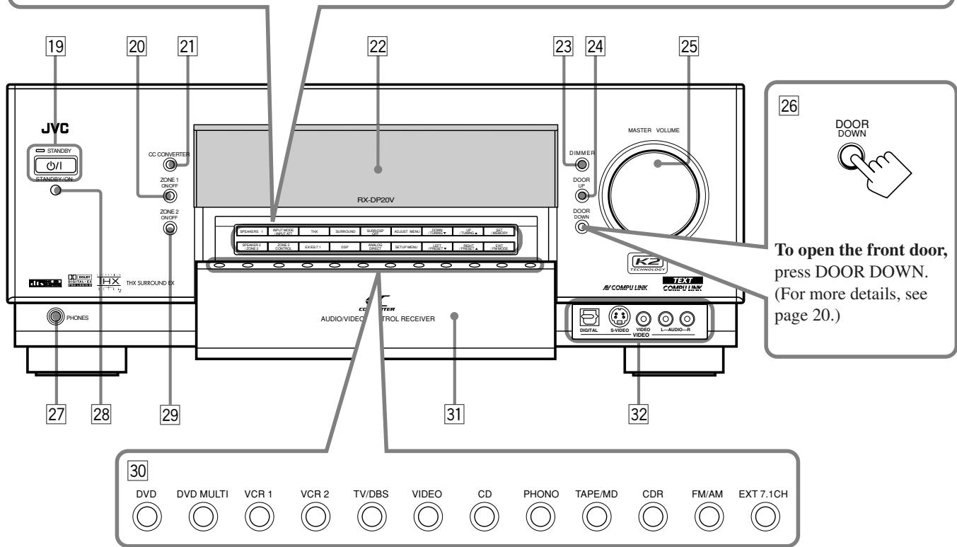
Display Window
Front Panel
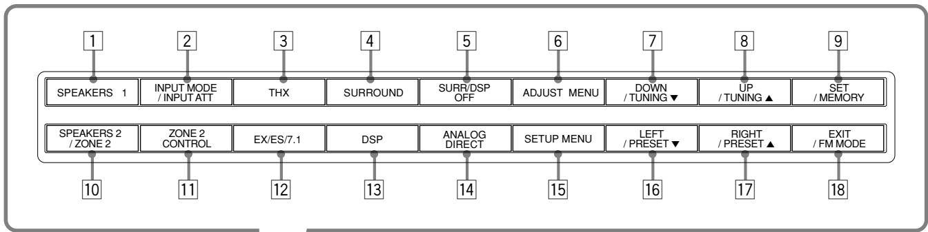
SPEAKERS 1 button (20, 25)
2 INPUT MODE button (25)
INPUT ATT button (26)
THX button (57, 60)
4 SURROUND button (56, 57)
5 SURR/DSP OFF button (56, 57, 59, 60)
6 ADJUST MENU button (46)
DOWN button (36, 46) TUNING button (33)
UP button (36, 46) TUNING button (33)
SET button (36, 46)
MEMORY button (34)
10 SPEAKERS 2 button (20, 25)
ZONE 2 button (32)
11 ZONE 2 CONTROL button (21, 29)
12 EX/ES/7.1 button (55)
DSP button (59)
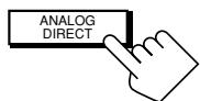
14 ANALOG DIRECT button (27)
15 SETUP MENU button (36)
16 LEFT button (36, 46)
PRESET button (34)
17 RIGHT button (36, 46)
PRESET button (34)
18 EXIT button (36, 46) FM MODE button (34)
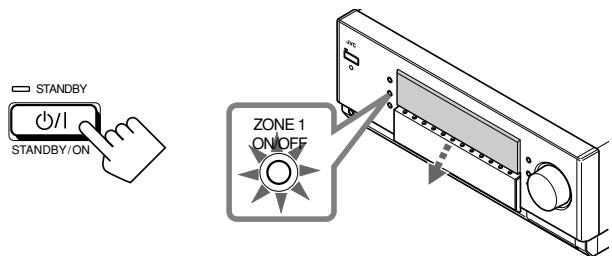
19 0/1 (STANDBY/ON) button and STANDBY lamp (20-22, 29)
• STANDBY lamp lights up in red when the unit is turned off.
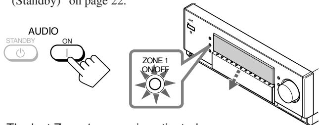
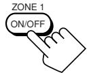
20 ZONE 1 ON/OFF button and lamp (20-22) ZONE 1 ON/OFF lamp lights up in red when Zone 1 is turned on.
21 CC CONVERTER button and lamp (27) CC CONVERTER lamp lights up in red when CC Converter is turned on.
Display
DIMMER button (27)
24 DOOR UP button (20)
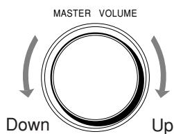
25 MASTER VOLUME control (20, 21, 24, 31)
26 DOOR DOWN button (20)
27 PHONES jack (25)
28 Remote sensor
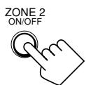
29 ZONE 2 ON/OFF button and lamp (21, 29, 30)
- ZONE 2 ON/OFF lamp lights up in red when Zone 2 is turned on.
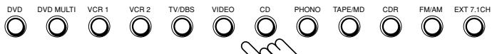
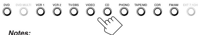
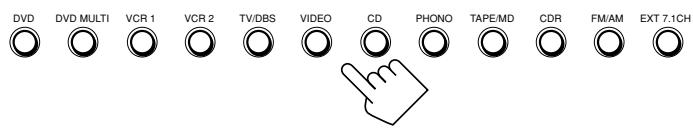
Source selecting buttons (20, 23-25) DVD, DVD MULTI, VCR 1, VCR 2, TV/DBS,VIDEO, CD, PHONO, TAPE/MD, CDR, FM/AM, EXT 7.1CH
31 Front door
VIDEO input terminals (12)
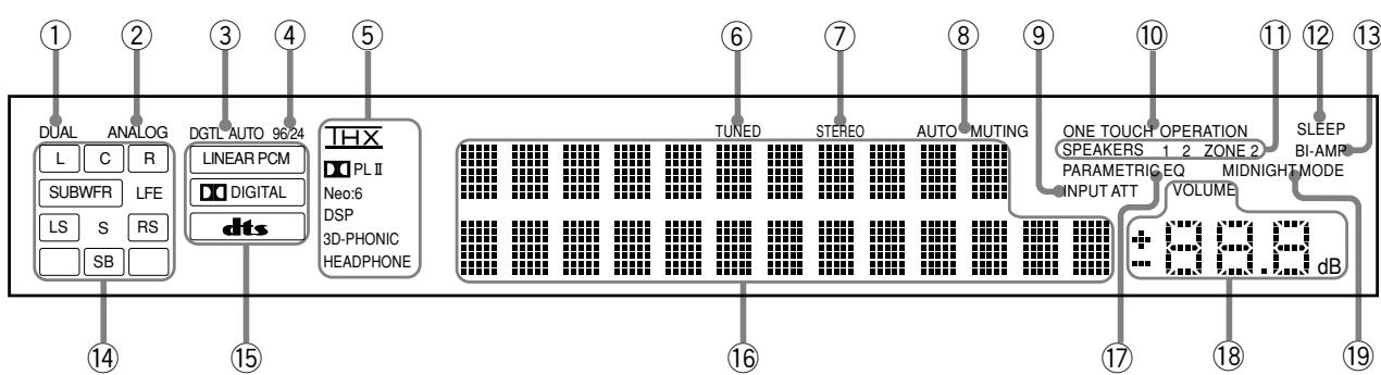
Display Window
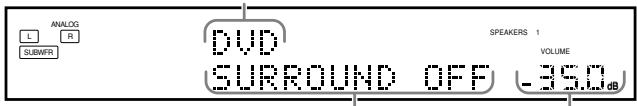
① DUAL indicator (24)
- Lights up when Dual Mono signals are detected.
② ANALOG indicator (26)
- Lights up when an analog input (source) is selected.
③ DGTL AUTO indicator (26)
- Lights up when auto digital input (DIGITAL AUTO) is selected.
④ 96/24 indicator (52)
- Lights up when DTS 96/24 signals are detected.
⑤ Surround/THX/DSP mode indicators
- Indicate the current Surround/THX/DSP mode setting.
⑥ TUNED indicator (33)
- Lights up when a station is received.
⑦ STEREO indicator (33)
- Lights up when an FM stereo station is received.
⑧ AUTO MUTING indicator (34)
- Lights up when the FM station reception mode is set to Auto Reception mode (AUTO MUTING).
INPUT ATT indicator (26)
- Lights up when Input Attenuator is in use.
10 ONE TOUCH OPERATION indicator (44)
- Lights up when One Touch Operation is in use.
⑪ SPEAKERS 1/2/ZONE 2 indicators (32)
- SPEAKERS : Lights up when any of the speakers connected to the FRONT 1 SPEAKERS and the FRONT 2/ ZONE 2 SPEAKERS terminals is activated.
1/2 Lights up when the corresponding speakers are activated for Zone 1.
- ZONE 2 : Lights up when the front speakers connected to the FRONT 2/ZONE 2 SPEAKERS terminals are activated for Zone 2.
⑫ SLEEP indicator (28)
- Lights up when Sleep Timer is in use.
⑬ BI-AMPindicator(44)
- Lights up when "SPEAKER 2" is set to "BI-AMP OUT."
⑭ Speaker and signal indicators (23)
- Speaker indicators : Indicate the activated speakers.
- Signal indicators : Indicate the incoming channel signals.
⑤ Digital signal format indicators (26)
- Indicates the digital signal format of incoming signals.
16 Main display
- Shows the source name, station frequency, Surround/THX/DSP mode, etc.
17 PARAMETRIC EQ indicator (48)
- Lights up when Parametric Equalizer is in use.
VOLUME level indicator
- Indicates the volume level.
- Goes off while muting sounds.
19 MIDNIGHT MODE indicator (49)
- Lights up when Midnight Mode is in use.
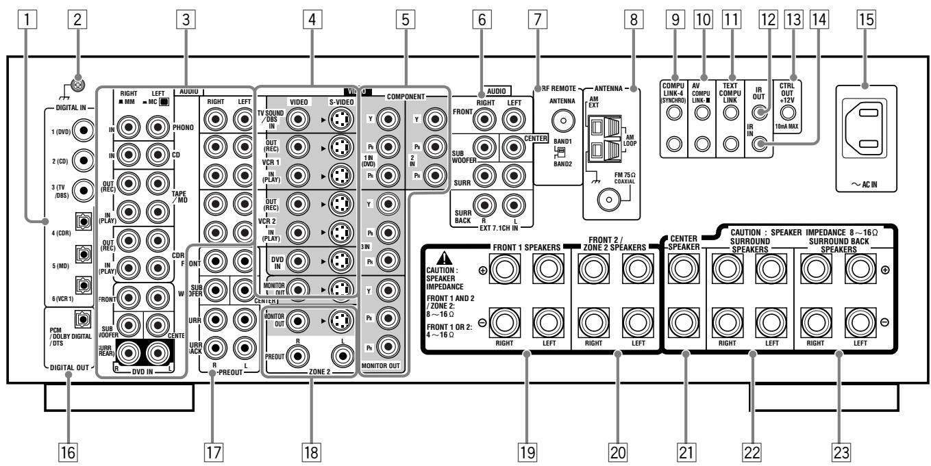
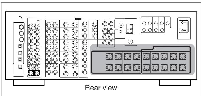
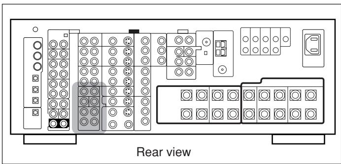
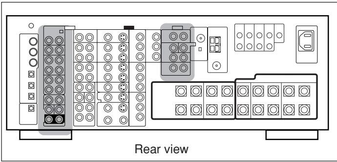
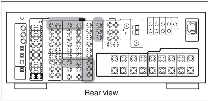
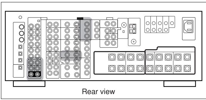
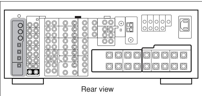
Rear Panel
DIGITAL IN terminals (16)
Coaxial: 1 (DVD), 2 (CD), 3 (TV/DBS)
- Optical: 4 (CDR), 5 (MD), 6 (VCR 1)
2 Earth (ground) terminal (11)
3 Audio input/output jacks (13-15)
- Input: PHONO IN, CD IN, TAPE/MD IN, CDR IN TV SOUND/DBS IN, VCR 1 IN, VCR 2 IN, DVD IN (5.1 ch)
Output: TAPE/MD OUT, CDR OUT VCR 1 OUT, VCR 2 OUT
4 S-video/composite video input/output jacks (13-15)
- Input: TV SOUND/DBS IN, VCR 1 IN, VCR 2 IN, DVD IN
Output: VCR 1 OUT, VCR 2 OUT, MONITOR OUT
[5] Component video input/output jacks (13-15)
- Input: 1 IN (DVD), 2 IN, 3 IN
Output: MONITOR OUT
EXT 7.1CH IN (audio input) jacks (12)
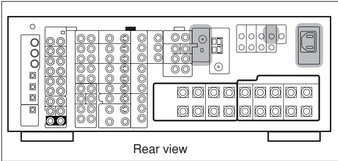
RF REMOTE ANTENNA terminal and BAND 1/2 selector (17)
FM/AM ANTENNA terminals (7,8)
9 COMPU LINK-4 (SYNCHRO) terminals (61, 63)
10 AV COMPU LINK-III terminals (68)
TEXT COMPULINK terminals (63)
12 IR OUT terminal (18, 68)
13 CTRL OUT +12V terminal
- This terminal is only for service use.
14 IR IN terminal
- This terminal is only for service use.
15 AC IN socket (18)
DIGITAL OUT terminal (16)
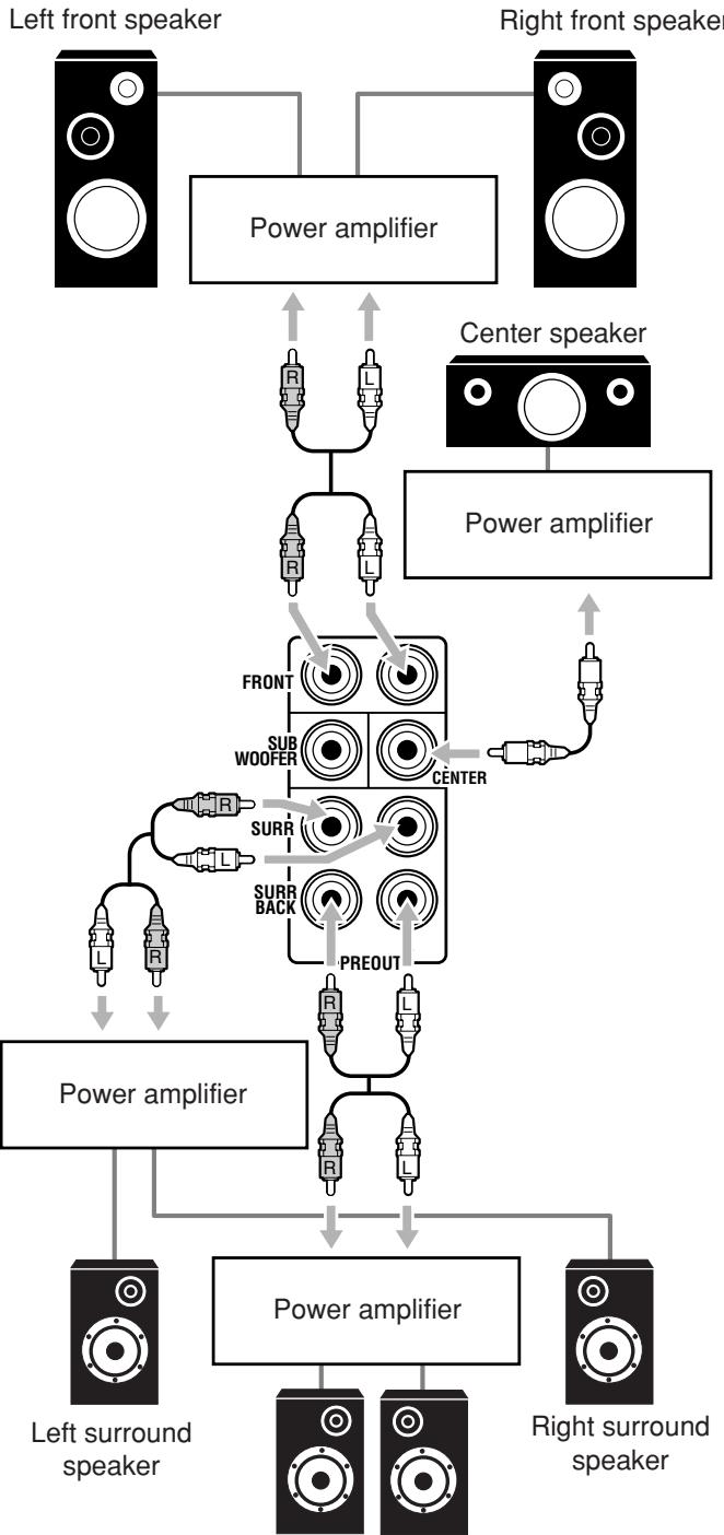
PREOUT jacks (10)
- FRONT, SUBWOOFER, CENTER, SURR, SURR BACK
18 ZONE 2 audio/video output jacks (19)
Audio output: PREOUT
Video output: MONITOR OUT (S-video/composite video)
FRONT 1 SPEAKERS terminals (9)
20 FRONT 2/ZONE 2 SPEAKERS terminals (9, 19)
21 CENTER SPEAKER terminals (9)
22 SURROUND SPEAKERS terminals (9)
23 SURROUND BACK SPEAKERS terminals (9)
Remote Control
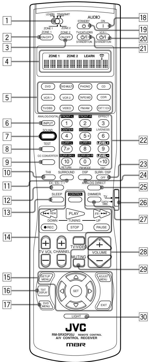
Remote's display window
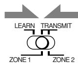
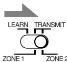
1 ZONE 1/ZONE 2 (LEARN/TRANSMIT) selector
2 ZONE 1 ON/OFF button (23)
3 ZONE 2 ON/OFF button (30)
4 Display window
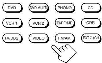
5 Source selecting buttons (20, 21, 23-25, 71-76, 78-80)
DVD, DVD MULTI, PHONO, CD, VCR 1, VCR 2,
TAPE/MD, CDR, TV/DBS,VIDEO, FM/AM, EXT 7.1CH
6 ANALOG/DIGITAL INPUT button (25, 71)
7 SOUND button (39, 50, 56, 59, 71)
TEST button (39, 71)
9 CCCONVERTERbutton(27,71)
THX button (57, 71)
11 SURROUND button (56, 57, 71)
12 EX/ES/7.1 button (55, 71)
13 SLEEP button (28)
14 Operating buttons for audio/video components (72-76, 79, 80)
15 On-screen operation buttons (36, 46, 64)
- SETUP MENU, ADJUST MENU, SET, EXIT, (UP), (DOWN), (LEFT), (RIGHT)
16 TEXT DISPLAY button (64)
DVD MENU button (73, 76)
[18] AUDIO | (ON) button (20-22, 30, 76)
19 AUDIO (STANDBY) button (22, 30, 76)
VCR1/| (STANDBY/ON) button (73, 75, 80)
TV/CATV/DBS / | (STANDBY/ON) button (73-75, 79)
22 · 10 keys for selecting preset channels (34, 71)
10 keys for adjusting sound (39, 56, 71)
10 keys for adjusting DSP effects (50, 59, 71)
10 keys for operating audio/video components (71-80)
23 SURR/DSP OFF button (56, 57, 59, 60, 71)
24 DSP button (59, 71)
25 ANALOG DIRECT button (27, 71)
26 TV operation mode selector (73-75, 79)
DIMMER button (27)
28 VOLUME + / - buttons (20, 21, 24, 31)
29 MUTING button (26, 32)
30 LIGHT button (18)
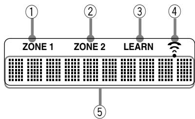
Remote's display window
① ZONE 1 indicator
- Lights up when you press a button on the remote control, with the ZONE 1/ZONE 2 (LEARN/TRANSMIT) selector set to "ZONE 1." This remote control can be used only for Zone 1 operations.
② ZONE 2 indicator
- Lights up when you press a button on the remote control, with the ZONE 1/ZONE 2 (LEARN/TRANSMIT) selector set to "ZONE 2." This remote control can be used only for Zone 2 operations.
③ LEARN indicator
- Lights up when the ZONE 1/ZONE 2 (LEARN/TRANSMIT) selector is set to "LEARN." This remote control cannot operate the receiver or other components, but can memorize IR signals. (See page 78.)
④ Signal transmission indicator
- Lights up when transmitting the remote control signals.
⑤ Remote control operation mode display
- Remote control operation mode such as "DVD," "CD," "SOUND," etc. appears. When the remote control operation mode changes, it is shown on this display for about 10 seconds. (When showing the remote control operation mode just for confirmation, it is shown only for about 5 seconds—e.g. when pressing Number button 1 while the remote control operation mode is "CD," "CD" appears for about 5 seconds.)
This section explains how to connect audio/video components and speakers to the receiver, and how to connect the power supply.
Before Installation
General
- Be sure your hands are dry.
- Turn the power off on all components.
- Read the manuals supplied with the components you are going to connect.
Location
- Install the receiver in a location that is level, well-ventilated and free from moisture.
- The temperature around the receiver must be between -5^ and 35^ (23°F and 95°F).
- Make sure there is good ventilation around the receiver. Poor ventilation could overheat and damage the receiver.
Handling the receiver
- Do not insert any metal object into the receiver.
- Do not disassemble the receiver or remove screws, covers, or cabinet.
- Do not expose the receiver to rain or moisture.
Checking the Supplied Accessories
Check to be sure you have all of the following items, which are supplied for the receiver.
The number in parentheses indicates the quantity of each piece supplied.
- Remote Control (1)
- Batteries (2)
AM Loop Antenna (1)
FM Antenna (1) - RF Rod Antenna (1)
- IR Signal Transmitter (1)
- Double-Sided Adhesive Tape (1)
- Front Terminal Cover (1)
- AC Power Cord (1)
If any item is missing, contact your dealer immediately.
Connecting the FM and AM Antennas
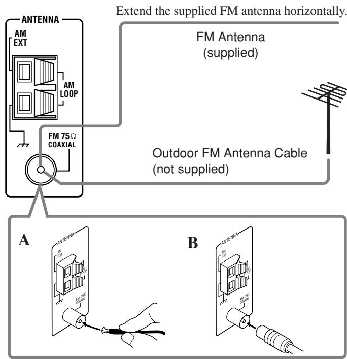
FM Antenna Connections
A. Using the Supplied FM Antenna
The FM antenna provided can be connected to the FM 75 COAXIAL terminal as a temporary measure.
B. Using the Standard Type Connector with an Outdoor FM Antenna (not Supplied)
A standard type connector should be connected to the FM 75 COAXIAL terminal.
Note:
If reception is poor, connect an outdoor antenna.
Before attaching a 75 coaxial cable (the kind with a round wire going to an outdoor antenna), disconnect the supplied FM antenna.
AM Antenna Connections
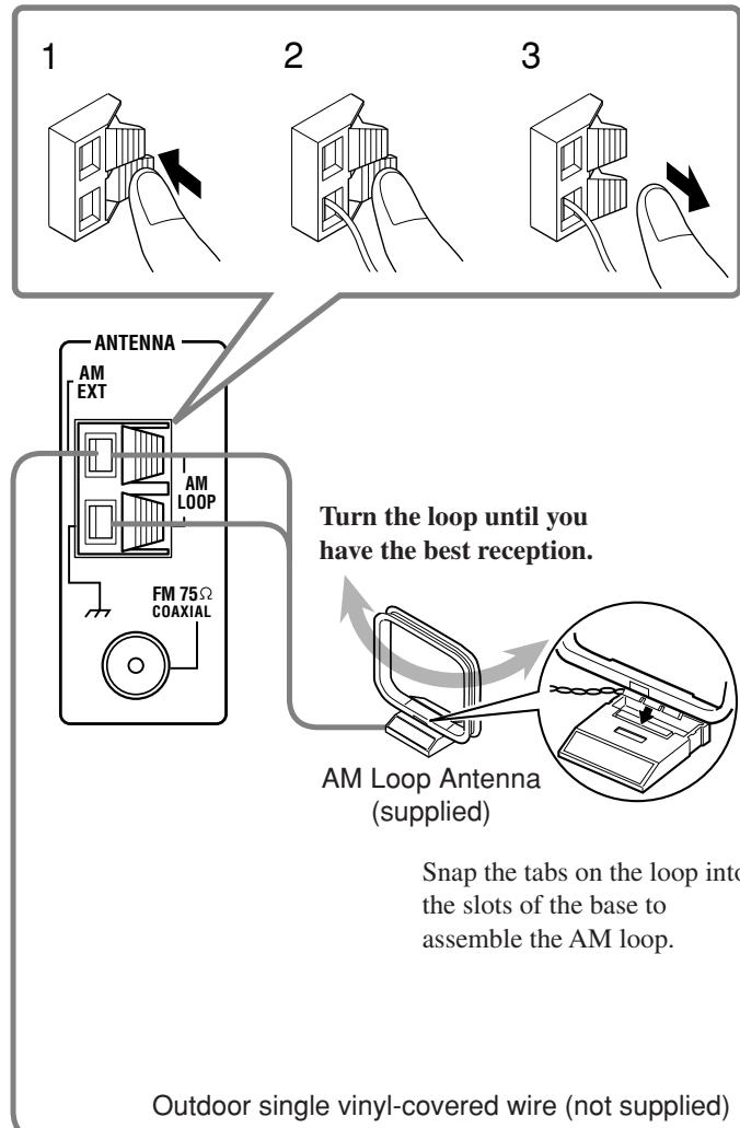
Notes:
- If the AM loop antenna wire is covered with vinyl, remove the vinyl by twisting it as shown in the diagram.
- Make sure the antenna conductors do not touch any other terminals, connecting cords and power cord. This could cause poor reception.
- If reception is poor, connect an outdoor single vinyl-covered wire to the AM EXT terminal. (Keep the AM loop antenna connected.)
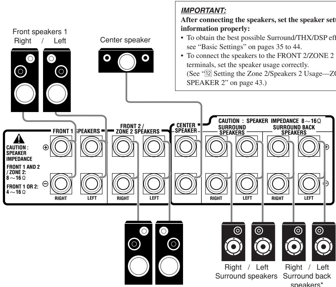
Connecting the Speakers
For full enjoyment of the THX modes (see page 51), it is recommended to use THX-certified speakers. You can connect the following speakers:
- Two pairs of front speakers to produce normal stereo sound.
- One pair of surround speakers to produce a three-dimensional sound movement and environmental background-effect sounds.
- One or one pair of surround back speakers to enjoy 6.1-channel or 7.1-channel sound reproduction. A pair of the speakers is required to use THX Ultra2 Cinema and THX Music modes.
- One center speaker to produce a rich sound image by stabilizing the sound localization (also used to emphasize human voices).
- One powered subwoofer to enhance the bass and to reproduce the LFE channel recorded in multi-channel software.
For each speaker (except for a subwoofer), connect the (+) and (-) terminals on the rear panel to the (+) and (-) terminals marked on the speakers. For connecting a subwoofer, see page 10.
CAUTIONS:
Use only the speakers of the SPEAKER IMPEDANCE indicated by the speaker terminals.
- When connecting to both of the FRONT 1 and FRONT 2 / ZONE 2 SPEAKERS terminals, use speakers with an impedance of 8 to 16 .
- When connecting to either the FRONT 1 or FRONT 2 / ZONE 2 SPEAKERS terminals, use speakers with an impedance of 4 to 16 .
Basic connecting procedure
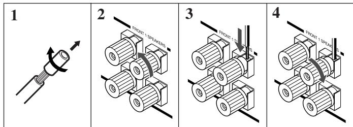
1 Cut, twist, and remove the insulation at the end of each speaker signal cable (not supplied).
2 Turn the knob counterclockwise.
3 Insert the speaker signal cable.
4 Turn the knob clockwise.
Continued on the next page.
Right / Left Front speakers 2
* When using only one surround back speaker, connect it to the LEFT terminals.
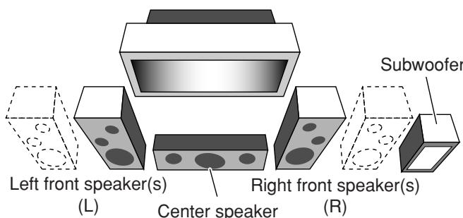
Zone 1 speaker layout
Ideal speaker layout varies depending on the conditions of your listening room. The diagram below is a recommended typical example.
(C)


Right surround speaker (RS)

Surround back speakers (LSB/RSB)
Front speakers and center speaker
- Place these speakers (position of the mid-range speaker units) at the same height from the floor.
- Place these speakers aiming at the listener's ears.
Surround and surround back speakers
- Place these speakers at a position which is 1 meter higher than the listener's ears.
- Point these speakers down aiming at the listener's ears.

Note:
Ideal speaker layout requires that all speakers be placed at the same distance from the listener. However, since in some places it may be difficult to fulfil this requirement, this unit can adjust the delay time so that the sounds through all the speakers reach the listener with the same timing. (See page 40.)
About the FRONT 2/ZONE 2 SPEAKERS terminals
The FRONT 2/ZONE 2 SPEAKERS terminals can be used as follows:
- To connect the second pair of the front speakers in Zone 1.
- To connect the front speakers in Zone 2 when using the multi-room operations (see page 19).
- To connect the front speakers in Zone 1 and to drive them using two amplifiers built in this receiver.
If the speakers connected are of the bi-wiring connection type, you can connect the speakers as illustrated below. (You can use either front speaker terminals for high frequency or for low frequency terminals.)
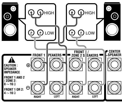
Left Front speaker Rear view Right Front speaker
To use the speaker with the above connection, see “ 12 Setting the Zone 2/Speakers 2 Usage—ZONE 2/SPEAKER 2” on pages 43 and 44.
- When this connection is used, you cannot use the surround back speakers. (In this case, no sounds come out of the SURR BACK PREOUT jacks.)
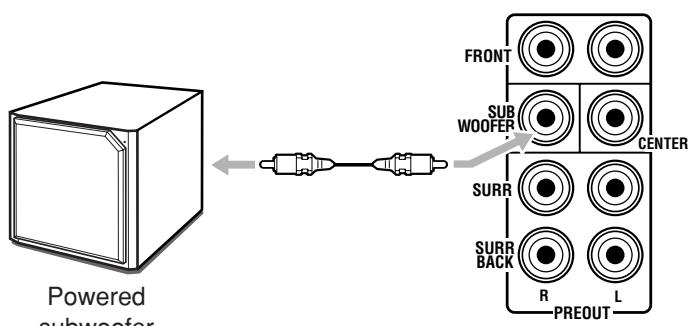
Connecting a subwoofer
You can enhance the bass by connecting a subwoofer.
Connect the input jack of a powered subwoofer to the SUBWOOFER PREOUT jack on the rear panel, using a cable with RCA pin plugs (not supplied).
Enhance your audio system
You can use this receiver as the pre-amplifier (control amplifier) when you connect power amplifiers to the PREOUT jacks on the rear panel, using cables with RCA pin plugs (not supplied).
- Connect the white plug to the audio left jack, and the red plug to the audio right jack.
Left / Right surround back speakers
Connecting Audio/Video Components
When connecting individual components, refer also to the manuals supplied with them.
Analog Connections
Audio component connections
Use the cables with RCA pin plugs (not supplied).
- Connect the white plug to the audio left jack, and the red plug to the audio right jack.
CAUTION:
If you connect a sound-enhancing device such as a graphic equalizer between the source components and this receiver, the sound output through this receiver may be distorted.
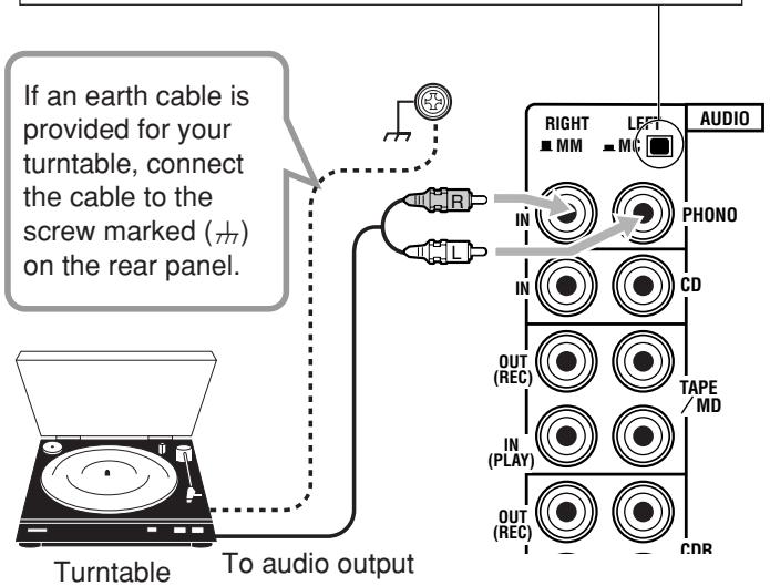
Turntable
Set the MM/MC selector correctly to match it to the turntable connected.
- If an MM (moving-magnet) type cartridge is used by your turntable, push out the selector (MM).
- If an MC (moving-coil) type cartridge is used by your turntable, push in the selector (= MC)
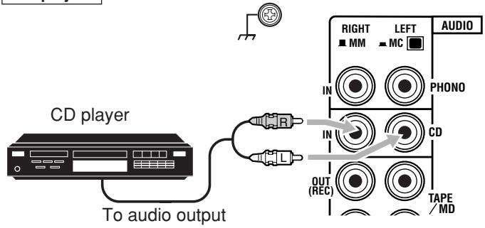
CD player
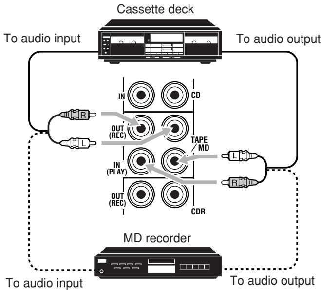
Cassette deck or MD recorder
Note:
You can connect either a cassette deck or an MD recorder to the TAPE/MD jacks. When connecting an MD recorder to the TAPE/MD jacks, change the source name to "MD," which will be shown on the display when selected as the source. See "Changing the Source Name" on page 27 for details.
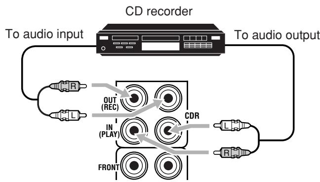
CD recorder
If your audio components have a COMPU LINK or TEXT COMPU LINK jack
- See page 61 for detailed information about the connection and the COMPU LINK remote control system.
- See page 63 for detailed information about the connection and the TEXT COMPU LINK remote control system.
External 7.1-channel output component
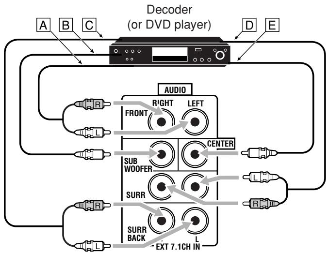
A To left/right front channel output
B To LFE channel (subwoofer) output
C To left/right surround back channel output
D To left/right surround channel output
E To center channel output
Note:
The ZIST circuit (see page 1) is incorporated for the EXT 7.1CH IN jacks to clarify the audio signals independently from the video input circuit. However, if the external component connected to the EXT 7.1CH IN jacks and this receiver are not connected using video cords (composite, S-video, or component), noise may happen to be generated when listening to this external component. In this case, connect the video output jacks on the external component and unused video input jacks on this receiver.
How to view the pictures through an external component connected to the EXT 7.1CH IN (audio input) jacks
The EXT 7.1CH IN jacks do not have any corresponding video input jack on the rear. You have to use one of the following methods to view the pictures through the external component.
- Connect the video output jack on the external component directly to the TV, and select the connected input on the TV.
-
Connect the video output jack on the external component to any one of unused video input jacks on the rear, then...
-
Select that video input as the video source.
- Select "EXT 7.1CH" as the audio source.
(See "Selecting different sources for picture and sound" on page 24).
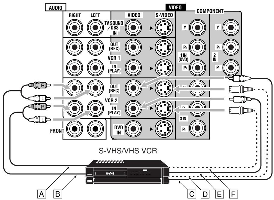
Video component connections
Use cables with RCA pin plugs (not supplied).
Connect the white plug to the audio left jack, the red plug to the audio right jack, and the yellow plug to the video jack.
- If your video components have S-video (Y/C-separation) and/or component video (Y,P_B,P_R) jacks, connect them using an S-video cable (not supplied) and/or component video cable (not supplied). By using these jacks, you can get better picture quality—in the order: Component video > S-video > Composite video.
IMPORTANT:
This receiver is equipped with the following video jacks—composite video, S-video and component video jacks. You can use any of the three to connect a video component
However, observe the following points when make connections:
- Composite video signals and S-video signals can be converted into each other, and can be also converted into component signals. So incoming signals of both types can be emitted through all video output jacks. (If both signals are used, the unit automatically gives priority to S-video signals.)
— Pictures may be distorted if the signals are converted. If this happens, connect the playback source component and TV using the cords of the same type. - When the recording components and this unit are connected using the video cords or S-video cords, playback components and this unit need to be connected using the cords of the same type.
- Component signals cannot be converted. So incoming signals of this type can be emitted only through the component output jacks.
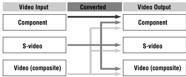
Notice: Pictures through the video components only connected to the component input jacks on the rear of this unit cannot be viewed in Zone 2.
Video camera
The VIDEO input terminals on the front panel are convenient when connecting and disconnecting the component frequently.
- When you do not use the VIDEO input terminals, attach the front terminal cover (supplied) to these jacks to protect them from dust.
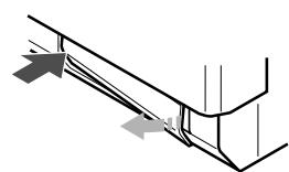
- When attaching the front terminal cover
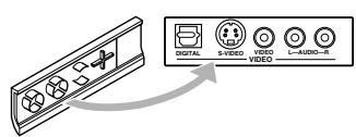
- When removing the cover
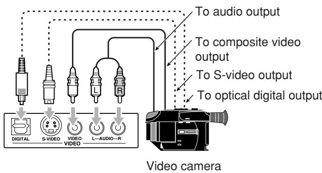
When using the digital input terminal
Select the digital input mode correctly.
For details, see "Selecting the Analog or Digital Input Mode" on page 25.
VCR(s)
A To audio input
To audio output
To component video output
To S-video output
To composite video output
F To S-video input
To composite video input
Notes:
- If the VCR has component video output jacks, you can connect it to either the COMPONENT 1 IN (DVD), 2 IN, or 3 IN jacks. When connecting the VCR to either one of the component input jacks, make the video input terminal setting correctly. For details, see "Setting the Video Input Terminals—VIDEO INPUT" on page 43.
- To view the pictures through the VCR in Zone 2, connect it to either S-video or composite video input jacks.
A To audio output
To audio input
C To composite video input
To S-video input
E To composite video output
F To S-video output
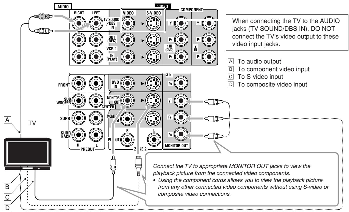
TV and/or DBS tuning
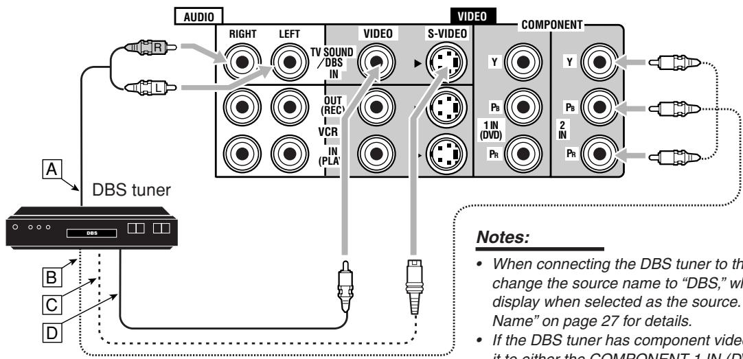
A To audio output
To component video output
To S-video output
To composite video output
Notes:
- When connecting the DBS tuner to the TV SOUND/DBS IN jacks, change the source name to "DBS," which will be shown on the display when selected as the source. See "Changing the Source Name" on page 27 for details.
- If the DBS tuner has component video output jacks, you can connect it to either the COMPONENT 1 IN (DVD), 2 IN, or 3 IN jacks. When connecting the DBS tuner to either one of the component input jacks, make the video input terminal setting correctly. For details, see "Setting the Video Input Terminals—VIDEO INPUT" on page 43.
- To view the pictures through the DBS tuner in Zone 2, connect it to either S-video or composite video input jacks.
A To front left/right channel audio output (or to audiomixed output if necessary)
To composite video output
To S-video output
To component video output
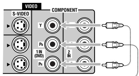
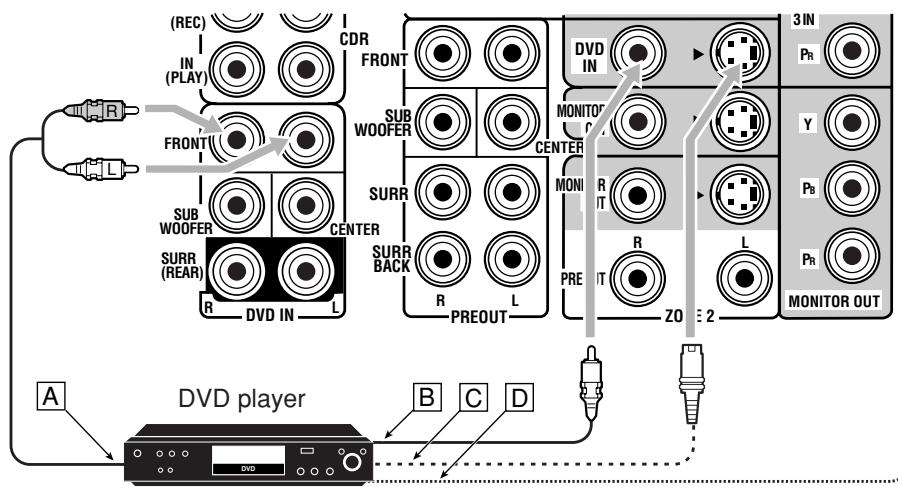
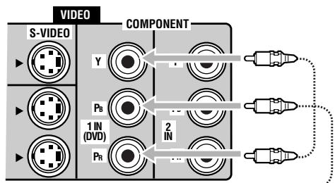
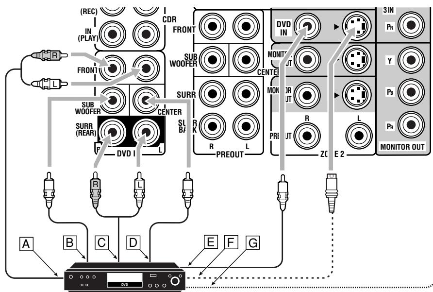
DVD player
- When you connect the DVD player with stereo output jacks:
Notes:
- If the DVD player has component video output jacks, you can connect it to either the COMPONENT 1 IN (DVD), 2 IN, or 3 IN jacks. When connecting the DVD player to either one of the component input jacks, make video input terminal setting correctly. For details, see “[10] Setting the Video Input Terminals—VIDEO INPUT” on page 43.
-
To view the pictures through the DVD player in Zone 2, connect it to either S-video or composite video input jacks.
-
When you connect the DVD player with its analog discrete output (5.1-channel reproduction) jacks:
A To left/right front channel audio output
To subwoofer (LFE) output
To left/right surround channel audio output
To center channel audio output
To composite video output
F To S-video output
To component video output
DVD player
Notes:
- If the DVD player has component video output jacks, you can connect it to either the COMPONENT 1 IN (DVD), 2 IN, or 3 IN jacks. When connecting the DVD player to either one of the component input jacks, make video input terminal setting correctly. For details, see "Setting the Video Input Terminals—VIDEO INPUT" on page 43.
- To view the pictures through the DVD player in Zone 2, connect it to either S-video or composite video input jacks.
Digital Connections
This receiver is equipped with six DIGITAL IN terminals—three digital coaxial terminals and three digital optical terminals—and one DIGITAL OUT (optical) terminal on the rear.
- Another digital optical input terminal is located on the front panel (see page 12).
IMPORTANT:
- When connecting the DVD player, digital TV broadcast tuner, digital VCR, or DBS tuner using the digital terminals, you also need to connect it to the video terminal on the rear. Without connecting it to the video terminal, you cannot view any playback picture.
-
After connecting the components using the DIGITAL IN terminals, set the following correctly if necessary:
-
Set the digital input (DIGITAL IN) terminal setting correctly. For details, see "Setting the Digital Input/Output Terminals—DIGITAL IN/OUT" on page 42.
- Select the digital input mode correctly. For details, see "Selecting the Analog or Digital Input Mode" on page 25.
Digital input terminals
You can connect any digital components having a coaxial or optical digital output terminal.
Digital coaxial cable (not supplied) between digital coaxial terminals
Digital optical cable (not supplied) between digital optical terminals

When the component has a digital coaxial output terminal, connect it to the 1 (DVD), 2 (CD), or 3 (TV/DBS) terminal, using a digital coaxial cable (not supplied).
When the component has a digital optical output terminal, connect it to the 4 (CDR), 5 (MD), or 6 (VCR 1) terminal, using a digital optical cable (not supplied).
Before connecting a digital optical cable, unplug the protective plug.


Notes:
-
When shipped from the factory, the DIGITAL IN terminals have been set for use with the following components:
-
1 (coaxial) : For DVD player
- 2 (coaxial) : For CD player
- 3 (coaxial) : For digital TV broadcast tuner
- 4 (optical) : For CD recorder
-
5 (optical) : For MD recorder
-
6 (optical) : For VCR 1 (VCR connected to the VCR 1 jacks)
-
When you want to operate the CD player, CD recorder, or MD recorder using the COMPU LINK or TEXT COMPU LINK remote control system, connect the target component also as described in "Analog Connections" (see page 11).
- When you want to operate the VCR, TV or DVD player using the AV COMPU LINK remote control system, connect the target component also as described in "Analog Connections" (see pages 13 to 15).
- To use the digital source components for Zone 2, connect them using analog connection methods as well.
Digital output terminal
You can connect any digital component which have an optical digital input terminal.
Digital optical cable (not supplied) between digital optical terminals

When digital recording equipment such as an MD recorder and a CD recorder has a digital optical input terminal, connecting it to the DIGITAL OUT terminal enables you to perform digital-to-digital recording.
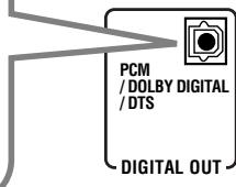
Note:
The format of the digital signals transmitted through the DIGITAL OUT terminal can be determined using the Setup Menu. For details, see "Setting the Digital Input/Output Terminals-DIGITAL IN/OUT" on pages 42 and 43.
Using the RF Rod Antenna and IR Signal Transmitter
The combination of the RF rod antenna and the IR signal transmitter allows you to use the multi-room function more conveniently.
The remote control supplied for this receiver can transmit both RF signal and IR signal at the same time. This receiver catches the RF signals emitted from the remote control, and converts them into IR signals, then transmits the converted signals to the remote sensor on the other components through the IR signal transmitter.
This means that you can control not only this receiver but also other components from Zone 2.
Setting Up the RF Rod Antenna
The remote control supplied for this receiver can transmit both RF (Radio Frequency) signals as well as IR (infrared) signals. The RF rod antenna can receive the RF signals emitted from the remote control. So, with the RF rod antenna connected, you can operate the receiver at a distance of up to 15m (50 feet) using RF signals sent from this receiver (more than twice as far as when using IR signals). Moreover, RF signals can go through walls and other objects in the house so you need not aim at the receiver directly. However, if the antenna cannot receive signals stably, you cannot operate the receiver correctly.
- Without the RF rod antenna connected, you can operate the receiver with the remote control, aiming the remote control directly at the remote sensor on the receiver.
To set up the RF rod antenna
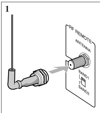
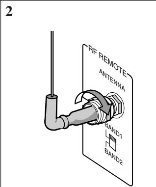
- Insert the RF rod antenna onto the RF REMOTE ANTENNA terminal.
- Rotate the fixing nut to attach the RF rod antenna firmly.
Notes:
- The signal-reachable distance may differ depending on the operating conditions and circumstances. To improve transmitting conditions, change the distance to the receiver and the direction to transmit while operating the remote control.
- To avoid a failure in the reception from the remote control, keep the connecting cables and the IR signal transmitter's cable away from the RF rod antenna.
- If your neighbour uses the same or similar RF remote control system, the receiver may happen to receive the RF signals sent from such an RF remote control system, which could cause your receiver to be operated unintentionally. If this happens, set the BAND 1/2 selectors (both on the rear and on the remote control) to another band (either BAND 1 or BAND 2).
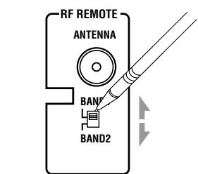
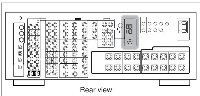
On the main unit's rear
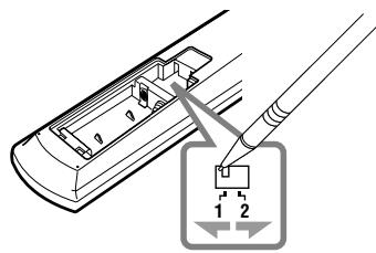
On remote control (Inside the battery compartment)
If the problem still persists, stop using the RF rod antenna and the remote control, and consult your JVC dealer or the nearest JVC Service Center.
Setting Up the IR Signal Transmitter
The IR signal transmitter can retransmit the IR signals. It allows you to use the AV COMPU LINK system, and to operate other manufacturers' components without aiming the remote control directly at the remote sensor on the target components. In addition, the IR signal transmitter reduces the possibility of malfunction.
- The IR signal transmitter may not operate the target components depending on the operating conditions and circumstances—including the aiming angle and direction of the IR signal transmitter at the remote sensors of the target components. If this occurs, changing its aiming angle and direction at the remote sensors may solve the problem.
To set up the IR signal transmitter
1. Find a place where you can attach the IR signal transmitter.
- Place the transmitter where the signal can reach the remote sensor of the target components in a direct line of sight.
- If the cord length of the IR signal transmitter is not long enough, use an extension cord (not supplied).
2. Attach the double-sided adhesive tape (supplied) to the IR signal transmitter.
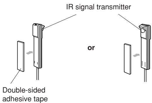
3. Connect the plug of the transmitter to the IR OUT jack of the receiver and attach the transmitter.
Target component(s)
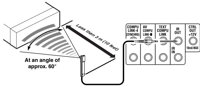
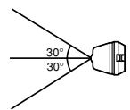
Signal-emitting angle of the transmitter


Connecting the Power Cord
Before plugging the receiver into an AC outlet, make sure that all connections have been made.
Connect one end of the power cord to the AC IN socket on the rear (①) and the other end into an AC outlet (②).
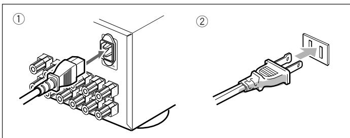
Keep the power cord away from the connecting cables and the antenna. The power cord may cause noise or screen interference.
Note:
The preset settings such as preset channels and sound adjustment may be erased in a few days in the following cases:
- When you unplug the power cord.
- When a power failure occurs.
CAUTIONS:
- Do not touch the power cord with wet hands.
- Do not pull on the power cord to unplug the cord. When unplugging the cord, always grasp the plug so as not to damage the cord.
Putting Batteries in the Remote Control
Before using the remote control, insert the two supplied batteries first.
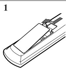
1. On the back of the remote control, remove the battery cover.
2. Insert the batteries.
- Make sure to match the polarity: (+) to (+) and (-) to (-).
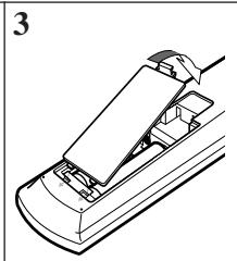
3. Replace the cover.
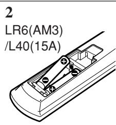
If the remote control cannot transmit signals or operate the receiver correctly, replace the batteries. Use two LR6(AM3)/L40(15A) type (alkaline) dry-cell batteries.
Notes:
- If you aim the remote control directly at the remote sensor on the receiver, you can operate the receiver at a distance of up to 7 m (23 feet).
- When replacing the batteries, finish changing them without delay; otherwise, the stored signals are all erased (see pages 74 to 80).
When using the remote control in the dark
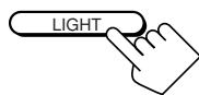
Press LIGHT.
The buttons on the remote control are backlit while you are using the remote control.
If you do not press any button for about 5 seconds, the backlight will turn off.
CAUTIONS:
Follow these precautions to avoid leaking or cracking cells:
- Place batteries in the remote control so they match the polarity: (+) to (+) and (-) to (-).
- Use the correct type of batteries. Batteries that look similar may differ in voltage.
Always replace both batteries at the same time. - Do not expose batteries to heat or flame.
Before operating this receiver any further, be familiar with this multi-room function.
This function enables you to listen to different sources in two different places (we call these two places "Zone 1 [main room]" and "Zone 2 [sub-room]") by using this receiver.
This section explains only the required speaker connections, the concept, and basic operations of the multi-room function. For more detailed operations, see the respective pages in this manual.
Required Connections for Zone 2
- Connect a TV to the ZONE 2 MONITOR OUT jack (either composite video or S-video jack).
- Connect front speakers by using one of the methods described below (either Connection A or Connection B).
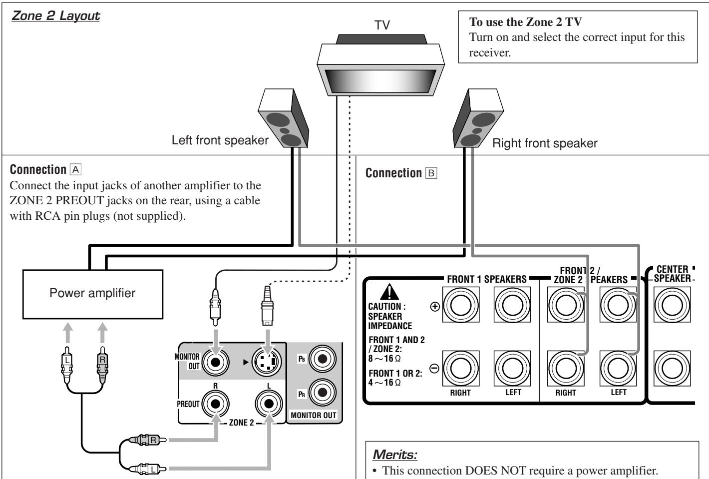
Merits:
- This connection DOES allow you to always use the Surround/THX/DSP mode using the center, surround, and surround back speakers (see pages 51 and 58) and to select "EXT 7.1CH" (see page 60) for the Zone 1 source.
- The output level through the ZONE 2 PREOUT jacks can either be fixed or variable by setting it on the Setup Menu. (See “[12] Setting the Zone 2/Speakers 2 Usage—ZONE 2/SPEAKER 2” on page 43 for more details.)
Demerits:
- This connection DOES require another amplifier.
To use the Zone 2 front speakers
Turn on and operate the other amplifier connected to the ZONE 2 PREOUT jacks correctly.
Note:
Usage of long audio cables/long speaker signal cables will deteriorate the signals and degrade the sound quality.
Merits:
- This connection DOES NOT require a power amplifier.
Demerits:
- When the Zone 2 speakers are activated, this connection DOES NOT allow you to use the Surround/THX/DSP modes using the surround back speakers (see pages 51 and 58) and to select "EXT 7.1CH" (see page 60) for the Zone 1 source.
- When the Surround/THX/DSP modes using the surround back speakers or when "EXT 7.1CH" is selected for Zone 1, this connection DOES NOT allow you to use the Zone 2 speakers.
To use the Zone 2 front speakers connected to the FRONT 2/ ZONE 2 SPEAKERS terminals
See “12 Setting the Zone 2/Speakers 2 Usage—ZONE 2/ SPEAKER 2” on page 43, and “Activating the Zone 2 Front Speakers” on page 32.
Note:
Usage of long speaker signal cables will deteriorate the signals and degrade the sound quality.
Basic Operating Procedure for Zone 1
On the unit:
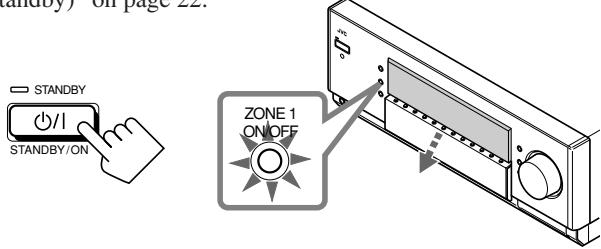
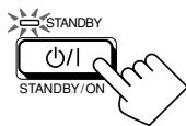
1. Press / (STANDBY/ON).
The STANDBY lamp goes off, and the ZONE 1 ON/OFF lamp lights up.
The front door moves down so that the source selecting buttons appear, and the buttons and controls on the unit work for the Zone 1 operations.
- For more details, see "Turning the Power On and Off (Standby)" on page 22.
The last Zone 1 source is activated.
The last Surround/THX/DSP mode appears.
The volume level appears.
2. Select and play a source.
The sound comes out of the Zone 1 speakers.
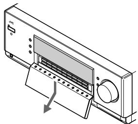
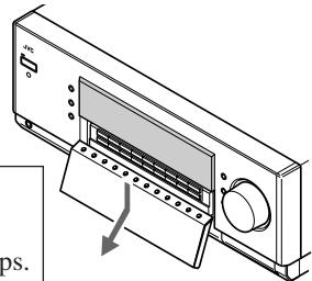
3. Press DOOR DOWN so that you can use the other buttons inside the front door.


To close the front door, press DOOR UP once or twice. The front door moves up in two steps.
4. If no sound comes out of the front speakers, press SPEAKERS 1 and/or SPEAKERS 2 which you want to use.
The selected front speaker indicator(s) light(s) up on the display.
- For more details, see "Activating the Zone 1 Front Speakers" on page 25.
5. Turn MASTER VOLUME to adjust the volume level of the sound through the Zone 1 speakers.
From the remote control:
1. Set ZONE 1/ZONE 2 (LEARN/ TRANSMIT) selector to "ZONE 1."
Now the buttons and controls on the remote control work for the Zone 1 operations.
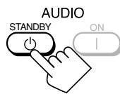
2. Press AUDIO | (ON).
The STANDBY lamp goes off, and the ZONE 1 ON/OFF lamp on the unit lights up. The front door moves down.
- For more details, see "Turning the Power On and Off (Standby)" on page 22.
The last Zone 1 source is activated.
The last Surround/THX/DSP mode appears.
The volume level appears.
3. Select and play a source.

The sound comes out of the Zone 1 front speakers.
- If no sound comes out of the front speakers, press SPEAKERS 1 and/or SPEAKERS 2 on the unit (inside the front door). The selected front speaker indicator(s) light(s) up on the display. For more details, see "Activating the Zone 1 Front Speakers" on page 25.
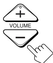
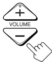
4. Press VOLUME + / - to adjust the volume level of the sound through the Zone 1 speakers.
Basic Operating Procedure for Zone 2
The sources and functions available for the Zone 2 operations are limited.
For more details on the Zone 2 operations, see "Zone 2 (Subroom) Operations" on pages 29 to 32.
On the unit:
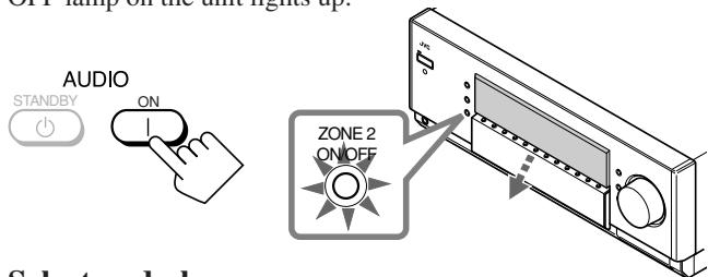
1. Press / (STANDBY/ON).
The STANDBY lamp goes off, and the ZONE 1 ON/OFF lamp lights up.
The front door moves down so that the source selecting buttons appear, and the buttons and controls on the unit work for the Zone 1 operations.
- For more details, see "Turning the Power On and Off (Standby) and Selecting the Zone 2 Operations" on page 29.
2. Press ZONE 2 ON/OFF so that the ZONE 2 ON/OFF lamp lights up.
3. Press DOOR DOWN so that you can use the other buttons inside the front door.

To close the front door, press DOOR UP once or twice.
The front door moves up in two steps.
4. Press ZONE 2 CONTROL so that "ZONE 2" and the previously selected Zone 2 source name appear on the display.
Now the buttons and controls on the unit work for the Zone 2 operations.
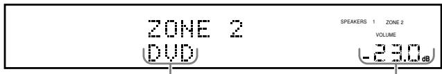
The last Zone 2 source appears.
The Zone 2 volume level appears.
5. Select and play a source.
The sound comes out of the Zone 2 front speakers.
- If no sound comes out of the Zone 2 front speakers, see page 32.
Notes:
- You cannot select "DVD MULTI" and "EXT 7.1CH" for Zone 2.
-
When "TV" has been assigned as the source to the TV/DBS button, it does not work. To change the source name, see "Changing the Source Name" on page 27.
-
Turn MASTER VOLUME to adjust the volume level of the sound through the Zone 2 front speakers.
Note:
When "ZONE2PREOUT" is set to "FIX" on the ZONE 2/ SPEAKERS 2 submenu (see page 43), the MASTER VOLUME control will not work for adjusting the volume level of the sound through the ZONE2 PREOUT jacks.
From the remote control:
When operating the receiver using the remote control, the display on the unit always shows the Zone 1 source information though you are operating it for the Zone 2 source.
1. Set ZONE 1/ZONE 2 (LEARN/ TRANSMIT) selector to “ZONE 2.”
Now the buttons and controls on the remote control work for the Zone 2 operations.
2. Press AUDIO | (ON).
The STANDBY lamp on the unit goes off, and the ZONE 2 ON/OFF lamp on the unit lights up.
3. Select and play a source.
The sound comes out of the Zone 2 front speakers.
- If no sound comes out of the Zone 2 front speakers, see page 32.
Notes:
- You cannot select "DVD MULTI" and "EXT 7.1CH" for Zone 2.
- When "TV" has been assigned as the source to the TV/DBS button, it does not work. To change the source name, see "Changing the Source Name" on page 27.
4. Press VOLUME + / - to adjust the volume level of the sound through the Zone 2 front speakers.
Note:
When "ZONE2PREOUT" is set to "FIX" on the ZONE 2/ SPEAKERS 2 submenu (see page 43), the VOLUME + / - control will not work for adjusting the volume level of the sound through the ZONE2 PREOUT jacks.
Zone 1 (Main Room) Operations
This section explains only the operations commonly used when you play any sound source in Zone 1 (main room). See pages 29 to 32 for the Zone 2 (sub-room) operations.
Before performing Zone 1 operations, it is recommended to finish the basic settings on pages 35 to 44.
IMPORTANT:
Check the following before or while using the buttons and controls.
For Zone 1 operations:
The ZONE 1 ON/OFF lamp on the unit is lit.
- When using the unit:
-ZONE 2" is not shown in the main display.
-Press DOOR DOWN to use the buttons inside the front door.
To close the front door, press DOOR UP.

- When using the remote control:
- Set the ZONE 1/ZONE 2 (LEARN/TRANSMIT) selector to "ZONE 1."
- Check the indication shown on the remote's display when you press a button—this indicates the remote control operation mode together with multi-room operation mode (either ZONE 1 or ZONE 2) for a while.
Ex. When you press FM/AM with ZONE 1/ZONE 2 (LEARN/TRANSMIT) selector set to "ZONE 1."
Turning the Power On and Off (Standby)
On the unit:
To turn on the power, press / (STANDBY/ON).
The STANDBY lamp goes off, and the ZONE 1 ON/OFF lamp lights up. The front door moves down (so that the source selecting buttons appear).

The last Zone 1 source is activated.
The last Surround/THX/DSP mode appears.
The volume level appears.
The currently selected speakers 1 and/or 2 indicator(s) also light(s) up on the display.
- If neither speakers 1 nor 2 indicator is lit on the display, see "Activating the Zone 1 Front Speakers" on page 25.
To turn off the power (into standby mode), press / (STANDBY/ON) again.
The STANDBY lamp lights up, and the front door automatically closes. (The ZONE 1 ON/OFF and/or ZONE 2 ON/OFF lamp goes off.)
- A small amount of power is consumed in standby mode. To turn the power off completely, unplug the AC power cord.
From the remote control:
To turn on the power, press AUDIO | (ON).
The STANDBY lamp goes off, and the ZONE 1 ON/OFF lamp on the unit lights up.
The front door moves down (so that the source selecting buttons appear).
The last Zone 1 source is activated.
The last Surround/THX/DSP mode appears.
The volume level appears.
The currently selected speakers 1 and/or 2 indicator(s) also light(s) up on the display.
- If neither speakers 1 nor 2 indicator is lit on the display, see "Activating the Zone 1 Front Speakers" on page 25.
To turn off the power (into standby mode), press AUDIO 山 (STANDBY).
The STANDBY lamp lights up, and the front door automatically closes. (The ZONE 1 ON/OFF and/or ZONE 2 ON/OFF lamp on the unit goes off.)
Notes:
- Before you turn off the receiver in Zone 1, make sure that no one is listening to any source in Zone 2 (the ZONE 2 ON/OFF lamp is lit on the display) since the Zone 2 sound will also be turned off unexpectedly.
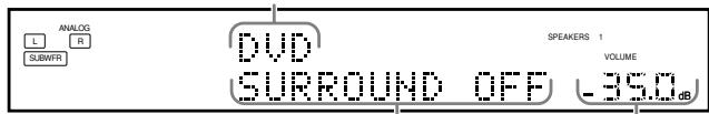
- If you have turned off the receiver with the volume level set at more than level “-35 dB,” the volume level will be automatically set at level “-35 dB” next time you turn on the receiver.
When you turn on the TV connected to the TV SOUND/DBS jacks on the rear
This receiver automatically turns on and selects "TV" as the Zone 1 source about 5 seconds after you turn on the TV. (If you change the source name from "TV" to "DBS," the receiver will not turn on along with the TV. See "Changing the Source Name" on page 27.)
Canceling the Zone 1 Operations
To stop Zone 1 operations and sounds from the Zone 1 speakers, press ZONE 1 ON/OFF so that the ZONE 1 ON/OFF lamp goes off.
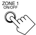
On the unit
From the remote control
The currently selected front speakers indicator(s) also go(es) off from the display (no sound will be heard in Zone 1).
To use this receiver for Zone 1 operations again, press
ZONE 1 ON/OFF again (the ZONE 1 ON/OFF lamp lights up).
The front speakers indicator(s) previously selected light(s) up.
Now the buttons and controls on the unit work for Zone 1 operations.
Notes:
- If you have turned off Zone 1 with the volume level set at more than level “-35 dB,” the volume level will be automatically set at level “-35 dB” next time you turn on Zone 1.
- If "TURN ON ZONE1 OR ZONE2" appears on the display, press ZONE 1 ON/OFF or ZONE 2 ON/OFF to listen to the sound in Zone 1 or in Zone 2; otherwise, the receiver will turn off after about 1 minute.
Selecting the Zone 1 Source to Play
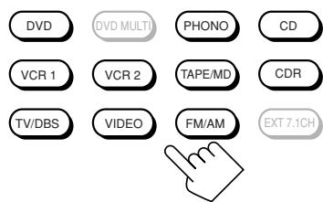
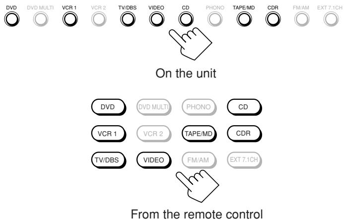
Press one of the source selecting buttons.
- The selected source name and Surround/THX/DSP mode also appear on the display.
On the unit
From the remote control
Selected source name
The current Surround/THX/DSP mode appears.
DVD : Selects the DVD player.
DVD MULTI : Selects the DVD player for viewing a digital video disc using the analog discrete output mode (5.1-channel reproduction). To use the DVD MULTI playback mode, see page 60.
VCR 1 : Selects the video component connected to the VCR 1 IN jacks.
VCR 2 : Selects the video component connected to the VCR 2 IN jacks.
TV/DBS : Selects TV sound (or the DBS tuner).
VIDEO : Selects the video component connected to the VIDEO jacks.
CD^* : Selects the CD player.
PHONO*: Selects the turntable.
TAPE/MD* : Selects the cassette deck (or the MD recorder).
CDR*: Selects the CD recorder.
FM/AM* : Selects the tuner.
Each time you press the button, the band alternates between FM and AM.
EXT 7.1CH : Selects the external component connected to the EXT 7.1CH IN jacks.
To use the EXT 7.1CH playback mode, see page 60.
Notes:
- When connecting an MD recorder (to the TAPE/MD IN jacks), and a DBS tuner (to the TV SOUND/DBS IN jacks), change the source names shown on the display. For details, see "Changing the Source Name" on page 27.
- When you press one of the audio source selecting buttons on the remote control marked with an asterisk (*), the receiver automatically turns on. If you turn on the receiver with the ZONE 1/ZONE 2 (LEARN/TRANSMIT) selector set to “ZONE 2,” press ZONE 1 ON/OFF to activate Zone 1 operations.
- If you press one of the audio source selecting buttons on the remote control with the ZONE 1/ZONE 2 (LEARN/TRANSMIT) selector set to "ZONE 1" while the receiver is turned on but Zone 1 is turned off, Zone 1 is turned on with the audio source selected.
Speaker and signal indicators on the display
By checking the following indicators, you can easily confirm which speakers you are activating and which signals are coming into this receiver.
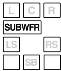
Speaker indicators

Signal indicators
LFE

SB
What speaker indicators light depends on the speaker setting (for details, see “□ Setting the Speakers—SPEAKER SETTING” on page 38).
- The frames of "L," "C," "R," "LS," "RS," and "SB" light up, when the corresponding speakers are set to "LARGE" or "SMALL" and when the speaker is required for the Surround/THX/DSP mode currently selected.
- When "SUBWOOFER" is set to "YES," SUBWFR lights up.
- All three frames on the row of "SB" are not used at the same time. When "SURR BACK OUT" is set to "2SPK," the left and the right ones are used. When it is set to "1SPK," the middle one is used.
The signal indicators light up to show the incoming signals.
L :· When digital input is selected: Lights up when the left channel signal comes in.
- When analog input is selected: Always lights up.
R :· When digital input is selected: Lights up when the right channel signal comes in.
- When analog input is selected: Always lights up.
C : Lights up when the center channel signal comes in.
LFE : Lights up when the LFE channel signal comes in.
LS : Lights up when the left surround channel signal comes in.
RS : Lights up when the right surround channel signal comes in.
S : Lights up when the monaural surround channel signal comes in.
SB : Lights up when the surround back channel signal comes in.
Notes:
- When "DVD MULTI" is selected as the source, "L," "C," "R," "LFE," "LS" and "RS" light up.
- When "EXT 7.1CH" is selected as the source, "L," "C," "R," "LFE," "LS," "RS," and "SB (left/right)" light up. However, "SB" will not light if the THX mode or the DSP mode is activated or if "SPEAKER 2" is set to "BI-AMP OUT" (see page 44).
How to use the speaker and signal indicators
To obtain the best performance of this receiver while using the Surround/THX/DSP modes, check the speaker and signal indicators on the display carefully and set the speakers correctly.
L
C
R
SUBWFR
LFE
LS
RS
SB
Ex. No sound comes out of the center speaker and surround back speakers though center channel and surround back channel signals are coming into this receiver.
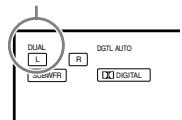
About Dual Mono
Dual Mono can be easily understood when you think of the bilingual broadcast or the MTS (Multi-channel TV Sound) used for some TV programs (however, the Dual Mono format is not identical with those analog formats).
This format is now adopted in Dolby Digital, DTS, and so on. It allows two independent channels (called main channel and sub-channel) to be recorded separately.
- When Dual Mono signals are detected, the
DUAL indicator lights up.
You can select either channel you want to listen to (see page 42).
DUAL indicator
Selecting different sources for picture and sound
While watching pictures from a video source (DVD player, VCR, or DBS tuner), you can listen to sound of an audio source.
- Once you have selected a video source, pictures of the selected source are sent to the TV until you select another video source.
Press one of the audio source selecting buttons—PHONO, CD, TAPE/MD, CDR, FM/AM, EXT 7.1CH—while viewing the picture from a video component such as the VCR or DVD player, etc.
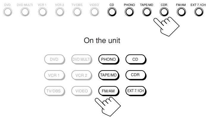
From the remote control
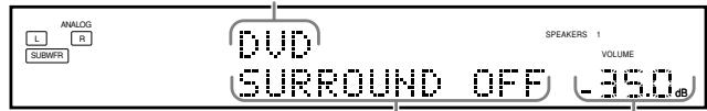
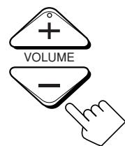
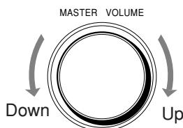
Adjusting the Zone 1 Volume
On the unit:
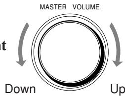
To increase the volume, turn MASTER VOLUME clockwise.
To decrease the volume, turn it counterclockwise.
- When you turn MASTER VOLUME rapidly, the volume level also changes rapidly.
- When you turn MASTER VOLUME slowly, the volume level also changes slowly.
From the remote control:
To increase the volume, press VOLUME+. To decrease the volume, press VOLUME-.
CAUTIONS:
- Always set the volume to the minimum before starting any source. If the volume is set at a high level, the sudden blast of sound energy can permanently damage your hearing and/or ruin your speakers.
- Be careful not to turn up the volume too high when controlling the receiver without listening to the playback sound. For example, when adjusting the volume level in Zone 2 from Zone 1.
Notes:
- The volume level can be adjusted within the range of “-- dB” (minimum), “-71.0 dB” to “+18.0 dB” (maximum).
- If you set One Touch Operation to "ON" (see page 44), you do not have to adjust the volume level each time you change the source. It is automatically set to the stored level. (However, if you have turned off the receiver with the volume level set at more than level "-35 dB," the volume level will be automatically set at level "-35 dB" next time you turn on the receiver.)
Activating the Zone 1 Front Speakers
When shipped from the factory, both pairs of the front speakers have been set to be used in Zone 1.
- To connect the speakers to the FRONT 2/ZONE 2 SPEAKERS terminals, set the speaker usage correctly. (See “12 Setting the Zone 2/Speakers 2 Usage—ZONE 2/SPEAKER 2” on page 43.)
On the unit ONLY:
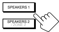
When you have connected two pairs of front speakers and placed them in Zone 1, you can select which to use.
To use the speakers connected to the FRONT 1 SPEAKERS terminals, press SPEAKERS 1 (inside the front door) so that the speakers 1 indicator lights up on the display. (Make sure that the speakers 2 indicator is not lit on the disp
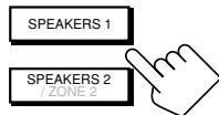
To use the speakers connected to the FRONT 2/ZONE 2 SPEAKERS terminals, press SPEAKERS 2 (inside the front door) so that the speakers 2 indicator lights up on the display. (Make sure that the speakers 1 indicator is not lit on the display.)
To use both sets of the speakers, press SPEAKERS 1 and SPEAKERS 2 so that the speakers 1 and 2 indicators light up on the display.
To use neither set of the speakers, press SPEAKERS 1 and SPEAKERS 2 so that the speakers 1 and 2 indicators disappear from the display.
("HEADPHONE" appears on the unit's display.)
Notes:
-
Even if both pairs of the front speakers are activated, the speakers connected to the FRONT 2/ZONE 2 SPEAKERS terminals are deactivated in the following cases:
-
If you select "DVD MULTI" or "EXT 7.1CH" as the source, or
-
If you select one of the Surround/THX/DSP modes.
-
The SPEAKERS 2 button will not work if "SPEAKER 2" is set to "BI-AMP OUT" (see page 44).
Listening with headphones only:
Sounds through the front speakers and the subwoofer shut off when connecting a pair of headphones to the PHONES jack. ("HEADPHONE" appears on the unit's display.)
You can enjoy the following sound effects through the headphones:
- If the Surround/THX mode is activated, you can enjoy surround effect. (For details, see "3D HEADPHONE Mode" on page 57.)
- If a DSP mode is activated, you can enjoy the DSP effect. (For details, see "HEADPHONE Mode" on page 58.)
CAUTION:
Be sure to turn down the volume before connecting or putting on headphones, as high volume can damage both the headphones and your hearing.
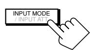
Selecting the Analog or Digital Input Mode
When you have connected digital source components using the digital terminals (see pages 12 and 16), you need to select the digital input mode.
Before you start, remember...
- The digital input (DIGITAL IN) terminal setting should be properly done (see “[9] Setting the Digital Input/Output Terminals—DIGITAL IN/OUT” on page 42).
- The digital input can be used for the Zone 1 sources. The analog input is always selected as the Zone 2 source without respect to this setting.
1. Press one of the source selecting buttons (DVD, VCR 1, TV/DBS, VIDEO, CD, CDR, or TAPE/ MD*) for which you want to change the input mode.
Note:
- If "TAPE" has been assigned to the TAPE/MD button, it does not work in this step. To change the source name, see "Changing the Source Name" on page 27.
2. Press INPUT MODE (or ANALOG/DIGITAL INPUT) to change the input mode.
Each time you press the button, the input mode changes as follows:
On the unit (inside the front door)
ANALOG/DIGITAL
From the remote control
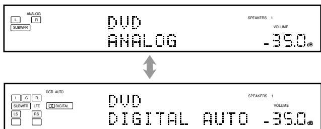
Ex. When the source is "DVD."
| DIGITAL AUTO : Select this for the digital input mode. The receiver automatically detects the incoming signals. The DGTL AUTO indicator lights up on the display, and the digital signal format indicators for the detected signals also light up. |
| ANALOG | : Select this for the analog input mode. The ANALOG indicator lights up. |
When selecting "DIGITAL AUTO," the following indicators indicate the digital signal format of the incoming signal.
LINEARPCM
: Lights up when Linear PCM signals come in.
DIGITAL
: Lights up when Dolby Digital or Dolby Digital EX signals come in.
dt
: Lights up when DTS or DTS-ES signals come in.
No indicator lights up when the receiver cannot recognize the digital signal format of the incoming signals.
When playing software encoded with the Dolby Digital or DTS Surround, the following symptoms may occur:
Sound does not come out at the beginning of playback.
- Noise comes out while searching for or skipping chapters or tracks.
In this case, press RIGHT (or LEFT) on the unit to select "DGTL DOLBY D" or "DGTL DTS" while "DIGITAL AUTO" still remains on the display.
Each time you press the button, the input mode changes as follows:
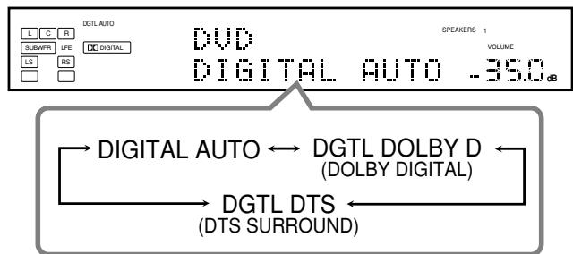
When "DOLBY DIGITAL" or "DTS SURROUND" is selected, the DGTL AUTO indicator goes off, and the corresponding digital signal format indicator (Digital or bits) lights up on the display.
- If the incoming signal does not match the selected digital signal format, the frame of the selected indicator will flash.
Note:
When you turn off the power or select another source, "DOLBY DIGITAL" and "DTS SURROUND" settings are canceled and the digital input mode is automatically reset to "DIGITAL AUTO."
Attenuating the Input Signal
When the input level of the playing source is too high, the sounds will be distorted. If this happens, you need to attenuate the input signal level to prevent sound distortion.
- You have to make this setting for analog each source.
On the unit ONLY:
Press and hold INPUT ATT (inside the front door) so that the INPUT ATT indicator lights up on the display.
Each time you press and hold the button, the input attenuator mode turns on ("INPUT ATT ON") or off ("INPUT ATT OFF").
INPUT ATT indicator
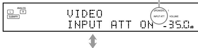
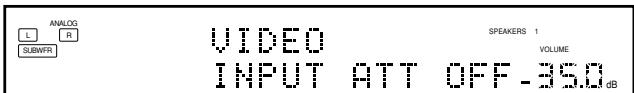
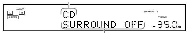
Ex. When the source is "VIDEO."
Notes:
- This effect is applied to only the Zone 1 analog sources.
- This function is not valid when Analog Direct is in use.
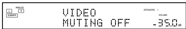
Muting the Zone 1 Sound
From the remote control ONLY:
Press MUTING to mute the sound through all speakers in Zone 1 and headphones connected.
"MITING" appears on the display and the volume turns off (the VOLUME level indicator goes off).
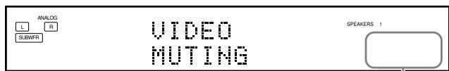
Ex. When the source is "VIDEO." The VOLUME level indicator goes off.
To restore the sound, press MUTING again so that "MUTING OFF" appears on the display for a while.
- Turning MASTER VOLUME on the unit or pressing VOLUME + / - on the remote control also restores the sound.
Changing the Display Brightness
You can dim the display.
Press DIMMER.
Each time you press the button, the brightness level of the display changes as follows:

DIMMER
On the unit
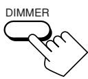
From the remote control

Turning Analog Direct On and Off
You can enjoy the sound quality closer to the original source by skipping the sound adjustments such as Parametric Equalizer (see page 48) and Midnight mode (see page 49). You can only adjust the volume level while Analog Direct is in use.
- You have to make this setting for analog each source.
Press ANALOG DIRECT.
- Each time you press the button, Analog Direct turns on and off.
- When Analog Direct turns on, "ANALOG DIRECT" appears in the main display.
On the unit (inside the front door)

From the remote control
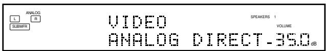
Ex. When the source is "VIDEO."
Notes:
- This function is applied only to the Zone 1 analog sources.
- Activating one of the Surround/THX/DSP modes will cancel Analog Direct automatically.
- If you turn on Analog Direct, the following settings are canceled temporarily—Surround/THX/DSP modes (pages 51 and 58), Input Attenuator (see page 26) and CC Converter, Parametric Equalizer (page 48), and Midnight mode (page 49).
Turning off Analog Direct activates the above settings except the speaker output level settings.
- If you turn off Analog Direct while listening to an analog source, muting time will be a little longer. ( The period during which no sound comes out.)
Making Sounds Natural
JVC's CC (Compensative Compression) Converter eliminates jitter and ripples, achieving a drastic reduction in digital distortion by processing the digital music data in 24 bit quantization and by expanding the sampling frequency to 128kHz (for fs 32kHz / 176.4kHz (for fs 44.1kHz signals)/ 192kHz (for fs 48kHz signals). By using the CC Converter, you can obtain a natural sound field from both digital and analog sources.
Press CC CONVERTER so that the CC CONVERTER lamp lights up.
- Each time you press the button, CC Converter turns on and off (the lamp goes off) alternately.
On the unit
From the remote control
Notes:
- This function is applied only to the Zone 1 sources.
- You cannot use this function while Analog Direct or THX mode is in use. If you turn on Analog Direct or THX mode while this function is in use, this function will be canceled temporarily.
- This function does not work for the surround back channel when the source is "EXT 7.1CH."
- This function is also applied to the output signals through the DIGITAL OUT terminal if the digital signals of fs 48 kHz or less come in (except if the digital signals including surround back signals come in with the surround back speakers activated).
Changing the Source Name
When you have connected an MD recorder to the TAPE/MD IN jacks or the DBS tuner to the TV SOUND/DBS IN jacks on the rear panel, change the source name which will be shown on the display when you select the MD recorder or DBS tuner as the source.
On the unit ONLY:
When changing the source name from "TAPE" to "MD":
- Press TAPE/MD.

- Press and hold TAPE/MD until "ASSGN. MD" appears on the display.
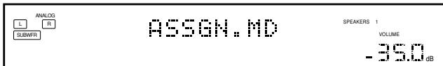
When changing the source name from "TV" to "DBS":
-
Press TV/DBS.
-
Press and hold TV/DBS until "ASSGN. DBS" appears on the display.
To change the source name to "TAPE" or "TV," repeat the same procedure above—press and hold TAPE/MD to select "TAPE," or press and hold TV/DBS to select "TV" in step 2.
- While selecting "DBS" as the Zone 2 source, you cannot change the source name to "TV."
Notes:
- Once you change the source name, it is applied both for the Zone 1 and Zone 2 sources.
-
Without changing the source name, you can still use the connected components. However, there may be some inconvenience:
-
"TAPE" or "TV" will appear on the display when you select the MD recorder or DBS tuner.
-
You cannot use the digital input (see page 25) for the MD recorder.
- You cannot use the COMPU LINK or TEXT COMPU LINK remote control system (see pages 61 and 63) to operate the MD recorder.
Using the Sleep Timer
Using the Sleep Timer, you can fall asleep to music and know the receiver will turn off by itself rather than play all night.
- Sleep Timer works for the Zone 1 source only.
From the remote control ONLY:
Press SLEEP repeatedly.
The SLEEP indicator lights up on the display, and the shut-off time changes as follows (in minutes):

SLEEP indicator
Ex. When the source is "VIDEO."
When the shut-off time comes
The receiver turns off automatically.
- If the Zone 2 source is still playing (the ZONE 2 ON/OFF lamp is lit) when the shut-off time comes, the receiver will not turn off, and only the Zone 1 source will shut off.
To check or change the time remaining until the shut-off time Press SLEEP once.
The remaining time until the shut-off time appears in minutes.
- To change the shut-off time, press SLEEP repeatedly.
To cancel the Sleep Timer
Press SLEEP repeatedly until "SLEEP 0min." appears on the display. (The SLEEP indicator goes off.)
- Turning off the power also cancels the Sleep Timer.
Recording a Source
For analog-to-analog recording
You can record any analog source through the receiver to
- the cassette deck (or MD recorder) connected to the TAPE/ MD OUT jacks,
- the VCRs connected to the VCR 1 OUT and VCR 2 OUT jacks, and
- the CD recorder connected to the CDR OUT jacks — at the same time.
For digital-to-digital recording
You can record the currently selected digital input source through the receiver to a digital recording device connected to the DIGITAL OUT terminal.
Notes:
- Analog-to-digital and digital-to-analog recordings are not possible.
- No sound adjustments can affect the recording.
IMPORTANT:
- While recording, do not turn off the receiver or Zone 1 source; otherwise, recording will stop.
- If the same source is selected both for Zone 1 and Zone 2, operating the Zone 2 source will affect the recording.
Basic adjustment auto memory
This receiver memorizes sound settings for each Zone 1 source
- when you turn on the power,
- when you change the source, and
- when you turn on One Touch Operation (see page 44).
When you change the Zone 1 source, the memorized settings for the newly selected source are automatically recalled.
The following can be stored for each source:
- Analog/digital input mode (see page 25)
- Input Attenuator mode (see page 26)
- Analog Direct (see page 27)
- Parametric Equalizer setting (see page 48)
- Midnight mode (see page 49)
- Surround/THX mode (see page 51)
DSP mode (see page 58)
Notes:
- If the source is FM or AM, you can assign a different setting for each band.
- The memorized settings are not applied when a source is selected for Zone 2.
- If you want to memorize the volume level together with the above settings, set One Touch Operation to "ON" (see page 44).
This section explains only the operations used when you play a sound source in Zone 2.
See pages 22 to 28 for the Zone 1 operations.
Before performing the Zone 2 operations, it is recommended to finish the basic settings on pages 35 to 44.
IMPORTANT:
Check the following before or while using the buttons and controls.
For Zone 2 operations:
The ZONE 2 ON/OFF lamp on the unit is lit.
- When using the unit:
-ZONE 2" is shown in the main display.
- Press DOOR DOWN to use the buttons inside the front door.
To close the front door, press DOOR UP.

- When using the remote control:
When operating the receiver using the remote control, the display on the unit always shows the Zone 1 source information though you are operating it for the Zone 2 source.
- Set the ZONE 1/ZONE 2 (LEARN/TRANSMIT) selector to "ZONE 2."
- Check the indication shown on the remote's display when you press a button—this indicates the remote control operation mode together with multi-room operation mode (either ZONE 1 or ZONE 2) for a while.

Ex. When you press FM/AM with ZONE 1/ZONE 2
(LEARN/TRANSMIT) selector set to "ZONE 2."
To use the Zone 2 TV (connected to the ZONE 2 MONITOR OUT jack)
Turn on the TV and select the correct input for this receiver manually.
For those who connect the Zone 2 front speakers to the ZONE 2 PREOUT jacks through another amplifier (see page 19)
You have to determine how to adjust the volume level through the Zone 2 front speakers. (See "12 Setting the Zone 2/Speakers 2
Usage—ZONE 2/SPEAKER 2" on page 43 for more details.)
To use the Zone 2 front speakers
1 Turn on the other amplifier connected to the ZONE 2 PREOUT jacks.
2 Adjust the volume level through the Zone 2 front speakers either on the other amplifier or on this receiver (depending on the ZONE2PREOUT setting—see page 43).
Turning the Power On and Off (Standby) and Selecting the Zone 2 Operations
On the unit:
- Press / (STANDBY/ON).
The STANDBY lamp goes off, and the ZONE 1 ON/OFF lamp lights up.
The front door moves down so that the source selecting buttons appear.
- The unit is now activated only for Zone 1 operations.
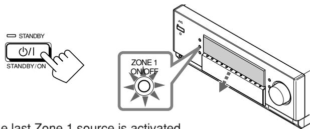
The last Surround/THX/DSP mode appears.
The volume level appears.
The currently selected speakers 1 and/or 2 indicator(s) light(s) up on the display.
-
Press ZONE 2 ON/OFF so that the ZONE 2 ON/OFF lamp lights up.
-
When connecting the Zone 2 front speakers to the FRONT 2/ZONE 2 SPEAKERS
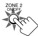
terminals, see also “ 12 Setting the Zone 2/Speakers 2 Usage—ZONE 2/SPEAKER 2” on page 43, and “Activating the Zone 2 Front Speakers” on page 32.
- Press ZONE 2 CONTROL (inside the front door) so that "ZONE 2" and the previously selected Zone 2 source name appear on the display.
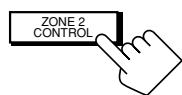
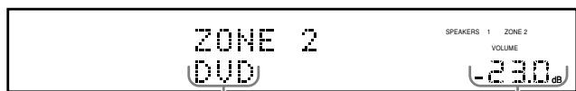
The last Zone 2 source appears.
The Zone 2 volume level appears.
Now the buttons and controls on the unit work for Zone 2 operations.
Each time you press the button, the buttons and controls on the unit are activated or deactivated for Zone 2 operations.
To turn off the power (into standby mode), press / (STANDBY/ON) again.
The STANDBY lamp lights up, and the front door automatically closes. (The ZONE 1 ON/OFF and/or ZONE 2 ON/OFF lamp goes off.)
- A small amount of power is consumed in standby mode. To turn the power off completely, unplug the AC power cord.
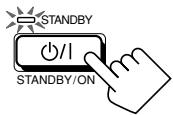
From the remote control:
1. Set ZONE 1/ZONE 2 (LEARN/ TRANSMIT) selector to "ZONE 2."
Now the buttons and controls on the remote control work for Zone 2 operations.
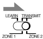
2. Press AUDIO | (ON).
The STANDBY lamp on the unit goes off, and the ZONE 2 ON/OFF lamp on the unit lights up.
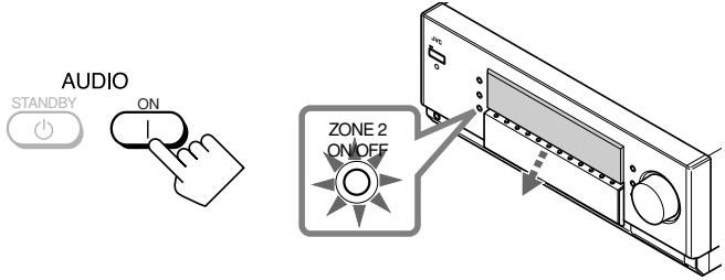
- When connecting the Zone 2 front speakers to the FRONT 2/ZONE 2 SPEAKERS terminal, see also “12 Setting the Zone 2/Speakers 2 Usage—ZONE 2/SPEAKER 2” on page 43, and “Activating the Zone 2 Front Speakers” on page 32.
To turn off the power (into standby mode), press AUDIO (STANDBY).
The STANDBY lamp lights up, and the front door automatically closes. (The ZONE 1 ON/OFF and/or ZONE 2 ON/OFF lamp on the unit goes off.)

Note:
If you have turned off the receiver with the volume level set at more than level “-35 dB,” the volume level will be automatically set at level “-35 dB” next time you turn on the receiver.
Canceling the Zone 2 Operations
On the unit:
To stop Zone 2 operations and sounds through the Zone 2 speakers, press ZONE 2 ON/OFF so that the ZONE 2 ON/OFF lamp goes off.
No sound will be heard in Zone 2, and the display changes to show the Zone 1 source.

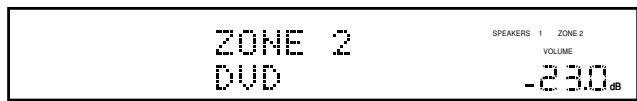
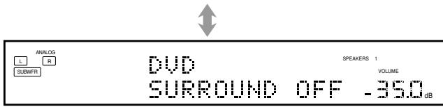
To use this receiver for Zone 2 operations again
- Press ZONE 2 ON/OFF again so that the ZONE 2 ON/OFF lamp lights up.
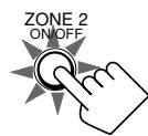
2. Press ZONE 2 CONTROL (inside the front door).
The name of the current source for Zone 2 appears on the display.
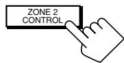
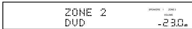
From the remote control:
To stop Zone 2 operations and sounds through the Zone 2 speakers, press ZONE 2 ON/OFF so that the ZONE 2 ON/OFF lamp on the unit goes off.
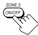
To use this receiver for Zone 2 operations again, press ZONE 2 ON/OFF again.
Notes:
- If you have turned off Zone 2 with the volume level set at more than level “-35 dB,” the volume level will be automatically set at level “-35 dB” next time you turn on Zone 2.
- If "TURNOZONE1 OR ZONE2" appears on the display, press ZONE 1 ON/OFF or ZONE 2 ON/OFF to listen to the sound in Zone 1 or in Zone 2; otherwise, the receiver will turn off after about 1 minute.
Selecting the Zone 2 Source to Play
Press one of the source selecting buttons.
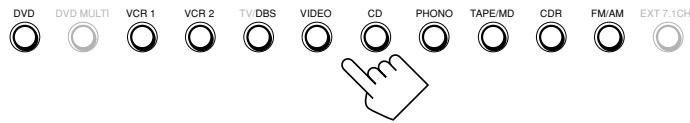
On the unit
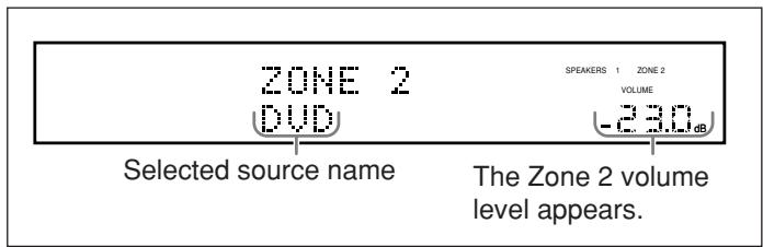
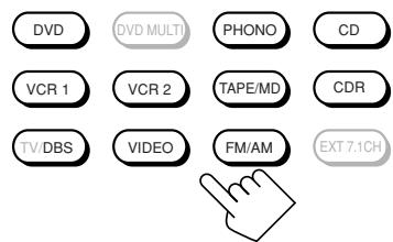
From the remote control
DVD : Selects the DVD player.
VCR 1 : Selects the video component connected to the VCR 1 IN jacks.
VCR 2 : Selects the video component connected to the VCR 2 IN jacks.
TV/DBS : Selects the DBS tuner.
- Does not work for selecting TV.
VIDEO : Selects the video component connected to theVIDEOjacks.
CD^* : Selects the CD player.
PHONO*: Selects the turntable.
TAPE/MD* : Selects the cassette deck (or the MD recorder).
CDR*: Selects the CD recorder.
FM/AM*: Selects the tuner.
Each time you press the button, the band alternates between FM and AM.
Notes:
-
When you press one of the audio source selecting buttons on the remote control marked with an asterisk () , the receiver automatically turns on. If you turn on the receiver with ZONE 1/ ZONE 2 (LEARN/TRANSMIT) selector set to "ZONE 1," press ZONE 2 ON/OFF to activate Zone 2 operations.
-
If you press one of the audio source selecting buttons on the remote control with the ZONE 1/ZONE 2 (LEARN/TRANSMIT) selector set to "ZONE 2" while the receiver is turned on but Zone 2 is turned off, Zone 2 is turned on with the audio source selected.
-
You cannot select the following as a Zone 2 source:
-
"TV," "DVD MULTI," and "EXT 7.1CH"
- Any digital input
You can only select the analog input as the Zone 2 source. (If analog connections have not been made, no sound comes out of the Zone 2 speakers.)
Selecting different sources for picture and sound
While watching pictures from a video source (DVD player, VCR, or DBS tuner), you can listen to sound of an audio source.
- Once you have selected a video source, pictures of the selected source are sent to the TV until you select another video source.
Press one of the audio source selecting buttons—PHONO, CD, TAPE/MD, CDR, FM/AM—while viewing the picture from a video component such as the VCR or DVD player, etc.
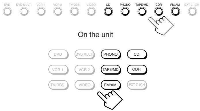
From the remote control
Adjusting the Zone 2 Volume
On the unit:
To increase the volume, turn MASTER VOLUME clockwise.
To decrease the volume, turn it counterclockwise.
- When you turn MASTER VOLUME rapidly, the volume level also changes rapidly.
- When you turn MASTER VOLUME slowly, the volume level also changes slowly.
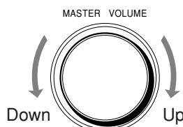
From the remote control:
To increase the volume, press VOLUME ^+ To decrease the volume, press VOLUME -
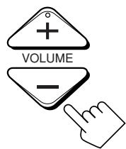
CAUTIONS:
- Always set the volume to the minimum before starting any source. If the volume is set at a high level, the sudden blast of sound energy can permanently damage your hearing and/or ruin your speakers.
- Be careful not to turn up the volume too high when controlling the receiver without listening to the playback sound. For example, when adjusting the volume level in Zone 2 from Zone 1.
Notes:
- The volume level can be adjusted within the range of “-- dB” (minimum) “-71.0 dB” to “+18.0 dB” (maximum).
- With "ZONE2PREOUT" set to "VARIABLE" (see page 43), no sounds come out of the ZONE 2 PREOUT jacks if the volume level is set to "---dB." In this case, increasing the volume level will enable the sound output through the ZONE 2 PREOUT jacks.
Activating the Zone 2 Front Speakers
This section is NOT applicable to those who connect the Zone 2 front speakers through the ZONE 2 PREOUT jacks through another amplifier (see page 19).
Before you start, remember...
- When shipped from the factory, both pairs of the front speakers have been set to be used in Zone 1. To use the speakers connected to the FRONT 2/ZONE 2 SPEAKERS terminals, set the speaker usage correctly. (See “ 12 Setting the Zone 2/Speakers 2 Usage—ZONE 2/SPEAKER 2” on page 43.)
On the unit ONLY:
Press ZONE 2 to activate the Zone 2 front speakers.
The ZONE 2 speaker indicator lights up on the display.
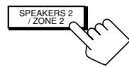
ZONE 2 speaker indicator
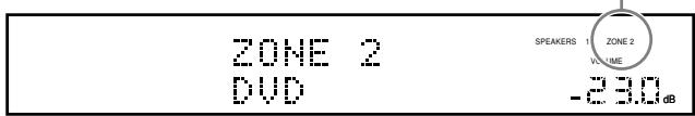
To deactivate the Zone 2 front speakers, press ZONE 2 again. The ZONE 2 speaker indicator goes off.
Notes:
- The ZONE 2 button does not work:
- If "SPEAKER 2" is set to "BI-AMP OUT" (see page 44), or
- If you are using 7.1-channel reproduction (including "EXT 7.1 CH") in Zone 1.
- While the Zone 2 front speakers are activated, you cannot use the surround back speakers for the Surround/THX/DSP modes in Zone 1.
For those who connect the Zone 2 front speakers using the ZONE 2 PREOUT jacks through another amplifier (see page 19)
You have to determine how to adjust the volume level through the Zone 2 front speakers. (See “[12] Setting the Zone 2/Speakers 2 Usage—ZONE 2/SPEAKER 2” on page 43 for more details.)
To use the Zone 2 front speakers
1 Turn on the other amplifier connected to the ZONE 2 PREOUT jacks.
2 Adjust the volume level of Zone 2 front speakers either on the other amplifier or on this receiver (depending on the ZONE2PREOUT setting—see page 43).
Muting the Zone 2 Sound
From the remote control ONLY:
Press MUTING to mute the sound through the Zone 2 front speakers.
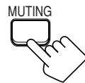
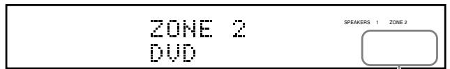
The VOLUME level indicator goes off.
To restore the sound, press MUTING again so that the VOLUME level indicator appears on the display.
- Turning MASTER VOLUME on the unit or pressing VOLUME +/- on the remote control also restores the sound.
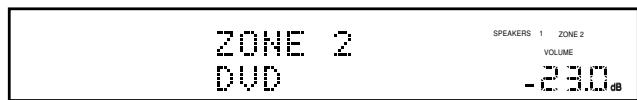
Note:
Sounds through the Zone 2 front speakers connected to the ZONE 2 PREOUT jacks through another amplifier are also muted when "ZONE2PREOUT" is set to "VARIABLE" (see page 43).
- When “ZONE2PREOUT” is set to “FIX,” the MUTING button does not work. In this case, mute the sounds on the connected amplifier.
You can browse through all the stations or use the preset function to go immediately to a particular station.

Indicates the functions YOU CAN ALSO USE when the receiver is ready for Zone 2 operations.
IMPORTANT:
Check the following before or while using the buttons and controls.
For Zone 1 operations:
The ZONE 1 ON/OFF lamp on the unit is lit.
For Zone 2 operations:
The ZONE 2 ON/OFF lamp on the unit is lit.
- When using the unit:
-For the Zone 1 operations: "ZONE 2" is not shown in the main display.
-For the Zone 2 operations: "ZONE 2" is shown in the main display.
-Press DOOR DOWN to use the buttons inside the front door. To close the front door, press DOOR UP.


- When using the remote control:
When operating the receiver using the remote control, the display on the unit always shows the Zone 1 source information though you are operating it for the Zone 2 source.
- Set the ZONE 1/ZONE 2 (LEARN/TRANSMIT) selector to “ZONE 1” or “ZONE 2” correctly.
- Check the indication shown on the remote's display when you press a button—this indicates the remote control operation mode together with multi-room operation mode (either ZONE 1 or ZONE 2) for a while.
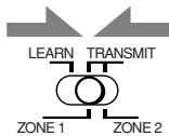
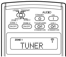
Ex. When you press FM/AM with ZONE 1/ZONE 2 (LEARN/TRANSMIT) selector set to "ZONE 1.
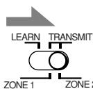
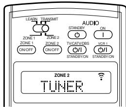
Ex. When you press FM/AM with ZONE 1/ZONE 2 (LEARN/TRANSMIT) selector set to "ZONE 2."
Tuning in to Stations Manually

1. Press FM/AM.
The last received station of the last selected band is tuned in.
Each time you press the button, the band alternates between FM and AM.

On the unit (inside the front door)

From the remote control
When operating for Zone 1

When operating for Zone 2
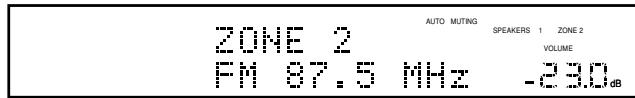
2. Press TUNING / (inside the front door) or TUNING UP/DOWN until you find the frequency you want.
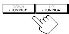
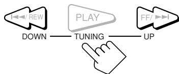
On the unit (inside the front door)
From the remote control
Notes:
- When a station of sufficient signal strength is tuned in, the TUNED indicator lights up on the display.
- When an FM stereo program is received, the STEREO indicator also lights up.
- When you hold the button (and release it) in step 2, the frequency keeps changing until a station is tuned in.
- You can only select the same station of the same band (FM or AM) for both Zone 1 and Zone 2 operations. If you change the station for Zone 2, it also changes for Zone 1 (and vice versa: indications in the main display also change). This also means that if you change the station for Zone 2 while recording a broadcasting program in Zone 1, recording in Zone 1 will be interrupted.
Using Preset Tuning
Once a station is assigned to a channel number, the station can be quickly tuned in. You can preset up to 30 FM and 15 AM stations.
To store the preset stations
Before you start, remember...
- There is a time limit in doing the following steps. If the setting is canceled before you finish, start from step 1 again.
On the unit ONLY:
1. Tune in to an FM or AM station you want to preset (see "Tuning in to Stations Manually" on page 33).
- If you want to store the FM reception mode for an FM station, select the FM reception mode you want. See "Selecting the FM Reception Mode."
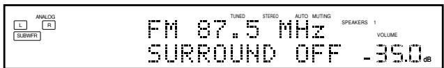
2. Press MEMORY (inside the front door).
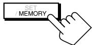
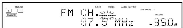
The channel number position starts flashing on the display for about 10 seconds.
3. Press PRESET / (inside the front door) to select a channel number while the channel numb position is flashing.
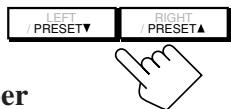
4. Press MEMORY again while the selected channel number is flashing on the display.
The selected channel number stops flashing.
The station is assigned to the selected channel number.
5. Repeat steps 1 to 4 until you store all the FM and AM stations you want.
To erase a stored preset station
Storing a new station on a used number erases the previously stored one.
To tune in to a preset station

On the unit:
1. Press FM/AM.
The last received station of the last selected band is tuned in.
Each time you press the button, the band alternates between FM and AM.
2. Press PRESET / (inside the front door) until you find the channel you want.

From the remote control:
1. Press FM/AM.
The last received station of the last selected band is tuned in.
Each time you press the button, the band alternates between FM and AM.
2. Press the 10 keys to select a preset channel number.
- For channel number 5, press 5.
- For channel number 15, press +10 then 5.
- For channel number 20, press +10 then 10.
- For channel number 30, press +10 , +10 , then 10.
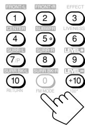
Note:
You can only select the same station of the same band (FM or AM) for both Zone 1 and Zone 2 operations. If you change the station for Zone 2, it also changes for Zone 1 (and vice versa: indications in the main display also change). This also means that if you change the station for Zone 2 while recording a broadcasting program in Zone 1, recording in Zone 1 will be interrupted.
Selecting the FM Reception Mode
When an FM stereo broadcast is hard to receive or noisy
You can change the FM reception mode while receiving an FM broadcast.
- You can store the FM reception mode for each preset station.
Press FM MODE.
Each time you press the button, the FM reception mode alternates between "AUTO MUTING" and "MONO."
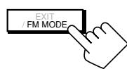
On the unit (inside the front door)
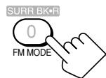
From the remote control
AUTO MUTING: When a program is broadcasted in stereo, you will hear stereo sound; when in monaural, you will hear monaural sounds. This mode is also useful to suppress static noise between stations. The AUTO MUTING indicator lights up on the display.
MONO: Reception will be improved although you will lose the stereo effect. In this mode, you will hear noise while tuning in to the stations. The AUTO MUTING and STEREO indicators go off.
Note:
When you press FM MODE on the remote control, be sure that "TUNER" appears on the remote's display. If not, press FM/AM first to select the FM band, then press FM MODE.
Some of the following settings are required after connecting and positioning your speakers, while others will make operations easier.
Basic setting operations are only possible while the receiver is ready for Zone 1 operations.
Setup Menu Configuration
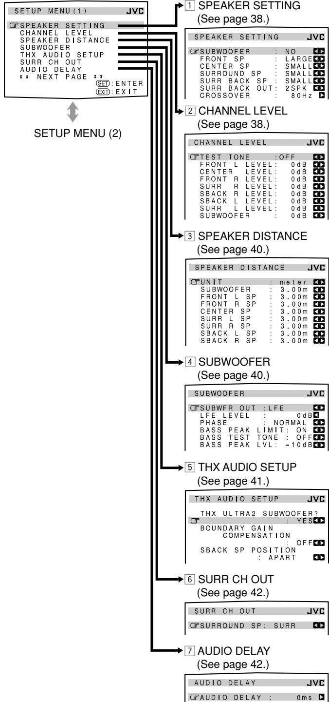
SETUP MENU (1)
Note:
When performing the basic settings viewing the indications on the main unit's display, the indications are slightly different from what are shown on the on-screen display.
This is because of the limited number of characters shown on the main unit's display.
Ex. • "SPEAKER SETTING" is shown as "SP SETTING" on the main unit's display.
- "SPEAKER DISTANCE" is shown as "SP DISTANCE" on the main unit's display.
SETUP MENU (2)
NOTICE—
-
Items on the menus shown above are all set to the initial values when shipped from the factory.
-
However, the SPEAKER DISTANCE, SUBWOOFER, and THX AUDIO SETUP submenu settings are not the initial ones. They are the settings when "SUBWOOFER" is set to "YES" on the SPEAKER SETTING submenu.
-
Some of the menus or some items on the menu cannot be shown or cannot be adjusted. (For details, see the respective explanations in this section.)
IMPORTANT:
Check the following before or while using the buttons and controls.
For Zone 1 operations:
The ZONE 1 ON/OFF lamp on the unit is lit.
- When using the unit:
"ZONE 2" is not shown in the main display.
-Press DOOR DOWN to use the buttons inside the front door.
To close the front door, press DOOR UP.
- When using the remote control:
- Set the ZONE 1/ZONE 2 (LEARN/TRANSMIT) selector to “ZONE 1.”
- Check the indication shown on the remote's display when you press a button—this indicates the remote control operation mode together with multi-room operation mode (either ZONE 1 or ZONE 2) for a while.
Ex. When you press SETUP MENU with ZONE 1/ZONE 2 (LEARN/TRANSMIT) selector set to "ZONE 1."
The buttons for operating the menus are shown on the screen. You can operate the menu with these buttons.
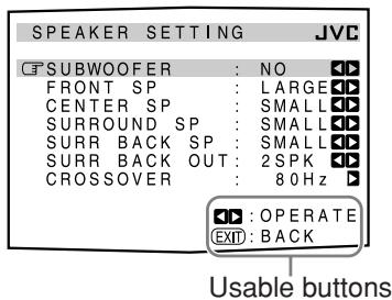
Operation through On-Screen Display Menus
To do the basic settings for this receiver, you can utilize the on-screen display menus in order to finish important settings easily while viewing these menus.
Menu operation buttons
- When no operation is done for about 1 minute, the on-screen menu (as well as the indications in the unit's main display) will disappear.
On the unit:

| Button | To do |
| SETUP MENU | display or erase the Setup Menu. |
| DOWN/UP | select a submenu on the Setup Menu or an item on a submenu (downwards or upwards). |
| SET | move to the selected submenu screen. |
| LEFT/RIGHT | select the desired setting on a submenu. |
| EXIT | exit from menu operations or return to the previous menu. |
From the remote control:
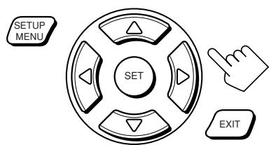
| Button | To do |
| SETUP MENU | display or erase the Setup Menu. |
| ∇ / ∅ | select a submenu on the Setup Menu or an item on a submenu (downwards or upwards). |
| SET | move to the selected submenu screen. |
| < / > | select the desired setting on a submenu. |
| EXIT | exit from menu operations or return to the previous menu. |
Menu Operating Procedure
Ex. When setting the speaker distance
Operations
1. Press SETUP MENU.
On the TV screen
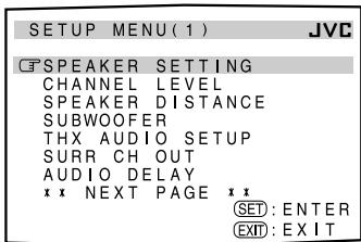
On the main unit's display

The submenu names previously selected appears.
SETUP MENU (1) appears.
2. Press or (DOWN or UP) repeatedly to select the desired submenu.
- In this example, select "SPEAKER DISTANCE" submenu.
Move to "SPEAKER DISTANCE."
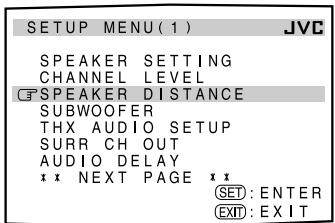
Press the button until "SP (speaker) DISTANCE" appears.
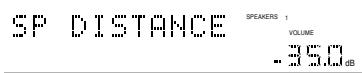
3. Press SET.
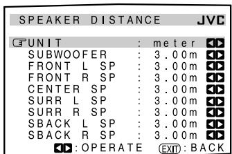
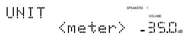
The first item on the selected submenu appears (with the current setting shown on the lower line of the main display).
The selected submenu appears.
4. Set a desired item on the submenu.
① Press or (DOWN or UP) repeatedly to select an item.
(2) Press or (RIGHT or LEFT) to set the item.
- In this example, set "UNIT" to "feet" for indicating the speaker distance.
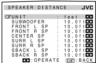
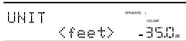
5. Set other items on the same submenu if necessary.
① Press or (DOWN or UP) repeatedly to select another item on the same submenu.
(2) Press or (RIGHT or LEFT) to set the item.
- In this example, set the center speaker distance.
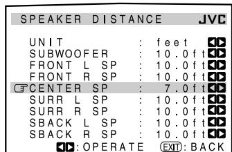
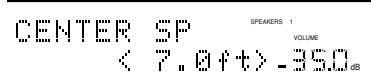
To move between the SETUP MENU (1) and (2)
- By simply pressing (or DOWN) repeatedly on the SETUP MENU (1), you can go to the SETUP MENU (2).
- By simply pressing (or UP) repeatedly on the SETUP MENU (2), you can go back to the SETUP MENU (1).
To return to the previous screens
Press EXIT.
Each time you press the button, the on-screen display menu returns to the one previously displayed. (On the main unit's display, the indications also change accordingly.)
To erase the menu (to return to the regular screen)
Press SETUP MENU.
Setting the Speakers—SPEAKER SETTING

To obtain the best possible surround sound of the Surround/THX/DSP modes in Zone 1, you have to register the information about the speaker arrangement after all connections are completed.
SUBWOOFER
Register whether you have connected a subwoofer.
YES : Select when a subwoofer is connected.
NO : Select when no subwoofer is used.
FRONT SP, CENTER SP, SURROUND SP, SURR BACK SP
Register the speaker size for each speaker connected—front speakers, center speaker, surround speakers, and surround back speakers.
LARGE : Select when the speaker size is relatively large.
SMALL : Select when the speaker size is relatively small.
NONE : Select when you have not connected a speaker. (Not selectable for the front speakers)
Notes:
- Keep the following comment in mind as reference when adjusting:
- If the size of the cone speaker unit built in your speaker is greater than 12 cm (4 3/4 inches), select "LARGE," and if it is smaller than 12 cm (4 3/4 inches), select "SMALL."
- If you have selected "NO" for the subwoofer, you can only select "LARGE" for the front speakers.
- If you have selected "SMALL" for the front speakers, you cannot select "LARGE" for the center, surround, and surround back speakers.
- If you have selected "SMALL" for the surround speakers, you cannot select "LARGE" for the surround back speakers.
- If you have selected "NONE" for the surround speakers, the surround back speakers are fixed to "NONE."
SURR BACK OUT
Register the number of the surround back speakers connected you can use only one unit or a pair of the units for your surround back sounds.
1SPK : Select when only one speaker is connected for your surround back sounds—minimum requirement for THX Surround EX (see page 51).
2SPK : Select when a pair of speakers are connected for your surround back sounds—requirement for THX Ultra2 Cinema and THX Music (see page 51).
CROSSOVER
You can select the crossover frequency for the small speakers used. The signals below the preset frequency level will be sent to and be reproduced by the subwoofer (or by "LARGE" speakers when "SUBWOOFER" is set to "NO").
Select one of the crossover frequency levels according to the size of the small speaker connected:
80Hz : Select when the cone speaker unit built in the speaker system is about 12 cm (4 3/4 inches).
- When using the THX Certified speakers, the crossover frequency should be set to "80 Hz."
100Hz : Select when the cone speaker unit built in the speaker system is about 10cm (3^15 / 16 inches).
120Hz : Select when the cone speaker unit built in the speaker system is about 8cm (3^3 / 16 inches).
Notes:
- Use the above comments as reference when adjusting. If you have selected "LARGE" for all activated speakers, this function will be set to "OFF."
- Crossover frequency is not valid for "3D HEADPHONE."
- If Analog Direct is in use, this function does not take effect.
Adjusting the Speaker Channel Output Levels—CHANNEL LEVEL
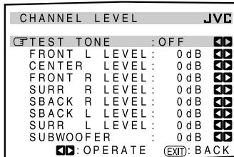
On this submenu, you can adjust the speaker channel output levels. While transmitting the test tone, select a speaker channel and adjust its output level.
Note:
You can show this submenu simply by pressing TEST (after pressing SOUND) on the remote control. The test tone comes out of the activated speakers in sequence.
■ Adjustment procedure on this submenu
Adjustment is also possible without emitting the test tone. In this case, you can skip steps 1, 2, and 6 below.
- You can only adjust the activated speakers on the SPEAKER SETTING submenu (see the left column). The test tone will not come out of the deactivated speakers.
1 Press or (DOWN or UP) to select "TEST TONE."
2 Press or (RIGHT or LEFT) to output the test tone. (See "TEST TONE" on the next page.)
3 Press or (DOWN or UP) to select a speaker you want to adjust.
4 Press or (RIGHT or LEFT) to adjust the speaker output level.
5 Repeat steps 3 and 4 to adjust the other speaker output levels.
6 After adjustment is finished, stop the test tone.
① Press (UP) to select "TEST TONE."
② Press or (RIGHT or LEFT) to select "OFF."
TEST TONE
You can emit the test tone to adjust the speaker output level.
CAUTION:
The test tone is automatically fixed to 0 dB, but this level will be louder than you would expect.
Select one of the following.
- The test tone will be heard for about three seconds after you select "AUTO" or "MANUAL."
AUTO : When this is selected, the test tone comes out of all the activated speakers in the following sequence:
Left front speaker Center speaker Right front speaker
Right surround speaker Right surround back speaker
Left surround back speaker Left surround speaker
Subwoofer (Back to the beginning)
MANUAL: When this is selected, the test tone comes out of only the speaker you select.
OFF : Select this to stop the test tone.
Notes:
- Test tone is not available in the following cases:
- When the Zone 2 front speakers are activated with "SURR BACK SP" is set to either "SMALL" or "LARGE" on the SPEAKER SETTING submenu.
- When a pair of headphones is connected to the PHONES jack.
- If "NO" or "NONE" is selected for a speaker on the SPEAKER SETTING submenu (see page 38), test tone does not come out of the speaker.
Adjusting the speaker channel output levels
To accurately set the output levels, it is recommended to use a handheld sound pressure level (SPL) meter (not supplied). Set the meter to C-weighting and slow averaging. Use the MANUAL test tone option and set each channel so that you read a 75 decibel sound pressure level at the listening point.
Select and adjust the following speaker output levels within the range of -10 dB to +10 dB.
FRONT L LEVEL : Select to adjust the left front speaker output level.
FRONT R LEVEL : Select to adjust the right front speaker output level.
CENTER LEVEL : Select to adjust the center speaker output level.
SURRL LEVEL : Select to adjust the left surround speaker output level.
SURR R LEVEL : Select to adjust the right surround speaker output level.
SBACK L LEVEL*: Select to adjust the left surround back speaker output level.
SBACK R LEVEL*: Select to adjust the right surround back speaker output level.
SUBWOOFER : Select to adjust the subwoofer output level.
Note:
- When "SURR BACK OUT" is set to "1SPK" on the SPEAKER SETTING submenu, "SBACK LEVEL" will appear instead of these two level settings.
To adjust the sound output levels using the 10 keys
You can also use the 10 keys on the remote control to adjust the sound output levels. Once you adjust the sound output levels using the following procedure, the adjustments you have done on the Setup menu will be also changed.
- If you do not emit the test tone, the adjustments you make will be applied temporarily to the current Surround/THX/DSP mode, but cannot be stored in memory.
From the remote control ONLY:
1. Press SOUND.
The 10 keys are activated for sound adjustments.
2. Press TEST once to check the speaker output balance.
The test tone comes out of all the activated speakers in sequence.
- The CHANNEL LEVEL menu (see page 38) appears on the TV screen.
3. Select the speaker you want to adjust.
The selected speaker name appears on the remote's display for a while.
To select the left front speaker, press FRONT · L.
To select the center speaker, press CENTER.
To select the right front speaker, press FRONT·R.
- To select the right surround speaker, press SURR•R.
To select the right surround back speaker, press SURR BK · R.
To select the left surround back speaker, press SURR BK · L.
- To select the left surround speaker, press SURR · L.
- To select the subwoofer, press SUBWFR.
4. Press LEVEL + / - to adjust the speaker output levels.
The speaker name selected in the above step and its level appear on the unit's display.
- You can adjust the levels within the range of -10 dB to +10 dB.
5. Repeat steps 3 and 4 to adjust the other speaker output levels.
- Press TEST again to stop the test tone.
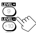
Note:
When Analog Direct is in use, you cannot adjust the speaker output levels without emitting the test tone.

3 Setting the Speaker Distance SPEAKER DISTANCE
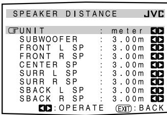
The distance from your listening point to the speakers is another important element to obtain the best possible surround sound of the Surround/THX/DSP modes. You need to set the distance from your listening point to the speakers.
By referring to the speaker distance setting, this unit automatically sets the delay time of the sound through each speaker so that sounds through all the speakers can reach you with the same timing.
UNIT
Select one of the following as your measuring unit:
meter : Select to set the distance by meter.
feet : Select to set the distance by feet.
For each speaker
Set the distance from the listening point within the range of 0.30m (1.0 ft) to 9.00m (30.0 ft), in 0.15m (0.5 ft) intervals.
Notes:
- You cannot set the speaker distance for the speaker you have selected "NO" or "NONE" for on the SPEAKER SETTING submenu.
- This function does not take effect for the surround back channel when the source is "EXT 7.1CH" (with Analog Direct turned off).
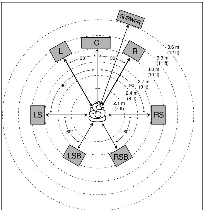
EX. In the above case, set the speaker distance as follows:
Subwoofer (SUBWFR) SUBWOOFER: 3.60m (12.0 ft)
Left front (L) FRONT L SP: 3.00 m (10.0 ft)
Right front (R) FRONT R SP: 3.00 m (10.0 ft)
Center (C) CENTER SP: 3.00 m (10.0 ft)
Left surround (LS) SURLSP: 2.70 m (9.0 ft)
Right surround (RS) SURR R SP: 2.70 m (9.0 ft)
Left surround back (LSB) SBACK L SP: 2.40 m (8.0 ft)
Right surround back (RSB) SBACK R SP: 2.40 m (8.0 ft)
4 Setting the Bass Sounds—SUBWOOFER
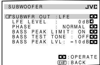
On this submenu, you can adjust subwoofer and bass sounds precisely according to your preference.
SUBWFR OUT
You can select the type of the signal which can be transmitted through the subwoofer. In other words, you can determine whether or not the bass elements of the front speaker channels are transmitted through the subwoofer regardless of the front speaker size setting (either "SMALL" or "LARGE").
Select one of the following:
LFE : Select to transmit only the LFE signals (while playing Dolby Digital and DTS software) and the bass elements of small speakers through the subwoofer.
LFE+MAIN: Select to always add the bass elements of the front speaker channels (MAIN) to the above (LFE), and to transmit them through the subwoofer.
Note:
If "SUBWOOFER" is set to "NO" on the SPEAKER SETTING submenu, this function is not available.
LFE LEVEL
If the bass sound is distorted while playing back software encoded with Dolby Digital or DTS, set the LFE level to eliminate distortion.
- This setting is also valid for THX Ultra2 Cinema, THX Music, DVD MULTI, and EXT 7.1CH.
Adjust the LFE level within the range of -20dB to 0 dB. (Normally select "0 dB.")
Each time you press (LEFT) or (RIGHT), the LFE level changes by ± 1 dB.
PHASE
If the sound output through the subwoofer is not satisfactory, changing the phase will give you a different result.
Select one of the following:
NORMAL : Normally select this.
REVERSE : Select this to reverse the phase.
Note:
If "SUBWOOFER" is set to "NO" on the SPEAKER SETTING submenu, this function is not available.
Continued on the next page
BASS PEAK LIMIT
When this setting is "ON," Bass Peak Limit functions so that sounds exceeding the preset peak level (see below) will be cut off.
When this setting is "ON," you can set the bass peak level using the bass test tone (see below) to eliminate bass sound distortion.
Select one of the following:
| ON : Normally select this. |
| OFF : Select when not using Bass Peak Limit. |
Note:
If "THX ULTRA2 SUBWOOFER?" is set to "YES," this function is not available.
BASS TEST TONE
Only when "BASS PEAK LIMIT" is "ON," you can emit the bass test tone through the subwoofer and/or other speakers (depending on your settings on the SPEAKER SETTING submenu), and adjust the bass peak level (see below).
- The bass test tone can be emitted when one of the Surround/THX/DSP modes is in use.
Select one of the following:
| ON | : Select to emit the bass test tone. |
| OFF | : Select to stop the bass test tone. |
Notes:
- If "BASS PEAK LIMIT" is set to "OFF," this function is not available.
- While transmitting the bass test tone, Parametric Equalizer and Midnight Mode will be canceled temporarily.
BASS PEAK LVL
Only when "BASS PEAK LIMIT" is "ON," you can set the bass peak level so that sounds exceeding the peak level will be cut off to prevent the bass sound distortion.
Adjust the bass peak level as follows:
- While listening to the bass test tone, press and hold (RIGHT) to increase the bass test tone output level, and stop increasing the level just before the test tone is distorted. The level where you stop can be memorized as the bass peak level.
Each time you press (RIGHT) or (LEFT), the bass peak level changes by ± 1 dB. - You can adjust the level within the range of “--dB (minimum),” and “-71 dB” to “+18 dB.” When shipped from the factory, the level is set at “-10 dB.”
Notes:
- When you set "BASS TEST TONE" to "ON," the bass peak level is reset to - - - dB (minimum).
- If "THX ULTRA2 SUBWOOFER?" is set to "YES," this function is not available.
Setting the THX Audio—THX AUDIO SETUP
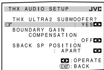
These settings are required to obtain the optimum effect from the THX modes.
Note:
When "SUBWOOFER" is set to "NO" on the SPEAKER SETTING submenu (see page 38), this submenu is not available in the following cases:
- If "SURR BACK SP" is also set to "NONE," or
- If "SURR BACK OUT" is also set to "1SPK."
THX ULTRA2 SUBWOOFER?
A THX Ultra2 certified subwoofer can reproduce very low bass sounds (up to 20Hz ) and, if it is used at home, the subwoofer sounds may be reinforced unsuitably because of resonance and reflection caused by the floor and walls (boundary gain).
Using this function, you can compensate for this over-enhanced bass sound through the subwoofer.
Select one of the following.
| YES : Select when a THX Ultra2 subwoofer is used. |
| NO : Select when a conventional subwoofer is used. |
BOUNDARY GAIN COMPENSATION
When the subwoofer sounds are unsuitably enhanced by so-called boundary gain, compensate for it using this function.
Select one of the following:
| ON | : Select to apply the compensation. |
| OFF | : Select when no compensation is required. |
Note:
If "THX ULTRA2 SUBWOOFER?" is set to "NO," this function is not available.
■ SBACK SP POSITION
Register the installation position of the surround back speakers—whether they are placed close to each other or apart from each other.
This setting takes effect only for the THX modes:
| APART | : Select when two surround back speakers are placed apart from each other (more than 120 cm). |
| CLOSE | : Select when two surround back speakers are placed to each other (from 30 cm to 120 cm). |
| TOGETHER: | Select when two surround back speakers are placed adjacent to each other (less than 30 cm)—recommended for THX Ultra2 Cinema and THX Music modes. |
Setting the Surround Channel Output Speakers—SURR CH OUT
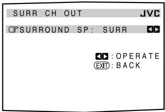
On this submenu screen, you can preset which surround speakers to use for 5.1 channel reproduction.
Note:
This submenu is not available in the following cases:
- When "SURR BACK OUT" is set to "1SPK" on the SPEAKER SETTING submenu,
- "SURR BACK SP" is set to "NONE" on the SPEAKER SETTING submenu,
- "SPEAKER 2" is set to "BI-AMP OUT" on the ZONE 2/SPEAKER 2 submenu, or
- When the Zone 2 speakers are activated.
SURROUND SP
Select the surround channel output speakers from the following:
| SURR | : Select to use the left and right surround speakers—recommended setting for Dolby Pro Logic and Pro Logic II. |
| SBACK | : Select to use only the surround back speakers. |
| SURR+SB | : Select to use both the surround speakers and surround back speakers. |
Setting the Audio Delay Level—AUDIO DELAY
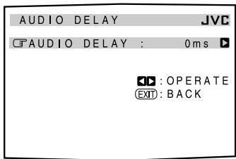
Synchronization between audio and video reproduction can be possibly disturbed because video signal decoding is time-consuming compared to the audio signal decoding.
On this submenu screen, you can correct synchronization between video and audio signals by delaying the audio signal timing.
AUDIO DELAY
Adjust the delay time within the range of 0 ms (initial setting: no effect) to 200 ms (maximum) in 20 ms intervals.
8 Selecting the Dual Mono Sound—DUAL MONO
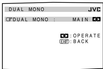
On this submenu screen, you can select the playback sound (channel) you want while playing digital software recorded (or broadcast) in the Dual Mono mode, which includes two monaural channels separately.
DUAL MONO
Select the playback sounds (channel).
| MAIN | : Select to play back the main channel (Ch1).*1 Signal indicator “L” lights up while playing back this channel. |
| SUB | : Select to play back the sub-channel (Ch2).*1 Signal indicator “R” lights up while playing back this channel. |
| ALL | : Select to play back both the main and sub-channels (Ch1/Ch2).*1 Signal indicators “L” and “R” light up while playing back these channels. |
Notes:
- The Dual Mono format is not identical with bilingual broadcasting or the MTS (Multi-channel TV Sound) format used for TV programs. So this setting does not take effect while watching bilingual or MTS programs.
*1 Dual Mono signals can be heard from the following speakers—L (left front speaker), R (right front speaker), and C (center speaker)—with respect to the current Surround setting.
| Dual Mono Setting | Without Surround | With Surround Activated | |||||
| Center speaker setting | |||||||
| LARGE/SMALL | NONE | ||||||
| L | R | L | C | R | L | R | |
| MAIN | Ch 1 | Ch 1 | — | Ch1 | — | Ch 1 | Ch 1 |
| SUB | Ch 2 | Ch 2 | — | Ch2 | — | Ch 2 | Ch 2 |
| ALL | Ch 1 | Ch 2 | — | Ch1+Ch2 | — | Ch1+Ch2 | Ch1+Ch2 |
Setting the Digital Input/Output Terminals —DIGITAL IN/OUT
When you use the digital input and output terminals on the rear, you have to register what components you have connected to these digital terminals.
COAX IN 1/2/3, OPT IN 4/5/6
Select the name of the component connected to each digital terminal so that it will correspond to the source selecting button on the unit and on the remote control.
Each time you press or (RIGHT or LEFT), the component name changes as follows:
DVD CD TV (or DBS*2) CDR MD VCR1 (back to the beginning)
Notes:
- If you have selected the same source for different terminals, only the last performed terminal setting will be valid. (The other terminal settings will be automatically set to "OFF.")
*2 If you have changed the source name from "TV" to "DBS," "DBS" appears (see page 27).
Continued on the next page
DIGITAL OUT
Select the output digital signal format through the DIGITAL OUT (optical) terminal on the rear.
Each time you press the button, the output signal format changes as follows:
| THROUGH : Select when connecting a digital signal processor or decoder. The incoming digital signals are transmitted through the digital output terminal without any processing. |
| PCM | : Select when connecting an MD recorder or other digital recording device. The incoming digital signals are down-mixed and converted into PCM format. |
10 Setting the Video Input Terminals —VIDEO INPUT
After connecting the video components to the video input terminals, you have to register which type of the terminal you have connected to—whether the component input or S-Video/ composite input.
Without setting this correctly, you may not view the pictures on the TV.
VIDEO INPUT
Select an appropriate input terminal used for each component—"DVD," "DBS," and "VCR1."
Each time you press (RIGHT) or (LEFT), the selected video input terminal changes as follows:
COMPO1 COMPO2 COMPO3 S/C (back to the beginning)
Notes:
- If you have selected the same component input terminal for different video components, only the last performed terminal setting will be valid. (The other terminal settings will be automatically set to "S/C.")
- If any of "COMPO 1/2/3" is selected for the video component which is only connected using S-video or composite video jacks (S/C), you cannot view or record its playback picture.
11 Turning On and Off the Video Output —VIDEO POWER
On this submenu screen, you can turn on or off the power supply to the video output circuit built in this unit.
VIDEO POWER
Turn on or off the power supply to the video output circuit.
ON : Normally select this.
Power is supplied to the built-in video output circuit.
OFF: Select to cut off power to the built-in video output circuit while playing an audio source.
With this setting, interference caused by the video output circuit will be reduced.
Note:
Even if "VIDEO POWER" is set to "OFF," power will be supplied to the video output circuit when on-screen display menus are used.
12 Setting the Zone 2/Speakers 2 Usage —ZONE 2/SPEAKER 2
On this submenu, you can determine the output signal type through the ZONE 2 PREOUT jacks, and the usage of the speaker connected to the FRONT 2/ZONE 2 SPEAKERS terminals.
ZONE2PREOUT
When connecting the Zone 2 front speakers to the ZONE 2 PREOUT jacks through another amplifier (see page 19), determine how to adjust the volume level in Zone 2.
Select one of the following:
| VARIABLE : Select when you want to adjust the Zone 2 volume level using the MASTER VOLUME control on this unit (or VOLUME +/- on this remote control). | |
| FIX : Select when you want to adjust the Zone 2 volume level using the amplifier connected to the ZONE 2 PREOUT jacks. · The MASTER VOLUME control on this unit (or VOLUME +/- on this remote control) cannot adjust the Zone 2 volume level. |
Note:
With "ZONE2PREOUT" set to "VARIABLE," no sounds come out of the ZONE 2 PREOUT jacks if the volume level is set to "--- dB." In this case, increasing the volume level will enable the sound output through the ZONE 2 PREOUT jacks.
SPEAKER 2
When using the FRONT 2/ZONE 2 SPEAKERS terminals, determine the speaker terminal usage:
SPEAKER 2 : Select to connect the second front speakers in Zone 1.
ZONE 2 SPK : Select to connect the front speakers in Zone 2.
BI-AMP OUT : Select to connect the front speakers in Zone 1 using bi-amplifier connection*.
The BI-AMP indicator (as well as the front speaker 1 indicator) will light up when the front speakers 1 are activated.
Notes:
- If your speaker has two pairs of input terminal (one for the high frequency range and the other for the low frequency range), you can connect the speakers by using both the FRONT 1 SPEAKERS and FRONT 2/ZONE 2 SPEAKERS terminals on the rear of this unit.
- When "BI-AMP OUT" is selected, the surround back speakers are automatically deactivated. In this case, the SURR CH OUT submenu cannot be adjusted (see page 42).
- When "BI-AMP OUT" is selected, "SURR BACK SP" is set to "NONE" on the SPEAKER SETTING submenu (see page 38).
Superimposing the Menus—SUPERIMPOSE
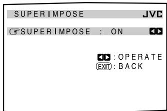
You can select whether or not to superimpose the menus on the playback pictures on the TV screen.
SUPERIMPOSE
Turn on or off superimpose:
ON : Select to superimpose the menus on the playback pictures on the TV screen.
OFF: Select to cancel superimposition.
- 100mm blue background screen.
Notes:
- If a video component and this unit are connected only using component cords, Superimpose will not work.
- While Superimpose is in use, the menus may fluctuate or may be distorted depending on the playback pictures. In this case, cancel superimpose by selecting "OFF."
14 Showing the Text Information on the Display—FL DISPLAY
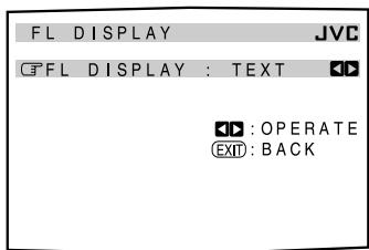
When you have connected an MD recorder or CD player equipped with the TEXT COMPU LINK remote control system (see page 63), you can show text information, such as disc title or track title, on the display of this receiver.
FL DISPLAY
Turn on or off the text information display.
TEXT : Text information appears during play.
NORMAL : Surround/THX/DSP mode appear during play.
Note:
Though you have selected "TEXT," the source name and Surround/THX/DSP mode will appear while playing a disc that has no text information.
15 Memorizing the Volume Level for Each Source—ONE TOUCH OPE
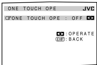
This unit memorizes many settings separately for each source (see page 28). In addition, you can store the volume level for each source together with the other memorized settings.
ONE TOUCH OPE
Select one of the following to store the volume level for each source:
ON : Select to store the volume level setting separately for each source. (The ONE TOUCH OPERATION indicator lights up on the main unit's display.)
This receiver memorizes the volume level
- when you turn on the power,
- when you change the source, and
- when you turn on One Touch Operation.
OFF : Select not to store the volume level setting.
To recall the volume level
With the ONE TOUCH OPERATION indicator lit, the volume level for the currently selected source is recalled when the source is selected.
To cancel the One Touch Operation
Set One Touch Operation to "OFF" so that the ONE TOUCH OPERATION indicator goes off.
Sound adjustment operations are only possible while the receiver is ready for Zone 1 operations.
Adjustment Menu Configuration
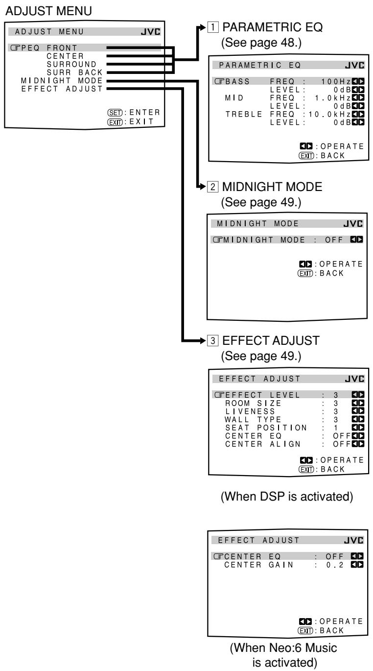
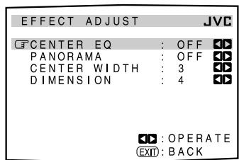
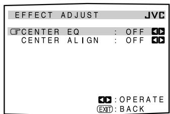
(When Pro Logic II Music is activated)
(When one of the other modes is activated, or when the source is "DVD MULTI" or "EXT 7.1CH")
NOTICE—
- If Analog Direct is in use (see page 27), you cannot make any sound adjustments using the Adjustment Menu.
- Items on the menus shown above are all set to the initial values when shipped from the factory.
- Some of the menus or some items on the menu cannot be shown or cannot be adjusted. (For details, see the respective explanations in this section.)
Note:
When performing sound adjustments viewing the indications on the main unit's display, the indications shown are slightly different from what are shown on the on-screen display.
This is because of the limited number of characters shown on the main unit's display.
Ex. “PEQ SURR BACK” is shown as “PEQ SBACK” on the main unit’s display.
- "TREBLE LEVEL" is shown as "TREBLE LVL" on the main unit's display.
IMPORTANT:
Check the following before or while using the buttons and controls.
For Zone 1 operations:
The ZONE 1 ON/OFF lamp on the unit is lit.
- When using the unit:
"ZONE 2" is not shown in the main display.
-Press DOOR DOWN to use the buttons inside the front door.
To close the front door, press DOOR UP.

DOOR DOWN
- When using the remote control:
- Set the ZONE 1/ZONE 2 (LEARN/TRANSMIT) selector to “ZONE 1.”
- Check the indication shown on the remote's display when you press a button—this indicates the remote control operation mode together with multi-room operation mode (either ZONE 1 or ZONE 2) for a while.
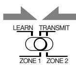

Ex. When you press ADJUST MENU with ZONE 1/ZONE 2 (LEARN/TRANSMIT) selector set to “ZONE 1.”
The buttons for operating the menus are shown on the screen. You can operate the menu with these buttons.
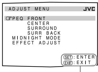
Usable buttons
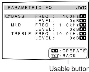
Operation through On-Screen Display Menus
To make sound adjustments for this receiver, you can utilize the on-screen display menus in order to finish important adjustments easily while viewing these menus.
Menu operation buttons
- When no operation is done for about 1 minute, the on-screen menu (as well as the indications in the unit's main display) will disappear.
On the unit:
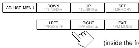
(inside the front door)
| Button | To do |
| ADJUST MENU | display or erase the Adjustment Menu. |
| DOWN/UP | select a submenu on the Adjustment Menu or an item on a submenu (downwards or upwards). |
| SET | move to the selected submenu screen. |
| LEFT/RIGHT | select the desired setting on a submenu. |
| EXIT | exit from menu operations or return to the previous menu. |
From the remote control:
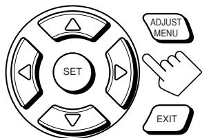
| Button | To do |
| ADJUST MENU | display or erase the Adjustment Menu. |
| ∇ / ∅ | select a submenu on the Adjustment Menu or an item on a submenu (downwards or upwards). |
| SET | move to the selected submenu screen. |
| < / > | select the desired setting on a submenu. |
| EXIT | exit from menu operations or return to the previous menu. |
Menu Operating Procedure
Ex. When adjusting the DSP effects
Operations
1. Press ADJUST MENU.
- Make sure one of the DSP modes except "ALL CH STEREO" is selected.
On the TV screen
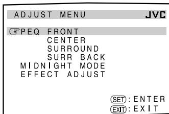
On the main unit's display
PEO FRONT
SPEAKERS 1 VOLUME
1 1
The submenu names previously selected appears.
ADJUST MENU appears.
2. Press or (DOWN or UP) repeatedly to select the desired submenu.
- In this example, select "EFFECT ADJUST" submenu.
Move 3 to "EFFECT ADJUST."
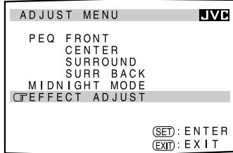
Press the button until "EFFECT ADJ" appears.
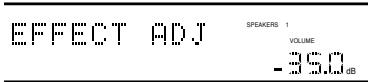
3. Press SET.
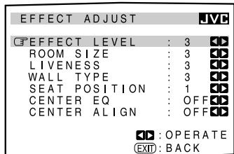
The selected submenu appears.
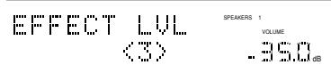
The first item on the selected submenu appears (with the current setting shown on the lower line of the main display).
4. Set a desired item on the submenu.
① Press or (DOWN or UP) repeatedly to select an item.
② Press or (RIGHT or LEFT) to set the item.
- In this example, set "ROOM SIZE" to "5."
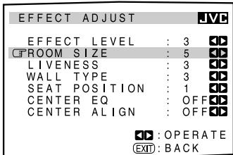
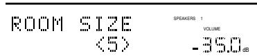
5. Set other items on the same submenu if necessary.
① Press or (DOWN or UP) repeatedly to select another item on the same submenu.
② Press or (RIGHT or LEFT) to set the item.
- In this example, set "LIVENESS" to "5."
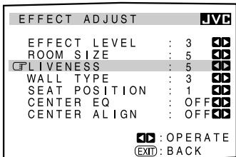
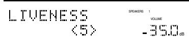
To return to the previous screens
Press EXIT.
Each time you press the button, the on-screen display menu returns to the one previously displayed. (On the main unit's display, the indications also change accordingly.)
To erase the menu (to return to the regular screen)
Press ADJUST MENU.
Adjusting the Parametric Equalizer for Each Channel—PEQ FRONT/CENTER/SURROUND/SURR BACK
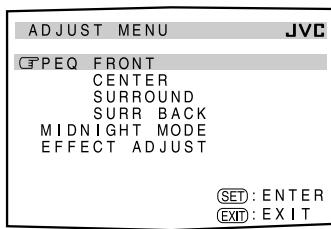
You can adjust equalization patterns to your preference. First, on the ADJUST MENU screen, select the signal channel (speaker) you want to adjust, then move to its submenu.
Notes:
- This function is applied only to Zone 1 sources.
- If "NO" or "NONE" is selected for a speaker on the SPEAKER SETTING submenu (see page 38), you cannot select the corresponding channel.
- If THX is activated, Parametric Equalizer is not available.
- If "EXT 7.1CH" is selected as the source, Parametric Equalizer for the surround back channel is not available.
Adjustment procedure
1 Press or (DOWN or UP) to select the channel—PEQ FRONT, CENTER, SURROUND, or SARR BACK, then press SET.
The submenu of the selected channel appears.
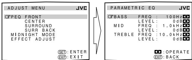
2 Press or (DOWN or UP) to select an item you want to adjust on the submenu.
3 Press or (RIGHT or LEFT) to adjust the item.
- Once one of the sound levels—"BASS LEVEL," "MID LEVEL" and "TREBLE LEVEL"—is adjusted, the PARAMETRIC EQ indicator lights up on the display.
4 Repeat steps 2 and 3 to adjust the other items on the same submenu.
5 Press EXIT once.
The ADJUST MENU appears again.
6 Repeat steps 1 to 5 to adjust the other channels.
To cancel the adjustment, set all the sound levels—"BASS LEVEL," "MID LEVEL" and "TREBLE LEVEL"—to "0 dB." The PARAMETRIC EQ indicator goes off.
Submenu items
On this submenu, you can adjust the following items for each channel:
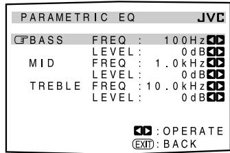
BASS FREQ*: Select the center frequency to adjust bass sounds from—63 Hz, 80 Hz, 100 Hz (initial), 125 Hz, 160 Hz, 200 Hz, 250 Hz, 320 Hz, 400 Hz, 500 Hz, 630 Hz, 800 Hz, 1.0 kHz.
LEVEL : Adjust the enhancement level for bass sounds (within the range of +6 dB to -6 dB).
MID FREQ*: Select the center frequency to adjust middle-range sounds from—250 Hz, 320 Hz, 400 Hz, 500 Hz, 630 Hz, 800 Hz, 1.0 kHz (initial), 1.25 kHz, 1.6 kHz, 2.0 kHz, 2.5 kHz, 3.2 kHz, 4.0 kHz.
LEVEL : Adjust the enhancement level for middle-range sounds (within the range of +6 dB to -6 dB).
TREBLE FREQ*: Select the center frequency to adjust treble sounds from—1.0 kHz, 1.25 kHz, 1.6 kHz, 2.0 kHz, 2.5 kHz, 3.2 kHz, 4.0 kHz, 5.0 kHz, 6.3 kHz, 8.0 kHz, 10.0 kHz (initial), 12.5 kHz, 16.0 kHz.
LEVEL : Adjust the enhancement level for treble sounds (within the range of +6 dB to -6 dB).
Note:
- Adjustable range changes according to the other two frequency settings.
Setting the Midnight Mode—MIDNIGHT MODE
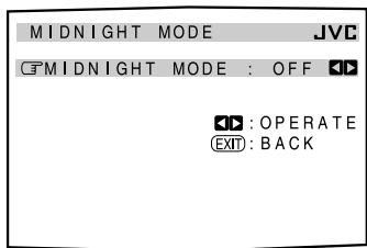
Using the Midnight mode, you can enjoy a powerful sound at night even at a low volume level.
MIDNIGHT MODE
Select one of the following:
1 : Select when you want to reduce the dynamic range a little. The MIDNIGHT MODE indicator lights up on the display.
2 : Select when you want to apply the compress effect fully (useful late at night). The MIDNIGHT MODE indicator lights up on the display.
OFF: Select when you want to enjoy surround with its full dynamic range (no effect applied). The MIDNIGHT MODE indicator goes off from the display.
Notes:
- This function is applied only to Zone 1 sources.
- If Analog Direct is in use, Midnight mode is temporarily canceled.
- The MIDNIGHT MODE indicator goes off when one of the THX modes is activated. However, this function is still active if the playback source is Dolby Digital or DTS encoded software. (If the source is analog or digital PCM software, Midnight mode is canceled.)
3 Adjusting the Various Effects EFFECT ADJUST
On these submenus, you can adjust various effects for each DSP and Surround mode (except the THX modes).
Notes:
- This submenu is not available when "ALL CH STEREO" is selected.
- This submenu settings are memorized for each DSP and Surround mode (including multi-channel playback modes—"DVD MULTI" and "EXT 7.1CH" with the DSP mode turned off).
-
You cannot adjust these various effects in the following cases:
-
When Analog Direct is turned on.
- When the THX mode is turned on.
- When the Surround or DSP mode is turned off, or
- When "3D HEADPHONE" or "HEADPHONE" mode is turned on.
Submenu items
Adjustable items on the submenu depend on what mode is currently selected.
- If "NONE" is selected for the center speaker on the SPEAKER SETTING submenu (see page 38), no adjustments related to the center channel are available—"CENTER EQ," "CENTER ALIGN," "CENTER WIDTH," and "CENTER GAIN."
- When one of the DSP modes (except "ALL CH STEREO") is activated:
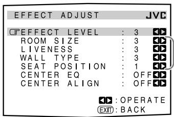
When the surround speakers are deactivated, these adjustments are not available.
Select and adjust the following items:
EFFECT LEVEL: Adjust the DSP effect level. As the number increases, the DSP effect becomes stronger. (Normally select "3." Adjustable range: 1 to 5)
ROOM SIZE: Adjust the virtual room size. As the number increases, the interval between reflections increases so that you will feel as if you are in a larger room. (Normally select "3." Adjustable range: 1 to 5)
LIVENESS: Adjust the liveness effect. As the number increases, the attenuation level of reflections over time decreases so that acoustics change from "Dead" to "Live." (Normally select "3." Adjustable range: 1 to 5)
WALL TYPE: Adjust the wall type. As the number increases, the hardness of the wall to be simulated ranges from "soft" to "hard." (Normally select "3." Adjustable range: 1 to 5)
SEAT POSITION: Select either 1 or 2 according to your preference as if you change your seat in a theater, hall, recital hall, church, etc.
CENTER EQ: In movie theaters, the screen works as the high-frequency cut filter of the center channel since the center speakers are located behind the screen and the center channel sounds have to pass through the screen.
- Select "ON" to cut off the high frequency of the center channel as is done in a real movie theater.
- Select "OFF" not to use this function.
CENTER ALIGN: Align the vertical localization of the center channel signals (mainly human voices are recorded) at the same height as for the front speakers.
- Select "ON" when you cannot feel as if the actors or singers are speaking or singing on the screen.
-
Select "OFF" not to use this function.
-
When Dolby Pro Logic II Music is activated:

Select and adjust the following items:
CENTER EQ: In movie theaters, the screen works as the high-frequency cut filter of the center channel since the center speakers are located behind the screen and the center channel sounds have to pass through the screen.
- Select "ON" to cut off the high frequency of the center channel as is done in a real movie theater.
- Select "OFF" not to use this function.
PANorama: Extend the front stereo image to include the surround speakers for an exciting "wraparound" effect with side wall imaging.
- Select "ON" to turn on this function.
- Select "OFF" not to use this function.
CENTER WIDTH: Adjust the center image so it may be heard only from the center speaker, only from the left/right speakers as a “phantom” center image, or various combinations of all three front speakers. As the number increases, the “phantom” effect become stronger. (Normally select “3.” Adjustable range: OFF, 1 to 7)
- Select "OFF" not to use this function.
DIMENSION: Allows you to gradually adjust the sound field either towards the front or towards the rear. As the number increases, the sound field moves towards the front. (Normally select "4." Adjustable range: 1 to 7)
- When Neo:6 Music is activated:
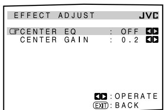
Select and adjust the following items:
CENTER EQ: In movie theaters, the screen works as the high-frequency cut filter of the center channel since the center speakers are located behind the screen and the center channel sounds have to pass through the screen.
- Select "ON" to cut off the high frequency of the center channel as is done in a real movie theater.
- Select "OFF" not to use this function.
CENTER GAIN: Adjust the sound localization of the center channel. As the number increases, center channel will be localized clearly.
(Normally select "0.2." Adjustable range: 0 to 0.5)
- When one of the other Surround modes is activated, or "DVD MULTI" or "EXT 7.1CH" is selected (without DSP mode):
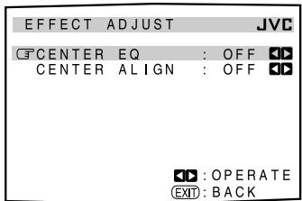
Select and adjust the following items:
CENTER EQ: In movie theaters, the screen works as the high-frequency cut filter of the center channel since the center speakers are located behind the screen and the center channel sounds have to pass through the screen.
- Select "ON" to cut off the high frequency of the center channel as is done in a real movie theater.
- Select "OFF" not to use this function.
CENTER ALIGN: Align the vertical localization of the center channel signals (mainly human voices are recorded) at the same height as for the front speakers.
- Select "ON" when you cannot feel as if the actors or singers are speaking or singing on the screen.
- Select "OFF" not to use this function.
To adjust the DSP effect levels using the 10 keys
You can also use the 10 keys on the remote control to adjust the DSP effect levels ("EFFECT" and "LIVENESS").
Once you adjust their levels using the following procedure, the adjustments you have done on the Adjustment Menu will be also changed.
From the remote control ONLY:
- Press SOUND.
The 10 keys are activated for sound adjustments.
- Press EFFECT repeatedly to adjust the overall level of the effect (1 to 5).

EFFECT
- Press LIVENESS repeatedly to adjust the liveness (1 to 5).
LIVENESS
Using the Surround and THX Modes
This unit activates a variety of Surround and THX modes automatically. The stored basic settings and adjustments performed on the Setup and Adjustment Menus (see pages 35 to 50) are applied.
- The following operations are only possible when the receiver is ready for Zone 1 operations, and are used only for Zone 1 sources.
Reproducing Theater Ambience
In a movie theater, many speakers are located on the walls to reproduce impressive multi-surround sounds, reaching you from all directions.
With these many speakers, sound localization and sound movement can be expressed.
Surround modes built in this receiver can create almost the same surround sounds as you can feel in a real movie theater—with only five or seven speakers (plus subwoofer).
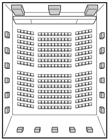

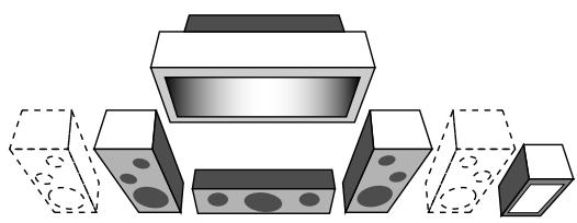


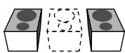
Note:
When the ZONE 2 speaker indicator is lit on the display, you cannot use the THX modes and Surround modes requiring the surround back speakers.
You can only use those modes which do not require the surround back speakers.
Introducing the Surround and THX Modes
Home THX\*1
Home THX Audio Systems, developed by THX Ltd., has become the world's standard for film enjoyment in the home. It is one of the multi-channel home entertainment systems to reproduce all multichannel sources accurately in the home.
In newly developed THX Ultra2 Cinema Mode or THX Music Mode, all multi-channel software (5.1 channels or more) is automatically detected and proper processing is applied to improve directional and ambient surround information through four surround speakers—two at the side and two at the back.
- This receiver provides four types of THX modes—THX Ultra2 Cinema (THX U2 CINEMA), THX Music (THX MUSIC), THX Surround EX (THX SURR EX), THX Cinema (THX CINEMA). When any one of the THX modes is activated, the indicator lights up on the display.
| THX Ultra2 Cinema : Best for playing any 5.1-channel encoded movie software, this mode can stabilize the sound localization and enlarge the sound field. (Only selectable with a pair of surround back speakers.) |
| THX Music : Best for playing any 5.1-channel encoded music software. (Only selectable with a pair of surround back speakers.) |
| THX Surround EX : Best for playing Dolby Digital EX encoded software. (Only selectable with one or a pair of surround back speakers.) |
| THX Cinema | : To reproduce the sound through all activated speakers except surround back speakers. (When THX Cinema is applied to Neo: 6 Cinema, sounds can also be emitted from the surround back speakers.) |
- THX modes can be also applied to any source together with another Surround mode.
Dolby Digital*2
Dolby Digital is a digital signal compression method, developed by Dolby Laboratories, and enables multi-channel encoding and decoding (1ch up to 5.1ch).
- When a Dolby Digital signal is detected through the digital input, the DIGITAL indicator lights up on the display.
Dolby Digital 5.1CH
Dolby Digital 5.1CH (DOLBY DIGITAL) encoding method records and digitally compresses the left front channel, right front channel, center channel, left surround channel, right surround channel, and LFE channel signals (total 6 channels, but the LFE channel is counted as 0.1 channel. Therefore, called 5.1 channel). Dolby Digital enables stereo surround sounds, and sets the cutoff frequency of the surround treble at 20kHz , compared to 7kHz for Dolby Pro Logic. As such, the sound movement and "being-there" feeling are enhanced much more than Dolby Pro Logic.
Dolby Digital EX
Dolby Digital EX (DOLBY D EX) is a new digital surround encoding format that adds the third surround channels, called "surround back."
Compared to the conventional Dolby Digital 5.1CH, the newly added surround back channel can reproduce more detailed movements behind you while viewing the video software. In addition, surround sound localization will become more stable.
Dolby Pro Logic
Dolby Surround encoding format records the left front channel, right front channel, center channel, and surround channel (monaural) signals into 2 channels.
The Dolby Pro Logic (PRO LOGIC) built in this receiver decodes these 2 channel signals into 4 original channel signals (plus subwoofer)—matrix-based multi-channel reproduction.
- When Dolby Pro Logic is activated, the DPL indicator lights up on the display.
- THX Cinema can be applied together with Pro Logic when an analog or digital 2-channel software is played back.
Dolby Pro Logic II
Dolby Pro Logic II has a newly developed multi-channel playback format to convert 2-channel software into 5-channel (plus subwoofer). The matrix-based conversion method used for Dolby Pro Logic II makes no limitation for the cutoff frequency of the surround treble and enables stereo surround sound.
- This receiver provides two types of Dolby Pro Logic II modes—Pro Logic II Movie (PLII MOVIE) and Pro Logic II Music (PLII MUSIC).
When Dolby Pro Logic II is activated, the indicator lights up on the display.
| Pro Logic II Movie : | Suitable for playing any Dolby Surround encoded software. You can enjoy a sound field very close to the one created with discrete 5.1-channel sounds. |
| Pro Logic II Music : Suitable for playing any 2-channel stereo software. You can enjoy wide and deep sounds. |
- THX Cinema can be applied together with Pro Logic II Movie when an analog or digital 2-channel software is played back.
DTS*3
DTS is another digital signal compression method, developed by Digital Theater Systems, Inc., and enables multi-channel encoding and decoding (1ch up to 6.1ch).
- When a DTS signal is detected through the digital input, the indicator lights up on the display.
DTS Digital Surround
DTS Digital Surround (DTS SURROUND) is another discrete 5.1 channel digital audio format available on CD, LD, and DVD software.
Compared to Dolby Digital, the DTS Digital Surround format has a lower audio compression rate which enables it to add breadth and depth to the sounds reproduced. As such, DTS Digital Surround features natural, solid and clear sound.
- When 7.1-channel reproduction mode (EX/ES/7.1) is set to "ON," DTS Neo:6 (DTS NEO:6) is applied while playing back multi-channel DTS software. It creates the same surround ambience as playing 6.1-channel software.
DTS Extended Surround (DTS-ES)
DTS-ES is another new multi-channel digital encoding format. It greatly improves the 360-degree surround impression and space expression by adding the third surround channel—surround back channel.
DTS-ES includes two signal formats with different surround signal recording methods—DTS-ES Discrete 6.1ch (DTS-ES DSCRT) and DTS-ES Matrix 6.1ch (DTS-ES MATRIX).
DTS-ES Discrete 6.1ch has been designed to encode (and decode) a 6.1-channel signal discretely to avoid interference with each channel.
DTS-ES Matrix 6.1ch has been designed to add an extra surround channel to DTS Digital Surround 5.1-channel. By using a matrix encoding/decoding method, an additional "surround back" channel signal is encoded (and decoded) in both the left and right surround channel signals.
DTS 96/24
In recent years, there has been increasing interest in higher sampling rates both for recording and for reproducing at home. Higher sampling rates allow wider frequency range and greater bit depths provide extended dynamic range.
DTS 96/24 is a multi-channel digital signal format (fs 96kHz / 24 bits) introduced by Digital Theater Systems, Inc. to deliver "better-than-CD sound quality" into the home.
- When DTS 96/24 signals are detected, the 96/24 indicator lights up. You can enjoy its 5.1-channel sound with full-quality.
DTS Neo:6
DTS Neo:6 is a newly developed conversion method to create 6-channel (plus subwoofer) from analog/digital 2-channel software and DTS Digital Surround software by using the high precision digital matrix decoder used for DTS-ES Matrix 6.1ch.
- This receiver provides two types of DTS Neo:6 modes—Neo:6 Cinema (NEO:6 CINEMA) and Neo:6 Music (NEO:6 MUSIC). When either Neo:6 mode is activated, the Neo:6 indicator lights up on the display.
| Neo:6 Cinema :Suitable for playing movies. You can get the same atmosphere with 2-channel software as with 6.1-channel software. It is also effective for playing software encoded with conventional surround formats. |
| Neo:6 Music :Suitable for playing music software. The front channel signals bypass the decoder (resulting in no loss of sound quality) and the surround signals transmitted through the other speakers expand the sound field naturally. |
- THX Cinema can be applied together with Neo:6 Cinema when an analog or digital 2-channel software is played back.
About Dual Mono
This format is now adopted in Dolby Digital, DTS, and so on. When Dual Mono signals are detected, "DUAL MONO" appears, and the DUAL indicator lights up on the display.
See page 24 for more details.
1 THX and THX Ultra2 are registered trademarks of THX Ltd.
Surround EX is a trademark of Dolby Laboratories, Inc. Used under authorization.
2 Manufactured under license from Dolby Laboratories. "Dolby", "Pro Logic", "Surround EX", and the double-D symbol are trademarks of Dolby Laboratories.
*3 "DTS", "DTS-ES Extended Surround" and "Neo:6" are trademarks of Digital Theater Systems, Inc.
Surround and THX Modes Applicable to the Various Software
Available Surround modes and THX modes vary depending on the speaker settings and the incoming signals.
The tables from this page to the next page show the relation of the Surround/THX modes and the incoming signals (with the Zone 2 speakers, surround back speakers, and 7.1-channel reproduction mode settings).
- If only front speakers are activated, you cannot use the THX modes and the 7.1-channel reproduction mode (ES/EX/7.1).
- The numbers inside the parentheses under the incoming signal type indicate the number of the front channels and that of the surround channels. For example, (3/2) indicates that the signals are encoded with three front signals (left/right/center) and two (stereo) surround signals.
| Incoming Signal Type (multi-channel) | Zone 2 Speakers | Surround Back Ch (NONE/1SPK/2SPK) | ES/EX/7.1 (AUTO/ON/OFF) | Available Surround Mode | Available THX Mode |
| Dolby Digital EX | ON | Not available | Not available | DOLBY DIGITAL | THX CINEMA |
| OFF | 2SPK/1SPK | AUTO | DOLBY D EX | THX SURR EX | |
| ON | DOLBY D EX | THX SURR EX | |||
| OFF | DOLBY DIGITAL | THX CINEMA | |||
| NONE | Not available | DOLBY DIGITAL | THX CINEMA | ||
| Dolby Digital (3/2, 2/2) | ON | Not available | Not available | DOLBY DIGITAL | THX CINEMA |
| OFF | 2SPK | AUTO | DOLBY DIGITAL | THX U2 CINEMA | |
| ON | DOLBY D EX | THX MUSIC | |||
| OFF | DOLBY DIGITAL | THX CINEMA | |||
| 1SPK | AUTO | DOLBY DIGITAL | THX CINEMA | ||
| ON | DOLBY D EX | THX SURR EX | |||
| OFF | DOLBY DIGITAL | THX CINEMA | |||
| NONE | Not available | DOLBY DIGITAL | THX CINEMA | ||
| Dolby Digital (3/1, 2/1) | ON | Not available | Not available | DOLBY DIGITAL | THX CINEMA |
| OFF | 2SPK | AUTO | DOLBY DIGITAL | THX U2 CINEMA | |
| ON | DOLBY DIGITAL | THX MUSIC | |||
| OFF | DOLBY DIGITAL | THX CINEMA | |||
| 1SPK | AUTO | DOLBY DIGITAL | THX CINEMA | ||
| ON | DOLBY DIGITAL | THX CINEMA | |||
| OFF | DOLBY DIGITAL | THX CINEMA | |||
| NONE | Not available | DOLBY DIGITAL | THX CINEMA | ||
| Dolby Digital (1/0, 3/0) | ON/OFF | Not available | Not available | DOLBY DIGITAL | THX CINEMA |
| Dolby Digital (Dual Mono) | ON/OFF | Not available | Not available | DUAL MONO | Not available |
- For Dolby Digital 2-channel (2/0) and Dolby Surround, see "Incoming Signal Type (2-channel)" on the next page.
| Incoming Signal Type (multi-channel) | Zone 2 Speakers | Surround Back Ch (NONE/1SPK/2SPK) | ES/EX/7.1 (AUTO/ON/OFF) | Available Surround Mode | Available THX Mode |
| DTS-ES Discrete 6.1ch | ON | Not available | Not available | DTS SURROUND | THX CINEMA |
| OFF | 2SPK/1SPK | AUTO | DTS-ES DSCRT | THX ES DSCRT | |
| ON | DTS-ES DSCRT | THX ES DSCRT | |||
| OFF | DTS SURROUND | THX CINEMA | |||
| NONE | Not available | DTS SURROUND | THX CINEMA | ||
| DTS-ES Matrix 6.1ch (without DTS 96/24) (with DTS 96/24) | ON | Not available | Not available | DTS SURROUND | THX CINEMA |
| OFF | 2SPK/1SPK | AUTO | DTS-ES MATRIX *1 | THX ES MATRIX *1 | |
| ON | DTS-ES MATRIX *1 | THX ES MATRIX *1 | |||
| OFF | DTS SURROUND | THX CINEMA | |||
| NONE | Not available | DTS SURROUND | THX CINEMA | ||
| DTS, DTS 96/24 (3/2, 2/2) | ON | Not available | Not available | DTS SURROUND | THX CINEMA |
| OFF | 2SPK | AUTO | DTS SURROUND | THX U2 CINEMA | |
| THX MUSIC | |||||
| *1 DTS 96/24 processing is not be applied. If you want to apply the processing, set the EX/ES/7.1 setting to “OFF.” | ON | DTS NEO:6 *1 | THX DTS NEO:6 *1 | ||
| THX U2 CINEMA | |||||
| THX MUSIC | |||||
| 1SPK | AUTO | DTS SURROUND | THX CINEMA | ||
| ON | DTS NEO:6 | THX DTS NEO:6 | |||
| OFF | DTS SURROUND | THX CINEMA | |||
| NONE | Not available | DTS SURROUND | THX CINEMA | ||
| DTS (3/1, 2/1) | ON | Not available | Not available | DTS SURROUND | THX CINEMA |
| OFF | 2SPK | AUTO | DTS SURROUND | THX U2 CINEMA | |
| THX MUSIC | |||||
| ON | DTS SURROUND | THX U2 CINEMA | |||
| THX MUSIC | |||||
| OFF | DTS SURROUND | THX CINEMA | |||
| 1SPK | AUTO | DTS SURROUND | THX CINEMA | ||
| ON | DTS SURROUND | THX CINEMA | |||
| OFF | DTS SURROUND | THX CINEMA | |||
| NONE | Not available | DTS SURROUND | THX CINEMA | ||
| DTS (1/0, 3/0) | ON/OFF | Not available | Not available | DTS SURROUND | THX CINEMA |
| DTS (Dual Mono) | ON/OFF | Not available | Not available | DUAL MONO | Not available |
- For DTS 2-channel (2/0) , see "Incoming Signal Type (2-channel)" below.
| Incoming Signal Type (2-channel) | Available Surround Mode |
| Analog/PCM/Dolby Digital/DTS/Dolby Surround | PLII MOVIE / PLII MUSIC / PRO LOGIC / NEO:6 CINEMA / NEO:6 MUSIC |
| Analog Multi-channel (DVD MULTI, EXT 7.1CH) | None |
| Available THX Mode | |
| Analog/PCM/Dolby Digital/DTS/Dolby Surround | PLIIMOVIE THX / PROLOGIC THX / NEO:6 C THX |
| Analog Multi-channel (DVD MULTI, EXT 7.1CH) | THX U2 CINEMA*2 / THX MUSIC*2 |
*2 Available only when a pair of surround back speakers can be used.
Activating the Surround and THX Modes
Perform the basic settings and adjustments using the Setup and Adjustment Menus first (see pages 35 to 50).
Activating the Surround mode and the THX mode for a source automatically recalls the memorized settings and adjustments.
IMPORTANT:
Check the following before or while using the buttons and controls.
For Zone 1 operations:
The ZONE 1 ON/OFF lamp on the unit is lit.
- When using the unit:
"ZONE 2" is not shown in the main display.
-Press DOOR DOWN to use the buttons inside the front door.
To close the front door, press DOOR UP.
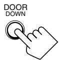
- When using the remote control:
- Set the ZONE 1/ZONE 2 (LEARN/TRANSMIT) selector to “ZONE 1.”
- Check the indication shown on the remote's display when you press a button—this indicates the remote control operation mode together with multi-room operation mode (either ZONE 1 or ZONE 2) for a while.

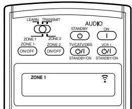
Ex. When you press THX with ZONE 1/ZONE 2 (LEARN/TRANSMIT) selector set to “ZONE 1.”
About Dialog Normalization
Dialog Normalization is one of the standard functions for Dolby Digital and its level is encoded together with the audio signals. With this function, the sound output level of Dolby Digital software can be kept at almost the same level even if the recording levels differ among software.
If you see a message in the main display that shows "DIAL. NORM: XX (number)" this means that the source material that you are listening to has been encoded at a higher or lower level than normal. To keep the volume level consistent from program to program, adjust the volume control by the amount (XX) in this message.
- Ex: If the display reads "DIAL. NORM: +4", turn down the volume control by 4 dB.
Activating the 7.1-channel reproduction
For multi-channel digital software, you can activate the 7.1-channel reproduction mode.
- Once you have set 7.1-channel reproduction mode, it is stored in memory and will be called up whenever you activate the Surround mode or THX mode which the memorized 7.1-channel reproduction mode can be applied to.
Press EX/ES/7.1 to select an appropriate setting for your enjoyment.
The currently selected 7.1-channel reproduction mode appears on the display.
Each time you press the button, it changes as follows:
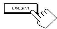
From the remote control
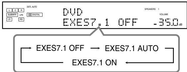
On the unit (inside the front door)
EXES7.1 AUTO
: According to the incoming signal, an appropriate Surround mode is applied.
- For 6.1-channel encoded software, 7.1-channel reproduction is applied
- For 5.1-channel (or less) encoded software, 5.1-channel reproduction is applied.
EXES7.1 ON
: Select to apply 7.1-channel reproduction to both 5.1-channel and 6.1-channel encoded software.
EXES7.1 OFF
: Select to cancel the 7.1-channel reproduction.
Notes:
- When an analog or digital 2-channel source is playing with Surround activated, you can adjust the 7.1-channel reproduction mode and store the setting, but it will not affect the current source.
-
In the following cases, the EX/ES/7.1 button does not work. ("NO SURRBACK" appears on the display.)
-
When "SURR BACK SP" is set to "NONE" (see page 38), or
- When "SPEAKER 2" is set to "BI-AMP OUT" (see page 44)
- When the Zone 2 speakers are activated, the EX/ES/7.1 button does not work. ("EXES7.1 OFF" appears on the display.)
Activating the Surround Modes
For the Surround modes, Parametric Equalizer adjustments done on the Adjustment menu also take effect for the activated speaker channels.
- Available Surround modes vary depending on the received signal and the current speaker settings. For details, see "Surround and THX Modes Applicable to the Various Software" on pages 53 and 54.
1. Select and play any source other than "DVD MULTI" and "EXT 7.1CH."
- Surround modes are not applicable to "DVD MULTI" and "EXT 7.1CH."
2. Press SURROUND to activate the Surround mode.
On the unit (inside the front door)
From the remote control
- For multi-channel digital software (except 2-channel and Dual Mono software), either "DOLBY DIGITAL" or "DTS SURROUND" is activated.
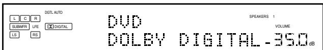
Ex. When "DOLBY DIGITAL" is activated.
-
If the 7.1-channel reproduction (EX/ES/7.1) mode has been set to "AUTO" or "ON," one of the 7.1-channel reproduction modes will be activated.
-
For analog sources and digital 2-channel software, you can select one of the following Surround modes. Each time you press SURROUND, Surround modes change as follows:
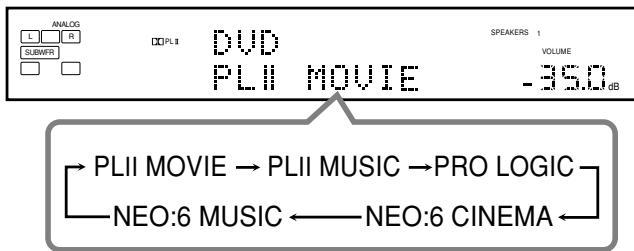
- For Dual Mono software, speaker output channel changes to the center speaker if it is connected and activated.
(You can select the channel you listen to. See page 42.)
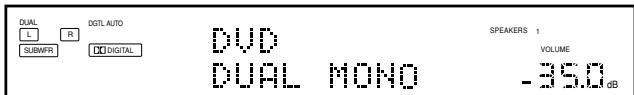
Notes:
- While listening with the headphones, "3D HEADPHONE" will appear on the display. (The DSP and HEADPHONE indicators will light up.)
- If the THX mode or DSP mode is in use, it will be canceled when you turn on the Surround mode.
To adjust the speaker output level using the remote control, follow the procedure below.
- When Analog Direct is in use, you cannot adjust the speaker output levels without emitting the test tone (see page 39).
From the remote control ONLY:
1. Press SOUND.
The 10 keys are activated for sound adjustments.
2. Select the speaker you want to adjust.
The selected speaker name appears on the remote's display for a while.
To select the left front speaker, press FRONT · L.
- To select the center speaker, press CENTER.
To select the right front speaker, press FRONT · R.
To select the right surround speaker, press SURR · R.
To select the right surround back speaker, press SURR BK·R.
To select the left surround back speaker, press SURR BK · L.
- To select the left surround speaker, press SURR · L.
- To select the subwoofer, press SUBWFR.
3. Press LEVEL + / - to adjust the speaker output levels.
The speaker name selected in the above step and its level appear on the unit's display.
-
You can adjust the levels within the range of -10 dB to +10 dB.
-
Repeat steps 2 and 3 to adjust the other speaker output levels.
To cancel the Surround mode
Press SURR/DSP OFF.
"SURROUND OFF" appears on the display.

On the unit (inside the front door)
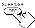
From the remote control

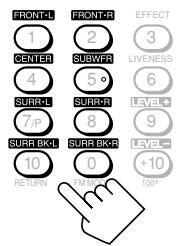

Activating the THX Modes
When one of the THX modes is activated, Parametric Equalizer and CC Converter are temporarily canceled.
- Available THX modes vary depending on the received signal and the current speaker settings. For details, see "Surround and THX Modes Applicable to the Various Software" on pages 53 and 54.
1. Select and play any source other than "DVD MULTI" and "EXT 7.1CH."
- To use the THX modes for "DVD MULTI" and "EXT 7.1CH," see page 60.
2. Press THX to activate the THX mode.
- If the Surround mode is deactivated, it is automatically activated with an appropriate mode selected.
On the unit (inside the front door)

From the remote control
- For multi-channel digital software (except 2-channel and Dual Mono sources), one of the appropriate THX modes is activated (see the tables on pages 53 and 54).
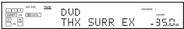
Ex. When "DVD" with its digital input is selected.
- If the 7.1-channel reproduction (EX/ES/7.1) mode has been set to "AUTO" or "ON," one of the 7.1-channel reproduction modes will be activated.
-
You can change the THX modes manually for some of the multi-channel software. In this case, press THX repeatedly until the THX mode you want appears.
-
For analog 2-channel sources and digital 2-channel software, you can select one of the following THX/Surround modes. Each time you press THX, THX/ Surround modes change as follows:
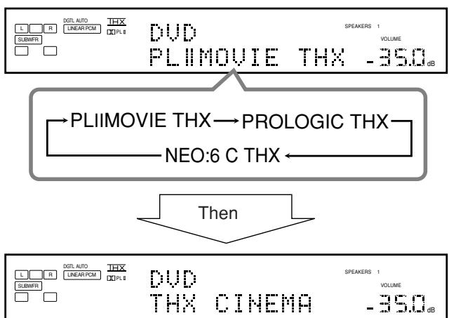
Note:
If the DSP mode is in use, it will be canceled when you turn on the THX mode.
| PLIIMOVIE THX : Select to apply Pro Logic II Movie and THX Cinema mode together. · If Pro Logic II Music or Pro Logic II Movie is activated before activating the THX mode, it also changes to this mode. | |
| PROLOGIC THX : Select to apply Pro Logic and THX Cinema mode together. · If Pro Logic is activated before activating the THX mode, it also changes to this mode. | |
| NEO:6 C THX : Select to apply Neo:6 Cinema and THX Cinema mode together. · If Neo:6 Music or Neo:6 Cinema is activated before activating the THX mode, it also changes to this mode. |
To adjust the speaker output level using the remote control, see page 56.
To cancel the THX mode without canceling the Surround mode
Press SURROUND so that the last selected Surround will be activated (the currently selected THX mode will be canceled).
On the unit (inside the front door)

From the remote control
To cancel the THX and Surround modes
Press SURR/DSP OFF.
"SURROUND OFF" appears on the display.

On the unit (inside the front door)
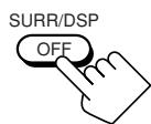
From the remote control
3D HEADPHONE Mode
You can also enjoy the Surround modes through the headphones.
If you press SURROUND when the front speakers 1 and 2 are both deactivated, 3D HEADPHONE mode is activated without respect to the type of software played back.
The DSP and HEADPHONE indicators also light up.
This unit provides a variety of DSP (Digital Signal Processor) modes. The stored basic settings and adjustments performed on the Setup and Adjustment Menus (see pages 35 to 50) are applied.
- The following operations are only possible when the receiver is ready for Zone 1 operations, and are used only for the Zone 1 sources.
Reproducing the Sound Field
The sound heard in a concert hall, club, etc. consists of direct sound and indirect sound—early reflections and reflections from behind. Direct sounds reach the listener directly without any reflection. On the other hand, indirect sounds are delayed by the distances of the ceiling and walls. These direct sounds and indirect sounds are the most important elements of the acoustic surround effects.
The DSP modes can create these important elements, and give you a real "being there" feeling.
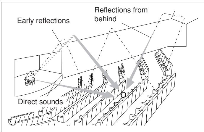
Introducing the DSP Modes
The DSP modes include the following modes
- DAP (Digital Acoustic Processor) modes (LARGE HALL 1, LARGE HALL 2, RECITAL HALL, OPERA HOUSE, CHURCH, LIVE CLUB, DANCE CLUB, PAVILION, LARGE THEATER, SMALL THEATER)
- ALL CH STEREO
STEREOFILM/MONO FILM
HEADPHONE Mode
You can also enjoy the DSP effect (except All Channel Stereo mode) through the headphones.
If you press DSP when the front speakers 1 and 2 are both deactivated, HEADPHONE mode is activated without respect to the type of software played back.
The DSP and HEADPHONE indicators also light up.
To use the DSP modes, press DSP so that the DSP modes change as follows.
The DSP indicator also lights up on the display.
LARGE HALL 1 LARGE HALL 2 RECITAL HALL
OPERA HOUSE CHURCH LIVE CLUB
DANCE CLUB PAVILION ALL CH STEREO
LARGE THEATER SMALL THEATER
→STEREO FILM → MONO FILM →
(Back to the beginning)
:Suitable for audio sources
:Suitable for videosources
DAP modes
You can use the following DAP modes in order to reproduce a more acoustic sound field in your listening room.
| LARGE HALL 1 : Reproduces the spatial feeling of a large shoebox-shaped hall designed primarily for classical concerts. (Its seating capacity is about 2000.) | |
| LARGE HALL 2 : Reproduces the spatial feeling of a large vineyard-shaped hall designed primarily for classical concerts. (Its seating capacity is about 2000.) | |
| RECITAL HALL : Reproduces the spatial feeling of a small hall designed primarily for classical recitals. (Seating capacity is about 500.) | |
| OPERA HOUSE : Reproduces the spatial feeling of an opera house with a high ceiling and multi-level seating layout. | |
| CHURCH : Reproduces the spatial feeling of a majestic church with a high ceiling. | |
| LIVE CLUB : Reproduces the spatial feeling of a live music club with a low ceiling. | |
| DANCE CLUB : Reproduces the spatial feeling of a rocking dance club. | |
| PAVILION : Reproduces the spatial feeling of an exhibition hall with a high ceiling. | |
| LARGE THEATER : Reproduces the spatial feeling of a large theater where the seating capacity is about 600. The built-in Dolby Pro Logic II decoder is activated for 2-channel software. (The ☐PLII indicator lights up.) | |
| SMALL THEATER : Reproduces the spatial feeling of a small theater where the seating capacity is about 300. The built-in Dolby Pro Logic II decoder is activated for 2-channel software. (The ☐PLII indicator lights up.) |
When using the DAP mode, the sounds come out of all the connected and activated speakers.
- If the surround speakers are deactivated, JVC's original 3D-PHONIC processing (which has been developed to create the surround effect through the front speakers only) is used.
The 3D-PHONIC indicator lights up on the display.
Continued on the next page
All Channel Stereo mode
This mode can reproduce a larger stereo sound field using all the connected (and activated) speakers. This mode cannot be used without activating the surround speakers.
- If headphones are connected or if the front speakers are deactivated, "ALL CH STEREO" cannot be selected.
- The settings on the EFFECT ADJUST submenu are not valid for "ALL CH STEREO."
Stereo Film and Monaural Film modes
In order to reproduce a more acoustic sound field in your listening room while viewing stereo sound or monaural sound video software (analog and 2-channel digital signals), you can use these modes. The surround effect will be added, and the sound localization of actor's words will be improved. This mode cannot be used when the source is "DVD MULTI" or "EXT 7.1CH" and when multichannel digital signals are coming in.
STEREO FILM : To play back stereo video software
MONO FILM : To play back monaural video software
When "STEREO FILM" or "MONO FILM" is used, sounds come out of all the connected (and activated) speakers.
- If incoming signals changes from 2-channel digital signal to another digital signal type, "STEREO FILM" or "MONO FILM" is canceled and an appropriate Surround mode is activated.
Activating the DSP Modes
Perform the basic settings and adjustments using the Setup and Adjustment Menus first (see pages 35 to 50).
Activating one of the DSP modes for a source automatically recalls the memorized settings and adjustments.
IMPORTANT:
Check to see if the following before or while using the buttons and controls.
For the Zone 1 operations:
The ZONE 1 ON/OFF lamp on the unit is lit.
- When using the unit:
"ZONE 2" is not shown in the main display.
-Press DOOR DOWN to use the buttons inside the front door.
To close the front door, press DOOR UP.
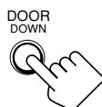
- When using the remote control:
- Set the ZONE 1/ZONE 2 (LEARN/TRANSMIT) selector to “ZONE 1.”
- Check the indication shown on the remote's display when you press a button—this indicates the remote control operation mode together with multi-room operation mode (either ZONE 1 or ZONE 2) for a while.
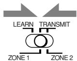
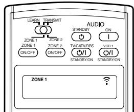
Ex. When you press DSP with ZONE 1/ZONE 2 (LEARN/TRANSMIT) selector set to "ZONE 1."
- Select and play any sound source.
2. Press DSP repeatedly until the DSP mode you want appears on the display.
Each time you press the button, the DSP modes change as follows:
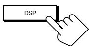
On the unit (inside the front door)
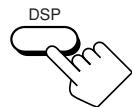
From the remote control
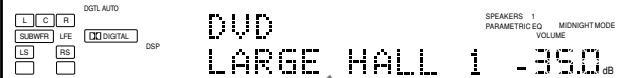
LARGE HALL 1 LARGE HALL 2 RECENTAL HALL
OPERA HOUSE CHURCH LIVE CLUB
DANCE CLUB PAVILION ALL CH STEREO
LARGE THEATER SMALL THEATER
→STEREO FILM → MONO FILM
(Back to the beginning)
- When multi-channel signals come in, you cannot select "STEREO FILM" and "MONO FILM."
Notes:
- When the surround speakers are deactivated, the 3D-PHONIC processing is applied to the DSP modes except "ALL CH STEREO" (the 3D-PHONIC indicator also lights up).
- If the Surround/THX mode is in use, it will be canceled when you turn on the DSP mode.
To adjust the DSP effects
Using the 10 keys on the remote control, you can adjust the level of the overall effect and the liveness (except for "ALL CH STEREO").
- Once you adjust the levels using the following procedure, the adjustments you have done on the Adjustment Menu will be also changed. (It is recommended to adjust the DSP effects using the Adjustment Menu since you can adjust other elements as well.)
1. Press SOUND.
The 10 keys are activated for sound adjustments.
2. Press EFFECT repeatedly to adjust the level of the overall effect (1 to 5).
- Press LIVENESS repeatedly to adjust the liveness (1 to 5).
To cancel the DSP modes
Press SURR/DSP OFF.
"SURROUND OFF" appears on the display.
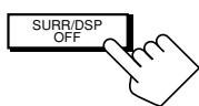
On the unit (inside the front door)
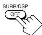
From the remote control
- When a pair of headphones is connected or when the front speakers are deactivated, "HEADPHONE" will appear.

Using the Analog Multi-channelPlayback Mode
This receiver provides the DVD MULTI and EXT 7.1CH playback modes for reproducing the analog discrete output mode of the DVD player or another component such as a digital decoder. Before using these playback modes, refer also to the manual supplied for those components.
- The following operations are only possible when the receiver is ready for Zone 1 operations, and are used only for the Zone 1 sources—"DVD MULTI" and "EXT 7.1CH."
Activating the Analog Multi-channelPlayback Modes
Perform the basic settings and adjustments using the Setup and Adjustment Menus first (see pages 35 to 50).
Activating DVD MULTI or EXT 7.1CH playback mode automatically recalls the memorized settings and adjustments.
- You also need to set the target component to the analog discrete output mode.
IMPORTANT:
Check following before or while using the buttons and controls.
For Zone 1 operations:
The ZONE 1 ON/OFF lamp on the unit is lit.
- When using the unit:
"ZONE 2" is not shown in the main display.
-Press DOOR DOWN to use the buttons inside the front door.
To close the front door, press DOOR UP.

- When using the remote control:
- Set the ZONE 1/ZONE 2 (LEARN/TRANSMIT) selector to “ZONE 1.”
- Check the indication shown on the remote's display when you press a button on the remote control—this indicates the remote control operation mode together with multi-room operation mode (either ZONE 1 or ZONE 2) for a while.
Ex. When you press DVD MULTI with ZONE 1/ZONE 2 (LEARN/TRANSMIT) selector set to “ZONE 1.”
1. Press DVD MULTI or EXT 7.1 CH.
On the unit (inside the front door)
From the remote control
Note:
To view the pictures through a component connected to the EXT 7.1CH IN jacks, you need to follow one of the methods explained on page 12.
2. Select the analog discrete output mode on the connected component, and start playback.
- Refer to the manual supplied with the connected component.
3. Apply the THX mode or the DSP mode if necessary.
- Press THX to apply the THX mode.
Each time you press the button, "THX U2 CINEMA" or "THX MUSIC" will be activated.
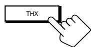
On the unit (inside the front door)

From the remote control
Note:
You cannot apply the THX mode in the following cases:
- When Analog Direct is turned on,
- When the Zone 2 speakers are activated, or
-
When the surround back speakers are deactivated or only one surround back speaker is used.
-
Press DSP to apply one of the DSP modes (except "STEREO FILM" and "MONO FILM").
Each time you press the button, the DSP modes change in sequence (see page 58 for details).
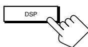
On the unit (inside the front door)
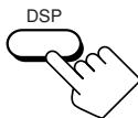
From the remote control
To adjust the speaker output level using the remote control, see page 56.
To cancel the THX and DSP modes
Press SURR/DSP OFF.
"DSP OFF" appears on the display.
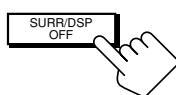
On the unit (inside the front door)
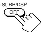
From the remote control
The COMPU LINK remote control system allows you to operate JVC audio components through this receiver.
To use this remote control system, you need to connect JVC audio components through the COMPU LINK (SYNCHRO) jacks (see below) in addition to the connections using cables with RCA pin plugs (see page 11).
- Make sure that the AC power cords of these components are unplugged before connection. Plug the AC power cords only after all connections are complete.
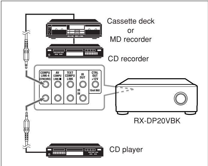
IMPORTANT:
Check the following before or while using the buttons and controls.
For Zone 1 operations:
The ZONE 1 ON/OFF lamp on the unit is lit.
For Zone 2 operations:
The ZONE 2 ON/OFF lamp on the unit is lit.
- When using the unit:
- For the Zone 1 operations: "ZONE 2" is not shown in the main display.
- For the Zone 2 operations: "ZONE 2" is shown in the main display.
- Press DOOR DOWN to use the buttons inside the front door.
To close the front door, press DOOR UP.

- When using the remote control:
When operating the receiver using the remote control, the display on the unit always shows the Zone 1 source information though you are operating it for the Zone 2 source.
- Set the ZONE 1/ZONE 2 (LEARN/TRANSMIT) selector to “ZONE 1” or “ZONE 2” correctly.
- Check the indication shown on the remote's display when you press a button—this indicates the remote control operation mode together with multi-room operation mode (either ZONE 1 or ZONE 2) for a while.

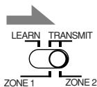
Notes:
- There are four versions of COMPU LINK remote control system. This receiver is equipped with the fourth version—COMPU LINK-4. This version is created by adding systematic operations with the CD recorder to the previous version—COMPU LINK-3.
- If your audio component has two COMPU LINK jacks, you can use either one. If it has only one COMPU LINK jack, connect it so that it is the last item in the series of components. (For example, the CD recorder or CD player on the left column.)
- To operate the cassette deck or MD recorder using the COMPU LINK remote control system, set the source name correctly. (See page 27.)
Refer also to the manuals supplied for your audio components.
This remote control system allows you to use the four functions listed below.
Remote Control through the Remote Sensor on the Receiver
You can control the connected audio components through the receiver using this remote control. For details, see pages 71 and 72.
Automatic Source Selection
- When you press the play (▶) button on a connected component or on its own remote control, the receiver automatically turns on and changes the Zone 1 source to the component.

Ex. When you operate the CD player
- If the receiver is already turned on with the ZONE 2 ON/OFF lamp on the unit lit and the source name for Zone 2 appears on the display, the receiver changes the Zone 2 source to the component.
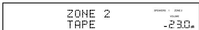
Ex. When you operate the cassette deck

- When you press PLAY on the remote control supplied for this receiver, the receiver automatically turns on and changes the Zone
source or Zone 2 source to the target component, depending on the ZONE 1/ZONE 2 (LEARN/TRANSMIT) selector setting on the remote control. - When you select a new source on the receiver or on the remote control supplied for this receiver either for Zone 1 or Zone 2, the newly selected component begins playing immediately, and the previously selected source continues playing without sound for a few seconds.
Note:
If the source changes from an analog source, for which Analog Direct (see page 27) is activated, to a digital source, muting time will be a little longer.
The period during which the receiver changes the source mechanically. No sound comes out during this period.
Automatic Power On/Off (Standby): only possible with the COMPU LINK-3 and COMPU LINK-4 connection
Automatic Power On:
- When you turn on the receiver by pressing / (STANDBY/ON) on the unit, or AUDIO | (ON) on the remote control with ZONE 1/ZONE 2 (LEARN/TRANSMIT) selector set to "ZONE 1":
OR
When you turn on the Zone 1 sound by pressing ZONE 1 ON/OFF while the receiver is turned on:
The ZONE 1 ON/OFF lamp lights up, and the source name for Zone 1 appears on the display, and one of the connected components will turn on automatically, depending on which component has been previously selected as the Zone 1 source.
- When you turn on the receiver by pressing AUDIO | (ON) on the remote control, with ZONE 1/ZONE 2 (LEARN/TRANSMIT) selector set to “ZONE 2”: OR
When you turn on the Zone 2 sound by pressing ZONE 2 ON/OFF while the receiver is turned on:
The ZONE 2 ON/OFF lamp lights up and one of the connected components will turn on automatically, depending on which component has been previously selected as the Zone 2 source.
Automatic Power Off (Standby):
- When you turn off the receiver by pressing /| (STANDBY/ON) on the unit, or AUDIO (STANDBY) on the remote control, the connected components will turn off (standby).
- When you turn off the Zone 1 sound by pressing ZONE 1 ON/OFF, the selected Zone 1 source component turns off (unless the same component is selected as the Zone 2 source). - If the ZONE 2 ON/OFF lamp is lit, the Zone 1 source will stop playing, but will not turn off.
- When you turn off the Zone 2 source by pressing ZONE 2 ON/OFF, the selected Zone 2 source component turns off (unless the same component is selected as the Zone 1 source). - If the ZONE 1 ON/OFF lamp is lit, the Zone 2 source will stop playing, but will not turn off.
Synchronized Recording
This operation is only possible when the receiver is ready for Zone 1 operations.
Synchronized recording means the cassette deck (or MD recorder) starts recording as soon as a CD begins playing.
To use synchronized recording, follow these steps:
- Put a tape in the cassette deck (or an MD in the MD recorder), and a disc in the CD player.
- Press the record (●) button and the pause (II) button on the cassette deck (or on MD recorder) at the same time.
This puts the cassette deck (or MD recorder) into recording pause.
If you do not press the record () button and pause (II) button at the same time, the synchronized recording feature will not operate.
- Press the play () button on the CD player.
The Zone 1 source changes on the receiver, and as soon as play starts, the cassette deck (or MD recorder) starts recording. When play ends, the cassette deck (or MD recorder) enters recording pause, and stops about 4 seconds later.
Notes:
-
During synchronized recording;
-
The selected Zone 1 source cannot be changed. (You can change the Zone 2 source.)
-
If the same source is selected both for Zone 1 and Zone 2, operating the Zone 2 source will affect the recording.
-
The COMPU LINK remote control system may not operate properly during synchronized recording;
-
If the power of any component is shut off.
- If the Zone 1 sound is turned off by pressing ZONE 1 ON/OFF. In this case, you must start recording again from the beginning.
The TEXT COMPU LINK remote control system has been developed to deal with the disc information recorded in the CD Text* and MDs. Using this information in the discs, you can operate the CD player or MD recorder with the TEXT COMPU LINK remote control system through the receiver.
CONNECTIONS
To use this remote control system, you need to connect the CD player and/or MD recorder you want to operate, following the procedures below.
- If you have already plugged your CD player, MD recorder, and this receiver into the AC outlets, unplug their AC power cords first.
- Connect your CD player, MD recorder, and this receiver as follows through the COMPU LINK jacks and TEXT COMPU LINK jacks.
1) COMPU LINK jacks: Use cables with monaural mini-plugs (not supplied with this receiver).
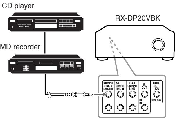
2) TEXT COMPU LINK jacks: Use cables with stereo mini-plugs (not supplied with this receiver).
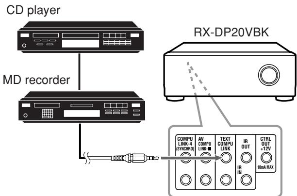
- Connect your CD player, MD recorder, and this receiver using the cables with RCA pin plugs (see page 11).
- Plug the AC power cords of these components above into the AC outlets.
- When turning on these components for the first time, turn on the connected components first, then turn on this receiver.
FUNCTIONS
This remote control system allows you to use the functions listed below.
Displaying the Disc Information on the TV screen
Disc information such as its performer and disc title (and track titles only when a CD Text is selected) is shown on the TV screen.
Disc Search: Only for CD Player
This remote control system allows you to search for discs by the performer, disc title, and music genre.
With this disc search, you can easily find the disc you want to play.
Disc Title Input
If your CD player or MD recorder has the disc memory function, you can input the following information about the normal audio CDs or MDs on the TV screen.
- For CDs: Performer, disc title, and music genre
- For MDs: Disc title and song titles
* What is a CD Text?
In a CD Text, some information about the disc (its disc title, performer, composer, arranger, etc.) is recorded.
Notes:
- If your audio component has two COMPU LINK jacks, you can use either one. If it has only one COMPU LINK jack, connect it so that it is the last item in the series of components. (For example, the CD player in the diagram on the left column.)
- If your audio component has two TEXT COMPU LINK jacks, you can use either one. If it has only one TEXT COMPU LINK jack, connect it so that it is the last item in the series of components. (For example, the CD player in the diagram on the left column.)
-
"TEXT COMPULINK SOURCE NOT CONNECTED" appears on the display in the following cases:
-
When the connections explained on the left are not correctly done.
- When you try to use the TEXT COMPU LINK function a few seconds after you turn on the connected equipment. This is not a malfunction of the units.
- Refer also to the manuals supplied with your CD player or MD recorder.
IMPORTANT:
If you turn on the receiver before turning on the other components after connecting the components, the TEXT COMPU LINK remote control system does not work correctly.
If this happens:
1. Turn off all the components including this receiver.
2. Turn on the connected components.
3. Turn on this receiver.
OPERATIONS
To use this remote control system, you need to connect the Zone 1 TV to the MONITOR OUT jack (see page 14) and the Zone 2 TV to the ZONE 2 MONITOR OUT jack (see page 19), and set the TV's input mode to the proper position to which the receiver is connected.
Make sure you have connected the CD player or MD recorder equipped with the TEXT COMPU LINK remote control system. If not, you cannot use the following functions.
IMPORTANT:
Check the following before or while using the buttons and controls.
-
When using the remote control:
-
Set the ZONE 1/ZONE 2 (LEARN/TRANSMIT) selector to “ZONE 1” or “ZONE 2” correctly.
- Check the indication shown on the remote's display when you press a button—this indicates the remote control operation mode together with multi-room operation mode (either ZONE 1 or ZONE 2) for a while.
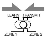
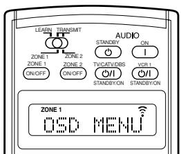
Ex. When you press TEXT DISPLAY with ZONE 1/ ZONE 2 (LEARN/ TRANSMIT) selector set to "ZONE 1."

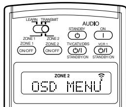
Ex. When you press TEXT DISPLAY with ZONE 1/ZONE 2 (LEARN/ TRANSMIT) selector set to "ZONE 2."

Text display operation buttons
■ Showing the Disc Information on the TV Screen (Either in Zone 1 or in Zone 2)
Press TEXT DISPLAY while "CD" or "MD" is selected as the source.
The Disc Information screen appears on the TV.
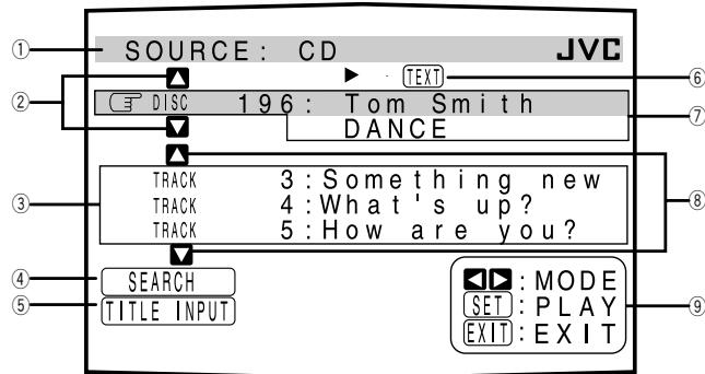
Disc Information screen
① Source name: CD or MD
② Select A or V , then press SET to change the disc.
③ Track numbers and track titles.
- When you move to a track number, you can change the track information by pressing < / > . Each time you press the button, track information alternates between its track title and its performer. (You can also start playing the track by pressing SET.)
④ Select this (move in front), then press SET to go to the DISC SEARCH screen (see page 65).
⑤ Select this (move in front), then press SET to go to the TITLE INPUT screen (see page 66).
This appears only when a CD Text is selected.
⑦ Disc information such as the disc title, performer, music genre, etc.
When this is selected ( in front), you can change the disc information by pressing < 1 / > . Each time you press the button, disc information (see "Note on ⑦") changes.
⑧ Select or , then press SET to change the track.
⑨ Usable buttons and their functions for the current selection. Indication here will change according to what is currently selected ( 3 in front) on the screen. See “Note on ⑨.”
Note on ⑦:
The following information will appear on the display:
- For CD Texts—Disc title, Performer, Genre, Song writer,Composer, Arranger, Message Only recorded information will be shown. If there is no data, "NO DATA" will appear.
- For MDs—Disc title
If there is no data, "NO DATA" will appear.
Note on ⑨:
For example, the SET button will be used to start play (PLAY), to go to the next screen (ENTER), and to determine the selection (ENTER).
To exit from the Disc information screen
Press EXIT.
Notes:
- The on-screen display will disappear in the following cases:
- if no operation is done for about 10 minutes.
if you do any operation other than explained in this section.
- To control the MD recorder using the TEXT COMPU LINK remote control system, you have to change the source name shown on the display from "TAPE" to "MD." (See page 27.)
- Some special characters and marks cannot be displayed correctly.
Searching for a Disc (Only for the CD player)
Search for a disc by its performer:
- Press TEXT DISPLAY while "CD" is selected as the source.
The Disc Information screen appears on the TV.
- Press / to move to "SEARCH," then press SET.
The DISC SEARCH screen appears.
- Press / to move to "PERFORMER," then press SET.
The PERFORMER SEARCH screen appears.
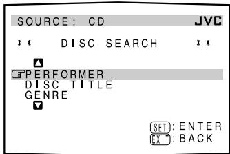
- Press / / / to move in front of the first character of the performer you want to search for, then press SET.
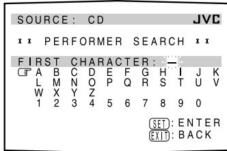
To correct an incorrect
entry, press / / / to move in front of the correct character, then press SET.
Note:
Symbols such as @, # or $ are not available for search.
- Press SET again.
Disc search starts, then the SEARCH RESULT screen, showing the performers, appears.
-
On the SEARCH RESULT screen, you can do the following:
-
Changing the indication of the disc information:
Press / to move to a searched disc, then press / . Each time you press / , the disc information alternates between its performer and its disc title. - Starting a disc play and going to the Disc Information screen (see page 64): Press / to move to a searched disc, then press SET.
- Showing unseen disc information (if more than 5 discs are listed as a result of the search): Press / until they appear.
- Going back to the PERFORMER SEARCH screen: Press EXIT.
Search for a disc by its disc title:
- Press TEXT DISPLAY while “CD” is selected as the source.
The Disc Information screen appears on the TV.
- Press / to move to "SEARCH," then press SET.
The DISC SEARCH screen appears.
- Press / to move to "DISC TITLE," then press SET.
The DISC TITLE SEARCH screen appears.

- Press / / / to move in front of the first character of the disc title you want to search for, then press SET.
To correct an incorrect
entry, press / / / to move 3 in front of the correct character, then press SET.
Note:
Symbols such as @, # or $ are not be available for search.
- Press SET again.
Disc search starts, then the SEARCH RESULT screen, showing the disc titles, appears.
-
On the SEARCH RESULT screen, you can do the following:
-
Changing the indication of the disc information: Press / to move to a searched disc, then press / . Each time you press / , the disc information alternates between its disc title and its performer.
- Starting a disc play and going to the Disc Information screen (see page 64): Press / to move to a searched disc, then press SET.
- Showing unseen disc information (if more than 5 discs are listed as a result of the search): Press / until they appear.
- Going back to the DISC TITLE SEARCH screen: Press EXIT.
Search for a disc by its genre:
- Press TEXT DISPLAY while “CD” is selected as the source.
The Disc Information screen appears on the TV.
- Press / to move 3 to "SEARCH," then press SET.
The DISC SEARCH screen appears.
- Press / to move to "GENRE," then press SET.
The GENRE SEARCH screen appears.
- Press / to move to the genre you want to search for, then press SET.
To show the unseen genres, press / until they appear. Disc search starts, then the
SEARCH RESULT screen, showing the disc titles, appears.
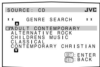
-
On the SEARCH RESULT screen, you can do the following:
-
Changing the indication of the disc information: Press / to move to a searched disc, then press
/ . Each time you press / , the disc information alternates between its disc title and its performer. - Starting a disc play and going to the Disc Information screen (see page 64): Press / to move to a searched disc, then press SET.
- Showing unseen disc information (if more than 5 discs are listed as a result of the search): Press / until they appear.
- Going back to the GENRE SEARCH screen: Press EXIT.
■ Entering the Disc Information
For a CD Player with disc memory function:
You can use the disc memory function through this receiver.
The disc information (its performer, disc title, and music genre) of normal audio CDs will be stored into the memory built in the CD player.
For the disc memory function, refer to the manual supplied with your CD player.
- The performer, disc title, and music genre information are usually recorded on a CD Text. However, if a CD Text has no genre information recorded on the disc itself, you can input its music genre yourself.
Note:
You can enter the TITLE INPUT screens for a CD Text and input its titles. However, you cannot store the titles you have input for a CD Text.
Example: Entering the following information for Disc 1 Performer: "MICHAEL"
Disc title: "MY FAVORITE"
- Press TEXT DISPLAY while "CD" is selected as the source.
The Disc Information screen appears on the TV.
- Press / to move to "TITLE INPUT," then press SET.
The TITLE INPUT: PERFORMER screen appears.
-
Press / / / to move in front of a character you want, then press SET to enter the character.
-
If the current CD is a CD Text, go to step 5 without entering the performer.
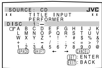
To use lower-case letters, press / / / to move to , then press SET.
To use upper-case letters again, press / / / to move to then press SET.
4. Repeat step 3 until you finish entering a performer name (up to 32 characters).
To insert a space, press / / / to move to SPACE, then press SET.
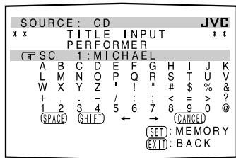
To correct an incorrect character:
1) Press / / / to move to or , then press SET until the incorrect character is selected.
2) Press / / / to move to , then press SET to erase the character.
3) Press / / / to move in front of the correct character, then press SET to enter the correct character.
5. Press / / / to move to "DISC 1: MICHAEL (in this example)," then press SET.
The TITLE INPUT: DISC TITLE screen appears.
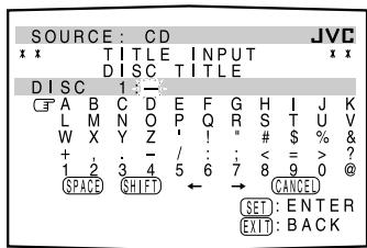
6. Enter the disc title, referring to steps 3 and 4.
- If the current CD is a CD Text, go to the next step without entering the disc title.
7. Press / / / to move to "DISC 1: MY FAVORITE (in this example)," then press SET.
The TITLE INPUT: DISC 1 GENRE screen appears.
8. Press / to move to the genre you want, then press SET.
The Disc Information screen appears again.
To show the unseen genres, press / until they appear.
For the MD recorder:
You can write the disc information (disc title and song titles) into the disc. You can only write the song title for the song currently selected.
- If you have the CD-MD combination deck, you can also enter the disc information (its performer, disc title, and its music genre) of normal audio CDs into the memory built in the CD-MD combination deck. (To do this, follow the procedure of "For a CD Player with disc memory function" on page 66.)
- If you change the disc or song title including more than 32 characters, the characters following the 32nd will be erased from the title.
1. Press TEXT DISPLAY while “MD” is selected as the source.
The Disc Information screen appears on the TV.
2. Press / to move to "TITLE INPUT," then press SET.
The DISC TITLE INPUT screen appears.

3. Enter the title, referring to steps 3 and 4 of "For a CD Player with disc memory function:" on pages 66 and 67.
- You can enter up to 32 characters for the disc title.
4. Press / / / to move to the disc title you have just entered, then press SET.
The disc title is stored into the memory, and the SONG TITLE INPUT screen for the currently selected song appears.
- You can enter a song title for the song currently selected.
5. Enter the song title, referring to steps 3 and 4 of "For a CD Player with disc memory function" on pages 66 and 67.
- You can enter up to 32 characters for the song title.
6. Press / / / to move to the song title you have just entered, then press SET.
The song title is stored into the memory, and the Disc Information screen appears again.
AV COMPU LINK Remote Control System
This receiver is equipped with the AV COMPU LINK-III. The AV COMPU LINK remote control system allows you to operate JVC video components (TV, VCR, and DVD player) through the receiver. To use this remote control system, you need to connect the video components you want to operate, following the procedure below.
Refer also to the manuals supplied with your video components.
-
If you have already plugged your VCR 1 (VCR connected to the VCR 1 jacks), DVD player, TV, and this receiver into the AC outlets, unplug their AC power cords first.
-
Connect the IR signal transmitter (supplied) to the IR OUT on the rear, and place it so that it is aimed at the remote sensor(s) on the target video component(s).
-
See "CONNECTIONS 1" below (and page 17 for details).
-
Connect your VCR 1, DVD player, TV, and this receiver as follows, using cables with monaural mini-plugs (not supplied).
See "CONNECTIONS 2" below.
- Connect the audio input/output jacks on VCR 1, DVD player, TV, and this receiver using the cables with RCA pin plug.
See pages 13 to 15.
-
Connect the video input/output jacks on VCR 1, DVD player, TV, and this receiver, using the cables with RCA pin plugs, with S-video plugs or with component video plugs.
-
See "CONNECTIONS 3" on the next page (and pages 13 to 15 for details).
-
Plug the AC power cords of the components into the AC outlets.
-
When turning on the TV for the first time after the AV COMPU LINK connection, turn the TV volume to the minimum using the TV volume control on the TV.
-
Turn on the other connected components first, then turn on this receiver.
-
When turning on the VCR 1, use the remote control supplied with this receiver—press VCR 1 (STANDBY/ON).
CONNECTIONS 1: IR Signal Transmitter Connection
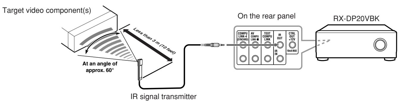
CONNECTIONS 2: AV COMPU LINK Connection
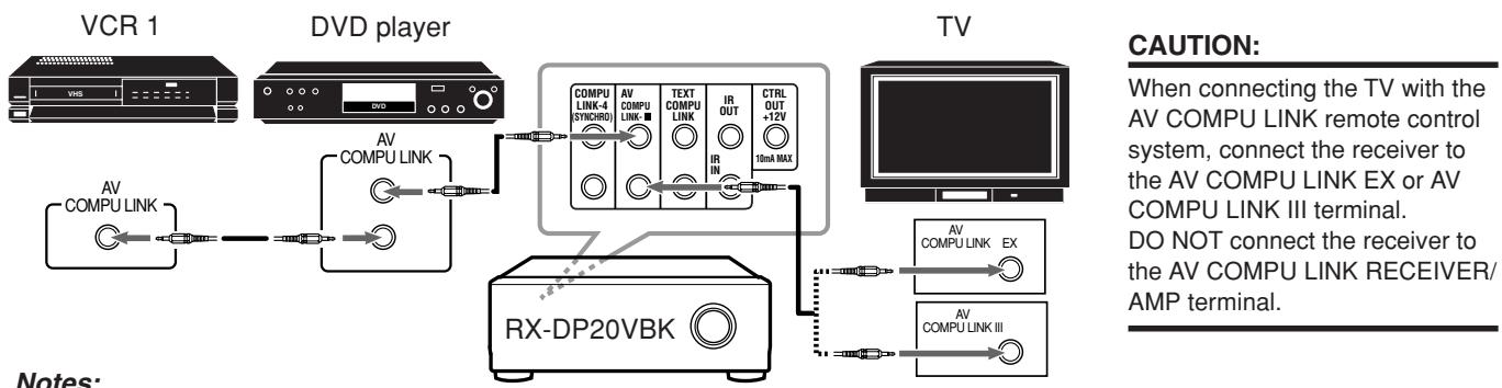
Notes:
- The AV COMPU LINK remote control system cannot control the DBS tuner connected to the TV SOUND/DBS IN jacks, and video components connected to the VIDEO and VCR 2 IN jacks on the receiver.
- When connecting only the VCR 1 or DVD player to this receiver, connect it directly to the receiver using a cable with the monaural mini-plugs.
- When connecting the receiver and the TV with AV COMPU LINK EX terminal by using the component video cables, you cannot use Automatic Selection of TV's Input Mode (see page 70).
CONNECTIONS 3: Video Cable Connection
This receiver is equipped with video signal conversion function (for details, see "IMPORTANT" on page 12). However, with the AV COMPU LINK remote control system, video conversion function cannot be used. So, connect the VCR and/or DVD player to the TV using only one of the following three ways:
- The video input terminal should be correctly preset (see “10 Setting the Video Input Terminals—VIDEO INPUT” on page 43); otherwise, the correct input for this receiver will not be selected on the TV.
| CASE 1 | When connecting the source equipment to the receiver through the S-video jacks, connect this receiver to the TV's Video Input 1 terminal using S-video cables. | |||
| Source Equipment | RX-DP20VBK | S-video cable | TV | |
| To Video Input 1 | ||||
| CASE 2 | When connecting the source equipment to the receiver through the composite video jacks, connect this receiver to the TV's Video Input 2 terminal (composite video input) using composite video cables. | |||
| Source Equipment | RX-DP20VBK | Composite video cable | TV | |
| To Video Input 2 | ||||
| CASE 3 | When connecting the source equipment to the receiver through the component video jacks, connect this receiver to the TV's Video Input 2 terminal (component video input) using component video cables. | |||
| Source Equipment | RX-DP20VBK | Component video cable | TV | |
| To Video Input 2 | ||||
The AV COMPU LINK remote control system allows you to use the five basic functions listed below.
Remote Control of the TV, DVD player, and VCR Using This Remote Control
IMPORTANT:
To operate the video components using the IR signal transmitter (supplied), place it so that it is aimed at the remote sensor(s) on the target video component(s).
- The IR signal transmitter can send signals at a distance of 3m (10 feet).
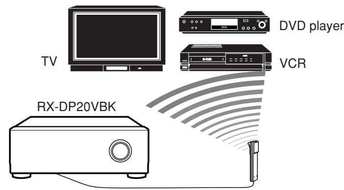
You can control the connected video components using this remote control. Aim the remote control at the remote sensor(s) on the target video component(s) or on the receiver directly. For details, see page 73.
One-Touch Video Play
- Simply by inserting a video cassette without its safety tab into the VCR 1 (the VCR connected to the VCR 1 jacks), you can watch the video playback without setting other switches manually. The receiver automatically turns on and changes the Zone 1 source to "VCR 1."
The Zone 1 TV automatically turns on and changes the input mode to the appropriate position so that you can view the playback picture.
When you insert a video cassette with its safety tab in place, press the play () button on the VCR 1 or on its remote control. Thus, you can get the same result.
-
If the receiver is already turned on with the ZONE 2 ON/OFF lamp on the unit is lit and the source name for Zone 2 appears on the display, the receiver changes the Zone 2 source to "VCR 1." (In this case, the Zone 2 TV will not turn on.)
-
When you press PLAY on the remote control supplied for this receiver for operating the VCR 1, the receiver automatically turns on and changes the Zone 1 source or Zone 2 source to "VCR 1"—depending on the ZONE 1/ZONE 2 (LEARN/ TRANSMIT) selector setting on the remote control.
-
For Zone 1 operations only: The Zone 1 TV automatically turns on and changes the input mode to the appropriate position so that you can view the picture.
One-Touch DVD Play
Simply by starting playback on the DVD player, you can enjoy the DVD playback without setting other switches manually.
When you press PLAY on the remote control supplied for this receiver for operating the DVD player, the receiver automatically turns on and changes the Zone 1 source or Zone 2 source, depending on the ZONE 1/ZONE 2 (LEARN/TRANSMIT) selector setting on the remote control, to the appropriate input—"DVD" or "DVD MULTI" as the Zone 1 source, and "DVD" as the Zone 2 source.
For Zone 1 operations: The Zone 1 TV automatically turns on and changes the input mode to the appropriate position so that you can view the playback picture.
- When the DVD player is connected through the analog input jacks on this receiver (and analog input is selected), the receiver automatically turns on and changes the source to "DVD" or "DVD MULTI."
- If the receiver is already turned on with the ZONE 2 ON/OFF lamp on the unit lit, and Zone 2 source name is shown on the display, the receiver changes the Zone 2 source to "DVD." In this case, the Zone 2 TV will not turn on.
- When the DVD player is connected through the digital input terminal on this receiver (and digital input is selected), the receiver automatically turns on and changes the Zone 1 source to "DVD."
- If the receiver is already turned on with the ZONE 2 ON/OFF lamp on the unit lit, and Zone 2 source name is shown on the display, the receiver changes the Zone 2 source to "DVD." (If no analog connection is made for the DVD player, no sound comes out of the Zone 2 front speakers).
Automatic Selection of TV's Input Mode (Only for Zone 1 Operations)
- When you select "TV" as the Zone 1 source to play on the receiver, the Zone 1 TV automatically changes the input mode to the TV tuner so that you can watch the Zone 1 TV.
- When you select "DVD," "DVD MULTI," "VCR 1," "VCR 2," "VIDEO" or "DBS" as the Zone 1 source to play on the receiver, the Zone 1 TV automatically changes the input mode to the appropriate position (either Video Input 1 or Video Input 2) so that you can view the playback picture.
Notes:
- When you select "TV" as the source on the receiver, you cannot see the menu on the TV screen since the AV COMPU LINK remote control system automatically changes the TV's input mode to the TV tuner. If you do not mind stopping listening to the TV sounds, you can then show the on-screen displays after changing the TV's input mode to the appropriate position (either Video Input 1 or Video Input 2) the receiver is connected to.
- This function does not work when you connect this receiver and the TV with the AV COMPU LINK EX terminal using the component video cables. To use this function, connect this receiver and the TV using the S-video or composite video cables.
Automatic Power On/Off (Standby)
Automatic Power On:
The Zone 1 TV, VCR 1 (the VCR connected to the VCR 1 jacks), and DVD player turn on and off along with the receiver.
- When you turn on the receiver by pressing /| (STANDBY/ON) on the front panel, or AUDIO | (ON) on the remote control with the ZONE 1/ZONE 2 (LEARN/TRANSMIT) selector set to "ZONE 1":
OR
When you turn on the Zone 1 sound by pressing ZONE 1 ON/OFF while the receiver is turned on:
The ZONE 1 ON/OFF lamp on the unit lights up and the source name for Zone 1 appears on the display, and;
- If the previously selected Zone 1 source is "VCR 1," the Zone 1 TV and VCR 1 will turn on automatically.
- If the previously selected Zone 1 source is "DVD" or "DVD MULTI," the Zone 1 TV and DVD player will turn on automatically.
- If the previously selected Zone 1 source is "VIDEO," "VCR 2," "TV" or "DBS," only the Zone 1 TV will turn on automatically.
- When you turn on the receiver by pressing AUDIO | (ON) on the remote control with the ZONE 1/ZONE 2 (LEARN/TRANSMIT) selector set to “ZONE 2”: OR
When you turn on the Zone 2 sound by pressing ZONE 2 ON/OFF while the receiver is turned on:
The ZONE 2 ON/OFF lamp lights up, and —
- If the previously selected Zone 2 source is "VCR 1," the VCR 1 will turn on automatically.
- If the previously selected Zone 2 source is "DVD," the DVD player will turn on automatically.
- If the previously selected Zone 2 source is "VIDEO," "VCR 2," or "DBS," nothing happens.
Automatic Power Off (Standby):
- When you turn off the receiver by pressing /| (STANDBY/ON) on the unit or AUDIO (STANDBY) on the remote control, the Zone 1 TV, VCR 1 and the DVD player will turn off (standby).
- When you turn off the Zone 1 sound by pressing ZONE 1 ON/OFF, the selected Zone 1 source component turns off (unless the same component is selected as the Zone 2 source), and the Zone 1 TV also turns off.
- If the ZONE 2 ON/OFF lamp is lit, nothing happens.
- When you turn off the Zone 2 sound by pressing ZONE 2 ON/OFF, the selected Zone 2 source component turns off (unless the same component is selected as the Zone 1 source). - If the ZONE 1 ON/OFF lamp is lit, nothing happens.
Note:
If you turn off the receiver by pressing /1 (STANDBY/ON) on the unit or AUDIO (STANDBY) on the remote control, or if you turn off the Zone 1 sound by pressing ZONE 1 ON/OFF while recording on the VCR 1, the VCR 1 will not turn off, but continue recording.
Operating JVC's Audio/Video Components
You can operate JVC's audio and video components with this receiver's remote control, since control signals for JVC components are preset in the remote control.
Operating Audio Components
IMPORTANT:
To operate JVC's audio components using this remote control:
- You need to connect JVC's audio components through the COMPU LINK (SYNCHRO) jacks (see page 61) in addition to the connections using cables with RCA pin plugs (see page 11).
- Aim the remote control directly at the remote sensor on the receiver.
- To operate a source with the remote control, the source must be selected using source selecting buttons on the remote control.
- To operate the cassette deck or MD recorder using the COMPU LINK remote control system, set the source name correctly. (See page 27.)
- Refer also to the manuals supplied with your components.
When using the remote control:
- Set ZONE 1/ZONE 2 (LEARN/TRANSMIT) selector to “ZONE 1” or “ZONE 2” correctly.
- Check the indication shown on the remote's display when you press a button—this indicates the remote control operation mode together with multi-room operation mode (either ZONE 1 or ZONE 2) for a while.
- The CONTROL button can change the remote control operation mode without changing the source.
Each time you press the button, the remote control operation mode changes in the sequence—VCR1 TAPE CDR CD DISC (back to the beginning).
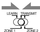
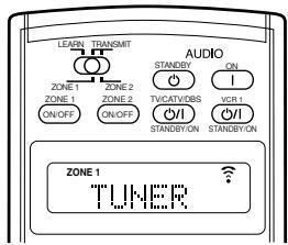
Ex. When you press FM/AM with ZONE 1/ZONE 2 (LEARN/TRANSMIT) selector set to “ZONE 1.”
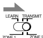
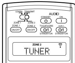
Ex. When you press FM/AM with ZONE 1/ZONE 2 (LEARN/TRANSMIT) selector set to "ZONE 2."
Tuner

You can always perform the following operations:
FM/AM
: Tunes in to the last station of the last selected band. Each time you press the button, the band alternates between FM and AM.
After pressing FM/AM, you can perform the following operations:
1-10, +10
: Selects a preset channel number directly. For channel number 5, press 5. For channel number 15, press +10 then 5. For channel number 20, press +10 then 10.
TUNING UP/DOWN
Tunes in to stations.
FM MODE
: Changes the FM reception mode.
Sound control section (Amplifier)
You can always perform the following operations:
THX
: Selects the THX modes.
SURROUND
: Selects the Surround modes
EX/ES/7.1
: Selects the 7.1-channel reproduction modes.
DSP
: Selects the DSP modes.
SURR/DSP OFF
: Deactivates the THX/Surround/DSP modes.
ANALOG DIRECT
:Turns on or off Analog Direct.
ANALOG/DIGITAL INPUT
: Selects the analog/digital inputs.
CC CONVERTER
:Turns on or off CC Converter.
After pressing SOUND, you can perform the following operations:
TEST
Turns on or off the test tone output.
FRONT·L then LEVEL +/-
: Adjusts the left front speaker channel output level.
FRONT·R then LEVEL +/-
: Adjusts the right front speaker channel output level.
SUBWFR then LEVEL + / -
: Adjusts the subwoofer output level.
CENTER then LEVEL + / -
: Adjusts the center speaker channel output level.
SURR•L then LEVEL +/-
: Adjusts the left surround speaker channel output level.
SURR·R then LEVEL +/-
: Adjusts the right surround speaker channel output level.
SURR BK-L then LEVEL + / -
: Adjusts the left surround back speaker channel output level.
SURR BK*R then LEVEL +/-
: Adjusts the right surround back channel speaker output level.
EFFECT
: Selects the effect level.
LIVENESS
: Selects the liveness.
Notes:
- After adjusting sounds, press the corresponding source selecting button to operate your target source by using the 10 keys; otherwise, the 10 keys cannot be used for operating your target source.
- When you press LEVEL + or LEVEL -, the corresponding speaker name appears on the remote's display.
CD player

After pressing CD, you can perform the following operations on the CD player:
PLAY :Starts playing.
: Returns to the beginning of the current (or previous) track.
: Skips to the beginning of the next track.
STOP : Stops playing.
PAUSE : Pauses playing. To release, press PLAY.
1 - 10, + 10 : Selects a track number directly.
For track number 5, press 5.
For track number 15, press +10 , then 5.
For track number 20, press +10 , then 10.
For track number 30, press +10 , +10 , then 10.
CD player-changer

After selecting "CD DISC" by pressing CONTROL repeatedly, you can perform the following operations on a CD player-changer:
PLAY :Starts playing.
: Returns to the beginning of the current (or previous) track.
: Skips to the beginning of the next track.
STOP : Stops playing.
PAUSE : Pauses playing. To release, press PLAY.
1-6,7/P : Selects the number of a disc installed in a CD player-changer.
After pressing CD, you can perform the following operations on the CD player-changer:
1 - 10, + 10 : Selects a track number directly.
For track number 5, press 5.
For track number 15, press +10 , then 5.
For track number 20, press +10 , then 10.
For track number 30, press +10 , +10 , then 10.
EXAMPLE:
-
Selecting disc number 4, track number 12, and starting playback.
-
Press CONTROL repeatedly until "CD DISC" appears on the remote's display, then press 4.
-
Press CD, then press +10 , 2.
If your CD changer is of 200-disc loading capability (except for XL-MC100 and XL-MC301)
You can do the following operations using the 10 keys after pressing CD:
-
Select a disc number.
-
Then select a track number (always enter two digits).
-
Start playback.
EXAMPLES:
- Selecting disc number 3, track number 2, and starting playback. Press 3, then, 0, 2, then PLAY.
- Selecting disc number 10, track number 5, and starting playback. Press 1, 0, then, 0, 5, then PLAY.
- Selecting disc number 105, track number 12, and starting playback. Press 1, 0, 5, then 1, 2 then PLAY.
Turntable

After pressing PHONO, you can perform the following operations on a turntable:
PLAY :Starts playing.
STOP : Stops operations.
CD recorder

After pressing CDR or selecting "CDR" by pressing CONTROL repeatedly, you can perform the following operations on a CD recorder:
PLAY :Starts playing.
: Returns to the beginning of the current (or previous) track.
: Skips to the beginning of the next track.
STOP : Stops playing.
PAUSE : Pauses playing. To release, press PLAY.
1-10, +10 : Selects a track number directly. For track number 5, press 5.
For track number 15, press +10 , then 5.
For track number 20, press +10 , then 10.
For track number 30, press +10 , +10 , then 10.
Note:
When you start recording on the CD recorder, use the buttons on the CD recorder itself or on the remote control supplied for it.
Cassette deck

After pressing TAPE/MD or selecting "TAPE" by pressing CONTROL repeatedly, you can perform the following operations on a cassette deck:
PLAY :Starts playing.
REW :Fast-winds the tape from right to left.
FF :Fast-winds the tape from left to right.
STOP : Stops operations.
PAUSE : Pauses playing. To release, press PLAY.
REC : Press this button together with the PLAY button to start recording (for Zone 1 operation only). Press this button together with the PAUSE button to enter recording pause (for Zone 1 operation only).
Note:
When connecting the cassette recorder to the TAPE/MD IN jacks, change the source name to "TAPE"-initial setting (see page 27).
MD recorder

After pressing TAPE/MD or selecting "TAPE*" by pressing CONTROL repeatedly, you can perform the following operations on the MD recorder:
PLAY :Starts playing.
: Returns to the beginning of the current (or previous) track.
: Skips to the beginning of the next track.
STOP : Stops playing.
PAUSE : Pauses playing. To release, press PLAY.
- REC : Press this button together with the PLAY button to start recording (for Zone 1 operation only). Press this button together with the PAUSE button to enter recording pause (for Zone 1 operation only).
Notes:
- When connecting an MD recorder to the TAPE/MD IN jacks, change the source name to "MD" (see page 27).
- Selecting "TAPE" will allow you to control the MD recorder.
Operating Video Components
IMPORTANT:
To operate JVC's video components using this remote control:
- You need to connect JVC's video components through the AV COMPU LINK jacks (see page 68) in addition to the connections using cables with RCA pin plugs (see pages 13 to 15).
-
Some JVC VCRs can accept two types of control signals—remote codes “A” and “B.” Before using this remote control, make sure that the remote control code of the VCR connected to the VCR 1 IN jacks is set to code “A.”
-
When another JVC VCR is connected to the VCR 2 IN and VIDEO jacks, set its remote control code to code "B." (This remote control cannot emit the control signals of code "B.")
-
To operate the video component(s) using the remote control: - Aim the remote control directly at the remote sensor on each component, not on the receiver.
- To operate the video component(s) using the RF signals emitted from this remote control, the IR signal transmitter and the RF rod antenna must be connected to this receiver.
- Place the IR signal transmitter so that it is aimed at the remote sensor(s) on the target video component(s).
- The RF signal-reachable distance may differ depending on the operating conditions and circumstances.
- The IR signal transmitter can send signals from a distance of 3m (10 feet).
When using the remote control:
- Set the ZONE 1/ZONE 2 (LEARN/TRANSMIT) selector to “ZONE 1” or “ZONE 2” correctly.
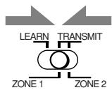

- Set the TV operation mode selector to "TV" or "CATV/DBS" properly.
To operate TV, set it to "TV."
- Check the indication shown on the remote's display when you press a button—this indicates the remote control operation mode together with multi-room operation mode (either ZONE 1 or ZONE 2) for a while.
- The CONTROL button can change the remote control operation mode without changing the source.
Each time you press the button, the remote control operation mode changes in the sequence—VCR1 TAPE CDR CD DISC (back to the beginning).
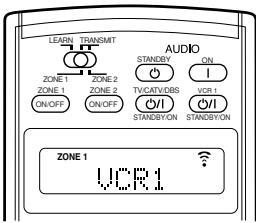
Ex. When you press VCR1 with ZONE 1/ZONE 2 (LEARN/TRANSMIT) selector set to "ZONE 1."
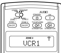
Ex. When you press VCR1 with ZONE 1/ZONE 2 (LEARN/TRANSMIT) selector set to "ZONE 2."
VCR (VCR connected to the VCR 1 jacks)

You can always perform the following operations:
VCR 1 (STANDBY/ON): Turns on or off the VCR.
After pressing VCR 1 or selecting "VCR1" by pressing CONTROL repeatedly, you can perform the following operations on the VCR:
1-9,0 : Selects the TV channels on the VCR.
PLAY :Startsplaying.
REW : Rewinds a tape.
FF :Fast-winds a tape.
STOP : Stops operations.
PAUSE : Pauses playing. To release, press PLAY.
- REC : Press this button together with the PLAY button to start recording (only for Zone 1 operations). Press this button together with the PAUSE button to enter recording pause (only for Zone 1 operations).
CHANNEL + / - : Changes the TV channels on the VCR.

DVD player
After pressing DVD (or DVD MULTI: only for Zone 1 operations), you can perform the following operations on the DVD player:
1-10, 0, +10 : Selects the DVD titles or the chapters.
PLAY :Startsplaying.
: Returns to the beginning of the current (or previous) chapter.
: Skips to the beginning of the next chapter.
STOP : Stops playing.
PAUSE : Stops playing temporarily. To release, press PLAY.
After pressing DVD MENU, these buttons can be used for the DVD menu operations.
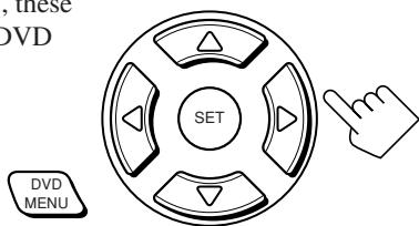
Note:
Refer also to the manual supplied for your DVD player (and the instruction supplied for the discs).
TV
You can always perform the following operations (with the TV operation mode selector set to "TV"):
TV/CATV/DBS (STANDBY/ON)
: Turns on or off the TV.
TV VOL + / - : Adjusts the volume.
TV/VIDEO : Sets the input mode (either TV or VIDEO).
After pressing TV/DBS (with the TV operation mode selector set to "TV"), you can perform the following operations on a TV:
CHANNEL + / - : Changes the channels.
1 - 9,0,100+ : Selects the channels.
RETURN : Alternates between the previously selected channel and the current channel.
Operating Other Manufacturers' Equipment
You can use this remote control supplied for operating other manufacturers' components, either by changing the preset signal codes or by using the learning function (see page 78).
IMPORTANT:
- To operate the other component(s) using the RF signals emitted from this remote control, the IR signal transmitter and the RF rod antenna must be connected to this receiver.
- Place the IR signal transmitter so that it is aimed at the remote sensor(s) on the target component(s).
- The RF signal-reachable distance may differ depending on the operating conditions and circumstances.
- The IR signal transmitter can send signals at a distance of 3m (10 feet).
When using the remote control:
- Set the ZONE 1/ZONE 2 (LEARN/TRANSMIT) selector to "ZONE 1" or "ZONE 2" correctly.
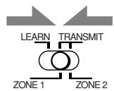
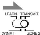
- Set the TV operation mode selector to "TV" or "CATV/DBS" correctly.
To operate TV, set it to "TV."
To operate the CATV converter or the DBS tuner, set it to "CATV/DBS." - Check the indication shown on the remote's display when you press a button—this indicates the remote control operation mode together with multi-room operation mode (either ZONE 1 or ZONE 2) for a while.
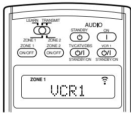
Ex. When you press VCR1
with ZONE 1/ZONE 2 (LEARN/TRANSMIT)
selector set to "ZONE 1."
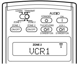
Ex. When you press VCR1
with ZONE 1/ZONE 2 (LEARN/TRANSMIT)
selector set to "ZONE 2."
CAUTION:
When replacing the batteries, finish changing them without delay; otherwise, preset manufacturers' codes will be reset.
Changing the Preset Signal Codes
By changing the transmittable signals from preset ones to the other manufacturers', you can operate the other manufacturer's components using this remote control.
- When operating the other manufacturers' components, refer also to the manuals supplied with them.
To change the transmittable signals for operating another manufacturer's TV
- Set the TV operation mode selector to "TV"
- Press and hold TV/CATV/DBS /1 (STANDBY/ON).
- Press TV/DBS.
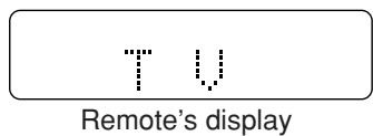
- Enter a manufacturer's code using buttons 1-9, and 0.
See page 76 to find the code.
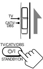


- Release TV/CATV/DBS / 1 (STANDBY/ON).
After setting the TV operation mode selector to "TV," you can perform the following operations on the TV:
TV/CATV/DBS (STANDBY/ON)
:Turns on or off the TV.
TV VOL + / - : Adjusts the volume.
TV/VIDEO : Sets the input mode (either TV orVIDEO).
After pressing TV/DBS (with the TV operation mode selector set to "TV"), you can perform the following operations on a TV:
CHANNEL + / - : Changes the channels.
1-10, 0, 100+ (+10) : Selects the channels.
Number button 10 will function as the ENTER button if your TV requires pressing ENTER after selecting a channel number.
Notes:
Refer to the manual supplied for your TV.
- All the buttons listed above may not be used for some TVs.
- If you cannot change the channels of some TVs by pressing number buttons, press CHANNEL +/- .
- Try to operate your TV by pressing TV/CATV/DBS / 1 (STANDBY/ON).
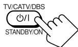
When your TV turns on or off, you have entered the correct code.
If more than one code is listed for your brand of TV, try each one until the correct one is entered.
To change the transmittable signals for operating another manufacturer's CATV converter and DBS tuner
- Set the TV operation mode selector to "CATV/DBS."
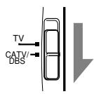
- Press and hold TV/CATV/DBS /1 (STANDBY/ON).
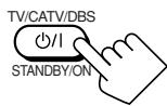
- Press TV/DBS.

Remote's display
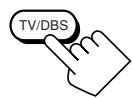
- Enter a manufacturer's code using buttons 1-9, and 0.
See page 77 to find the code.

- Release TV/CATV/DBS / (STANDBY/ON).
After setting the TV operation mode selector to "CATV/DBS," you can turn on and off the CATV converter or the DBS tuner:
TV/CATV/DBS (STANDBY/ON)
Turns on or off the CATV converter or DBS tuner.

After pressing TV/DBS (with TV operation mode selector set to "CATV/DBS"), you can perform the following operations on the CATV converter or on the DBS tuner:
CHANNEL + / -
: Changes the channels.
1-10, 0, 100+ (+10)
: Selects the channels.
Number button 10 will function as the ENTER button if your equipment requires pressing ENTER after selecting a channel number.
Note:
Refer to the manual supplied for your CATV convertor or DBS tuner.
- Try to operate your CATV converter or DBS tuner by pressing TV/CATV/DBS /1 (STANDBY/ON).
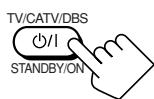
When your CATV converter or DBS tuner turns on or off, you have entered the correct code.
If more than one code is listed for your brand of CATV converter or DBS tuner, try each one until the correct one is entered.
Note:
You cannot preset the signals for both the CATV converter and DBS tuner at the same time.
To change the transmittable signals for operating another manufacturer's VCR
- Press and hold VCR 1 /1 (STANDBY/ON).
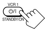
- Press VCR 1.

Remote's display
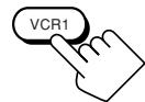
- Enter a manufacturer's code using buttons 1-9, and 0.
See page 77 to find the code.

- Release VCR 1 /| (STANDBY/ON).
The following button can be used for operating the VCR :
VCR 1 / (STANDBY/ON)
Turns on or off the VCR.

After pressing VCR 1, you can perform the following operations on the VCR:
1-10, 0, 100+ (+10)
: Selects the TV channels.
Number button 10 will function as the ENTER button if your VCR requires pressing ENTER after selecting a channel number.
PLAY
:Starts playback.
REW
: Rewinds a video tape.
FF
: Fast-winds a video tape.
STOP
: Stops operation.
PAUSE
: Pauses playing.
REC
: Press this button together with the PLAY button to start recording (only for Zone 1 operation).
Press this button together with the PAUSE button to enter recording pause (only for Zone 1 operation).
CHANNEL + / - : Changes the TV channels on the VCR.
Note:
Refer to the manual supplied for your VCR.
- Try to operate your VCR by pressing VCR 1 /1 (STANDBY/ON).
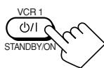
When your VCR turns on or off, you have entered the correct code.
If more than one code is listed for your brand of VCR, try each one until the correct one is entered.
To change the transmittable signals for operating another manufacturer's DVD player
- Press and hold AUDIO (STANDBY).
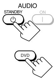
- Press DVD.

Remote's display
- Enter a manufacturer's code using buttons 1-9, and 0.
See page 77 to find the code.
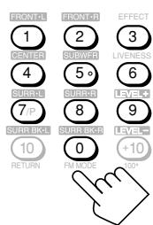
- Release AUDIO (STANDBY).
After pressing DVD (or DVD MULTI only for Zone 1 operation), you can perform the following operations on a DVD player:
1-9,0,+10 : Selects the titles or the chapters.
PLAY :Starts playing.
: Returns to the beginning of the current (or previous) chapter.
: Skips to the beginning of the next chapter.
STOP : Stops playing.
PAUSE : Stops playing temporarily. To release, press PLAY.
After pressing DVD MENU, these buttons can be used for the DVD menu operations.
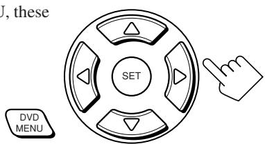
Note:
Refer also to the manual supplied for your DVD player (and the instructions supplied for the discs).
5. Try to operate your DVD player by pressing one of the above buttons.
DO NOT forget to turn on the DVD player before pressing one of the above buttons.
If more than one code is listed for your brand of DVD player, try each one until the correct one is entered.
To change the transmittable signals for operating another manufacturer's CD player
- Press and hold AUDIO !(ON).
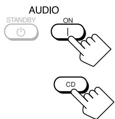
- Press CD.

Remote's display
3. Enter a manufacturer's code using buttons 1-9, and 0.
See page 77 to find the code.
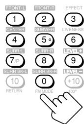
4. Release AUDIO | (ON).
After pressing CD, you can perform the following operations on a CD player:
1-9,0,+10 : Selects the tracks.
PLAY :Starts playing.
REW : Fast-reverses the tracks.
FF :Fast-forwards the tracks.
STOP : Stops playing.
PAUSE : Stops playing temporarily. To release, press PLAY.
Note:
Refer to the manual supplied for your CD player.
5. Try to operate your CD player by pressing one of the above buttons.
- DO NOT forget to turn on the CD player before pressing one of the above buttons.
If more than one code is listed for your brand of CD, try each one until the correct one is entered.
Manufactures' codes for TV
| Manufacturer | Codes |
| JVC | 00*, 13, 74 |
| Akai | 01, 02 |
| Blaupunkt | 03, 04 |
| Fisher | 01, 05 |
| Grundig | 03, 06, 07 |
| Hitachi | 08, 09, 10, 49, 78 |
| Irradio | 02 |
| ITT/Nokia | 11, 12 |
| Loewe | 06, 15, 16 |
| Magnavox | 08, 17, 49 |
| Matsushita | 86, 87 |
| Mets | 50, 51, 52, 53 |
| Mitsubishi | 08, 18, 19, 20 |
| Mivar | 21 |
| NEC | 83 |
| Nordmende | 22, 23 |
| Okano | 15 |
| Panasonic | 24, 25, 26, 27, 76 |
| Philips | 15, 17, 28, 75 |
| Pioneer | 85 |
| RCA/Proscan | 08, 24, 29, 30, 31, 48 |
| SABA | 32, 33, 68, 69, 70 |
| Samsung | 06, 08, 16, 34, 35, 49 |
| Sanyo | 01, 05, 81 |
| Schneider | 02, 15, 36 |
| Sharp | 37, 38, 77, 88 |
| Sony | 39, 80 |
| Telefunken | 40, 41, 42, 69 |
| Thomson | 71, 72 |
| Toshiba | 37, 43, 44, 79 |
| Zenith | 45, 46 |
*This figure is set to the remote control as the initial JVC code.
Manufactures' codes for DBS tune
| Manufacturer | Codes |
| JVC | 56, 57*, 67 |
| Amstrad | 43, 44, 45, 46, 47, 48, 49 |
| Blaupunkt | 30 |
| Echostar | 50, 51, 67 |
| General Instrument | 68 |
| Goldstar | 31 |
| Grundig | 32, 33 |
| Hirshmann | 48, 52, 53, 54, 55 |
| ITT/Nokia | 34 |
| Kathrein | 52, 58, 59, 60, 61, 62, 63 |
| NEC | 35, 36 |
| Orbitech | 48 |
| Philips | 37, 38 |
| RCA | 65 |
| Samsung | 39, 40 |
| Schwaiger | 61, 64 |
| Siemens | 41, 42 |
| Sony | 66 |
| Technisat | 48 |
*This figure is set to the remote control as the initial JVC code.
Manufactures' codes for CATV converter
| Manufacturer | Codes |
| General Instrument | 29 |
| Hamlin | 01, 02, 03, 04, 05 |
| Jerrold | 06, 07, 08, 09, 10, 11, 12, 13, 14 |
| Oak | 15, 16, 17 |
| Panasonic | 18, 19, 20 |
| Pioneer | 21, 22 |
| Scientific Atlanta | 23, 24, 25 |
| Tocom | 26 |
| Zenith | 27, 28 |
Manufactures' codes for VCR
| Manufacturer | Codes |
| JVC | 00*, 28, 29, 58, 83, 84 |
| Aiwa | 01, 02, 82 |
| Bell & Howell | 03 |
| Blaupunkt | 04, 05 |
| CGM | 06, 07 |
| Emerson | 08, 10, 11, 12, 64, 65 |
| Fisher | 03, 14, 15, 16, 17 |
| Funai | 01, 76 |
| GE | 18, 19, 20 |
| Goldstar | 07 |
| Goodmans | 13, 21 |
| Grundig | 06, 22 |
| Hitachi | 18, 23, 24, 25, 66, 74 |
| Loewe | 07, 21 |
| Magnavox | 04, 19, 24 |
| Matsushita | 77, 78 |
| Mitsubishi | 30, 31, 32, 33, 34, 35, 80, 81 |
| NEC | 26, 27 |
| Nokia | 03, 36 |
| Nordmende | 38 |
| Orion | 09 |
| Panasonic | 19, 24, 39, 40, 79 |
| Philips | 04, 19, 21, 24, 41, 42 |
| Phonola | 21 |
| Pioneer | 73 |
| RCA/Proscan | 04, 18, 19, 23, 24, 43, 44, 45 |
| SABA | 38, 46 |
| Samsung | 45, 47, 59, 61, 62, 63 |
| Sanyo | 03, 48, 49 |
| Sharp | 37, 50, 75 |
| Siemens | 03, 51 |
| Sony | 52, 53, 54, 68, 69, 70 |
| Telefunken | 55, 60 |
| Toshiba | 43, 44, 71, 72 |
| Zenith | 56, 57 |
*This figure is set to the remote control as the initial JVC code.
Manufactures' codes for DVD player
| Manufacturer | Codes |
| JVC | 00*, 02 |
| Denon | 01 |
| Panasonic | 03 |
| Philips | 13 |
| Pioneer | 04, 05, 06 |
| RCA | 07 |
| Samsung | 08 |
| Sony | 09 |
| Toshiba | 10 |
| Yamaha | 11, 12 |
*This figure is set to the remote control as the initial JVC code.
Manufactures' codes for CD player
| Manufacturer | Codes |
| JVC | 00*, 09 |
| Denon | 01, 02, 03 |
| Fisher | 04, 05 |
| Kenwood | 10, 11, 12, 13, 14 |
| Magnavox | 15, 16 |
| Marantz | 17 |
| Onkyo | 18, 19, 20, 21 |
| Panasonic | 22, 23, 24 |
| Philips | 25, 26, 27, 28, 29 |
| Pioneer | 30, 31 |
| RCA | 32, 33, 34 |
| Sanyo | 35 |
| Sharp | 36 |
| Sony | 53 |
| Teac | 37, 38, 39 |
| Technics | 40, 41, 42, 43, 45 |
| Yamaha | 46, 47, 48, 49, 50, 51, 52 |
*This figure is set to the remote control as the initial JVC code.
Note:
Manufacturers' codes are subject to change without notice. If they are changed, this remote control cannot operate the equipment.
Storing the Remote Signals Manually
You can store the signals into the learning buttons by sending the signals you want to store from another remote control.
This function is called "Learning Function."
The learning buttons
The highlighted buttons in the illustration below are the learning buttons you can store signals into.
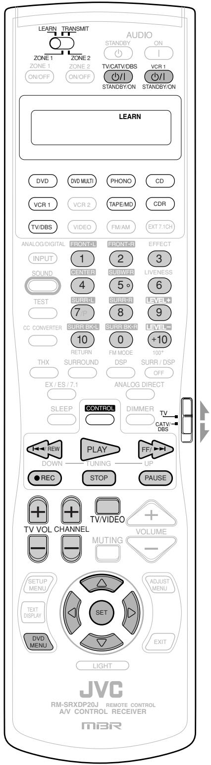
To store the signals
Before storing another manufacturer's signals, make sure that the manufacturer's remote control unit (hereafter called "target remote control") actually works.
- Set the LEARN/TRANSMIT (ZONE 1/ZONE 2) selector to "LEARN."
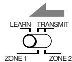
-
Place the two remote controls on a level surface with signal transmitting windows facing each other.
-
Leave a space of 5 to 10cm (2 to 4 inches) between the two remote controls; otherwise, storing may fail.
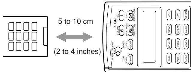
- Press one of the source selecting buttons (except VCR 2,VIDEO, FM/AM, and EXT 7.1CH).
The selected source name appears on the display.
- If possible, select the source corresponding to the target remote control's usage.
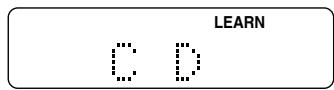
Ex. When you press CD.


Notes:
- Before pressing the TV/DBS button, set the TV operation mode selector to the desired position. You can store different signals into the 10 keys each for the TV, and the CATV converter or the DBS tuner.
- If you want to store signals for the CD changer, press CONTROL repeatedly until "CD DISC" appears on the remote's display.
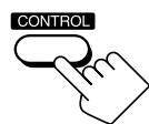
Continued on the next page
4. Press one of the learning buttons, to which you want to assign a signal from the target remote control.
The LEARN indicator starts flashing.
- If you have pressed DVD or DVD MULTI in step 3, you can store the signals into the following buttons:

- If you have pressed PHONO in step 3, you can store the signals into the following buttons:

- If you have pressed CD, or CONTROL to select "CD DISC," in step 3, you can store the signals into the following buttons: - You can store a different set of signals into the following buttons separately for "CD" and "CD DISC."
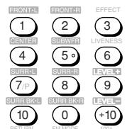

- If you have pressed TAPE/MD or CDR in step 3, you can store the signals into the following buttons:
- If you have pressed VCR 1 in step 3, you can store the signals into the following buttons:
-
If you have pressed TV/DBS in step 3, you can store the signals into the following buttons:
-
By setting the TV operation mode selector either to "TV" or "CATV/DBS," you can store a different set of signals into the following buttons.
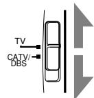

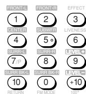
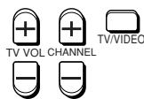
5. While the LEARN indicator is flashing, press the button on the target remote control.
The signal from the target remote control is sent to this remote control.

"LEARN OK" appears and the LEARN indicator stops flashing and remains lit. The target signal is now stored in the button selected in step 4.
Notes:
- If the LEARN indicator stops flashing before you press the button on the target remote control, repeat from step 4 again.
- If "ERROR" appears on the display, you have failed in storing the signal. Try again. However some signals do not match with this remote control even though this remote control can learn most infrared signals.
6. · Repeat steps 4 and 5 to store more signals in the same remote mode (source).
- Repeat steps 3 to 5 to store more signals in a different remote mode (source).
7. Set the LEARN/TRANSMIT (ZONE 1/ZONE 2) selector to "TRANSMIT (ZONE 1/ZONE 2)" to finish the storing procedure.
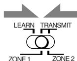
For the Zone 1 operations
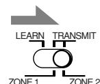
For the Zone 2 operations
Notes:
- The signals stored into this remote control from the target remote control deviate slightly from the original signals. Since some components will not accept these deviating signals, you may not be able to operate those components using this remote control even though the storing procedure has been successfully finished.
- When replacing the batteries, finish changing them without delay; otherwise, the stored signals are all erased.
To use the stored signals
When you want to use the stored signals, follow the procedure below.
IMPORTANT:
To operate the other component(s) using this remote control—
- Aim directly at the remote sensor(s) on the target component(s).
- This remote control can send signals at a distance of 7 m (23 feet).
OR
-
You can also use the IR signal transmitter connected to this receiver.
-
Place the IR signal transmitter so that it is aimed at the remote sensor(s) on the target component(s).
You can operate the other component(s) through the remote sensor on this receiver.
When using the remote control:
- Set the ZONE 1/ZONE 2 (LEARN/TRANSMIT) selector to "ZONE 1" or "ZONE 2" properly.
1. Set the LEARN/TRANSMIT (ZONE 1/ZONE 2) selector to "TRANSMIT (ZONE 1/ZONE 2)."
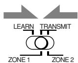
For the Zone 1 operations
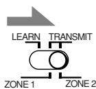
For the Zone 2 operations
2. Press one of the source selecting buttons (or CONTROL repeatedly) to select the desired remote control operation mode (source).
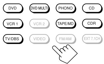
3. Press the desired button.
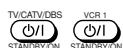
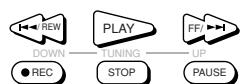

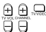
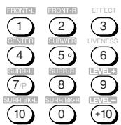

Notes:
- To operate the TV, CATV tuner, or DBS tuner, set the TV operation mode selector correctly.
- To use the following buttons, you can skip step 2 above.
- TV/CATV/DBS (STANDBY/ON), VCR 1 (STANDBY/ON), TV VOL +/-, TV/VIDEO, DVD MENU
To use the following buttons, press DVD MENU first. - SET, / / /
To erase the stored signals
After erasing the stored signals, preset signals are resumed and you can operate JVC's components again.
1. Set the LEARN/TRANSMIT (ZONE 1/ ZONE 2) selector to "LEARN."
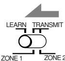
2. Press and hold EXIT, then press one of the source selecting buttons from which you want to erase the stored signals.
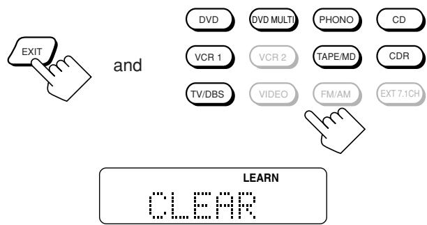
"CLEAR" appears on the display, and all the signals stored in the selected remote mode (source) are erased at the same time.
Notes:
- You cannot erase a signal assigned to a particular button only. Storing a new signal to a particular button erases the previously stored signal.
- To erase the stored signals for "CD DISC," first press CONTROL to select "CD DISC," then press CONTROL again while holding EXIT this time.
3. Set the LEARN/TRANSMIT (ZONE 1/ZONE 2) selector to "TRANSMIT (ZONE 1/ZONE 2)" to finish the erasing procedure.

For the Zone 1 operations
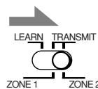
For the Zone 2 operations
Use this chart to help you solve daily operational problems. If there is any problem you cannot solve, contact your JVC service center.
| PROBLEM | POSSIBLE CAUSE | SOLUTION | |
| Multi-room operations (Zone1/Zone2) | The buttons and controls on the front panel do not work. | The multi-room function is not set correctly. | Press ZONE 1 ON/OFF for Zone 1 operations. Press ZONE 2 ON/OFF and ZONE 2 CONTROL for Zone 2 operations. |
| No sound from the speakers in Zone 1. | Speaker signal cables are not connected properly. | Check speaker wiring and reconnect if necessary. (See pages 8 to 10.) | |
| The SPEAKERS 1 and SPEAKERS 2 buttons are not set correctly. | Press SPEAKERS 1 and SPEAKERS 2 correctly. (See page 25.) | ||
| Incorrect source is selected for the Zone 1. | Select the correct source for the Zone 1. | ||
| Muting is activated for the Zone 1 source. | Press MUTING to cancel the mute. (See page 26.) | ||
| Incorrect input mode (analog or digital) is selected. | Select the correct input mode (analog or digital). (See page 25.) | ||
| Connections are incorrect. | Check connections. For analog connections, see pages 11 to 15. For digital connections, see pages 12 and 16. | ||
| No sound from the front speakers in Zone 2. | Speaker signal cables are not connected properly. | Check speaker connection and reconnect if necessary. (See page 19.) | |
| Zone 1/2 setting for the speakers connected to the FRONT 2/ZONE 2 SPEAKERS terminals are not set correctly. | Set the Zone 1/2 setting for the speakers correctly to use them as the Zone 2 front speakers. (See page 44.) | ||
| Amplifier connected to the ZONE 2 PREOUT is not turned on. | Turn on the amplifier. | ||
| Incorrect source is selected for Zone 2. | Select the correct Zone 2 source. | ||
| Muting is activated for the Zone 2 source. | Press MUTING to cancel the mute. (See page 32.) | ||
| Connections are incorrect. | Make analog connections for Zone 2. For analog connections, see pages 11 to 15. | ||
| The ZONE 2 (SPEAKERS 2) button does not work. | The speakers connected to the FRONT 2/ZONE 2 SPEAKERS are preset for Zone 1 usage. | Set them for Zone 2 usage. (See page 44.) | |
| CD tracks are skipped, tape is rewound, or radio station is changed unintentionally. | When the same source is selected both for Zone 1 and Zone 2, the source in one zone affects the source in the other zone. | This is normal, not a malfunction of the unit. Selecting different sources for Zone 1 and Zone 2 will avoid these troubles. | |
| The receiver does not work correctly as you operate it. | Zone 1 and Zone 2 operations are done at the same time. | If this happens, perform the same operation again. | |
| “TURN ON ZONE1 OR ZONE2” appears on the display. | The receiver is turned on with the Zone 1 and Zone 2 sounds deactivated. | Press ZONE 1 ON/OFF for Zone 1 operations. Press ZONE 2 ON/OFF for Zone 2 operations. | |
| Surround/THX | “EXES7.1 OFF” appears on the display, and 7.1-channel reproduction mode cannot be used for Zone 1 sources. | The “SPEAKER 2” setting is set to “ZONE 2 SPK” (and activated) on the ZONE 2/SPEAKER 2 submenu. | To use the 7.1-channel reproduction mode, set the “SPEAKER 2” setting to “SPEAKER 2,” then activate the surround back speaker(s). |
| “NO SURRBACK” appears on the display when you have tried to use 7.1-channel reproduction mode. | The “SPEAKER 2” setting is set to “BI-AMP OUT” on the ZONE 2/SPEAKER 2 submenu. | To use the 7.1-channel reproduction mode, set the “SPEAKER 2” setting to “SPEAKER 2,” then activate the surround back speaker(s). | |
| The “SURR BACK SP” setting is set to “NONE.” | Select “LARGE” or “SMALL” for the “SURR BACK SP.” | ||
| 7.1-channel reproduction mode cannot be used for Zone 1 sources. | The speakers connected to the FRONT 2/ZONE 2 SPEAKERS terminals are activated. | Deactivate the Zone 2 front speakers, then activate the surround back speakers. | |
| Expected surround effect cannot be obtained. | Speakers are deactivated on the SPEAKER SETTING submenu. | Activate all connected speakers correctly. (See “How to use the speaker and signal indicators” on page 24.) | |
| PROBLEM | POSSIBLE CAUSE | SOLUTION | |
| Continuous hissing or buzzing during FM reception. | Incoming signal is too weak. | Connect an outdoor FM antenna or contact your dealer. (See page 7.) | |
| The station is too far away. | Select a new station. | ||
| An incorrect antenna is used. | Check with your dealer to be sure you have the correct antenna. | ||
| Antennas are not connected properly. | Check connections. (See page 7.) | ||
| Occasional cracking noise during FM reception. | Ignition noise from automobiles. | Move the antenna farther from automobile traffic. | |
| Noise is heard during record playing. | A ground cable of the turntable is not connected to the screw marked (½). | Connect it to the screw marked (½). | |
| Howling during record playing. | Your turntable is too close to speakers. | Move speakers away from the turntable. | |
| "OVERLOAD" starts flashing on the display. | Speakers are overloaded because of high volume either in Zone 1 or in Zone 2. | 1. Press Ⓞ/I (STANDBY/ON) on the front panel to turn off the receiver. 2. Stop the playback source. 3. Turn on the receiver again, and adjust the volume. | |
| Speakers are overloaded because of a short circuit of the speaker terminals. | Press Ⓞ/I (STANDBY/ON) on the front panel to turn off the receiver, check the speaker wiring, then press it again to turn on the receiver again. If "OVERLOAD" does not disappear despite speaker wiring not being short-circuited, consult your dealer. | ||
| The STANDBY lamp goes off after turning on the power, but soon the receiver turns off again (into standby mode). | Very high voltage or very low voltage is applied to the unit, or built-in power amplifier becomes out of order. | Press Ⓞ/I (STANDBY/ON) on the front panel to turn off the receiver. After unplugging the AC power cord, consult your dealer. | |
| Remote control does not work. | The ZONE 1/ZONE 2 selector is not set correctly. | Set the selector correctly either to "ZONE 1" or to "ZONE 2." | |
| The TV operation mode selector is not set correctly. | Set the selector correctly either to "TV" or to "CATV/DBS." | ||
| The BAND 1/2 selectors on the rear and on the remote control are set to a different band. | Set both the BAND 1/2 selectors to the same band. (See page 17.) | ||
| RF communication between the receiver and the remote control is interrupted from outside. | Consult your dealer. | ||
| Batteries are weak. | Replace batteries. (See page 18.) | ||
| Remote control does not work properly. | Incorrect remote control operation mode is selected. | Select the correct remote control operation mode. (See pages 71 to 80.) | |
Amplifier
Output Power
At Stereo operation (Analog Direct On):
Front channels:
120 W per channel, min. RMS, driven into 8 Ω, 20 Hz to 20 kHz with no more than 0.02% total harmonic distortion.
120 W per channel, min. RMS, driven into 4 , 20Hz to 20kHz with no more than 0.07% total harmonic distortion.
Front channels:
120 W per channel, min. RMS, driven into 8 Ω, 20 Hz to 20 kHz with no more than 0.02% total harmonic distortion.
Center channel:
120 W, min. RMS, driven into 8 Ω, 20 Hz to 20 kHz with no more than 0.02% total harmonic distortion.
Surround channels:
120 W per channel, min. RMS, driven into 8 Ω, 20 Hz to 20 kHz with no more than 0.02% total harmonic distortion.
Surround back channels:
120 W per channel, min. RMS, driven into 8 Ω, 20 Hz to 20 kHz with no more than 0.02% total harmonic distortion.
Audio
Audio Input Sensitivity/Impedance (1 kHz):
PHONO IN (MC): 0.25mV / 100
(MM): 2.5 mV / 47 k
CD IN, CDR IN, TAPE/MD IN, EXT 7.1CH IN:
200 mV/47 kΩ
DVD IN, VCR 1 IN, VCR 2 IN, TV SOUND/DBS IN, VIDEO:
200 mV/47 kΩ
Audio Input (DIGITAL IN)* :
Coaxial: 1(DVD), 2(CD), 3(TV/DBS):
Optical: 4(CDR), 5(MD), 6(VCR1):
0.5 V(p-p)/75 Ω
-21dBm to -15dBm (660nm± 30nm)
- Corresponding to Linear PCM, Dolby Digital, and DTS Digital Surround (with sampling frequency — 32 kHz, 44.1 kHz, 48 kHz)
Audio Output Level: ZONE 2 PREOUT:
200mV
PREOUT: 1 V
Recording Output Level:
TAPE/MD OUT, CDR OUT, VCR 1 OUT, VCR 2 OUT:
200mV
Digital output: Optical:
DIGITAL OUT
Signal wavelength:
660~nm
Output level:
-21 dBm to -15 dBm
Signal-to-Noise Ratio ('66 IHF/'78 IHF) (Analog Direct On):
PHONO IN (MC) :
(MM) :
60 dB/72 dB (at REC OUT)
72 dB/80 dB (at REC OUT)
CD IN, CDR IN, TAPE/MD IN, EXT 7.1CH IN:
92 dB/80 dB
DVD IN, VCR 1 IN, VCR 2 IN, TV SOUND/DBS IN, VIDEO:
92 dB/80 dB
Frequency Response (8 Ω):
PHONO IN (MC) :
(MM) :
20Hz to 20kHz (± 1 dB)
20Hz to 20kHz (± 1 dB)
CD IN, CDR IN, TAPE/MD IN, EXT 7.1CH IN:
10Hz to 100kHz(+1dB, - 3dB)
DVD IN, VCR 1 IN, VCR 2 IN, TV SOUND/DBS IN, VIDEO:
10Hz to 100kHz (+1dB, - 3dB)
RIAA Phono Equalization:
± 1.0 dB (20 Hz to 20 kHz)
Video
Video Input Sensitivity/Impedance:
Composite video:
DVD IN, VCR 1 IN, VCR 2 IN, TV SOUND/DBS IN, VIDEO:
S-video:
DVD IN, VCR 1 IN, VCR 2 IN, TV SOUND/DBS IN, VIDEO:
Component:
1 IN (DVD), 2 IN, 3 IN:
1 V(p-p)/75 Ω
(Y: luminance): 1V(p - p) / 75
(C: chrominance, burst): 0.286 V(p-p)/75 Ω
(Y: luminance): 1V(p - p) / 75
(P_B, P_R) : 0.7V(p - p) / 75
Video Output Level:
Composite video: VCR 1 OUT, VCR 2 OUT, MONITOR OUT:
S-video: VCR 1 OUT, VCR 2 OUT, MONITOR OUT:
Component:
MONITOR OUT:
1 V(p-p)/75 Ω
(Y: luminance): 1V(p - p) / 75
(C: chrominance, burst): 0.286 V(p-p)/75 Ω
(Y: luminance): 1V(p - p) / 75
(P_B, P_R) : 0.7 ~V(p-p) / 75
Synchronization:
Signal-to-Noise Ratio:
Negative
45 dB
FMtuner (IHF)
Tuning Range:
Monaural:
87.5 MHz to 108.0 MHz
Usable Sensitivity:
Monaural:
18.2 dBi (2.2 μV/75 s²)
Stereo: 38.2 dBf (22.3 V/75 Ω)
50 dB Quieting Sensitivity:
Signal-to-Noise Ratio (IHF-A weighted):
Monaural:
78 dB at 85 dBf
Stereo: 73 dB at 85 dBf
Total Harmonic Distortion:
Monaural:
0.2% at 1kHz
Stereo: 0.3% at 1kHz
Stereo Separation at REC OUT:
40 dB at 1 kHz
Alternate Channel Selectivity:
60 dB (±400 kHz)
Frequency Response:
30Hz to 15kHz(+0.5dB, - 3dB)
AMtuner
Tuning Range:
Loop antenna:
530kHz to 1710kHz
Usable Sensitivity:
400 V / m
Signal-to-Noise Ratio:
50 dB (100 mV/m)
General
Power Requirements:
AC 120V ,60Hz
Power Consumption:
580 W/690 VA (at operation)
2.7 watts (in standby mode)
Dimensions (W× H× D)
445mm× 177mm× 475mm
(17^9 / _16 in. x 7 in. x 18^3 / 4 in.)
Mass:
23.5kg (52 lbs)
Designs & specifications are subject to change without notice.
Prises DIGITAL IN (16)
Coaxiale: 1 (DVD), 2 (CD), 3 (TV/DBS)
- Optique: 4 (CDR), 5 (MD), 6 (VCR 1)
- Entrée: PHONO IN, CD IN, TAPE/MD IN, CDR IN TV SOUND/DBS IN, VCR 1 IN, VCR 2 IN, DVD IN (5.1 ch)
- Sortie: TAPE/MD OUT, CDR OUT VCR 1 OUT, VCR 2 OUT
TAPE/MD, CDR, TV/DBS,VIDEO, FM/AM, EXT 7.1CH
6 Touche ANALOG/DIGITAL INPUT (25, 71)
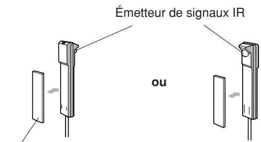
Ruban adhesif double-face
Verticalment: 60^

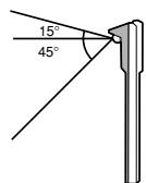
BOUNDARY GAIN COMPENSATION
COAX IN 1/2/3, OPT IN 4/5/6
DTS Digital Surround
DTS Extended Surround (DTS-ES)
:Demarrer la lecture.
:Demarrer la lecture.
STOP
:Demarrer la lecture.
REW
TV/CATV/DBS (STANDBY/ON)
| Fabricant | Codes |
| JVC | 00*, 13, 74 |
| Akai | 01, 02 |
| Blaupunkt | 03, 04 |
| Fisher | 01, 05 |
| Grundig | 03, 06, 07 |
| Hitachi | 08, 09, 10, 49, 78 |
| Irradio | 02 |
| ITT/Nokia | 11, 12 |
| Loewe | 06, 15, 16 |
| Magnavox | 08, 17, 49 |
| Matsushita | 86, 87 |
| Mets | 50, 51, 52, 53 |
| Mitsubishi | 08, 18, 19, 20 |
| Mivar | 21 |
| NEC | 83 |
| Nordmende | 22, 23 |
| Okano | 15 |
| Panasonic | 24, 25, 26, 27, 76 |
| Philips | 15, 17, 28, 75 |
| Pioneer | 85 |
| RCA/Proscan | 08, 24, 29, 30, 31, 48 |
| SABA | 32, 33, 68, 69, 70 |
| Samsung | 06, 08, 16, 34, 35, 49 |
| Sanyo | 01, 05, 81 |
| Schneider | 02, 15, 36 |
| Sharp | 37, 38, 77, 88 |
| Sony | 39, 80 |
| Telefunken | 40, 41, 42, 69 |
| Thomson | 71, 72 |
| Toshiba | 37, 43, 44, 79 |
| Zenith | 45, 46 |
| Fabricant | Codes |
| General Instrument | 29 |
| Hamlin | 01, 02, 03, 04, 05 |
| Jerrold | 06, 07, 08, 09, 10, 11, 12, 13, 14 |
| Oak | 15, 16, 17 |
| Panasonic | 18, 19, 20 |
| Pioneer | 21, 22 |
| Scientific Atlanta | 23, 24, 25 |
| Tocom | 26 |
| Zenith | 27, 28 |
| Fabricant | Codes |
| JVC | 00*, 28, 29, 58, 83, 84 |
| Aiwa | 01, 02, 82 |
| Bell & Howell | 03 |
| Blaupunkt | 04, 05 |
| CGM | 06, 07 |
| Emerson | 08, 10, 11, 12, 64, 65 |
| Fisher | 03, 14, 15, 16, 17 |
| Funai | 01, 76 |
| GE | 18, 19, 20 |
| Goldstar | 07 |
| Goodmans | 13, 21 |
| Grundig | 06, 22 |
| Hitachi | 18, 23, 24, 25, 66, 74 |
| Loewe | 07, 21 |
| Magnavox | 04, 19, 24 |
| Matsushita | 77, 78 |
| Mitsubishi | 30, 31, 32, 33, 34, 35, 80, 81 |
| NEC | 26, 27 |
| Nokia | 03, 36 |
| Nordmende | 38 |
| Orion | 09 |
| Panasonic | 19, 24, 39, 40, 79 |
| Philips | 04, 19, 21, 24, 41, 42 |
| Phonola | 21 |
| Pioneer | 73 |
| RCA/Proscan | 04, 18, 19, 23, 24, 43, 44, 45 |
| SABA | 38, 46 |
| Samsung | 45, 47, 59, 61, 62, 63 |
| Sanyo | 03, 48, 49 |
| Sharp | 37, 50, 75 |
| Siemens | 03, 51 |
| Sony | 52, 53, 54, 68, 69, 70 |
| Telefunken | 55, 60 |
| Toshiba | 43, 44, 71, 72 |
| Zenith | 56, 57 |
| Fabricant | Codes |
| JVC | 00*, 09 |
| Denon | 01, 02, 03 |
| Fisher | 04, 05 |
| Kenwood | 10, 11, 12, 13, 14 |
| Magnavox | 15, 16 |
| Marantz | 17 |
| Onkyo | 18, 19, 20, 21 |
| Panasonic | 22, 23, 24 |
| Philips | 25, 26, 27, 28, 29 |
| Pioneer | 30, 31 |
| RCA | 32, 33, 34 |
| Sanyo | 35 |
| Sharp | 36 |
| Sony | 53 |
| Teac | 37, 38, 39 |
| Technics | 40, 41, 42, 43, 45 |
| Yamaha | 46, 47, 48, 49, 50, 51, 52 |
CD IN, CDR IN, TAPE/MD IN, EXT 7.1CH IN:
200 mV/47 kΩ
DVD IN, VCR 1 IN, VCR 2 IN, TV SOUND/DBS IN, VIDEO:
200 mV/47 kΩ
TAPE/MD OUT, CDR OUT, VCR 1 OUT, VCR 2 OUT:
200mV
Sortie numérique:
Optique:
DIGITAL OUT
CD IN, CDR IN, TAPE/MD IN, EXT 7.1CH IN:
92 dB/80 dB
DVD IN, VCR 1 IN, VCR 2 IN, TV SOUND/DBS IN, VIDEO:
92 dB/80 dB
CD IN, CDR IN, TAPE/MD IN, EXT 7.1CH IN:
10Hz à 100kHz (+1dB, - 3dB)
DVD IN, VCR 1 IN, VCR 2 IN, TV SOUND/DBS IN, VIDEO:
10Hz à 100kHz(+1dB, - 3dB)
Égalisation Phono RIAA:
DVD IN, VCR 1 IN, VCR 2 IN, TV SOUND/DBS IN,VIDEO: 1V(c - c) / 75
S-video:
DVD IN, VCR 1 IN, VCR 2 IN, TV SOUND/DBS IN, VIDEO:
(Y: luminance): 1V(c - c) / 75
(C: chrominance, en salve): 0,286 V(c-c)/75 Ω
1 IN (DVD), 2 IN, 3 IN
(Y: luminance): 1V(c - c) / 75
(P_B / P_R) 0,7 V(c-c)/75 Ω
(Y: luminance): 1V(c - c) / 75
Composantes: MONITOR OUT
(C: chrominance, en salve): 0.286V(c - c) / 75
Synchronisation:
(Y: luminance): 1V(c - c) / 75