EBS-A700 - NAS ASUS - Free user manual and instructions
Find the device manual for free EBS-A700 ASUS in PDF.

User questions about EBS-A700 ASUS
0 question about this device. Answer the ones you know or ask your own.
Ask a new question about this device
Download the instructions for your NAS in PDF format for free! Find your manual EBS-A700 - ASUS and take your electronic device back in hand. On this page are published all the documents necessary for the use of your device. EBS-A700 by ASUS.
USER MANUAL EBS-A700 ASUS
(Industrial Computer)
User's Manual
natural_image
Exterior view of a white server or computer chassis unit (no visible text or labels)
natural_image
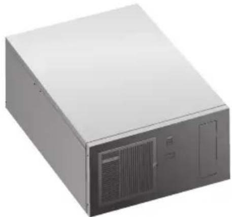
Exterior view of a gray server tower with ventilation slots and ventilation duct (no visible text or labels)EBS-A700
Applicable for products with P/N of 90AE01A
This equipment is not suitable for use in locations where children are likely to be present.
E22283
First Edition
August 2023
Copyright © 2023 ASUSTeK Computer Inc. All Rights Reserved.
No part of this manual, including the products and software described in it, may be reproduced, transmitted, transcribed, stored in a retrieval system, or translated into any language in any form or by any means, except documentation kept by the purchaser for backup purposes, without the express written permission of ASUSTeK Computer Inc. ("ASUS").
Product warranty or service will not be extended if: (1) the product is repaired, modified or altered, unless such repair, modification of alteration is authorized in writing by ASUS; or (2) the serial number of the product is defaced or missing.
ASUS PROVIDES THIS MANUAL "AS IS" WITHOUT WARRANTY OF ANY KIND, EITHER EXPRESS OR IMPLIED, INCLUDING BUT NOT LIMITED TO THE IMPLIED WARRANTIES OR CONDITIONS OF MERCHANTABILITY OR FITNESS FOR A PARTICULAR PURPOSE. IN NO EVENT SHALL ASUS, ITS DIRECTORS, OFFICERS, EMPLOYEES OR AGENTS BE LIABLE FOR ANY INDIRECT, SPECIAL, INCIDENTAL, OR CONSEQUENTIAL DAMAGES (INCLUDING DAMAGES FOR LOSS OF PROFITS, LOSS OF BUSINESS, LOSS OF USE OR DATA, INTERRUPTION OF BUSINESS AND THE LIKE), EVEN IF ASUS HAS BEEN ADVISED OF THE POSSIBILITY OF SUCH DAMAGES ARISING FROM ANY DEFECT OR ERROR IN THIS MANUAL OR PRODUCT.
SPECIFICATIONS AND INFORMATION CONTAINED IN THIS MANUAL ARE FURNISHED FOR INFORMATIONAL USE ONLY, AND ARE SUBJECT TO CHANGE AT ANY TIME WITHOUT NOTICE, AND SHOULD NOT BE CONSTRUED AS A COMMITMENT BY ASUS. ASUS ASSUMES NO RESPONSIBILITY OR LIABILITY FOR ANY ERRORS OR INACCURACIES THAT MAY APPEAR IN THIS MANUAL, INCLUDING THE PRODUCTS AND SOFTWARE DESCRIBED IN IT.
Products and corporate names appearing in this manual may or may not be registered trademarks or copyrights of their respective companies, and are used only for identification or explanation and to the owners' benefit, without intent to infringe.
Table of contents
Safety information....v
About this guide....vi
System package contents......viii
Chapter 1 System introduction
1.1 Welcome! 1-2
1.2 Brief introduction 1-2
1.3 Front panel 1-4
1.4 Rear panel.... 1-5
1.5 Internal components.... 1-8
1.6 Mounting the chassis.... 1-9
Chapter 2 Motherboard information
2.1 Motherboard layout 2-2
2.2 Central Processing Unit (CPU).... 2-4
2.3 System memory 2-4
2.4 Jumpers.... 2-5
2.5 Internal connectors.... 2-8
Chapter 3 BIOS setup
3.1 BIOS setup program.... 3-2
3.1.1 BIOS menu screen 3-3
3.2 Main menu.... 3-3
3.2.1 System Date [Day MM/DD/YYYY]....3-3
3.2.2 System Time [HH:MM:SS] 3-3
3.3 Advanced menu 3-4
3.3.1 PCH-FW Configuration.... 3-4
3.3.2 Trusted Computing....3-4
3.3.3 CPU Configuration 3-4
3.3.4 Graphics Configuration.... 3-5
3.3.5 PCI Express Configuration 3-6
3.3.6 CSM Configuration 3-8
3.3.7 Super IO Configuration.... 3-8
3.3.8 Serial Console Redirection....3-10
3.3.9 SATA Configuration.... 3-11
3.3.10 Network Stack Configuration.... 3-12
3.3.11 USB Configuration.... 3-12
Table of contents
3.3.12 NVMe Configuration 3-13
3.3.13 Onboard Devices Configuration 3-13
3.3.14 Miscellaneous.... 3-13
3.3.15 APM Configuration 3-14
3.3.16 EzFlash 3-14
3.3.17 Watchdog Timer 3-14
3.4 Hardware Monitor menu.... 3-15
3.5 Security menu 3-15
3.6 Boot menu.... 3-17
3.7 Exit menu 3-18
Appendix
Notices....A-1
Service and Support....A-5
Safety information
Electrical safety
- To prevent electric shock hazard, disconnect the power cable from the electric outlet before relocating the system.
- When adding or removing devices to or from the system, ensure that the power cables for the devices are unplugged before the signal cables are connected. If possible, disconnect all power cables from the existing system before you add a device.
- Before connecting or removing signal cables from the motherboard, ensure that all power cables are unplugged.
- Seek professional assistance before using an adapter or extension cord. These devices could interrupt the grounding circuit.
- Ensure that your power supply is set to the correct voltage in your area. If you are not sure about the voltage of the electrical outlet you are using, contact your local power company.
- If the power supply is broken, do not try to fix it by yourself. Contact a qualified service technician or your retailer.
Operation safety
- Before installing the motherboard and adding devices on it, carefully read all the manuals that came with the package.
- Before using the product, ensure that all cables are correctly connected and the power cables are not damaged. If you detect any damage, contact your dealer immediately.
- To avoid short circuits, keep paper clips, screws, and staples away from connectors, slots, sockets and circuitry.
- Avoid dust, humidity, and temperature extremes. Do not place the product in any area where it may become wet.
- Place the product on a stable surface.
- If you encounter technical problems with the product, contact a qualified service technician or your retailer.
WARNING: For safety purposes, ONLY connect the power cord to a grounded electrical outlet.
Lithium-Ion Battery Warning
CAUTION: Danger of explosion if battery is incorrectly replaced. Replace only with the same or equivalent type recommended by the manufacturer. Dispose of used batteries according to the manufacturer's instructions.
LASER PRODUCT WARNING
CLASS 1 LASER PRODUCT
Restricted Access Location
This product is intended for installation only in a Computer Room where:
- Access can only be gained by SERVICE PERSONS or by USERS who have been instructed about the reasons for the restrictions applied to the location and about any precautions that shall be taken.
- Access is through the use of a TOOL, or other means of security, and is controlled by the authority responsible for the location.
- Only skilled persons open cover.
About this guide
Audience
This guide provides general information and installation instructions about ASUS EBS-A700 IPC system. This guide is intended for users and administrators with experience handling hardware and PC components.
How this guide is organized
This guide contains the following parts:
1. Chapter 1: System introduction
This chapter gives a general description of ASUS EBS-A700. The chapter lists system features, physical descriptions of the front and rear panels, and an overview of internal components.
2. Chapter 2: Motherboard info
This chapter provides details about the motherboard that comes with the system. This chapter includes the motherboard layout, jumper settings, and connector locations.
3. Chapter 3: BIOS setup
This chapter provides a detailed guide to navigating and setting up the BIOS.
Conventions used in this guide

CAUTION: Indicates information to prevent damage to the components when completing a task.

IMPORTANT: Instructions that you MUST follow to complete a task.

NOTE: Tips and additional information when completing a task.
Where to find more information
Refer to the following sources for additional information and for product and software updates.
1. ASUS Website
The ASUS website worldwide provides updated information on ASUS hardware and software products. Refer to the ASUS contact information.
2. Optional Documentation
Your product package may include optional documentation, such as warranty flyers, that may have been added by your dealer. These documents are not part of the standard package.
System package contents
Check your EBS-A700 system package for the following items.

If any of the items is damaged or missing, contact your retailer immediately.
| Item Description |
| 1. ASUS EBS-A700 industrial computer system with |
| • ASUS industrial motherboard (H610A-IM-A) |
| • Industrial power supply unit |
| • Chassis with 1.2mm durable SGCC sheet metal |
| • 1 x M.2 screw |
| • 1 accessory box (labeled with P/N: 13AE0060Mxxxxx), including screws and clamp hooks |
| 2. Cables |
| • Power SW cable |
| • SATA 6G cable |
| 3. Quick Installation Guide |
Chapter 1
This chapter gives a general description of ASUS EBS-A700. The chapter lists system features, physical descriptions of the front and rear panels, and an overview of internal components.
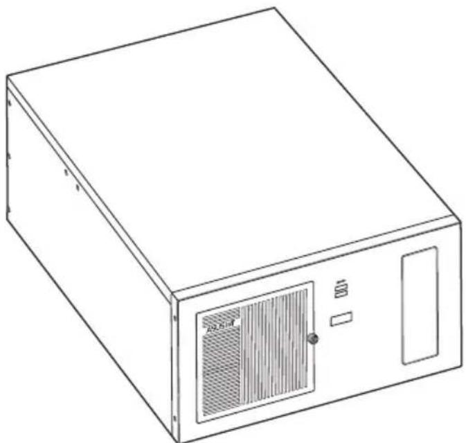
natural_image
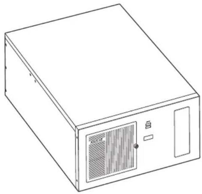
Line drawing of a rectangular electronic device with ventilation grilles and a control panel (no text or symbols)The illustrations in this user manual are for reference only. Actual product may vary.
1.1 Welcome!
Thank you for choosing the ASUS EBS-A700!
The ASUS EBS-A700 provides cutting-edge performance and uncompromised reliability for industrial use.
The system is powered by the ASUS motherboard that supports the Intel ^® 13 ^th /12 ^th Gen. Core ^™ i9 / i7 / i5 / i3, Pentium ^® and Celeron ^® processors in the Intel ^® socket 1700.
The system supports up to 64 GB of system memory using DDR4 3200 MHz DIMMs. High-resolution graphics via PCI Express x16 slots, SATA 6.0Gb/s, USB 3.2 Gen 1 ports, and USB 2.0 ports take you ahead in the world of power computing.
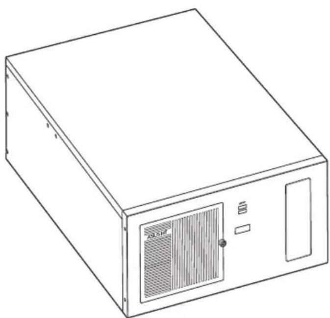
1.2 Brief introduction
• Color: Black (EBS-A700)
• Net weight: refer to the data sheet
• Form factor: 445mm x 330mm x 196mm

text_image
445mm 330mm 196mm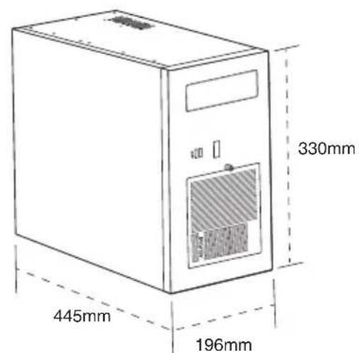
text_image
330mm 445mm 196mm• Operation temperature: 0\~40°C
• Non-operation temperature: -15\~60°C
- Relative humidity:10\~95%@40°C,non-condensing
- OS support:
Windows ^® 10 (64bit)
Windows® 10 IoT Enterprise
Ubuntu
RedHat Enterprise
Fedora Workstation
OpenSUSE
| Main components | |
 |  |
| Chassis | Motherboard (ASUS H610A-IM-A) |
 |  |
| Power supply unit | Accessory box |
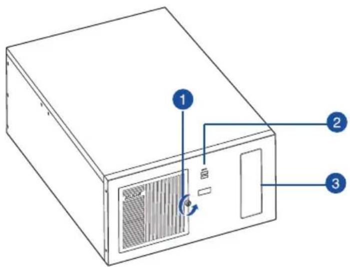
1.3 Front panel
The front panel includes the 5.25"CD-ROM bay and USB 3.2 Gen 1 ports.
text_image
Diagram of a computer tower with labeled components and directional arrows indicating rotation or ventilation.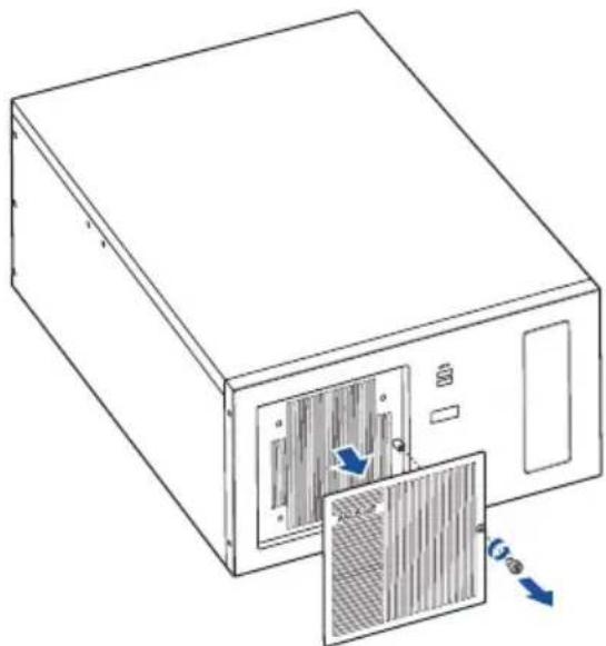
natural_image
Line drawing of a computer tower with ventilation slots and a door, showing internal components and airflow direction (no text or symbols)- Cabinet cover. Remove the screw to remove the cabinet cover.
- USB 3.2 Gen 1 (up to 5Gbps) ports. These 9-pin Universal Serial Bus (USB) ports are for USB 3.2 Gen 1 devices.
- 5.25-inch CD-ROM bay. Allows you to install a CD-ROM in this bay.
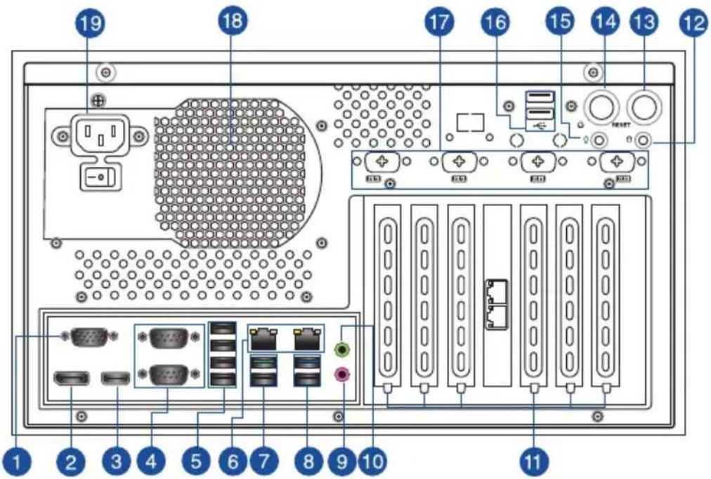
1.4 Rear panel
The system rear panel includes the power connector and several I/O ports that allow convenient connection of devices.
text_image
19 18 17 16 15 14 13 12 10 11 1 2 3 4 5 6 7 8 9 10- Video Graphics Adapter (VGA) port. This 15-pin port is for a VGA monitor or other VGA-compatible device.
- DisplayPort. This port is for a DisplayPort-compatible device.
- HDMI™ ports. These ports are for a High-Definition Multimedia Interface (HDMI™) connector, and are HDCP compliant allowing playback of HD DVD, Blu-ray, and other protected content.
- COM ports (COM, RS232/RS422/RS485). These ports connect modems, or other devices that conform with serial specification.
| RS232 RS485 RS422 | |||
| Pin1 DCD B T(B) | |||
| Pin2 RXD A T(A) | |||
| Pin3 TXD NC R(A) | |||
| Pin4 DTR NC R(B) | |||
| Pin5 GND GND GND | |||
| Pin6 DSR NC NC | |||
| Pin7 RTS NC NC | |||
| Pin8 CTS NC NC | |||
| Pin9 RI/5V/12V NC/5V/12V NC/5V/12V | |||
-
USB 2.0 ports. These 4-pin Universal Serial Bus (USB) ports are for USB 2.0 devices.
-
LAN (RJ-45) ports. These ports allow Gigabit connection to a Local Area Network (LAN) through a network hub.
LAN port LED indications
| Active LED | Link LED | |
| Status Description Status Description | ||
| OFF No link OFF | 10Mbps connection | |
| ORANGE Linked ORANGE | 100Mbps connection | |
| BLINKING Data activity GREEN 1Gbps connection | ||
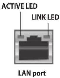
text_image
ACTIVE LED LINK LED LAN port- USB 3.2 Gen 2 (up to 10Gbps) ports. These 9-pin Universal Serial Bus (USB) ports are for USB 3.2 Gen 2 devices.
- USB 3.2 Gen 1 (up to 5Gbps) ports. These 9-pin Universal Serial Bus (USB) ports are for USB 3.2 Gen 1 devices.
- Microphone port (pink). This port connects to a microphone.
- Line Out port (lime). This port connects to a headphone or a speaker. In the 4.1, and 5.1 channel configurations, the function of this port becomes Front Speaker Out.

Refer to the audio configuration table for the function of the audio ports in 2, 4, 5.1, or 7.1-channel configuration.
Audio 2, 4, 5.1 or 7.1-channel configuration
| Port | Headset 2-channel | 4-channel 5.1-channel 7.1-channel | ||
| Lime (Rear panel) | Line Out | Front Speaker Out | Front Speaker Out | Front Speaker Out |
| Pink (Rear panel) | Mic In | Mic In | Bass/Center | Bass/Center |
| Lime (Front panel) | - | - | - | Side Speaker Out |

To configure a 7.1-channel audio output:
Use a chassis with HD audio module in the front panel to support a 7.1-channel audio output.
-
Expansion slot brackets. Remove the expansion slot bracket when installing an expansion card.
-
HDD LED. The LED lights up or blinks to indicate the status of the HDD.
- Reset button. Press this button to reset the system.
- Power button. Press this button to turn the system on.
- Power LED. The LED lights up or blinks to indicate the status of the system power.
- USB 2.0 ports. These 4-pin Universal Serial Bus (USB) ports are for USB 2.0 devices.
- Serial ports (optional). These 9-pin COM ports are for pointing devices or other serial devices.
- Power supply unit fan vent. This vent is for the PSU fan that provides ventilation inside the power supply unit.
- Power connector. Plug the power cord to this connector.

RATING:100V-240V\~8.0A, 47Hz-63Hz (China)
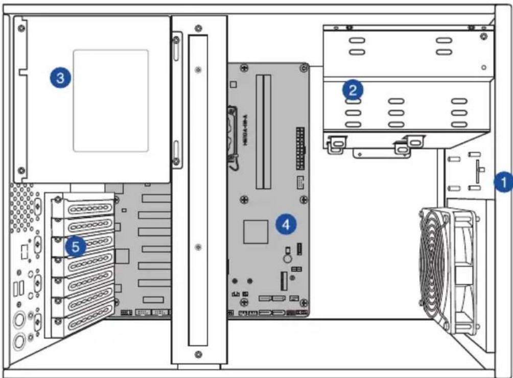
1.5 Internal components
The illustration below is the internal view of the system when you remove the chassis cover and the power supply unit. The installed components are labeled for your reference.
text_image
Diagram of a computer tower rear panel showing labeled components including CPU, drive, and chassis- Front panel cover
- 5.25-inch optical drive bay
3.5-inch drive bays
2.5-inch SSD bay -
Power supply unit
-
ASUS motherboard
- Metal bracket lock
1.6 Mounting the chassis
Attach the brackets to the bottom side of the chassis with the bundled screws (6 * M4.0 x 6L).

text_image
Technical diagram of a computer tower with labeled drive ports and blue directional arrows indicating movement or flow.Chapter 2
This chapter provides details about the motherboard that comes with the system. This chapter includes the motherboard layout, jumper settings, and connector locations.
natural_image
Line drawing of a rectangular electronic device with ventilation grilles and ports (no text or symbols)2.1 Motherboard layout

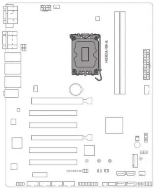
text_image
24.4cm(9.6in) 1 2 3 4 VGA COM1 COM1 SELL COM2 SELL USB_5-3 LAV2_USA02_12 LAV3 LIGHT 30 AUDIO PCIEX18(GS) PCI_1 PCI_2 PCIEX18(G3) PCI_3 PCI_4 PCIEX1(G3) SWEDATA SW SWEDCK SW ATX SEL LAN CPU_FAN CPU_FAN H510A-IM-A DDR4 DIMM A (0-4bit, 288 pin module) DDR4 DIMM B (6-bit, 288-pin module) AXI-VAN USB 914 30.5cm(12in) 5 6 7 8 9 22 ALC 807 PCIEX1(G3) AWF DCAMOSOCOMONICOM LIT KENS CON SATAHG 5 SATAHG 2 SATAHG 1 SATAHG 2 SEAKER CHESER FLOWE| Connectors/Jumpers/Slots Page | ||
| 1. COM RING/+5V/+12V selection (COM1/2_SEL) 2-6 | ||
| 2. ATX Power connectors (24-pin ATXPWR, 2 x 4-pin EATX12V) 2-8 | ||
| 3. Intel ® LGA1700 CPU socket 2-4 | ||
| 4. DDR4 U-DIMM slots 2-4 | ||
| 5. USB 2.0 header (10-1pin USB914) 2-9 | ||
| 6. TPM header (14-1 pin TPM) 2-9 | ||
| 7. I2C header (6-1 pin I2C) 2-10 | ||
| 8. M2 slot (SOCKET 3) 2-10 | ||
| 9. System Panel header (10-1 pin F_PANEL) 2-11 | ||
| 10. Speaker header (4-pin SPEAKER) 2-12 | ||
| 11. Chassis Intrusion header (4-1 pin CHASSIS) 2-12 | ||
| 12. SATA 6.0 Gb/s ports (7-pin SATA6G_1-4) 2-13 | ||
| 13. General Purpose Input/Output header (GPIO_CON) 2-13 | ||
| 14. PS/2 Keyboard & Mouse header (8-pin KBMS_CON) 2-14 | ||
| 15. Clear RTC RAM (2-pin CLRTC) | 2-5 | |
| 16. LPT header (26-1 pin LPT) | 2-14 | |
| 17. AT/ATX mode selection jumper (3-pin AT_ATX_SEL) | 2-6 | |
| 18. 3-pin SMBDATA_SW | 2-7 | |
| 19. 3-pin SMBCLK_SW | 2-7 | |
| 20. COM Port headers (10-1 pin COM3 - COM6) | 2-15 | |
| 21. Front Panel Audio header (10-1 pin AAFP) 2-16 | ||
| 22. COM Debug header (COM_DEBUG) | 2-8 | |
2.2 Central Processing Unit (CPU)
The motherboard comes with a surface mount LGA1700 socket designed for the Intel® Core™ i9 / Core™ i7 / Core™ i5 / Core™ i3, Pentium®, and Celeron® Processors.
text_image
HERRA-10-A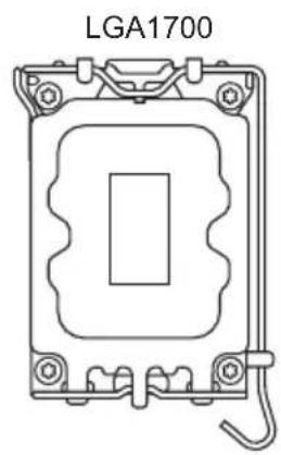
natural_image
Technical line drawing of an LGA1700 component with mounting holes and a central rectangular cutout (no text or symbols)2.3 System memory
This motherboard comes with two Double Data Rate 4 (DDR4) Dual Inline Memory Module (DIMM) sockets. The figure below illustrates the location of the DDR4 DIMM sockets:
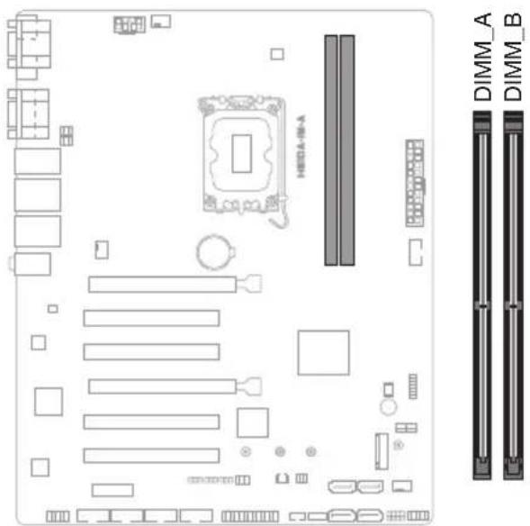
text_image
DIMM_A DIMM_B| Channel Sockets |
| Channel A DIMM_A |
| Channel B DIMM_B |
2.4 Jumpers
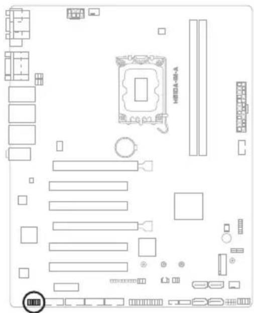
1. Clear RTC RAM (2-pin CLRTC)
This header allows you to clear the CMOS RTC RAM data of the system setup information such as date, time, and system passwords.

text_image
HIFDA-16-A CLRTC PIN 1 +3V_BAT_RTC GNDConnector type
HEADER 1x2p, 2.54mm pitch, S/T
To erase the RTC RAM:
- Turn OFF the computer and unplug the power cord.
- Use a metal object such as a screwdriver to short the two pins.
- Plug the power cord and turn ON the computer.
- Hold down the
key during the boot process and enter BIOS setup to re-enter data.

If the steps above do not help, remove the onboard battery and move the jumper again to clear the CMOS RTC RAM data. After clearing the CMOS, reinstall the battery.
2. COM Ring/+5V/+12V selection jumper (6-pin COM1/2\_SEL)

text_image
A COM1_SEL B COM2_SEL 2 4 6 1 3 +5V+12V 5 RI (Default)| Setting Pins | |
| +12V 1-2 | |
| +5V 3-4 | |
| Ring (Default) 5-6 |
3. AT/ATX mode selection jumper (3-pin AT\_ATX\_SEL)
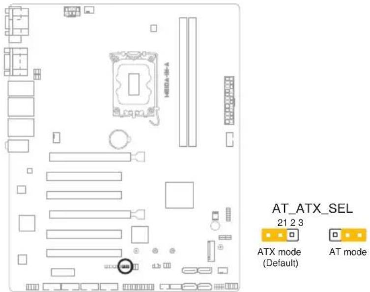
text_image
HAVA-06-A AT_ATX_SEL 21 2 3 ATX mode (Default) AT mode| Pins | |
| 1-2 (Default) ATX mode | |
| 2-3 AT mode |
| Connector type | HEADER 1x3p, 2.54mm pitch, S/T |
4. 3-pin SMBDATA\_SW

text_image
H8DA-48-A
text_image
SMBDATA_SW 21 2 3 Eanble PCIe SMBus connection (Default) Disable PCIe SMBus connection| Setting Pins | |
| Enable PCIe SMBus connection (Default) 1-2 | |
| Disable PCIe SMBus connection 2-3 | |
5. 3-pin SMBCLK\_SW

text_image
Diagram of a computer motherboard layout with labeled components and connectors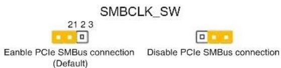
text_image
SMBCLK_SW 21 2 3 Eanble PCIe SMBus connection (Default) Disable PCIe SMBus connection| Settings | Pins | |
| Enable PCIe SMBCLK connection (Default) | 1-2 | |
| Disable PCIe SMBCLK connection 2-3 | ||
2.5 Internal connectors
1. ATX Power connectors (24-pin ATXPWR, 2 x 4-pin EATX12V)
Correctly orient the ATX power supply plugs into these connectors and push down firmly until the connectors completely fit.
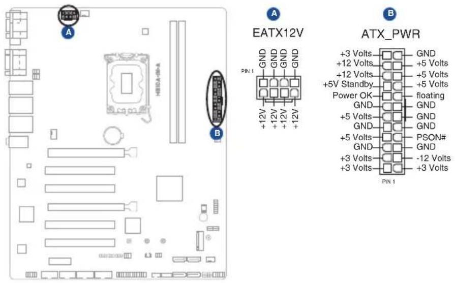
text_image
A H80A-06-A B EATX12V GND GND GND GND +12V +12V +12V +12V PIN 1 B ATX_PWR +3 Volts GND +12 Volts +5 Volts +12 Volts +5 Volts +5V Standby +5 Volts Power OK floating GND GND +5 Volts GND GND GND +5 Volts PSON# GND GND +3 Volts -12 Volts +3 Volts +3 Volts PIN 1| Connector type | POWER CON 24P S/T |
| POWER CON 8P S/T |
2. COM Debug header (COM\_DEBUG)
This header allows connection to a COM Debug card.

text_image
HEDA-18-A COM_DEBUG PIN 1 GND GND debug_control TXD +3VConnector type HEADER 2x3p, K3, 2.54 mm pitch, S/T

The COM Debug Card is purchased separately.
3. USB 2.0 header (10-pin USB914)
This header is for USB 2.0 ports. Connect a USB cable to the header. The USB header complies with USB 2.0 specification that supports up to 480 Mbps connection speed.

text_image
USB914 NC GND GND USB_P9+ USB_P14+ USB_P9- USB_P14- USB+5V USB+5V PIN 1Connector type
HEADER 2x5p, K9, 2.54mm pitch

Never connect a 1394 cable to the USB connector. Doing so will damage the motherboard.

The USB cable is purchased separately.
4. TPM header (14-1 pin TPM)
This header supports a Trusted Platform Module (TPM) system with a Serial Peripheral Interface (SPI), allowing you to securely store keys, digital certificates, passwords and data. A TPM system also enhances network security, protects digital identities, and ensures platform integrity.

text_image
TPM PIN 1 +3VSB PLTRST# +3VSB SPI SPI CS# SPI MISO SPI HOLD# SPI TPM IRQ# SPI TPM CS# GND SPI FLASH WP# SPI CLK SPI MOSIConnector type
HEADER 2x7p, K14, 2.0mm pitch
5. I²C header
The I²C (Inter-Integrated Circuit) header allows you to connect an I²C compatible IoT security module.
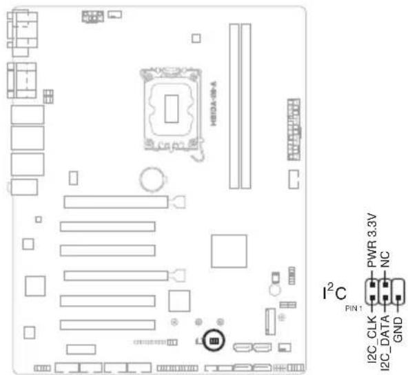
text_image
H80A-08-A I²C PIN1 I2C_CLK PWR 3.3V NC GNDConnector type
HEADER 2x3p, K6, 2.0mm pitch
6. M.2 slot (SOCKET 3)
This slot allows you to install an M.2 SSD module.
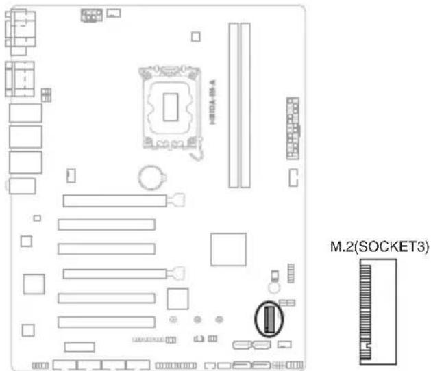
text_image
H100A-BA M.2(SOCKET3)Connector type
NGFF KEY-M 67P, 8.5H

- The M.2 SSD module is purchased separately.
- This slot supports M Key and 2242/2260/2280 storage devices.
7. System Panel header (10-1 pin F\_PANEL)
This header supports several chassis-mounted functions.

text_image
HEDA-W-A F_PANEL +PWR_LED PWR_BTN PLED+ PLED- PWRBTN#_PANEL GND PIN1 HDD_LED+ HDD_LED- GND O_RSTCON#_PR NC +HDD_LED RESETConnector type
HEADER 2x5p, K10, 2.54mm pitch
- System power LED (2-pin +PWR\_LED)
This 2-pin header is for the system power LED. Connect the chassis power LED cable to this header. The system power LED lights up when you turn on the system power, and blinks when the system is in sleep mode.
• Hard disk drive activity LED (2-pin +HDD\_LED)
This 2-pin header is for the HDD Activity LED. Connect the HDD Activity LED cable to this header. The IDE LED lights up or flashes when data is read from or written to the HDD.
- ATX power button/soft-off button (2-pin PWR\_BTN)
This 2-pin header is for the system power button.
- Reset button (2-pin RESET)
This 2-pin header is for the chassis-mounted reset button for system reboot without turning off the system power.
8. Speaker header (4-pin SPEAKER)
The 4-pin header is for the chassis-mounted system warning speaker. The speaker allows you to hear system beeps and warnings.
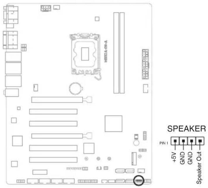
text_image
H801A-04-A SPEAKER PIN 1 +5V GND GND Speaker OutConnector type
HEADER 1x4p, 2.54mm pitch, S/T
9. Chassis Intrusion header (4-1 pin\_CHASSIS)
This header is for a chassis-mounted intrusion detection sensor or switch. Connect one end of the chassis intrusion sensor or switch cable to this connector. The chassis intrusion sensor or switch sends a low-level signal to this connector when a chassis component is installed. The signal is then generated as a chassis intrusion event.
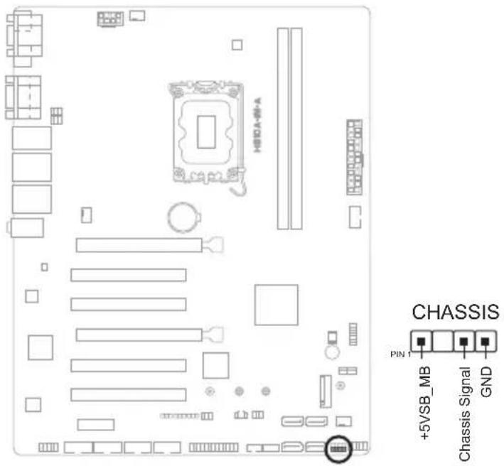
text_image
H80A-64-A CHASSIS PIN 1 +5V/SB_MB Chassis Signal GNDConnector type
HEADER 4p, K2, 2.54mm pitch
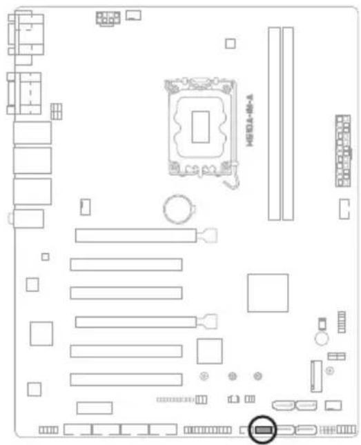
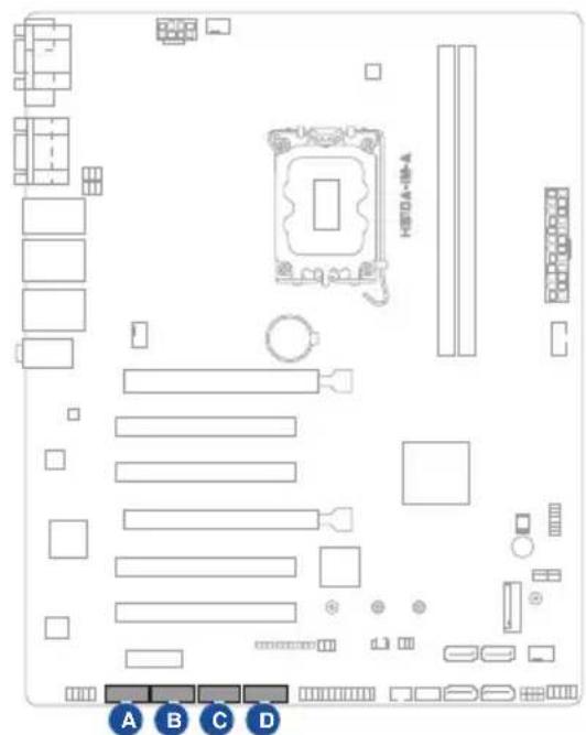
10. SATA 6.0Gb/s ports (7-pin SATA6G\_1-4)
These ports connect to SATA 6.0 Gb/s hard disk drives or an optical drive via SATA 6.0 Gb/s signal cables.
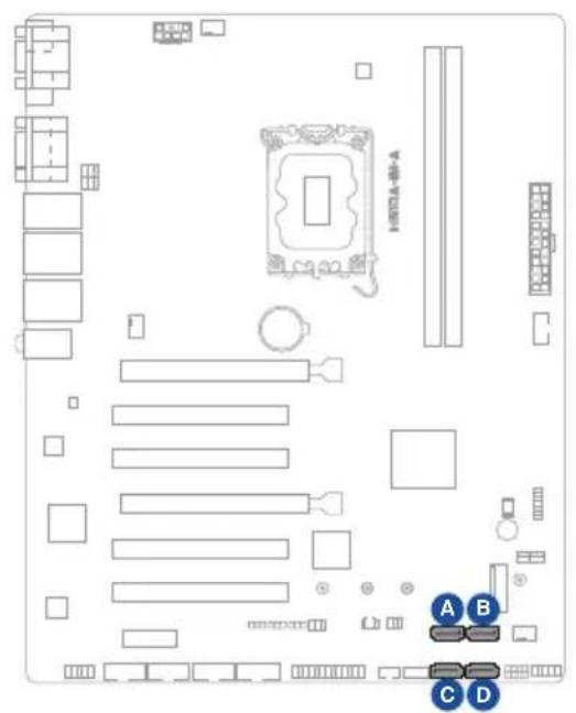
text_image
Diagram of a computer motherboard layout with labeled components and connectors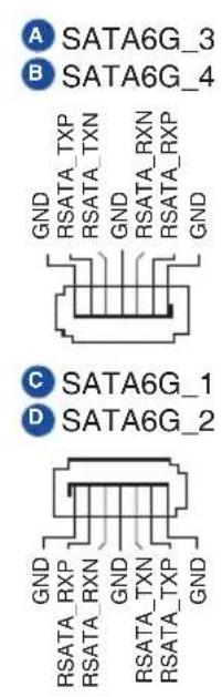
A SATA6G_3
B SATA6G_4
GND
RSATA_TXP
RSATA_TXN
GND
RSATA_RXN
RSATA_RXP
GND
C SATA6G_1
D SATA6G_2
Connector type
SATA CON 7P S/T
11. General Purpose Input/Output header (GPIO\_CON)
This header is for a general purpose input/output module which allows you to customize the digital signal input/output.
text_image
Diagram of a computer motherboard layout with labeled components and a highlighted CPU socket
text_image
GPIO_CON +3V GND GPIO8 GPIO6 GPIO4 GPIO2 GPIO7 GPIO5 GPIO3 GPIO1 PIN 1Connector type
WAFER HD 2x5p, 2.0mm pitch, S/T
12. PS/2 Keyboard & Mouse header (8-pin KBMS\_CON)
This header is for an IBM PS/2-compatible keyboard or mouse.

text_image
KBMS_CON +5V_ZPS2 GND O_MS_DATA_R O_MS_CLK_R +5V_ZPS2 GND O_KB_DATA_R O_KB_CLK_R PIN 1Connector type
WAFER HD 2x4p, 2.0mm pitch, S/T
13. LPT header (26-1 pin LPT)
The LPT (Line Printing Terminal) header supports devices such as a printer. LPT is standardized as IEEE 1284, which is the parallel port interface on IBM PC-compatible computers.
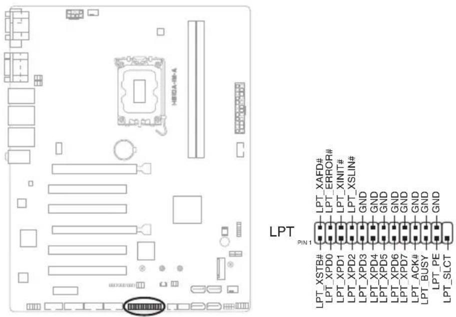
text_image
HEDA-08-A LPT PIN 1 LPT_XAFD# LPT_ERROR# LPT_XINIT# LPT_XSLIN# GND LPT_XPD0 LPT_XPD1 LPT_XPD2 LPT_XPD3 LPT_XPD4 LPT_XPD5 LPT_XPD6 LPT_XPD7 LPT_ACK# LPT_BUSY LPT_PE LPT_SLCTConnector type
HEADER 2x13p, K26, 2.54mm pitch, S/T
14. COM Port headers (10-1 pin COM3 - COM6)
These headers are for serial (COM) ports. Connect the serial port cables to these headers, then install the module to a slot opening at the back of the system chassis.
text_image
HSDA-18-A A B C D
COM3

COM4

COM5

COM6

Connector type
HEADER 2x5p, K10, 2.54mm pitch

The serial port cable is purchased separately.
15. Front Panel Audio header (10-1 pin AAFP)
This header is for a chassis-mounted front panel audio I/O module that supports HD Audio standard. Connect one end of the front panel audio I/O module cable to this header.
text_image
Diagram of a computer motherboard layout with labeled components and connectors
text_image
AAFP PIN 1 A_GND NC A_JD_FMIC1 A_FMIC1_L A_FMIC1_R A_HPOUT_R A_JD_FRONT A_JD_HPOUT A_HPOUT_LConnector type
HEADER 2x5p, K8, 2.54mm pitch

- We recommend that you connect a high-definition front panel audio module to this header to avail of the motherboard's high-definition audio capability.
- If you want to connect a high-definition front panel audio module to this header, set the HD Audio Controller item in the BIOS setup to [Enabled].
Chapter 3
This chapter provides a detailed guide to navigating and setting up the BIOS.
natural_image
Line drawing of a rectangular electronic device with ventilation grilles and a control panel (no text or symbols)BIOS setup
3.1 BIOS setup program
Use the BIOS Setup program to update the BIOS or configure its parameters. The BIOS screens include navigation keys and brief online help to guide you in using the BIOS Setup program.
Entering BIOS Setup at startup
To enter BIOS Setup at startup:
Press during the Power-On Self Test (POST). If you do not press , POST continues with its routines.
Entering BIOS Setup after POST
To enter BIOS Setup after POST:
- Press
+ + simultaneously. - Press the reset button on the system chassis.
- Press the power button to turn the system off then back on. Do this option only if you failed to enter BIOS Setup using the first two options.

Using the power button, reset button, or the keys to reboot a running operating system can cause damage to your data or system. Always shut down the system properly from the operating system.

- Visit the ASUS website at www.asus.com to download the latest BIOS file for this motherboard.
- The default BIOS settings for this motherboard apply to most working conditions and ensures optimal performance. If the system becomes unstable after changing any BIOS settings, load the default settings to regain system stability. Select the option Restore Defaults under the Exit Menu or press hotkey F3.
- The BIOS setup screens shown in this section are for reference purposes only, and may not exactly match what you see on your screen.
3.1.1 BIOS menu screen
Menu bar
The menu bar on top of the screen has the following main items:
Main For changing the basic system configuration
Advanced For changing the advanced system settings
Hardware Monitor For displaying the system temperature and changing the fan settings
Security For configuring the system security settings
Boot For changing the system boot configuration.
Exit For selecting the save options and default options.
To select an item on the menu bar, press the right or left arrow key on the keyboard until the desired item is highlighted.
3.2 Main menu
The Main menu provides you an overview of the basic system information, and allows you to set the system date, time, language, and security settings.
3.2.1 System Date [Day MM/DD/YYYY]
Allows you to set the system date.
3.2.2 System Time [HH:MM:SS]
Allows you to set the system time.
3.3 Advanced menu
The Advanced menu items allow you to change the settings for the CPU and other system devices.

Be cautious when changing the settings of the Advanced menu items. Incorrect field values can cause the system to malfunction.
3.3.1 PCH-FW Configuration
TPM Device Selection
This item allows you to select the TPM device. Configuration options: [dTPM] [PTT]
3.3.2 Trusted Computing
Security Device Support
This item allows you to enable or disable BIOS support for security devices.
Configuration options: [Disable] [Enable]
3.3.3 CPU Configuration
The items in this menu show CPU-related information the BIOS automatically detects.

The items shown in the submenu may be different depending on the type of CPU installed.
Intel (VMX) Virtualization Technology
When set to [Enabled], a VMM can utilize the additional hardware capabilities provided by Vanderpool Technology. Configuration options: [Disabled] [Enabled]
Hyper-Threading
The Intel Hyper-Threading Technology allows a hyper-threading processor to appear as two logical processors to the operating system, allowing the operating system to schedule two threads or processes simultaneously.
[Enabled] Two threads per activated core are enabled.
[Disabled] Only one thread per activated core is enabled.
Intel Trusted Execution Technology
When set to [Enabled], allows you to enable the utilization of additional hardware capabilities provided by Intel® Trusted Execution Technology and requires a full power cyle. Configuration options: [Disabled] [Enabled]
VT-d [Disabled]
Allows you to enable or disable VT-d function on MCH. Configuration options: [Disabled] [Enabled]
CPU Power Management Control
This item allows you to manage and configure the CPU's power.
Intel(R) SpeedStep(tm)
This item allows your system to support more than two frequency ranges. Configuration options: [Disabled] [Enabled]
Intel(R) Speed Shift Technology
This item allows you to enable or disable Intel(R) Speed Shift Technology support. When enabled, CPPC v2 interface allows hardware controlled P-state. Configuration options: [Disabled] [Enabled]
Turbo Mode
This item allows you to enable or disable Turbo Mode for your processor. Configuration options: [Enabled] [Disabled]
CPU C states
[Enabled] Enables the CPU C states. [Disabled] Disables the CPU C states
Enhanced C-states
[Disabled] Disables enhanced C1 state. [Enabled] Enables enhanced C1 state.
Power Limit 1 Override
[Disabled] Disables power limit 1. [Enabled] Enables power limit 1.
Power Limit 2 Override
[Disabled] Disables power limit 2. [Enabled] Enables power limit 2.
Power Limit 2
This item allows you to input the value of power limit 2 in milliwatts. If the value is 0, BIOS will program this value as 1.25 times of Processor Base Power (TDP). For 12.50W, enter 12500. Processor applies control policies so that the package power does not exceed this limit.
3.3.4 Graphics Configuration
Allows you to select a primary display from IGFX, PEG and PCI graphical devices.
Primary Display
Allows you to select which of the IGFX/PEG/PCI Graphics device should be the Primary Display. Configuration options: [Auto] [IGFX] [PEG Slot] [PCH PCI]
Internal Graphics
[Auto] Keep IGFX enabled base on the setup options.
[Disabled] Disables internal graphics.
[Enabled] Enables internal graphics.
RC6 (Render Standby)
Allows you to enable or disable render standby support. Configuration options:
[Disabled] [Enabled]
3.3.5 PCI Express Configuration
Allows you to select a PEG or PCI graphical device.
PCIEX16 (G5) Slot
PCIEx16 (G5) Slot
This item allows you to enable or disable the PCIEX16 (G5) slot.
Configuration options: [Disabled] [Enabled]
ASPM
This item allows you to control the Active State Power Management on both NB (NorthBridge) side and SB (SouthBridge) side of the DMI Link.
Configuration options: [Disabled] [L0s] [L1] [L0sL1]
L1 Substates
This item allows you to select the PCI Express L1 Substates settings.
Configuration options: [Disabled] [L1.1] [L1.1 & L1.2]
PCIe Speed
Configures the speed of PCIEX16 (G5) slot. Configuration options: [Auto]
[Gen1] [Gen2] [Gen3] [Gen4] [Gen5]
Detect Timeout
Allows you to set the time (milliseconds) of waiting for link to exit Detect state for enabled ports before assuming there is no device and potentially disabling the port. Use the <+> and <-> keys to adjust the value or input the desired value.
Hot Plug
These items allow you to enable/disable PCIEX16 (G5) slot Hot Plug support.
Configuration options: [Disabled] [Enabled]
Detect Non-Compliance Device
Allows you to enable or disable the detection function of non-compliance PCI
Express device. Configuration options: [Disabled] [Enabled]
PCIEX16 (G3) Slot
PCIEx16 (G3) Slot
This item allows you to enable or disable the PCIEX16 (G3) slot.
Configuration options: [Disabled] [Enabled]
ASPM
This item allows you to control the Active State Power Management on both NB (NorthBridge) side and SB (SouthBridge) side of the DMI Link. Configuration options: [Disabled] [L1] [Auto]
L1 Substates
This item allows you to select the PCI Express L1 Substates settings. Configuration options: [Disabled] [L1.1] [L1.1 & L1.2]
PCIe Speed
Configures the speed of PCIEx16 (G3) slot. Configuration options: [Auto] [Gen1] [Gen2] [Gen3]
Detect Timeout
Allows you to set the time (milliseconds) of waiting for link to exit Detect state for enabled ports before assuming there is no device and potentially disabling the port. Use the <+> and <-> keys to adjust the value or input the desired value.
Hot Plug
These items allow you to enable/disable PCIEX16 (G3) slot Hot Plug support. Configuration options: [Disabled] [Enabled]
Detect Non-Compliance Device
Allows you to enable or disable the detection function of non-compliance PCI Express device. Configuration options: [Disabled] [Enabled]
PCIEX1 (G3) Slot
PCIEx1 (G3) Slot
This item allows you to enable or disable the PCIEx1 (G3) slot. Configuration options: [Disabled] [Enabled]
ASPM
This item allows you to control the Active State Power Management on both NB (NorthBridge) side and SB (SouthBridge) side of the DMI Link. Configuration options: [Disabled] [L1] [Auto]
L1 Substates
This item allows you to select the PCI Express L1 Substates settings. Configuration options: [Disabled] [L1.1] [L1.1 & L1.2]
PCIe Speed
Configures the speed of PCIEx1 (G3) slot. Configuration options: [Auto] [Gen1] [Gen2] [Gen3]
Detect Timeout
Allows you to set the time (milliseconds) of waiting for link to exit Detect state for enabled ports before assuming there is no device and potentially disabling
the port. Use the <+> and <-> keys to adjust the value or input the desired value.
Hot Plug
These items allow you to enable/disable PCIEX1 (G3) slot Hot Plug support. Configuration options: [Disabled] [Enabled]
Detect Non-Compliance Device
Allows you to enable or disable the detection function of non-compliance PCI Express device. Configuration options: [Disabled] [Enabled]
3.3.6 CSM Configuration
CSM Support
Allow you to enable/disable the CSM support. Configuration options: [Disabled] [Enabled]
Network
Controls the execution of UEFI and Legacy PXE OpROM. Configuration options: [Do not launch] [UEFI] [Legacy]
Storage
Controls the execution of UEFI and Legacy Storage OpROM. Configuration options: [Do not launch] [UEFI] [Legacy]
Video
Controls the execution of UEFI and Legacy Video OpROM. Configuration options: [Do not launch] [UEFI] [Legacy]
Other PCI devices
Determines OpROM execution policy for devices other than Network, Storage, or Video. Configuration options: [Do not launch] [UEFI] [Legacy]
3.3.7 Super IO Configuration
NCT6126D Super IO Configuration
Serial Port 1 Configuration
Serial Port
Allows you to enable or disable the serial port (COM).Configuration options: [Disabled] [Enabled]

The following items appear only when you set Serial Port to [Enabled].
COM1 Control
Allows you to select the COM1 mode. Configuration options: [RS232] [RS422] [RS485]
Serial Port 2 Configuration
Serial Port
Allows you to enable or disable the serial port (COM).Configuration options: [Disabled] [Enabled]

The following item appears only when you set Serial Port to [Enabled].
COM2 Control
Allows you to select the COM2 mode. Configuration options: [RS232] [RS422] [RS485]
Serial Port 3 Configuration
Serial Port
Allows you to enable or disable the serial port (COM).Configuration options: [Disabled] [Enabled]
Serial Port 4 Configuration
Serial Port
Allows you to enable or disable the serial port (COM).Configuration options: [Disabled] [Enabled]
Serial Port 5 Configuration
Serial Port
Allows you to enable or disable the serial port (COM).Configuration options: [Disabled] [Enabled]
Serial Port 6 Configuration
Serial Port
Allows you to enable or disable the serial port (COM).Configuration options: [Disabled] [Enabled]
Parallel Port Configuration
Parallel Port
Allows you to enable or disable the Parallel port (LPT/LPTE).Configuration options: [Disabled] [Enabled]

The following items appear only when you set Parallel Port to [Enabled].
Device Mode
Allows you to select the Parallel Port mode. Configuration options: [STD Printer Mode] [SPP Mode] [EPP-1.9 and SPP Mode] [EPP-1.7 and SPP Mode] [ECP Mode] [ECP and EPP 1.9 Mode] [ECP and EPP 1.7 Mode]
3.3.8 Serial Console Redirection
COM1\~COM6
Console Redirection
Allows you enable or disable the console redirection feature. Configuration options: [Enabled] [Disabled]
Console Redirection Settings
The settings specify how the host computer and the remote computer (which the user is using) will exchange data. Both computers should have the same or compatible settings.
Terminal Type
Configuration options: [VT100] [VT100Plus] [VT-UTF8] [ANSI]
[VT100] ASCII char set.
[VT100Plus] Extends VT100 to support color, function keys, etc.
[VT-UTF8] Uses UTF8 encoding to map Unicode chars onto 1 or more bytes.
[ANSI] Extended ASCII char set.
Bits per second
Allows you to select serial port transmission speed. The speed must be matched on the other side. Long or noisy lines may require lower speeds.
Configuration options: [9600] [19200] [38400] [57600] [115200]
Data Bits
Configuration options: [7] [8]
Parity
A parity bit can be sent with the data bits to detect some transmission errors.
Configuration options: [None] [Even] [Odd] [Mark] [Space]
[None] Disables parity check.
[Even] Parity bit is 0 if the num of 1's in the data bits is even.
[Odd] Parity bit is 0 if the num of 1's in the data bits is odd.
[Mark] Parity bit is always 1.
[Space] Parity bit is always 0.

Mark and Space Parity do not allow for error detection.
Stop Bits
Stop bits indicate the end of a serial data packet. The standard setting is 1 stop bit. Communication with slow devices may require more than 1 stop bit.
Configuration options: [1] [2]
Flow Control
Flow control can prevent data loss from buffer overflow. When sending data, if the receiving buffers are full, a “stop” signal can be sent to stop the data flow. Once the buffers are empty, a “start” signal can be sent to re-start the flow. Hardware flow control uses two wires to send start/stop signals.
Configuration options: [None] [Hardware RTS/CTS]
VT-UTF8 Combo Key Support
Allows you to enable or disable VT-UTF8 Combination Key Support for ANSI/VT100 terminals. Configuration options: [Disabled] [Enabled]
Recorder Mode
With this mode enabled only text will be sent. This is to capture Terminal data. Configuration options: [Disabled] [Enabled]
Resolution 100x31
Allows you to enable or disable extended terminal resolution.
Configuration options: [Disabled] [Enabled]
Putty KeyPad
Allows you to select FunctionKey and KeyPad on Putty.
Configuration options: [VT100] [LINUX] [XTERMR6] [SCO] [ESCN] [VT400]
3.3.9 SATA Configuration
This item allows you to configure SATA device options settings.
SATA Controller(s)
Allows you to enable or disables the onboard SATA device.
Configuration options: [Disabled] [Enabled]

The following item appears only when you set SATA Controller(s) to [Enabled].
SATA Mode Selection
Allows you to determine how SATA controller(s) operate. Configuration options: [AHCI]
[AHCI] Set to [AHCI] when you want the SATA hard disk drives to use the AHCI (Advanced Host Controller Interface). The AHCI allows the onboard storage driver to enable advanced Serial ATA features that increases storage performance on random workloads by allowing the drive to internally optimize the order of commands.
SATA6G\_1/2/3/4
Allow you to enable/disable the SATA6G_1/2/3/4 port. Configuration options: [Disabled] [Enabled]
Hot Plug
Allow you to enable/disable the hot plug function. Configuration options: [Disabled] [Enabled]
3.3.10 Network Stack Configuration
Network Stack
This item allows user to disable or enable the UEFI network stack. Configuration options: [Disabled] [Enabled]

The following two items appear only when you set the previous item to [Enabled].
Ipv4 PXE Support
This item allows user to disable or enable the lpv4 PXE Boot support. Configuration options: [Disabled] [Enabled]
Ipv6 PXE Support
This item allows user to disable or enable the lpv6 PXE Boot support. Configuration options: [Disabled] [Enabled]
3.3.11 USB Configuration
Legacy USB Support
Configuration options: [Enabled] [Disabled] [Auto]
[Enabled] Enables Legacy USB support.
[Disabled] Keeps USB devices available only for EFI applications.
[Auto] Allows the system to detect the presence of USB devices at startup. If any USB device(s) is detected, the USB controller legacy mode is enabled. If none is detected, the legacy USB support is disabled.
XHCI Hand-off
This item functions as a workaround for OSes without XHCI hand-off support. The XHCI ownership change should be claimed by XHCI driver. Configuration options: [Enabled] [Disabled]
USB Mass Storage Driver Support
Allows you to enable or disable USB Mass Storage Driver Support. Configuration options: [Disabled] [Enabled]
U32G2\_1/2
Allows you to enable or disable the USB port. Once set to [Disabled], any USB devices plugged into the connector will not be detected by BIOS or OS. Configuration options: [Disabled] [Enabled]
U32G1\_3/4
Allows you to enable or disable the USB port. Once set to [Disabled], any USB devices plugged into the connector will not be detected by BIOS or OS. Configuration options: [Disabled] [Enabled]
USB5-9, 14
Allows you to enable or disable USB port. Once set to [Disabled], any USB devices plugged into the connector will not be detected by BIOS or OS.
Configuration options: [Disabled] [Enabled]
3.3.12 NVMe Configuration
The NVMe Configuration menu displays the NVMe controller and drive information of the devices connected and allows you to configure NVMe device options settings.
3.3.13 Onboard Devices Configuration
HD Audio
[Enabled] Enables the HD Audio Device.
[Disabled] Disables the HD Audio Device.
LAN1 I210AT
[Enabled] Enables the Intel LAN1 controller.
[Disabled] Disables the controller.
LAN2 I219V
[Enabled] Enables the Intel LAN2 controller.
[Disabled] Disables the controller.
M.2 Key
PCIE Port
[Enabled] Enables the PCIE port.
[Disabled] Disables the PCIE port.
I2C Controller
[Enabled] Enables the I2C controller.
[Disabled] Disables the I2C controller.
3.3.14 Miscellaneous
DMI/OPI Configuration
DMI LINK ASPM Control
This item allows you to control the Active State Power Management on SA side of the DMI Link. Configuration options: [Disabled] [Auto] [ASPM L0s] [ASPM L1] [ASPM L0sL1]
PCI Express Configuration
DMI Link ASPM Control
This item allows you to control the Active State Power Management of the DMI Link. Configuration options: [Disabled] [L1] [Auto]
3.3.15 APM Configuration
ErP Ready
Allows you to switch off some power at S5 to get the system ready for ErP requirement. When set to [Enabled], all other PME options will be switched off. Configuration options: [Disabled] [Enabled]
Restore AC Power Loss
[S5 State] The system goes into off state after an AC power loss. [S0 State] The system goes into on state after an AC power loss.
Power On By PCIE/PCI
This item allows you to enable or disable the Wake-on-LAN function of the onboard LAN controller or other installed PCIe/PCI LAN cards. Configuration options: [Disabled] [Enabled]
Power On By PS2
Enables or disables the system to be powered on by a PS/2 keyboard or mouse. Configuration options: [Disabled] [Enabled]
Power On By Ring
[Enabled] Enables the Ring devices to generate a wake event. [Disabled] Disables the Ring devices to generate a wake event.
Power On By RTC
[Disabled] Disables RTC to generate a wake event. [Single event] Allows you to generate a single wake event. [Daily event] Allows you to generate a daily wake event. [Weekly event] Allows you to generate a weekly wake event. [Monthly event] Allows you to generate a monthly wake event.
3.3.16 EzFlash
Enter Ez-Flash mode
This item allows you to run EzFlash utility. When you press
3.3.17 Watchdog Timer
Watchdog Support
This item allows you to enable or disable Watchdog timer. Configuration options: [Enabled] [Disabled]

The following items appear when you set Watchdog Support to [Enabled].
Watchdog Count mode
Allows you to select Watchdog Timer I count mode.
Configuration options: [Second Mode] [Minute Mode]
Watchdog Timer
Use the <+> and <-> keys to adjust the value or input the desired value directly.
The value ranges from 1 to 255.
3.4 Hardware Monitor menu
The items in this menu provide you an overview of system status including temperature, fan speed and voltage, and allow you to configure the smart fan.
Smart Fan Mode
Allows you to select the smart fan mode. Configuration options: [Disabled] [Normal] [Manual Mode]

The following item appears only when you set Smart Fan Mode to [Manual Mode].
Smart Fan Function
Chassis Fan1/2 Setting
Temperature 1(\~4)
Allows you to set the value of temperature1(\~4).
FD/RPM 1(\~4)
Allows you to set the value of Fan Duty/PRM 1(\~4) when temperature is T1(\~4).
CPU Fan Setting
Temperature 1(\~4)
Allows you to set the value of temperature1(\~4).
FD/RPM 1(\~4)
Allows you to set the value of Fan Duty/PRM 1(\~4) when temperature is T1(\~4).
3.5 Security menu
This menu allows a new password to be created or a current password to be changed. The menu also enables or disables the Secure Boot state and lets the user configure the System Mode state.
Administrator Password
If you have set an administrator password, we recommend that you enter the administrator password for accessing the system.
To set an administrator password:
- Select the Administrator Password item and press
. - From the Create New Password box, key in a password, then press
. - Confirm the password when prompted.
To change an administrator password:
- Select the Administrator Password item and press
. - From the Enter Current Password box, key in the current password, then press
. - From the Create New Password box, key in a new password, then press
. - Confirm the password when prompted.

To clear the administrator password, follow the same steps as in changing an administrator password, but press
User Password
If you have set a user password, you must enter the user password for accessing the system. The User Password item on top of the screen shows the default Not Installed. After you set a password, this item shows Installed.
To set a user password:
- Select the User Password item and press
. - From the Create New Password box, key in a password, then press
. - Confirm the password when prompted.
To change a user password:
- Select the User Password item and press
. - From the Enter Current Password box, key in the current password, then press
. - From the Create New Password box, key in a new password, then press
. - Confirm the password when prompted.
Secure Boot
Secure Boot
Secure Boot can be enabled if the system is running in User mode with enrolled platform Key (EPK) or if the CSM function is disabled. Configuration options: [Disabled] [Enabled]
Secure Boot Mode
In Custom mode, Secure Boot policy variables can be configured by a physically present user without full authentication. Configuration options: [Standard] [Custom]
Key Management
The Key Management item allows you to modify Secure Boot variables and set Key Management page.
Platform Key (PK) / Key Exchange Keys / Authorized Signatures / Forbidden Signatures
Configuration options: [Update] [Append]
3.6 Boot menu
The Boot menu items allow you to change the system boot options.
Boot Configuration
CHASSIS INTRUDE
Allows you to enable or disable the chassis intrusion detection function.
Configuration options: [Disabled] [Enabled]
Setup Prompt Timeout
Allows you to set the number of seconds to wait for setup activation key.
65535(0xFFFF) means indefinite waiting. Configuration options: [1] - [65535]
Boot up NumLock State
[On] Set the power-on state of the NumLock to [On].
[Off] Set the power-on state of the NumLock to [Off].
Quiet Boot
Allows you to enable or disable the Quiet Boot option.
Configuration options: [Disabled] [Enabled]
Fast Boot [Enabled]
[Enabled] Select to accelerate the boot speed.
[Disabled] Select to go back to normal boot.
Boot mode select
Allows you to select the boot mode. Configuration options: [LEGACY] [UEFI]
FIXED BOOT ORDER Priorities
Boot Option #1\~#5
This item allows you to set the system boot order. Configuration options: [Hard
Disk] [NVME] [CD/DVD] [USB Device] [Network] [Disabled]
3.7 Exit menu
The Exit menu items allow you to save or discard your changes to the BIOS items.
Save Changes & Exit
This option allows you to save your changes and exit the Setup program. When you select this option or if you press
Discard Changes & Exit
This option allows you to exit the Setup program without saving your changes. When you select this option or if you press
Save Changes & Reset
This option allows you to exit the Setup program after saving changes.
Discard Changes & Reset
This option allows you to exit the Setup program without saving changes.
Save changes
This option allows you to save changes to any of the setup options you have made so far.
Discard changes
This option allows you to discard changes to any of the setup options you have made so far.
Restore Defaults
Restore/load default values for all the setup options.
Save as User Defaults
This option allows you to save the changes you have made so far as user defaults.
Restore the user defaults with all the setup options.
Appendix
Notices
FCC Compliance Information
Responsible Party: Asus Computer International
Address: 48720 Kato Rd., Fremont, CA 94538, USA
Phone / Fax No: (510)739-3777 / (510)608-4555
This device complies with part 15 of the FCC Rules. Operation is subject to the following two conditions: (1) This device may not cause harmful interference, and (2) this device must accept any interference received, including interference that may cause undesired operation.
This equipment has been tested and found to comply with the limits for a Class B digital device, pursuant to part 15 of the FCC Rules. These limits are designed to provide reasonable protection against harmful interference in a residential installation. This equipment generates, uses and can radiate radio frequency energy and, if not installed and used in accordance with the instructions, may cause harmful interference to radio communications. However, there is no guarantee that interference will not occur in a particular installation. If this equipment does cause harmful interference to radio or television reception, which can be determined by turning the equipment off and on, the user is encouraged to try to correct the interference by one or more of the following measures:
- Reorient or relocate the receiving antenna.
- Increase the separation between the equipment and receiver.
- Connect the equipment into an outlet on a circuit different from that to which the receiver is connected.
- Consult the dealer or an experienced radio/TV technician for help.
HDMI Trademark Notice
The terms HDMI, HDMI High-Definition Multimedia Interface, HDMI Trade dress, and the HDMI Logo are trademarks or registered trademarks of HDMI Licensing Administrator, Inc.

text_image
HDMI™HIGH-DEFINITION MULTIMEDIA INTERFACE
Compliance Statement of Innovation, Science and Economic Development Canada (ISED)
This device complies with Innovation, Science and Economic Development Canada licence exempt RSS standard(s). Operation is subject to the following two conditions: (1) this device may not cause interference, and (2) this device must accept any interference, including interference that may cause undesired operation of the device.
CAN ICES-003 (A)/NMB-003(A)
KC: Korea Warning Statement
Class A:
사용자 안내문
Complying with the REACH (Registration, Evaluation, Authorisation, and Restriction of Chemicals) regulatory framework, we published the chemical substances in our products at ASUS REACH website at http://csr.asus.com/english/REACH.htm.

DO NOT throw the motherboard in municipal waste. This product has been designed to enable proper reuse of parts and recycling. This symbol of the crossed out wheeled bin indicates that the product (electrical and electronic equipment) should not be placed in municipal waste. Check local regulations for disposal of electronic products.

DO NOT throw the mercury-containing button cell battery in municipal waste. This symbol of the crossed out wheeled bin indicates that the battery should not be placed in municipal waste.
ASUS Recycling/Takeback Services
ASUS recycling and takeback programs come from our commitment to the highest standards for protecting our environment. We believe in providing solutions for you to be able to responsibly recycle our products, batteries, other components as well as the packaging materials. Please go to http://csr.asus.com/english/Takeback.htm for detailed recycling information in different regions.
English ASUSTeK Computer Inc. hereby declares that this device is in compliance with the essential requirements and other relevant provisions of related Directives. Full text of EU declaration of conformity is available at: www.asus.com/support
www.asus.com/support
Bosanski ASUSTeK Computer Inc. ovim izjavljuje da je ovaj uređaj usklađen sa bitnim zahtjevima i ostalim odgovarajućim odredbama vezanih direktiva. Cijeli tekst EU izjave o usklađenosti dostupan je na: www.asus.com/support
Service and Support
Visit our multi-language website at https://www.asus.com/support/
