DS300j - NAS ASUS - Free user manual and instructions
Find the device manual for free DS300j ASUS in PDF.

User questions about DS300j ASUS
0 question about this device. Answer the ones you know or ask your own.
Ask a new question about this device
Download the instructions for your NAS in PDF format for free! Find your manual DS300j - ASUS and take your electronic device back in hand. On this page are published all the documents necessary for the use of your device. DS300j by ASUS.
USER MANUAL DS300j ASUS
- Task 1: Unpacking the ASUS Storage (page 2)
- Task 2: Mounting ASUS Storage in a Rack (page 4)
- Task 3: Installing Disk Drives (page 7)
• Task 4: Making Data and Management Connections (page 9)
• Task 5: Setting Up Serial Cable Connections (page 11) - Task 6: Connecting the Power (page 12)
- Task 7: Setting Up the CLI Connection (page 14)
- Contacting Technical Support (page 15)
Task 1: Unpacking the ASUS Storage
The ASUS Storage product box contains the following items:
• ASUS Storage DS300j unit
• Quick Start Guide printed
• RJ11-to-DB9 serial data cable
- Screws for disk drives (70 pieces)
• 1.5m (4.9 ft) Power cords (2)
• CD with User Manual and Quick Start Guide in PDF format
Warning
This is a Class A product. In a domestic environment this product may cause radio interference in which case the user may be required to take adequate measures.

Warning
The electronic components within the ASUS Storage enclosure are sensitive to damage from Electro-Static Discharge (ESD). Observe appropriate precautions at all times when handling the ASUS Storage or its subassemblies.
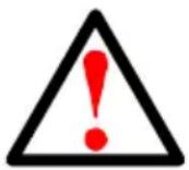
Figure 1. ASUS Storage front view
text_image
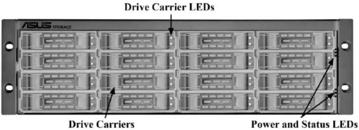
Drive Carrier LEDs ASUS STORAGE Drive Carriers Power and Status LEDsFigure 2. ASUS Storage DS300F rear view
text_image
Dual Power Supplies I/O ModuleFor descriptions of the LEDs, see page 12, Figure 9.
Task 2: Mounting ASUS Storage in a Rack

Cautions
- At least two persons are required to safely lift, place, and attach the ASUS Storage unit into a rack system.
- Do not lift or move the ASUS Storage unit by the handles, power supplies or the controller units. Hold the subsystem itself.
- Do not install the ASUS Storage unit into a rack without rails to support the subsystem.
- Only a qualified technician who is familiar with the installation procedure should mount and install the ASUS Storage unit.
- Be sure all switches are OFF before installing the ASUS Storage unit or exchanging components.
- Mount the rails to the rack using the appropriate screws and flange nuts, fully tightened, at each end of the rail.
- Do not load the rails unless they are installed with screws as instructed.
- The rails available for the ASUS Storage unit are designed to safely support that ASUS Storage unit when properly installed. Additional loading on the rails is at the customer's risk.
- ASUSTek COMPUTER INC. (Taiwan) cannot guarantee that the mounting rails will support your ASUS Storage unit unless you install them as instructed.

Note
To lighten the ASUS Storage enclosure, remove the power supplies. Replace the power supplies after the ASUS Storage unit is mounted in your rack.
The ASUS Storage DS300j unit installs to the rack using the available mounting rails. You can also use your existing rails.
Figure 3. DS300j unit mounted in a rack with the available rails

text_image
Vertical Rack Post ASUS Storage subsystem ASUS STORAGE Handles mount outside the rack post Mounting rails mount outside the rack postTo install the ASUS Storage unit into a rack with the available mounting rails:
- Check the fit of the mounting rails in your rack system.
See page 6, Figure 4.
- Adjust the length of the mounting rails as needed.
The rear rail slides inside the front rail. The rail halves are riveted together and use no adjustment screws.
- Attach the mounting rail assemblies to the outside of the rack posts, using the attaching screws and flange nuts from your rack system.
Be sure the front rail support is on the bottom facing inward.
The alignment pins fit into the rack holes above and below the attaching screws.
Use the attaching screws and flange nuts from your rack system. Tighten the screws and flange nuts according to your rack system instructions.
-
Place the ASUS Storage unit onto the rails.
-
Secure the ASUS Storage unit to the rack.
One screw each side, in the upper hole only. Use the attaching screws and flange nuts from your rack system. Tighten the screws and flange nuts according to your rack system instructions.
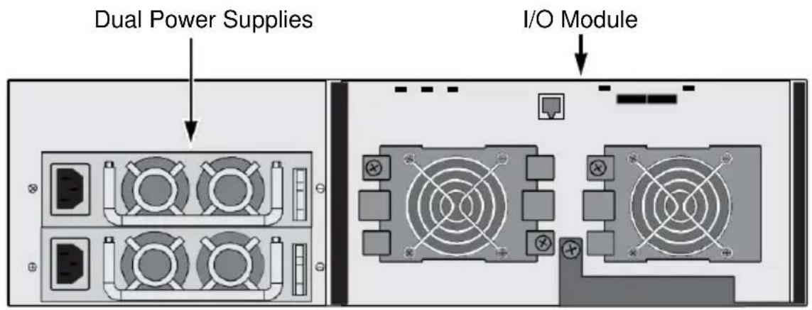
Figure 4. Rack mount assembly diagram
text_image
Rack front post Locating pins (2 on each end) Rail attaching screws (not included) Flange Support Front rail Rear rail Inside of post Rail adjustment screw (center, outside of rail) Inside of post Rack back postThis completes rack mounting. Go to "Task 3: Installing Disk Drives" on page 7.
Task 3: Installing Disk Drives
• SAS and SATA hard disk drives
• 3.5-inch hard disk drives
For a list of supported physical drives, download the latest compatibility list from the ASUS support web site http://support.asus.com/.
Drive Slot Numbering
You can install any suitable disk drive into any slot in the enclosure. The diagram below shows how ASUS Storage's drive slots are numbered. Whether you have the original or plus carriers, the slots are numbered the same.
Slot numbering is reflected in the ASUS Storage Management and CLU user interfaces. See Figure 5.
Figure 5. ASUS Storage drive slot numbering

text_image
ASUS STORAGE ① ② ③ ④ ⑤ ⑥ ⑦ ⑧ ⑨ ⑩ ⑪ ⑫ ⑬ ⑭ ⑮ ⑯ ⑰ ⑱ ⑲ ⑳ ㉑ ㉒ ㉓ ㉔ ㉕ ㉖ ㉗Install all of the drive carriers into the ASUS Storage enclosure to ensure proper airflow, even if you do not populate all the carriers with disk drives.
Installing Your Disk Drives
- Remove a disk drive carrier.
- Carefully lay the disk drive into the drive carrier at the front, so that the screw holes on the sides line up.
- Insert the screws through the holes in the drive carrier and into the sides of the disk drive.
• Install only the counter-sink screws supplied with the ASUS Storage.
• Install four screws per drive.
- Snug each screw. Be careful not to over-tighten.
- Reinstall the drive carrier into the ASUS Storage enclosure.
Repeat steps 1 through 3 until all of your disk drives are installed.
Figure 6. Disk drive mounted in a drive carrier
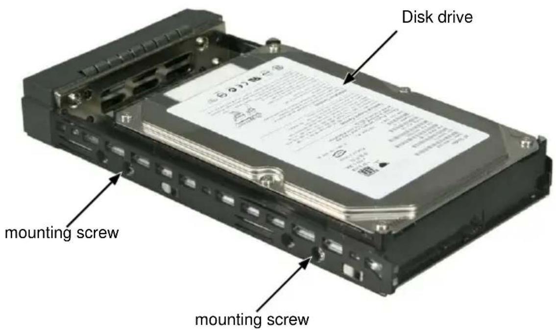
text_image
Disk drive mounting screw mounting screw
Caution
ASUS Storage supports disk drive hot-swapping. To avoid hand contact with an electrical hazard, do not remove more than one drive carrier a time.
This completes disk drive installation. Go to "Task 4: Making Data and Management Connections" on page 9.
Task 4: Making Data and Management Connections
Configuring a Data Path
To establish the data path:
- Make the FC or iSCSI data connections as described in the ASUS Storage DS300F, DS300I User Manual.
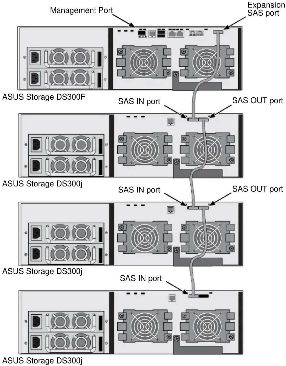
- Connect the SAS Expansion port of the DS300F or DS300I subsystem to the SAS IN port on the I/O module of the first DS300j unit.
See page 10, Figure 7. - Connect the SAS OUT port on the I/O module of the first DS300j unit to the SAS IN port on the I/O module of the second DS300j unit.
- Connect the remaining DS300j units in the same manner.
All SAS ports have SFF-8088 connectors.
Configuring a Management Path
To establish the management path, make the FC or iSCSI management connections as described in the ASUS Storage DS300F, DS300I User Manual.
The RAID controller in the ASUS Storage DS300F or DS300I subsystem also monitors and manages the DS300j units. No additional connections are required for ASUS Storage Management or the CLU.
Direct Management of ASUS Storage
A management connection directly to the ASUS Storage DS300j unit has a serial connection to the Host PC. See “Chapter 3: Management” in the ASUS Storage DS300j User Manual.
Figure 7. Data and management connections with ASUS Storage
This completes data and management connections. Go to "Task 5: Setting Up Serial Cable Connections" on page 11.
Task 5: Setting Up Serial Cable Connections
Serial communication enables the Command Line Interface (CLI) on your PC to monitor and control the ASUS Storage DS300j unit. The product package includes a RJ11-to-DB9 serial data cable.
The CLI is explained in "Chapter 3: Management" on page 17.
Figure 8. The serial connector on the back of the ASUS Storage

text_image
RJ11 Serial ConnectorTo set up a serial cable connection:
- Attach the RJ11 end of the serial data cable to the RJ11 serial connector on the controller.
- Attach the DB9 end of the serial data cable to a serial port on the Host PC or Server.
This completes the serial cable connection. Go to "Task 6: Connecting the Power" on page 12.
Task 6: Connecting the Power
Plug the power cords into the power supplies on the back of the ASUS Storage DS300j unit and switch on the power supplies.
When the power is switched on, the LEDs light up.

Caution
After you turn the power supply switches off, you must wait at least 10 seconds before you turn the power switches on again.
Front Panel LEDs
When boot-up is finished and the ASUS Storage DS300j unit is functioning normally:
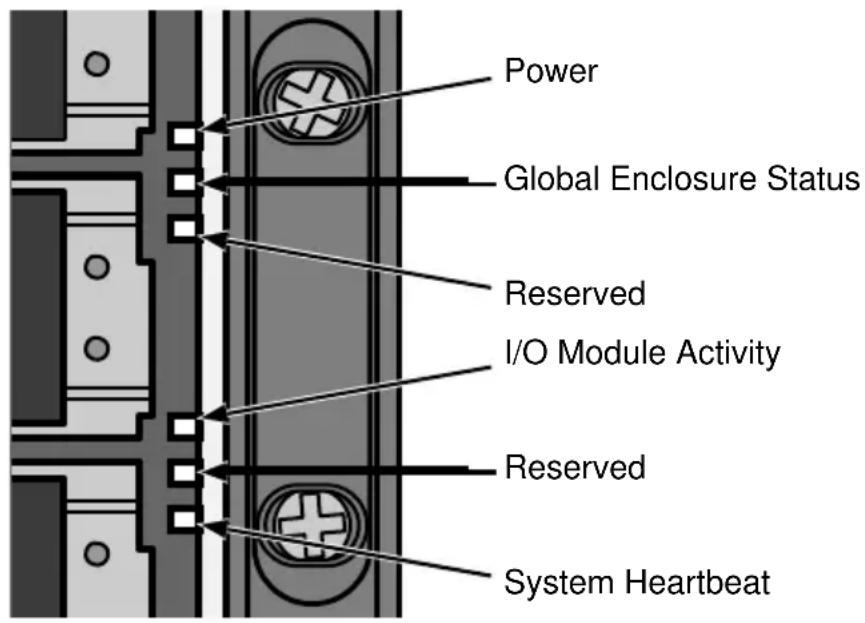
- Power and Global Enclosure Status LEDs display green continuously.
• I/O Module Activity LED flashes green when there is controller activity.
• System Heartbeat LED blinks green once per second.
Figure 9. Front panel LED display
text_image
Power Global Enclosure Status Reserved I/O Module Activity Reserved System HeartbeatI/O Module LEDs
When boot-up is finished and the ASUS Storage subsystem is functioning normally:
- Fan LEDs display green continuously.
- SAS port LEDs flash green when there is activity.
Figure 10. ASUS Storage I/O Module LEDs
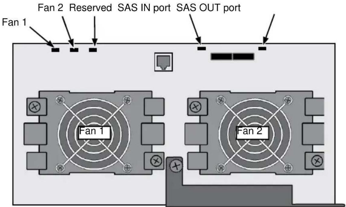
text_image
Fan 1 Fan 2 Reserved SAS IN port SAS OUT port Fan 1 Fan 2Disk Drive LEDs
There are two LEDs on each drive carrier. They report the presence of a disk drive, activity of the drive, and the drive's current condition.
Figure 11. Drive carrier LEDs

text_image
Disk Status Power/ActiviytIf there is a disk drive in the carrier, the Power/Activity LED displays green. If not, the Power/Activity LED remains dark. The Power/Activity LED flashes during drive activity.
The Disk Status LED displays green when a drive is configured.
If there is a disk drive in the carrier, the Power/Activity LED displays green. If not, the Power/Activity LED remains dark. The Power/Activity LED flashes during drive activity.
The Disk Status LED displays green when a drive is configured.
This completes the power and start-up. Go to "Task 7: Setting Up the CLI Connection" on page 14.
Task 7: Setting Up the CLI Connection
The ASUS Storage DS300j unit has a Command Line Interface (CLI) to manage all of its functions via your PC's terminal emulation program, such as Microsoft HyperTerminal. This procedure uses the serial cable connection you made on page 11.
You must use the serial connection to run the CLI for direct management of the ASUS Storage DS300j unit. See “Chapter 3: Management” in the ASUS Storage DS300j User Manual.
To set up a serial connection:
-
Change your terminal emulation program settings to match the following specifications:
-
Bits per second: 115200
- Data bits: 8
- Parity: None
- Stop bits: 1
-
Flow control: none
-
Start your PC's terminal VT100 or ANSI emulation program.
-
Press Enter once to launch the CLI.
When connected and ready, the CLI screen displays:
**************************
ASUS SAS Expander v2.00.0000.xx
**************************
cli>
The cli> prompt on your screen indicates that you have a connection and the CLI is ready to accept commands.
CLI Command Set
The CLI uses the following set of commands:
cable – Specifies the length of cable for optimal signal quality.
enclosure – Displays full information on the VessJBOD enclosure and its components.
factorydefault – Restores factory default settings.
help – Use alone to see the list of commands. Use with a command to see a list of options. Examples: enclosure -help or enclosure -h.
link – Displays the current status of the PHYs (links), error counter, expander and attached SAS addresses.
route – Displays addresses of components through a downstream (expansion) connection.
uptime – Displays the number of days, hours, minutes and seconds since the firmware was loaded (since the VessJBOD was started or restarted).
? – Use alone to see the list of commands. Use with a command to see a list of options. Example: enclosure -?
Command options are NOT case-sensitive.
In the CLI screens, the SAS IN port is called CN#1 and the SAS OUT port is called CN#2. Physical drives in the VessJBOD enclosure are called DSK01 through DSK16.
Contacting TechnicalSupport
ASUS Technical Support provides several support options for ASUS users to access information and updates. We encourage you to use one of our electronic services, which provide product information updates for the most efficient service and support.
If you decide to contact us, please have the following information available:
• Product model and serial number
• BIOS, firmware, and driver version numbers
• A description of the problem / situation
- System configuration information, including: motherboard and CPU type, hard drive model(s), SAS/SATA/ATA/ATAPI drives & devices, and other controllers.
Technical Support Services
ASUS Technical Support http://support.asus.com/