PCM-9563NF-S2A2 - Computers Advantech - Free user manual and instructions
Find the device manual for free PCM-9563NF-S2A2 Advantech in PDF.

User questions about PCM-9563NF-S2A2 Advantech
0 question about this device. Answer the ones you know or ask your own.
Ask a new question about this device
Download the instructions for your Computers in PDF format for free! Find your manual PCM-9563NF-S2A2 - Advantech and take your electronic device back in hand. On this page are published all the documents necessary for the use of your device. PCM-9563NF-S2A2 by Advantech.
USER MANUAL PCM-9563NF-S2A2 Advantech
natural_image
Illustration of four electronic circuit boards with white outlines on a purple background (no text or symbols)PCM-9563
Copyright
The documentation and the software included with this product are copyrighted 2017 by Advantech Co., Ltd. All rights are reserved. Advantech Co., Ltd. reserves the right to make improvements in the products described in this manual at any time without notice. No part of this manual may be reproduced, copied, translated or transmitted in any form or by any means without the prior written permission of Advantech Co., Ltd. Information provided in this manual is intended to be accurate and reliable. However, Advantech Co., Ltd. assumes no responsibility for its use, nor for any infringements of the rights of third parties, which may result from its use.
Acknowledgements
Award is a trademark of Award Software International, Inc.
VIA is a trademark of VIA Technologies, Inc.
IBM, PC/AT, PS/2 and VGA are trademarks of International Business Machines Corporation.
Intel and Pentium are trademarks of Intel Corporation.
Microsoft Windows is a registered trademark of Microsoft Corp.
RTL is a trademark of Realtek Semi-Conductor Co., Ltd.
ESS is a trademark of ESS Technology, Inc.
UMC is a trademark of United Microelectronics Corporation.
SMI is a trademark of Silicon Motion, Inc.
Creative is a trademark of Creative Technology LTD.
CHRONTEL is a trademark of Chrontel Inc.
All other product names or trademarks are properties of their respective owners.
Part No. 2006956300 Edition 1
Printed in China November 2017
Product Warranty (2 years)
Advantech warrants to you, the original purchaser, that each of its products will be free from defects in materials and workmanship for two years from the date of purchase.
This warranty does not apply to any products which have been repaired or altered by persons other than repair personnel authorized by Advantech, or which have been subject to misuse, abuse, accident or improper installation. Advantech assumes no liability under the terms of this warranty as a consequence of such events.
Because of Advantech's high quality-control standards and rigorous testing, most of our customers never need to use our repair service. If an Advantech product is defective, it will be repaired or replaced at no charge during the warranty period. For out-of-warranty repairs, you will be billed according to the cost of replacement materials, service time and freight. Please consult your dealer for more details.
If you think you have a defective product, follow these steps:
- Collect all the information about the problem encountered. (For example, CPU speed, Advantech products used, other hardware and software used, etc.) Note anything abnormal and list any onscreen messages you get when the problem occurs.
- Call your dealer and describe the problem. Please have your manual, product, and any helpful information readily available.
- If your product is diagnosed as defective, obtain an RMA (return merchandise authorization) number from your dealer. This allows us to process your return more quickly.
- Carefully pack the defective product, a fully-completed Repair and Replacement Order Card and a photocopy proof of purchase date (such as your sales receipt) in a shippable container. A product returned without proof of the purchase date is not eligible for warranty service.
- Write the RMA number visibly on the outside of the package and ship it prepaid to your dealer.
Declaration of Conformity
FCC Class B
This equipment has been tested and found to comply with the limits for a Class B digital device, pursuant to part 15 of the FCC Rules. These limits are designed to provide reasonable protection against harmful interference in a residential installation. This equipment generates, uses and can radiate radio frequency energy and, if not installed and used in accordance with the instructions, may cause harmful interference to radio communications. However, there is no guarantee that interference will not occur in a particular installation. If this equipment does cause harmful interference to radio or television reception, which can be determined by turning the equipment off and on, the user is encouraged to try to correct the interference by one or more of the following measures:
■ Reorient or relocate the receiving antenna.
■ Increase the separation between the equipment and receiver.
■ Connect the equipment into an outlet on a circuit different from that to which the receiver is connected.
- Consult the dealer or an experienced radio/TV technician for help.
Technical Support and Assistance
- Visit the Advantech web site at www.advantech.com/support where you can find the latest information about the product.
- Contact your distributor, sales representative, or Advantech's customer service center for technical support if you need additional assistance. Please have the following information ready before you call:
– Product name and serial number
– Description of your peripheral attachments
– Description of your software (operating system, version, application software, etc.)
– A complete description of the problem
– The exact wording of any error messages
Warnings, Cautions and Notes
Warning! Warnings indicate conditions, which if not observed, can cause personal injury!

Caution! Cautions are included to help you avoid damaging hardware or losing data. e.g.

There is a danger of a new battery exploding if it is incorrectly installed. Do not attempt to recharge, force open, or heat the battery. Replace the battery only with the same or equivalent type recommended by the manufacturer. Discard used batteries according to the manufacturer's instructions.
Note! Notes provide optional additional information.

Document Feedback
To assist us in making improvements to this manual, we would welcome comments and constructive criticism. Please send all such - in writing to: support@advantech.com
Packing List
Before setting up the system, check that the items listed below are included and in good condition. If any item does not accord with the table, please contact your dealer immediately.
1 x PCM-9563 SBC
■ 1 x Startup manual
■ 1 x mini jumper pack
9689000002
Ordering Information
Model Number Description
| Model Name CPU | Memory VGA LV | DS HDMI* | DP* eD | DP* Gb | E 1 | SAT | TAIII | mSATA | HD Audio | RS-422/485 | RS-232 | USB 3.0 | USB 2.0 | miniPCIe | M.2 E key | PCI-104 | |||
| PCM-9563N-S1A1E | Intel Coloron N3350 | SODIMM | 1 | 1 | - | - | - | - | 2 | 1 | 1 | V | 2 | 4 | 2 | 6 | 1 | 1 | Yes |
| PCM-9563NF-S2A1E | Intel Pentium N4200 | SODIMM | 1 | 1 | - | - | - | - | 3 | 2 | - | V | 2 | 4 | 2 | 6 | 1 | 1 | Yes |
| PCM-9563NF-S1A1E | Intel Celeron N3350 | SODIMM | 1 | 1 | - | - | - | - | 3 | 2 | - | V | 2 | 4 | 2 | 6 | 1 | 1 | Yes |
* By request
Optional Accessories
Part Number
PCM-10586-9563E
PCM-110-00A3E
PCM-120-00A3E
PCM-200-00A2E
CF-HDD-ADP
TBD
Description
Wiring kit for PCM-9563 Series
1-slot PCI riser card for 5.25" biscuits
2-slot PCI riser card for 5.25" biscuits
PC/104-Plus to PCI bus module
CompactFlash 50-pin to IDE 44-pin adapter
Hearspreader 157.4 x 100 x 24 mm
Safety Instructions
- Read these safety instructions carefully.
- Keep this User Manual for later reference.
- Disconnect this equipment from any AC outlet before cleaning. Use a damp cloth. Do not use liquid or spray detergents for cleaning.
- For plug-in equipment, the power outlet socket must be located near the equipment and must be easily accessible.
- Keep this equipment away from humidity.
- Put this equipment on a reliable surface during installation. Dropping it or letting it fall may cause damage.
- The openings on the enclosure are for air convection. Protect the equipment from overheating. DO NOT COVER THE OPENINGS.
- Make sure the voltage of the power source is correct before connecting the equipment to the power outlet.
- Position the power cord so that people cannot step on it. Do not place anything over the power cord.
- All cautions and warnings on the equipment should be noted.
- If the equipment is not used for a long time, disconnect it from the power source to avoid damage by transient overvoltage.
- Never pour any liquid into an opening. This may cause fire or electrical shock.
- Never open the equipment. For safety reasons, the equipment should be opened only by qualified service personnel.
- If one of the following situations arises, get the equipment checked by service personnel:
■ The power cord or plug is damaged.
- Liquid has penetrated into the equipment.
■ The equipment has been exposed to moisture.
The equipment does not work well, or you cannot get it to work according to the user's manual.
■ The equipment has been dropped and damaged.
■ The equipment has obvious signs of breakage.
-
DO NOT LEAVE THIS EQUIPMENT IN AN ENVIRONMENT WHERE THE STORAGE TEMPERATURE MAY GO BELOW -20^ C ( -4^ F) OR ABOVE 60^ C ( 140^ F). THIS COULD DAMAGE THE EQUIPMENT. THE EQUIPMENT SHOULD BE IN A CONTROLLED ENVIRONMENT.
-
CAUTION: DANGER OF EXPLOSION IF BATTERY IS INCORRECTLY REPLACED. REPLACE ONLY WITH THE SAME OR EQUIVALENT TYPE RECOMMENDED BY THE MANUFACTURER, DISCARD USED BATTERIES ACCORDING TO THE MANUFACTURER'S INSTRUCTIONS.
The sound pressure level at the operator's position according to IEC 704-1:1982 is no more than 70 dB (A).
DISCLAIMER: This set of instructions is given according to IEC 704-1. Advantech disclaims all responsibility for the accuracy of any statements contained herein.
Safety Precaution - Static Electricity
Follow these simple precautions to protect yourself from harm and the products from damage.
To avoid electrical shock, always disconnect the power from your PC chassis before you work on it. Don't touch any components on the CPU card or other cards while the PC is on.
- Disconnect power before making any configuration changes. The sudden rush of power as you connect a jumper or install a card may damage sensitive electronic components.
Contents
Chapter 1 General Information ....1
1.1 Introduction 2
1.2 Product Specifications.... 2
1.3 Chipset 3
1.3.1 Functional Specifications 3
1.3.2 Mechanical Specifications.... 4
1.3.3 Electrical Specifications 4
1.3.4 Environmental Specifications.... 4
Chapter 2 Hardware Installation ....5
2.1 Jumpers 6
2.1.1 Jumper Description 8
2.2 Connectors....9
2.2.1 Connector List....9
2.3 Mechanical 10
2.3.1 Jumper and Connector Location.... 10
Figure 2.1 Jumper and Connector Layout (Component Side)... 10
Figure 2.2 Jumper and Connector Layout (Solder Side) ...... 10
2.3.2 Board Dimensions.... 11
Figure 2.3 Board Dimension Layout (Component Side).... 11
Figure 2.4 Board Dimension Layout (Solder Side) ...... 12
Chapter 3 BIOS Settings......13
3.1 Entering Setup 14
3.1.1 Main Setup.... 14
3.1.2 Advanced BIOS Features Setup.... 15
3.1.3 Chipset Configuration 24
3.1.4 Security 34
3.1.5 Boot.... 35
3.1.6 Save & Exit 36
Chapter 4 Extension I/O Installation....39
Appendix A Pin Assignments 43
Appendix B Optional Extras for PCM-9563 A1 ....75
B.1 PCM-10586-9563E Cable kit for PCM-9563 76
Table B.1: PCM-10586-9562E Cable kit for PCM-9562 A1..... 76
Appendix C System Assignments .....77
C.1 1st MB Memory Map 78
Table C.1: 1st MB memory map 78
C.2 DMA Channel Assignments 78
Table C.2: DMA channel assignments.... 78
C.3 Interrupt Assignments....78
Table C.3: Interrupt assignments.... 78
Table C.4: System I/O Ports 79
Chapter 1
General Information
1.1 Introduction
Intel ^® Pentium N4200 Celeron N3350 & Atom ^TM E3950/E3940/E3930 processor
■ EBX form factor standard, supports PCI-104
■ One SODIMM up to 8G DDR3L 1867MHz
Dual Display: VGA + LVDS(Displayport *) + HDMI * (Displayport)
■ Supports 6 x USB 2.0, 2 x USB 3.0
■ Supports 2 x SATAIII
■ Supports up to 6 x COM (Support Auto flow control)
■ Supports up to 2 x Watchdog Timer
■ Supports up to 3 x Intel Giga Ethernet support
■ Supports Wake-on-LAN, Wake-on-Modem
■ Power off protection and Software I ^2 C API support
1.2 Product Specifications
General
| CPU | Intel Pentium N4200 Celeron N3350 & AtomTM E3950/E3940/E3930 |
| L2 Cache 2MB | |
| System Chipset | |
| BIOS AMI 64 Mbit | |
| System Memory One SODIMM up to 8G DDR3L 1867MHz | |
| Power Management ACPI support | |
| Expansion Interface Supports PCI-104, PCI slot x1, Mini PCIe | |
| Battery Lithium 3 V / 210 mAH |
I/O
| I/O Interface | 1x PS/2, 1x KB/Mouse,1x Reset Button,1x SMBUS, 1x I2C, 1x LTP, 4 x (RS-232), 2 x RS-422/485 |
| USB 6 x USB 2.0 2 x USB 3.0 compliant Ports | |
| Audio ACL888, Line-in, Line-out, Mic-in, speaker out (R/L) | |
| GPIO | 16-bit general purpose |
Ethernet
| Chipset | i210 |
| Speed | 10/100/1000Mbps |
| Interface | 3 (RJ-45 connector through the cable and GbE3 is full version only) |
| Standard | Compliant with IEEE 802.3, IEEE 802.3u, IEEE 802.3x, IEEE 8023y, IEEE 802.ab |
Display
| Controller | Intel® Gen9 Graphic engine |
| VRAM | Shared Memory Architecture up to 224 MB system memory |
| LVDS LCD | Single channel 48-bit LVDS up to 1920 x 1200 |
| VGA | Maximum Resolution up to 1920 x 1200 |
| Dual Independent Display | VGA+ LVDS/eDP*+ HDMI*/DP* |
1.3 Chipset
1.3.1 Functional Specifications
1.3.1.1 Processor
Intel Pentium N4200 Celeron N3350 & Atom™E3950/E3940/E3930 processor 1.1/1.1/1.6/1.6/1.3 GHz
CPU Process: 45nm.
1.3.1.2 Chipset
| Controller Hub | Intel Pentium N4200 Celeron N3350 & AtomTM E3950/E3940/E3930 processor 1.1/1.1/1.6/1.6/1.3 GHz | |
| Memory | DDR3L | 1867MHz |
| Multi Display VGA+ LVDS/eDP*+ HDMI*/DP* | ||
| VGA Memory Up to 224 MB of dynamic video memory allocation | ||
| Display | VGA: Supports QXGA Up to 1920 x 1200LVDS: Single channel 48-bit LVDS up to 1920 x 1200 | |
| Internal Graphics Features | 3D HW Acceleration: DirectX* 12.3/12,4K Decode fo rHEVC4, H.264, VP8;4K Encode forH.264, VP8 | |
1.3.1.3 Others
| Ethernet | |
| Chipset | GbE 1: Intel i210GbE 2: Intel i210GbE 3: Intel i210 |
| IEEE Compliant | Compliant with IEEE 802.3, IEEE 802.3u, IEEE 802.3x, IEEE 8023y, IEEE 802.ab |
| Disable LAN through BIOS Yes | |
| Driver Support Win 10, Android, Linux, QNX | |
| Audio | |
| Codec HD Audio, ALC888 Codec | |
| Connector | Line in, Line out, Mic in, Speak out (R/L, 8 Ohm 1W/4Ohm 2W) |
| Hardware Monitor | |
| Super I/O | LPC I/O for onboard alarm |
| SCH3106 | |
| Fan | 1. Smart FAN Support.2. Programmable automatic fan monitor based on temperature.3. 2 pin connector for LED indication when fan fail or system abnormal.4. System FAN Power Connector x 15. Reserve CPU FAN Power Connector x 1Pin2: +12 VPin3: Fan speed signal input |
| Temperature | CPU Temperature |
| Voltage | 3.3 V,+5 V, +12 V, Vcore |
| PCI Compliant | |
| Chipset | follow PCIe bridge XIO2001IZGU |
1.3.2 Mechanical Specifications
1.3.2.1 Dimensions
203mm(L*146mm(W) mm (8" x 5.75 inches)
1.3.2.2 Height
top side 19mm, PCB 1.6mm, bottom side 6.8mm, total 27.4mm
1.3.2.3 Weight
700 g (1.54 lb) (with heatsink) (reference weight of total package)
1.3.3 Electrical Specifications
1.3.3.1 Power Supply Voltage
Power Type
AT/ATX
■ Power Supply Voltage
ATX: 12 V ± 10%
AT: 12 V ±10% only
1.3.3.2 Power Consumption
Power Consumption (Typical)
PCM-9563E-S7A1E with E3950:0.64@12V(7.68W)
Power Consumption (Max, test in HCT)
PCM-9563E-S7A1E with E3950:1.03A@12V(12.38W)
1.3.3.3 RTC Battery
■ Typical Voltage: 3.0 V
■ Normal discharge capacity: 210 mAh
1.3.4 Environmental Specifications
1.3.4.1 Operating Temperature
■ Operating temperature: 0 \~ 60°C (32\~140°F)
1.3.4.2 Operating Humidity
- Operating Humidity: 0% \~ 90% Relative Humidity, non-condensing
1.3.4.3 Storage Temperature
Standard products (0\~60°C)
■ Storage temperature: -40\~85°C
1.3.4.4 Storage Relative Temperature
Standard products (0\~60°C)
■ Relative humidity: 95% @ 60°C
Phoenix products (-20\~80°C)
■ Relative humidity: 95% @ 60°C
Platinum Phoenix products (-40\~85°C)
■ Relative humidity: 95% @ 60°C
Chapter 2
Hardware Installation
This chapter explains the setup procedures of the PCM-9563 A1 hardware, including instructions on setting jumpers and connecting peripherals, switches, indicators and mechanical drawings. Be sure to read all safety precautions before you begin the installation procedure.
2.1 Jumpers
J1 Clear CMOS
Part Number 1653003101
Footprint HD_3x1P_79_D
Description PIN HEADER 3x1P 2.0mm 180D(M) DIP 2000-13 WS
Setting Function
(1-2)* Normal
(2-3) Clear COMS

J2 Auto Power On Setting
Part Number 1653002101
Footprint HD_2x1P_79_D
Description PIN HEADER 2*1P 180D(M)SQUARE 2.0mm DIP W/O Pb
Setting Function
NC Power Button for Power On
(1-2)* Auto Power On

J3 PCI104 VIO Setting
Part Number 1653003101
Footprint HD_3x1P_79_D
Description PIN HEADER 3x1P 2.0mm 180D(M) DIP 2000-13 WS
Setting Function
(1-2) +5V
(2-3)* +3.3V

J4 LCD Power
Part Number 1653003260
Footprint HD_3x2P_79
Description PIN HEADER 3x2P 2.0mm 180D(M) SMD 21N22050
Setting Function
(1-3)* +3.3V
(3-5) +5V
(3-4) +12V

J5 LVDS VCON Setting
Part Number 1653000014
Footprint HD_2x2P_79
Description PIN HEADER 2x2P 2.00mm 180D(M) SMD 21N22050
Setting Function
(1-2)* 3.3V High for VCON on LVDS
(1-3) Low for VCON on LVDS

J6 COM5 RS422/485 Setting
Part Number 1653003101
Footprint HD_3x1P_79_D
Description PIN HEADER 3x1P 2.0mm 180D(M) DIP 2000-13 WS
Setting Function
(1-2)* RS485
(1-3) RS422

J7 COM6 RS422/485 Setting
Part Number 1653003101
Footprint HD_3x1P_79_D
Description PIN HEADER 3x1P 2.0mm 180D(M) DIP 2000-13 WS
Setting Function
(1-2)* RS485
(1-3) RS422

| J8 PCI VIO Setting | |
| Part Number 1653003101 | |
| Footprint HD_3x1P_79_D | |
| Description | PIN HEADER 3x1P 2.0mm 180D(M) DIP 2000-13 WS |
| Setting Function | |
| (1-2) +5V | |
| (2-3)* +3.3V | |

2.1.1 Jumper Description
Cards can be configured by setting jumpers. A jumper is a metal bridge used to close an electric circuit. It consists of two metal pins and a small metal clip (often protected by a plastic cover) that slides over the pins to connect them. To close a jumper, you connect the pins with the clip. To open a jumper, you remove the clip. Sometimes a jumper will have three pins, labeled 1, 2 and 3. In this case you would connect either pins 1 and 2, or 2 and 3.


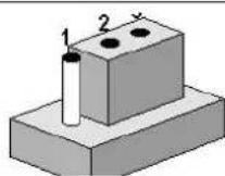
The jumper settings are schematically depicted in this manual as follows.


A pair of needle-nose pliers may be helpful when working with jumpers. If you have any doubts about the best hardware configuration for your application, contact your local distributor or sales representative before you make any changes.
Warning! To avoid damaging the computer, always turn off the power supply before setting jumpers to clear CMOS. Before turning on the power supply, set the jumper back to 3.0 V Battery On.

2.2 Connectors
Onboard connectors link the PCM-9563 to external devices such as hard disk drives, a keyboard, or floppy drives. The table below lists the function of each of the connectors.
2.2.1 Connector List
| CN1 | 12V Power Input |
| CN3 | Standby Power Input |
| CN4 | 5V power output |
| CN5 | Battery |
| CN6 | SODIMMDDR3RVS_204 |
| CN8 | Power Switch |
| CN9 | Reset |
| CN10 | Audio |
| CN11 | LAN1 |
| CN12 | LAN1/2 LED |
| CN13 | LAN2 |
| CN14 | LAN3 |
| CN15 | PCI-104 |
| CN16 | SIM |
| CN17 | Mini PCIE |
| CN18 | SATA |
| CN19 | SATA |
| CN20 | mSATA |
| CN21 | M.2 E Key |
| CN22 | COM1/COM2 |
| CN23 | COM3/COM4 |
| CN24 | COM5/COM6 |
| CN25 | Inverter Power Output |
| CN26 | 48 bits LVDS Panel |
| CN27 | VGA |
| CN28 | HDMI |
| CN29 | eDP |
| CN30 | Internal USB |
| CN31 | Internal USB |
| CN32 | Internal USB |
| CN33 | Internal USB 3.0 |
| CN34 | LPT |
| CN35 | PS2 |
| CN36 | I2C |
| CN37 | SMBus |
| CN38 | GPIO 0-7 |
| CN39 | GPIO 8-15 |
| CN40 | System Fan |
| CN45 | PCI Slot |
| CN46 | PWR/HD/LAN3 LED |
| CN48 | PCI-104 -12V Input |
2.3 Mechanical
2.3.1 Jumper and Connector Location
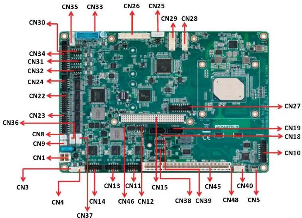
text_image
CN30 CN35 CN33 CN26 CN25 CN29 CN28 CN34 CN31 CN32 CN24 CN22 CN23 CN36 CN8 CN9 CN1 CN3 CN4 CN13 CN11 CN15 CN45 CN40 CN37 CN4 CN14 CN46 CN12 CN38 CN39 CN48 CN5Figure 2.1 Jumper and Connector Layout (Component Side)

text_image
CN17 CN20 CN16 CN21 CN6Figure 2.2 Jumper and Connector Layout (Solder Side)
2.3.2 Board Dimensions
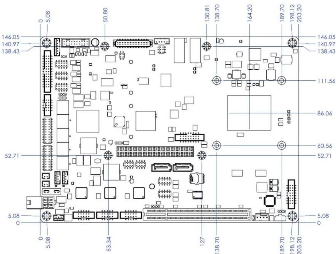
text_image
146.05 140.97 138.43 50.80 130.81 138.70 164.20 189.70 198.12 203.20 146.05 140.97 138.43 111.56 86.06 52.71 60.56 52.71 5.08 0 5.08 53.34 127 138.70 189.70 198.12 203.20 5.08 0Figure 2.3 Board Dimension Layout (Component Side)
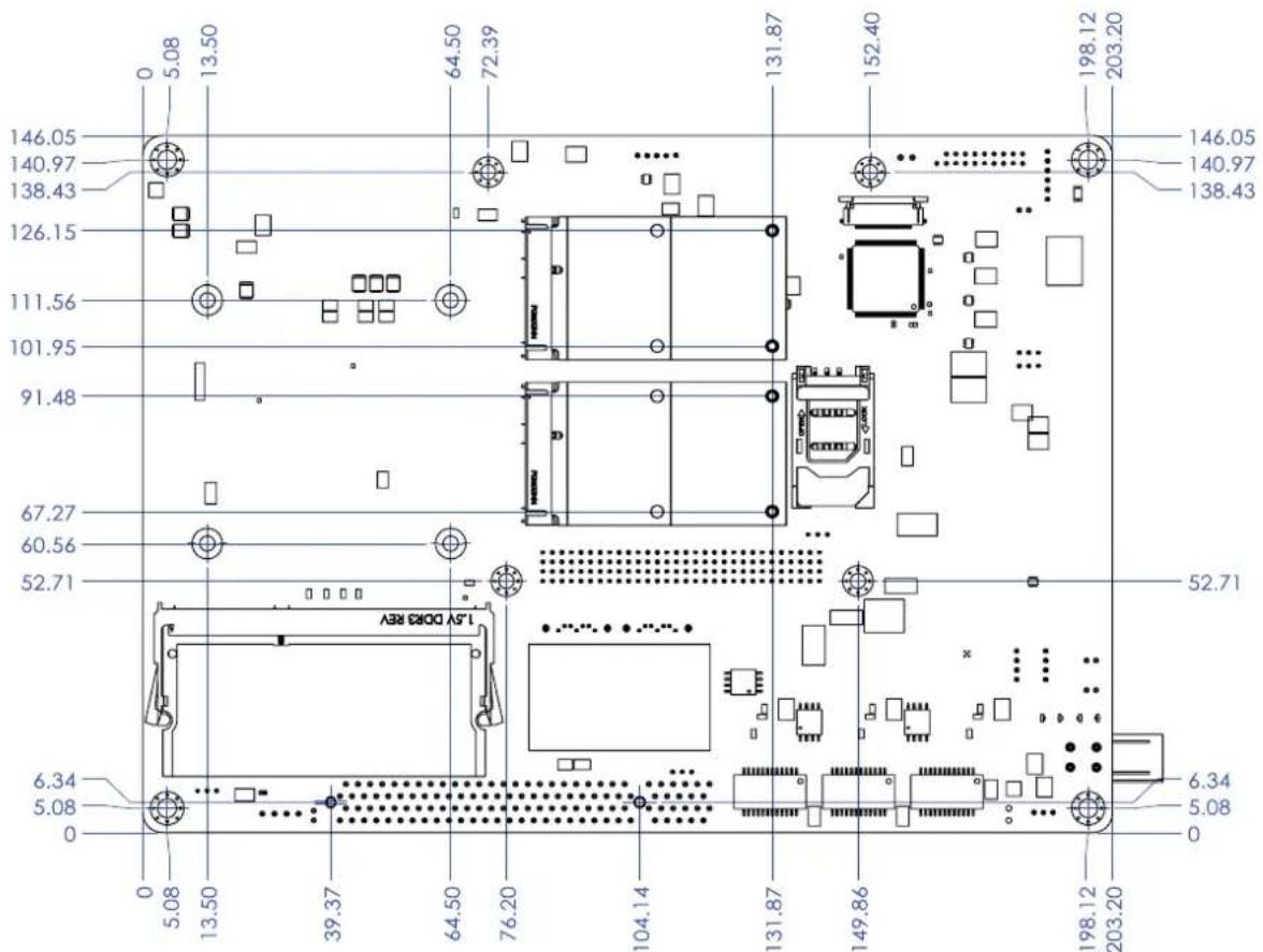
text_image
146.05 140.97 138.43 126.15 111.56 101.95 91.48 67.27 60.56 52.71 15V DORE REV 6.34 5.08 0 0 5.08 13.50 39.37 64.50 76.20 104.14 131.87 152.40 198.12 203.20 146.05 140.97 138.43 131.87 152.40 198.12 203.20 52.71 6.34 5.08 0Figure 2.4 Board Dimension Layout (Solder Side)
Chapter 3
BIOS Settings
AMIBIOS has been integrated into many motherboards for over a decade. With the AMIBIOS Setup program, you can modify BIOS settings and control the various system features. This chapter describes the basic navigation of the PCM-9563 BIOS setup screens.
| Aptio Setup Utility - Copyright (C) 2017 American Megatrends, Inc. Main Advanced Chipset Security Boot Save & Exit | |
| BIOS Information BIOS Vendor Core Version Compliance Project Version Build Date and Time Access Level | American Megatrends 5.0.1.2 0.32 x64 UEFI 2.5; PI 1.4 PCM 95630000060X028 07/21/2017 13:13:27 Administrator |
| System Language | [English] |
| System Date | [Sat 08/26/2017] |
| System Time | [22:01:39] |
| Power Type | AT |
| Choose the system default language | |
| ++: Select Screen ↑↓: Select Item Enter: Select +/-: Change Opt. F1: General Help F2: Previous Values F3: Optimized Defaults F4: Save & Exit ESC: Exit | |
| Version 2.18.1263. Copyright (C) 2017 American Megatrends, Inc. | |
AMI's BIOS ROM has a built-in Setup program that allows users to modify the basic system configuration. This information is stored in battery-backed CMOS so it retains the Setup information when the power is turned off.
3.1 Entering Setup
Turn on the computer and check for the “patch” code. If there is a number assigned to the patch code, it means that the BIOS supports your CPU. If there is no number assigned to the patch code, please contact an Advantech application engineer to obtain an up-to-date patch code file. This will ensure that your CPU’s system status is valid. After ensuring that you have a number assigned to the patch code, press and you will immediately be allowed to enter Setup.
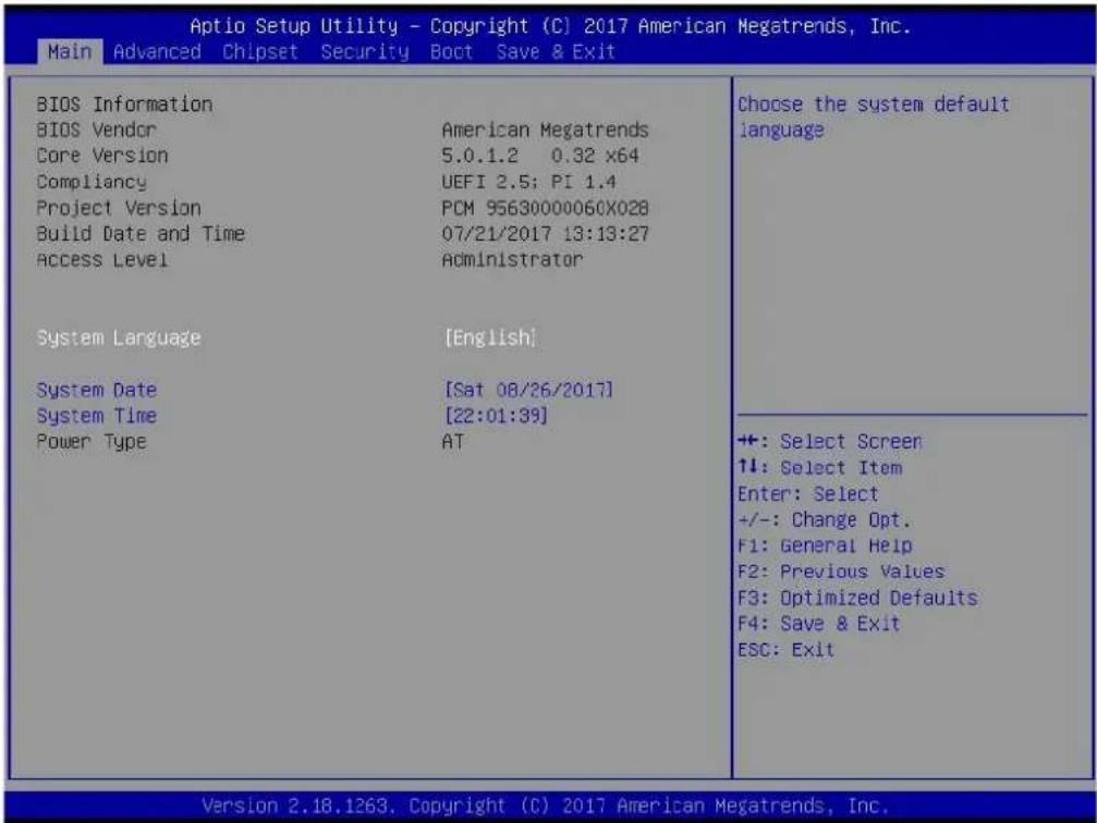
3.1.1 Main Setup
When you first enter the BIOS Setup Utility, you will enter the Main setup screen. You can always return to the Main setup screen by selecting the Main tab. There are two Main Setup options. They are described in this section. The Main BIOS Setup screen is shown below.
text_image
Aptio Setup Utility - Copyright (C) 2017 American Megatrends, Inc. Main Advanced Chipset Security Boot Save & Exit BIOS Information BIOS Vendor Core Version Compliancy Project Version Build Date and Time Access Level System Language System Date System Time Power Type American Megatrends 5.0.1.2 0.32 x64 UEFI 2.5; PI 1.4 PCM 95630000060X028 07/21/2017 13:13:27 Administrator [English] [Sat 08/26/2017] [22:01:39] AT Choose the system default language ++: Select Screen ↑↓: Select Item Enter: Select +/-: Change Opt. F1: General Help F2: Previous Values F3: Optimized Defaults F4: Save & Exit ESC: Exit Version 2.18.1263. Copyright (C) 2017 American Megatrends, Inc.The Main BIOS setup screen has two main frames. The left frame displays all the options that can be configured. Grayed-out options cannot be configured; options in blue can. The right frame displays the key legend.
Above the key legend is an area reserved for a text message. When an option is selected in the left frame, it is highlighted in white. Often a text message will accompany it.
■ System time / System date
Use this option to change the system time and date. Highlight System Time or System Date using the
3.1.2 Advanced BIOS Features Setup
Select the Advanced tab from the PCM-9563 setup screen to enter the Advanced BIOS Setup screen. You can select any of the items in the left frame of the screen, such as CPU Configuration, to go to the sub menu for that item. You can display an Advanced BIOS Setup option by highlighting it using the

text_image
Aptio Setup Utility - Copyright (C) 2017 American Megatrends, Inc. Main Advanced Chipset Security Boot Save & Exit ► ACPI Settings ► SCH3106 Super IO Configuration ► Embedded Controller Configuration ► S5 RTC Wake Settings ► Serial Port Console Redirection ► CFU Configuration ► Network Stack Configuration ► CSM Configuration ► USB Configuration ► Security Configuration Provides Health Status for the Drivers/Controllers +: Select Screen ↑↓: Select Item Enter: Select +/-: Change Opt. F1: General Help F2: Previous Values F3: Optimized Defaults F4: Save & Exit ESC: Exit Version 2.18.1263. Copyright (C) 2017 American Megatrends, Inc.3.1.2.1 ACPI Settings

text_image
Aptio Setup Utility - Copyright (C) 2017 American Megatrends, Inc. Advanced ACPI Settings Enable ACPI Auto Configuration [Disabled] Enable Hibernation [Enabled] ACPI Sleep State [S3 (Suspend to RAM)] Lock Legacy Resources [Disabled] Enables or Disables BIOS ACPI Auto Configuration. +: Select Screen ↑↓: Select Item Enter: Select +/-: Change Opt. F1: General Help F2: Previous Values F3: Optimized Defaults F4: Save & Exit ESC: Exit Version 2.18.1263. Copyright (C) 2017 American Megatrends, Inc.■ Enable ACPI Auto Configuration
Enable or disable BIOS ACPI auto configuration.
■ Enable Hibernation
Enables or Disables System ability to Hibernate (OS/S4 Sleep State). This option may be not effective with some OS.
ACPI Sleep State
Select the highest ACPI sleep state the system will enter when the SUSPEND button is pressed.
■ Lock Legacy Resources
Enables or Disables Lock of Legacy Resources
3.1.2.2 SCH3106 Super IO Configuration

text_image
Aptio Setup Utility - Copyright (C) 2017 American Megatrends, Inc. Advanced SCH3106 Super IO Configuration Super IO Chip SCH3106 ► Serial Port 1 Configuration ► Serial Port 2 Configuration ► Serial Port 3 Configuration ► Serial Port 4 Configuration ► Serial Port 5 Configuration ► Serial Port 6 Configuration ► Parallel Port Configuration Set Parameters of Serial Port 1 (COMA) ++ : Select Screen 11: Select Item Enter: Select +/-: Change Opt. F1: General Help F2: Previous Values F3: Optimized Defaults F4: Save & Exit ESC: Exit Version 2.18.1263. Copyright (C) 2017 American Megatrends, Inc.Serial Port 1 Configuration
Set Parameters of Serial Port 1 (COMA).
Serial Port 2 Configuration
Set Parameters of Serial Port 2 (COMB).
Serial Port 3 Configuration
Set Parameters of Serial Port 3 (COMC).
Serial Port 4 Configuration
Set Parameters of Serial Port 4 (COMD).
Serial Port 5 Configuration
Set Parameters of Serial Port 5 (COME).
Serial Port 6 Configuration
Set Parameters of Serial Port 6 (COMF).
Parallel Port Configuration
Set Parameters of Parallel Port (LPT/LPTE).
3.1.2.3 Embedded Controller Configuration

text_image
Aptio Setup Utility - Copyright (C) 2017 American Megatrends, Inc. Advanced EC Firmware Version I2BA7X000C EC Hardware Monitor CPU Temperature : +32°C/ +89°F SYSTEM FAN Speed : N/A +VBAT : +2.370 V +5VSB : +4.396 V +12V : +11.775 V Vcore : +0.747 V Backlight Enable Polarity [Native] 1st LVDS Backlight Control [PWM] Power Saving Mode [Normal] Deep Sleep delay time 10 Watch Dog Timer [Disabled] Switch Backlight Enable Polarity for Native or Invert. Native:High active. Invert:Low active. +: Select Screen ↓: Select Item Enter: Select +/-: Change Opt. F1: General Help F2: Previous Values F3: Optimized Defaults F4: Save & Exit ESC: Exit Version 2.18.1263. Copyright (C) 2017 American Megatrends, Inc.■ EC Hardware Monitor
This page displays all information about system Temperature/Voltage/Current.
■ Backlight Enable Polarity
This item allows users to set backlight mode.
■ 1st LVDS Backlight control
This item allows users to switch Backlight Control for PWM or DC mode.
Power Saving Mode
This item allows users to set board's power saving mode when off.
■ Watch Dog Timer
This item allows users to select EC watchdog timer.
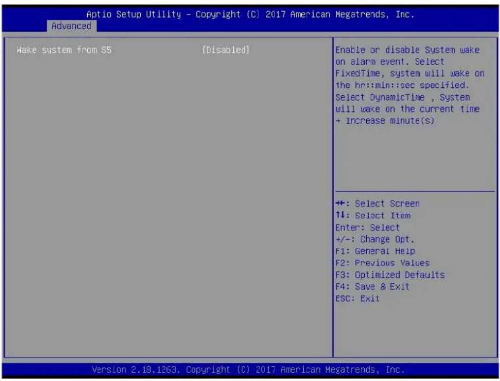
3.1.2.4 S5 RTC Wake Settings
text_image
Aptio Setup Utility - Copyright (C) 2017 American Megatrends, Inc. Advanced Wake system from S5 [Disabled] Enable or disable System wake on alarm event. Select FixedTime, system will wake on the hr::min::sec specified. Select DynamicTime , System will wake on the current time + Increase minute(s) +: Select Screen ↑↓: Select Item Enter: Select +/-: Change Opt. F1: General Help F2: Previous Values F3: Optimized Defaults F4: Save & Exit ESC: Exit Version 2.18.1263. Copyright (C) 2017 American Megatrends, Inc.■ Wake system from S5
Enable or disable System wake on alarm event. Select FixedTime, system will wake on the hr::min::sec specified.
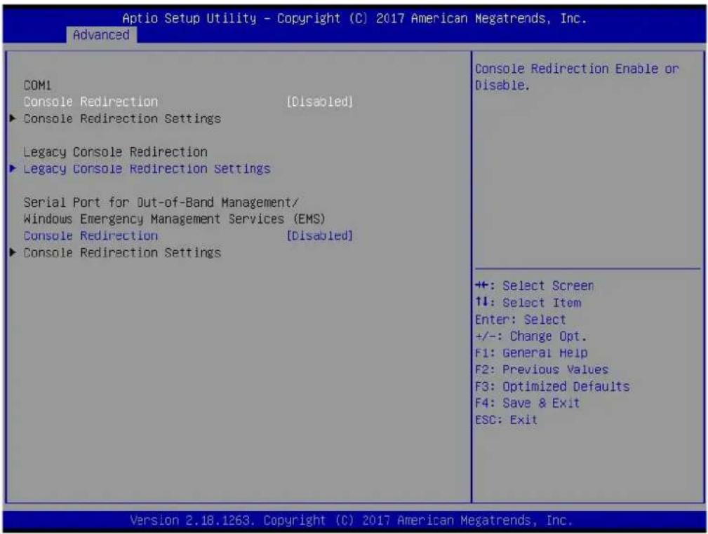
3.1.2.5 Serial Port Console Redirection
text_image
Aptio Setup Utility - Copyright (C) 2017 American Megatrends, Inc. Advanced COM1 Console Redirection [Disabled] ► Console Redirection Settings Legacy Console Redirection ► Legacy Console Redirection Settings Serial Port for Out-of-Band Management/ Windows Emergency Management Services (EMS) Console Redirection [Disabled] ► Console Redirection Settings Console Redirection Enable or Disable. ++: Select Screen ↑↓: Select Item Enter: Select +/-: Change Opt. F1: General Help F2: Previous Values F3: Optimized Defaults F4: Save & Exit ESC: Exit Version 2.18.1263. Copyright (C) 2017 American Megatrends, Inc.■ Console Redirection
This item allows users to enable or disable console redirection for Microsoft Windows Emergency Management Services (EMS).
■ Console Redirection
This item allows users to configuration console redirection detail settings.
■ Legacy Console Redirection
This item allows users to configure the legacy serial redirection port.
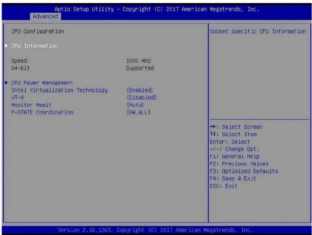
3.1.2.6 CPU Configuration
text_image
Aptio Setup Utility - Copyright (C) 2017 American Megatrends, Inc. Advanced CPU Configuration ► CPU Information Speed 1600 MHz 54-bit Supported ► CPU Power Management Intel Virtualization Technology [Enabled] VT-d [Disabled] Monitor Mwait [Auto] P-STATE Coordination [HW_ALL] Socket specific CPU Information +: Select Screen ↑↓: Select Item Enter: Select +/-: Change Opt. F1: General Help F2: Previous Values F3: Optimized Defaults F4: Save & Exit ESC: Exit Version 2.18.1263, Copyright (C) 2017 American Megatrends, Inc.■ CPU Power Management
CPU Power Management options.
Intel Virtualization Technology
When enabled, a VMM can utilize the additional hardware capabilities provided by Vanderpool Technology.
VT-d
Enable/Disable CPU VT-d.
Monitor Mwait
Enable/Disable Monitor Mwait.
■ P-STATE Coordination
Change P-STATE Coordination type.
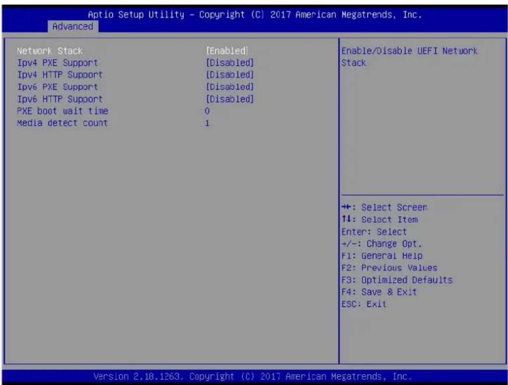
3.1.2.7 Network Stack Configuration
text_image
Aptio Setup Utility - Copyright (C) 2017 American Megatrends, Inc. Advanced Network Stack [Enabled] IPv4 PXE Support [Disabled] IPv4 HTTP Support [Disabled] IPv6 PXE Support [Disabled] IPv6 HTTP Support [Disabled] PXE boot wait time 0 Media detect count 1 Enable/Disable UEFI Network Stack +: Select Screen ↑↓: Select Item Enter: Select +/-: Change Opt. F1: General Help F2: Previous Values F3: Optimized Defaults F4: Save & Exit ESC: Exit Version 2.18.1263. Copyright (C) 2017 American Megatrends, Inc.Network Stack
Enable/Disable UEFI Network Stack.
■ lpv4 PXE Support
Enable lpv4 PXE Boot Support. If disabled IPV4 PXE boot option will not be created.
■ lpv4 HTTP Support
Enables lpv4 HTTP boot support. If disabled IPV4 HTTP boot option will not be created.
■ PXE boot wait time
Wait time to press ESC key to abort the PXE boot.
■ Media detect count
Number of times presence of media will be checked.
3.1.2.8 CSM Configuration

text_image
Aptio Setup Utility - Copyright (C) 2017 American Megatrends, Inc. Advanced Compatibility Support Module Configuration CSM Support [Enabled] CSM16 Module Version 07.79 GateA20 Active [Lupon Request] INT19 Trap Response [Immediate] Boot option filter [LEFI only] Option ROM execution Network [LEFI] Storage [LEFI] Video [LEFI] Other PCI devices [LEFI] Enable/Disable CSM Support. +: Select Screen ↑↓: Select Item Enter: Select +/-: Change Opt. F1: General Help F2: Previous Values F3: Optimized Defaults F4: Save & Exit ESC: Exit Version 2.18.1263. Copyright (C) 2017 American Megatrends, Inc.CSM Support
Enable/Disable CSM Support.
GateA20 Active
UPON REQUEST - GA20 can be disabled using BIOS services. ALWAYS - do not allow disabling GA20; this option is useful when any RT code is executed above 1MB.
■ INT19 Trap Response
BIOS reaction on INT19 trapping by Option ROM: IMMEDIATE - execute the trap right away; POSTPONED - execute the trap during legacy boot.
■ Boot option filter
This option controls Legacy/UEFI ROMs priority.
Network
Controls the execution of UEFI and Legacy PXE OpROM.
Storage
Controls the execution of UEFI and Legacy Storage OpROM.
Video
Controls the execution of UEFI and Legacy Video OpROM.
■ Other PCI devices
Determines OpROM execution policy for devices other than Network, Storage, or Video.
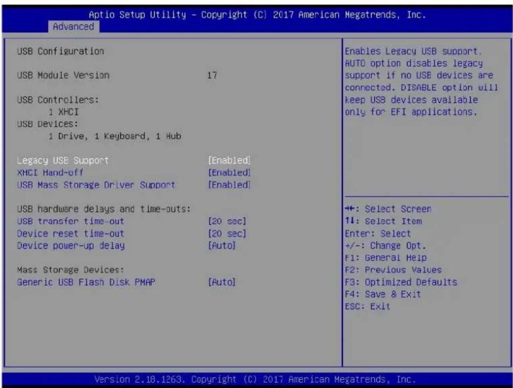
3.1.2.9 USB Configuration
text_image
Aptio Setup Utility - Copyright (C) 2017 American Megatrends, Inc. Advanced USB Configuration USB Module Version 17 USB Controllers: 1 XHCI USB Devices: 1 Drive, 1 Keyboard, 1 Hub Legacy USB Support [Enabled] XHCI Hand-off [Enabled] USB Mass Storage Driver Support [Enabled] USB hardware delays and time-outs: USB transfer time-out [20 sec] Device reset time-out [20 sec] Device power-up delay [Auto] Mass Storage Devices: Generic USB Flash Disk PMAP [Auto] Enables Legacy USB support. AUTO option disables legacy support if no USB devices are connected. DISABLE option will keep USB devices available only for EFI applications. +: Select Screen 1↓: Select Item Enter: Select +/-: Change Opt. F1: General Help F2: Previous Values F3: Optimized Defaults F4: Save & Exit ESC: Exit Version 2.18.1263. Copyright (C) 2017 American Megatrends, Inc.■ Legacy USB Support
Enables Legacy USB support. AUTO option disables legacy support if no USB devices are connected. DISABLE option will keep USB devices available only for EFI applications.
XHCI Hand-off
This is a workaround for OSes without XHCI hand-off support. The XHCI ownership change should be claimed by XHCI driver.
USB Mass Storage Driver Support
Enable/Disable USB Mass Storage Driver Support.
USB transfer time-out
Time-out value for control, Bulk, and interrupt transfers.
■ Device reset time-out
USB mass storage device start unit command time-out.
■ Device power-up delay
Maximum time the device will take before it properly reports itself to the Host Controller. 'Auto' uses default value: for a Root port it is 100 ms, for a Hub port the delay is taken from Hub descriptor.
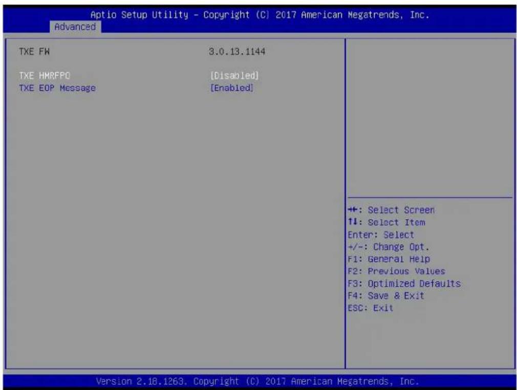
3.1.2.10 Security Configuration
text_image
Aptio Setup Utility - Copyright (C) 2017 American Megatrends, Inc. Advanced TXE FW 3.0.13.1144 TXE HMRFPO [Disabled] TXE EOP Message [Enabled] +: Select Screen ↑↓: Select Item Enter: Select +/-: Change Opt. F1: General Help F2: Previous Values F3: Optimized Defaults F4: Save & Exit ESC: Exit Version 2.18.1263. Copyright (C) 2017 American Megatrends, Inc.■ TXE HMRFPO Disable
■ TXE EOP Message
Send EOP Message Before Enter OS
3.1.3 Chipset Configuration

text_image
Aptio Setup Utility - Copyright (C) 2017 American Megatrends, Inc. Main Advanced Chipset Security Boot Save & Exit North Bridge South Bridge Uncore Configuration South Cluster Configuration North Bridge Parameters +: Select Screen ↑↓: Select Item Enter: Select +/-: Change Opt. F1: General Help F2: Previous Values F3: Optimized Defaults F4: Save & Exit ESC: Exit Version 2.18.1263. Copyright (C) 2017 American Megatrends, Inc.North Bridge
Details for North Bridge items.
■ South Bridge
Details for South Bridge items.
■ Uncore Configuration
Details for Uncore Configuration.
■ South Cluster Configuration
Details for South Cluster Configuration.
3.1.3.1 North Bridge

text_image
Aptio Setup Utility - Copyright (C) 2017 American Megatrends, Inc. Chipset Memory Information Total Memory 8192 MB (DDR3L) Memory Slot 1 8192 MB (DDR3L) Max TOLUD [2 GB] Maximum Value of TOLUD. +: Select Screen ↑↓: Select Item Enter: Select +/-: Change Opt. F1: General Help F2: Previous Values F3: Optimized Defaults F4: Save & Exit ESC: Exit Version 2.18.1263, Copyright (C) 2017 American Megatrends, Inc.■ Max TOLUD Maximum Value of TOLUD.
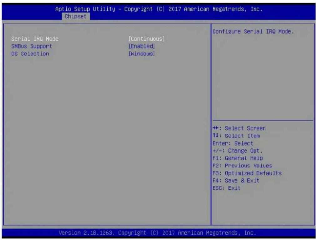
3.1.3.2 South Bridge
text_image
Aptio Setup Utility - Copyright (C) 2017 American Megatrends, Inc. Chipset Serial IRQ Mode [Continuous] SMBus Support [Enabled] OS Selection [Windows] Configure Serial IRQ Mode. +: Select Screen ↑↓: Select Item Enter: Select +/-: Change Opt. F1: General Help F2: Previous Values F3: Optimized Defaults F4: Save & Exit ESC: Exit Version 2.18.1263, Copyright (C) 2017 American Megatrends, Inc.Serial IRQ Mode
Configure Serial IRQ Mode.
■ SMBus Support
Enable/Disable SMBus Support.
OS Selection
Select the target OS.
3.1.3.3 Uncore Configuration
text_image
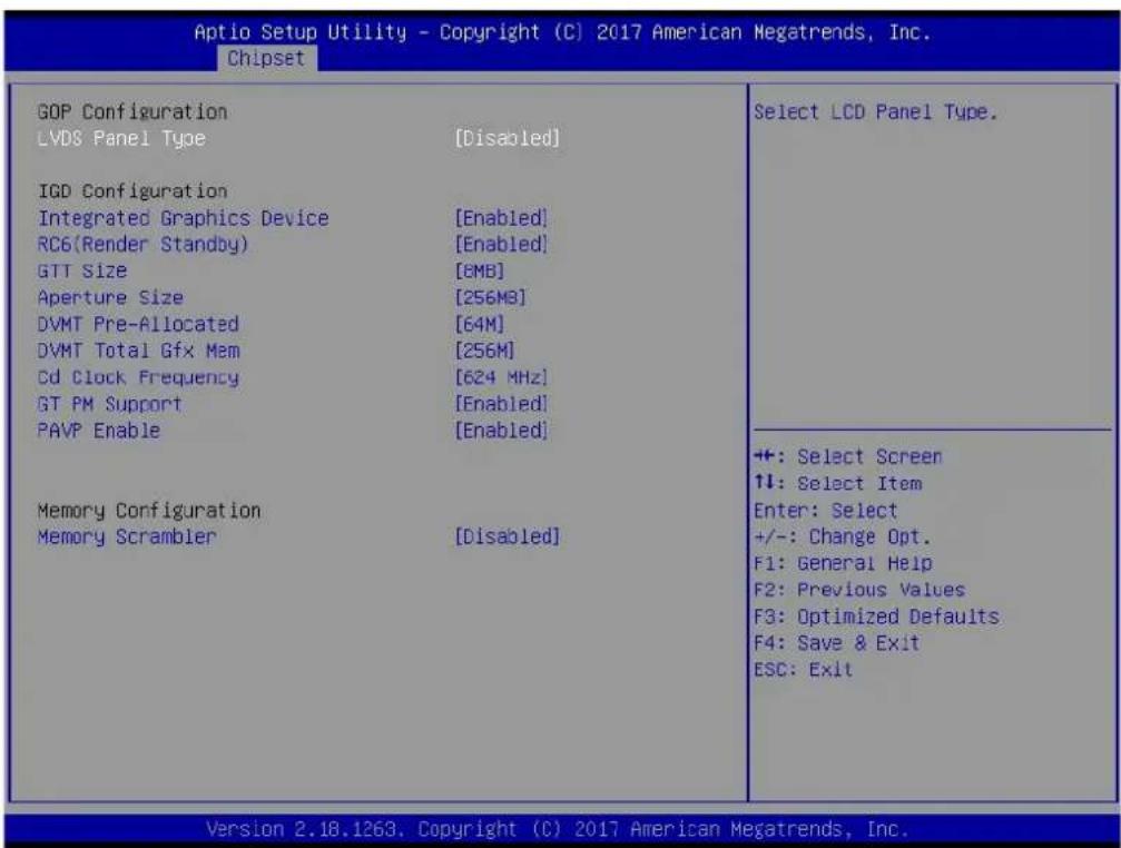
Aptio Setup Utility - Copyright (C) 2017 American Megatrends, Inc. Chipset GOP Configuration LVDS Panel Type [Disabled] IGD Configuration Integrated Graphics Device [Enabled] RC6(Render Standby) [Enabled] GTT Size [6MB] Aperture Size [256MB] DVMT Pre-Allocated [64M] DVMT Total Gfx Mem [256M] Cd Clock Frequency [624 MHz] GT PM Support [Enabled] PAVP Enable [Enabled] Memory Configuration Memory Scrambler [Disabled] Select LCD Panel Type. +: Select Screen ↑↓: Select Item Enter: Select +/-: Change Opt. F1: General Help F2: Previous Values F3: Optimized Defaults F4: Save & Exit ESC: Exit Version 2.18.1263. Copyright (C) 2017 American Megatrends, Inc.LVDS Panel Type
Select LCD Panel Type.
■ Integrated Graphics Device
Enable: Enable Integrated Graphics Device (IGD) when selected as the Primary Video Adaptor. Disable : Always disable IGD.
RC6 Render Standby)
Check to enable render standby support.
GTT Size
Select the GTT Size
Aperture Size
Select the Aperture Size.
DVMT Pre-Allocated
Select DVMT 5.0 Pre-Allocated (Fixed) Graphics Memory size used by the Internal Graphics Device.
DVMT Total Gfx Mem
Select DVMT 5.0 Total Graphic Memory size used by the Internal Graphics Device.
Cd Clock Frequency
Select the highest Cd Clock frequency supported by the platform.
GT PM Support
Enable/Disable GT PM Support.
PAVP Enable
Enable/Disable PAVP.
■ Memory Scrambler
Enable/Disable Memory Scrambler support.
3.1.3.4 South Cluster Configuration
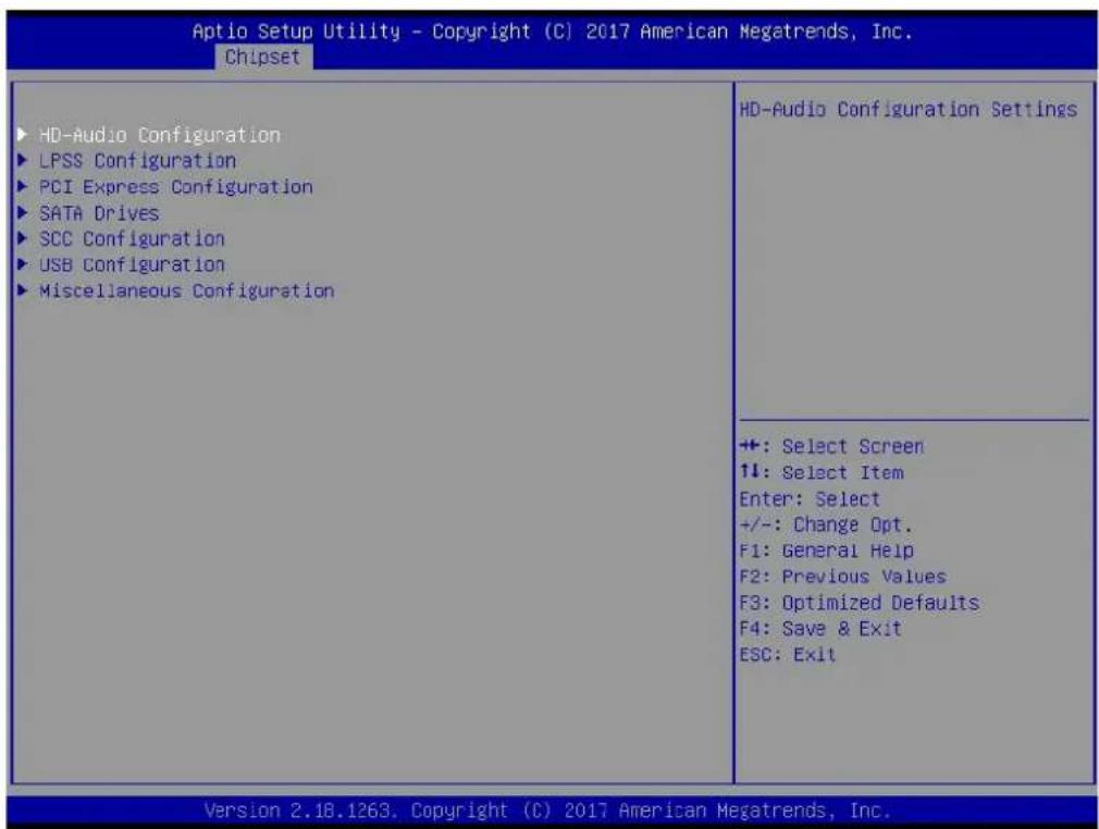
text_image
Aptio Setup Utility - Copyright (C) 2017 American Megatrends, Inc. Chipset ► HD-Audio Configuration ► LPSS Configuration ► PCI Express Configuration ► SATA Drives ► SCC Configuration ► USB Configuration ► Miscellaneous Configuration HD-Audio Configuration Settings +: Select Screen ↑↓: Select Item Enter: Select +/-: Change Opt. F1: General Help F2: Previous Values F3: Optimized Defaults F4: Save & Exit ESC: Exit Version 2.18.1263. Copyright (C) 2017 American Megatrends, Inc.■ HD-Audio Configuration
HD-Audio Configuration Settings.
LPSS Configuration
LPSS Configuration Settings.
■ PCI Express Configuration
PCI Express Configuration Settings.
SATA Drives
Press
■ SCC Configuration
SCC Configuration Settings.
USB Configuration
USB Configuration Settings.
■ Miscellaneous Configuration
Enable/Disable Misc. Features.
3.1.3.4.1 HD-Audio Configuration

text_image
Aptio Setup Utility - Copyright (C) 2017 American Megatrends, Inc. Chipset HD-Audio Configuration HD-Audio Support [Enabled] Enable/Disable HD-Audio Support +: Select Screen ↑↓: Select Item Enter: Select +/-: Change Opt. F1: General Help F2: Previous Values F3: Optimized Defaults F4: Save & Exit ESC: Exit Version 2.18.1263. Copyright (C) 2017 American Megatrends, Inc.HD-Audio Support
Enable/Disable HD-Audio Support.
text_image
Aptio Setup Utility - Copyright (C) 2017 American Megatrends, Inc. Chipset Low Power Sub System LPSS I2C #1 Support (D22:F0) [PCI Mode] Set LPSS I2C #1 Speed [Fast Mode] Enable/Disable LPSS I2C #1 Support +: Select Screen ↑↓: Select Item Enter: Select +/-: Change Opt. F1: General Help F2: Previous Values F3: Optimized Defaults F4: Save & Exit ESC: Exit Version 2.18.1263. Copyright (C) 2017 American Megatrends, Inc.■ LPSS I2C #1 Support (D22:F0)
Enable/Disable LPSS I2C #1 Support.
■ Set LPSS I2C #1 Speed
Select LPSS I2C #1 Speed.
3.1.3.4.3PCI Express Configuration

text_image
Aptio Setup Utility - Copyright (C) 2017 American Megatrends, Inc. Chipset PCI Express Configuration Compliance Mode [Disabled] ► PCI Express Root Port 1 ► PCI Express Root Port 5 Onboard LAN1 Controller [Enabled] LAN1 Wake from S5 [Disabled] Onboard LAN2 Controller [Enabled] LAN2 Wake from S5 [Disabled] Onboard LAN3 Controller [Enabled] LAN3/PCIE Wake from S5 [Disabled] Onboard X102001 Controller [Enabled] PCI PME Wake from S5 [Disabled] Compliance Mode Enable/Disable +: Select Screen ↑↓: Select Item Enter: Select +/-: Change Opt. F1: General Help F2: Previous Values F3: Optimized Defaults F4: Save & Exit ESC: Exit Version 2.18.1263. Copyright (C) 2017 American Megatrends, Inc.Compliance Mode
Compliance Mode Enable/Disable.
PCI Express Root Port 1 / 5
Control the PCI Express Root Port.
Onboard LAN1/LAN2/LAN3 Controller
Select to Enable or Disable Onboard LAN1/LAN2/LAN3 Controller.
■ LAN Option ROM
Enabled / Disabled Onboard LAN's PXE option ROM.
Onboard XIO2001 Controller
Select to Enable or Disable Onboard PCI-to-PCI Bridge.
PCI PME Wake from S5
Enable or disable PCI PME to wake the system from S5.
text_image
Aptio Setup Utility - Copyright (C) 2017 American Megatrends, Inc. Chipset SATA Drives Chipset-SATA Controller Configuration Chipset SATA [Enabled] SATA Port 0 [Not Installed] Port 0 [Enabled] SATA Device Type [Hard Disk Drive] SATA Port 1/mSATA [Not Installed] Port 1 [Enabled] SATA Device Type [Hard Disk Drive] Enables or Disables the Chipset SATA Controller. The Chipset SATA controller supports the 2 black internal SATA ports (up to 3Gb/s supported per port). ++: Select Screen ↑↓: Select Item Enter: Select +/-: Change Opt. F1: General Help F2: Previous Values F3: Optimized Defaults F4: Save & Exit ESC: Exit Version 2.18.1263. Copyright (C) 2017 American Megatrends, Inc.Chipset SATA
Enable or Disable the Chipset SATA Controller.
3.1.3.4.5 SCC Configuration
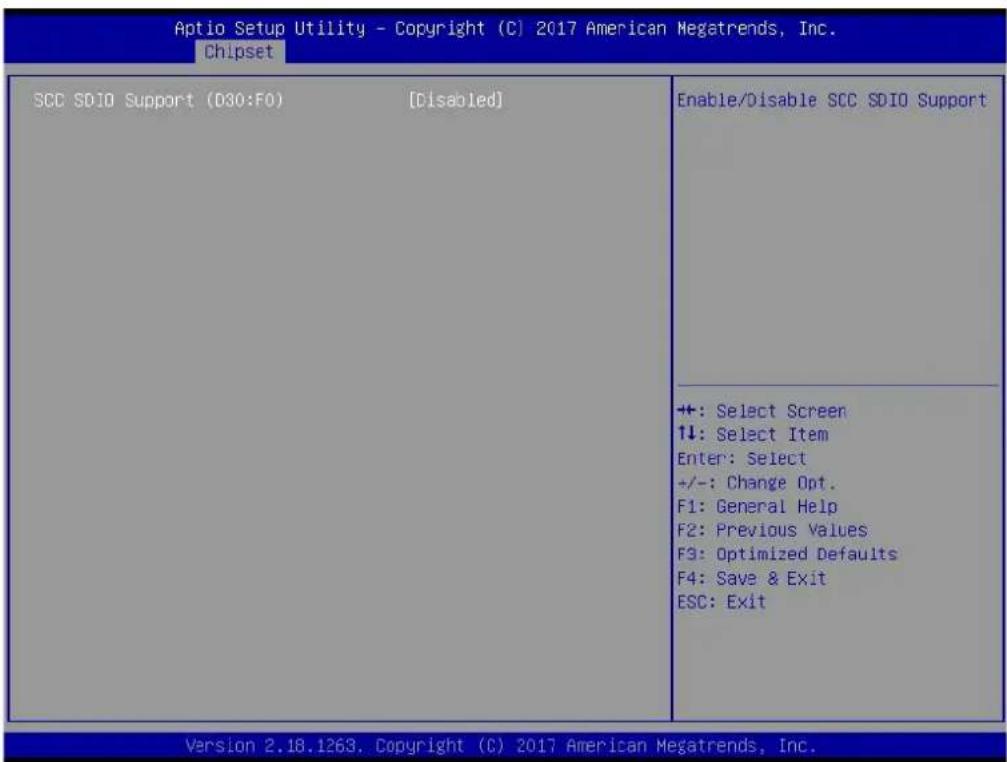
text_image
Aptio Setup Utility - Copyright (C) 2017 American Megatrends, Inc. Chipset SCC SDIO Support (D30:F0) [Disabled] Enable/Disable SCC SDIO Support +: Select Screen ↑↓: Select Item Enter: Select +/-: Change Opt. F1: General Help F2: Previous Values F3: Optimized Defaults F4: Save & Exit ESC: Exit Version 2.18.1263. Copyright (C) 2017 American Megatrends, Inc.■ SCC SDIO Support (D30:F0)
Enable/Disable SCC SDIO Support.
3.1.3.4.6USB Configuration

text_image
Aptio Setup Utility - Copyright (C) 2017 American Megatrends, Inc. Chipset XHCI Pre-Boot Driver [Disabled] XHCI Mode [Enabled] USB Port Disable Override [Disabled] XHCI Disable Compliance Mode [FALSE] USB HW MODE AFE Comparators [Disabled] Enable/Disable XHCI Pre-Boot Driver support. +: Select Screen +: Select Item Enter: Select +/-: Change Opt. F1: General Help F2: Previous Values F3: Optimized Defaults F4: Save & Exit ESC: Exit Version 2.18.1263. Copyright (C) 2017 American Megatrends, Inc.XHCI Pre-Boot Driver
Enable/Disable XHCI Pre-Boot Driver Support.
USB Port Disable Override
Selectively Enable/Disable corresponding USB port from reporting a Device Connection to the controller.
■ XHCI Disable Compliance Mode
Options to disable XHCI Link Compliance Mode.
USB HW MODE AFE Comparators
Enable/Disable USB HW MODE AFE Comparators.
3.1.3.4.7 Miscellaneous Configuration
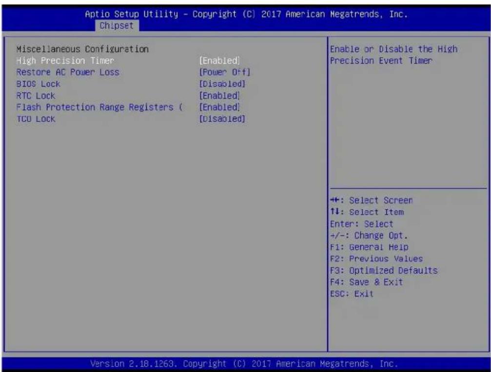
text_image
Aptio Setup Utility - Copyright (C) 2017 American Megatrends, Inc. Chipset Miscellaneous Configuration High Precision Timer [Enabled] Restore AC Power Loss [Power Off] BIOS Lock [Disabled] RTC Lock [Enabled] Flash Protection Range Registers ( [Enabled] TCO Lock [Disabled] Enable or Disable the High Precision Event Timer +: Select Screen ↑↓: Select Item Enter: Select +/-: Change Opt. F1: General Help F2: Previous Values F3: Optimized Defaults F4: Save & Exit ESC: Exit Version 2.18.1263. Copyright (C) 2017 American Megatrends, Inc.■ High Precision Timer
Enable or Disable the High Precision Timer.
Specify what state to go to when power is re-applied after a power failure (G3 state).
BIOS Lock
Enable/Disable the BIOS Lock Enable feature.
RTC Lock
Enable or disable bytes 38h-3Fh in the upper and lower 128-byte bank of RTC RAM lockdown.
■ Flash Protection Range Registers
Enable/Disable the SC BIOS Lock Enable feature.
TCO SMI Lock
Enable TCO and Lock Down TCO.
3.1.4 Security

text_image
Aptio Setup Utility - Copyright (C) 2017 American Megatrends, Inc. Main Advanced Chipset Security Boot Save & Exit Password Description If ONLY the Administrator's password is set, then this only limits access to Setup and is only asked for when entering Setup. If ONLY the User's password is set, then this is a power on password and must be entered to boot or enter Setup. In Setup the User will have Administrator rights. The password length must be in the following range: Minimum length 3 Maximum length 20 Setup Administrator Password User Password Set Setup Administrator Password +: Select Screen 1↓: Select Item Enter: Select +/-: Change Opt. F1: General Help F2: Previous Values F3: Optimized Defaults F4: Save & Exit ESC: Exit Version 2.18.1263, Copyright (C) 2017 American Megatrends, Inc.Select Security Setup from the PCM-9563 Setup main BIOS setup menu. All Security Setup options, such as password protection and virus protection are described in this section. To access the sub menu for the following items, select the item and press
■ Change Administrator / User Password
Select this option and press
3.1.5 Boot
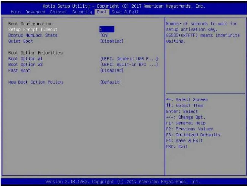
text_image
Aptio Setup Utility - Copyright (C) 2017 American Megatrends, Inc. Main Advanced Chipset Security Boot Save & Exit Boot Configuration Setup Prompt Timeout Bootup NumLock State Quiet Boot 1 [On] [Disabled] Boot Option Priorities Boot Option #1 Boot Option #2 Fast Boot [UEFI: Generic USB F...] [UEFI: Built-in EFI ...] [Disabled] New Boot Option Policy [Default] Number of seconds to wait for setup activation key. 65535(0xFFFF) means indefinite waiting. +: Select Screen ↑↓: Select Item Enter: Select +/-: Change Opt. F1: General Help F2: Previous Values F3: Optimized Defaults F4: Save & Exit ESC: Exit Version 2.18.1263, Copyright (C) 2017 American Megatrends, Inc.Setup Prompt Timeout
Number of seconds that the firmware will wait before initiating the original default boot selection. A value of 0 indicates that the default boot selection is to be initiated immediately on boot. A value of 65535(0xFFFF) indicates that firmware will wait for user input before booting. This means the default boot selection is not automatically started by the firmware.
■ Bootup NumLock State
Select the keyboard NumLock state.
Quiet Boot
Enables or disables Quiet Boot option.
■ Boot Option #1
Sets the system boot order.
Fast Boot
Enables or disables boot with initialization of a minimal set of devices required to launch active boot option. Has no effect for BBS boot options.
■ New Boot Option Policy
Controls the placement of newly detected UEFI boot options.
3.1.6 Save & Exit
| Aptio Setup Utility - Copyright (C) 2017 American Megatrends, Inc. | |
| Main Advanced Chipset Security Boot Save & Exit | |
| Save OptionsSave Changes and ExitDiscard Changes and ExitSave Changes and ResetDiscard Changes and ResetSave ChangesDiscard ChangesDefault OptionsRestore DefaultsSave as User DefaultsRestore User DefaultsBoot OverrideUEFI: Generic USB Flash Disk PMAP, Partition 1UEFI: Built-in EFI ShellLaunch EFI Shell from filesystem device | Exit system setup after saving the changes.+: Select Screen1↓: Select ItemEnter: Select+/-: Change Opt.F1: General HelpF2: Previous ValuesF3: Optimized DefaultsF4: Save & ExitESC: Exit |
■ Save Changes and Exit
This item allows you to exit system setup after saving the changes.
■ Discard Changes and Exit
This item allows you to exit system setup without saving any changes.
■ Save Changes and Reset
This item allows you to reset the system after saving the changes.
■ Discard Changes and Reset
This item allows you to rest system setup without saving any changes.
■ Save Changes
This item allows you to save changes done so far to any of the options.
■ Discard Changes
This item allows you to discard changes done so far to any of the options.
Restore Defaults
This item allows you to restore/load default values for all the options.
■ Save as User Defaults
This item allows you to save the changes done so far as user defaults.
Restore User Defaults
This item allows you to restore the user defaults to all the options.
Boot Override
Boot device select can override your boot priority.
Chapter 4
Extension I/O Installation

text_image
1935030600*4pcs Align the pin connector carefully and apply force evenly. 193A231540*4pcs 1910000041*4pcs
text_image
PCI Card Backplane Align carefully; apply force evenly Make sure the PCI card is fully seated.Appendix A
Pin Assignments
CN1 12V Power Input
Part Number 1655004509-01
Footprint WF_2x2P_165_BOX_D
Description
Pin Pin Name
| 1 | GND |
| 2 | GND |
| 3 +12V | |
| 4 +12V |
CN3 Standby Power Input
Part Number 1655303020
Footprint WHL3V-2M
Description WAFER BOX 3P 2.0mm 180D(M) DIP 2001-WS-3
Pin Pin Name
1 +5VSB
2 GND
3 PSON#

CN4 5V power output
Part Number 1655002000
Footprint WF_2P_100_D
Description WAFER 2P 2.54mm 180D(M) DIP 2542-WS-2
Pin Pin Name
| 1 | +5V |
| 2 | GND |

CN5 Battery
Part Number 1655902032
Footprint WHL2V-125
Description WAFER BOX 2P 1.25mm 180D(M) DIP 53047-0210
Pin Pin Name
| 1 | +3V |
| 2 | GND |

CN6 SODIMMDDR3RVS_204
Part Number 1651002082-11
Footprint DDR3_204P_AS0A626-N2
Description
Pin Pin Name
CN8 Power Switch
Part Number 1655302020
Footprint WF_2P_79_BOX_R1_D
Description WAFER BOX 2P 2.0mm 180D(M) DIP A2001WV2-2P
Pin Pin Name
1 PSIN
2 GND

CN9 Reset
Part Number 1655302020
Footprint WF_2P_79_BOX_R1_D
Description WAFER BOX 2P 2.0mm 180D(M) DIP A2001WV2-2P
Pin Pin Name
1 RESET#
2 GND

CN10 Audio
Part Number 1653208260
Footprint HD_8x2P_79_BOX
Description BOX HEADER 8x2P 2.00mm 180D(M) SMD 23N6850
Pin Pin Name
| 1 SPK_R+ |
| 2 SPK_R- |
| 3 SPK_L+ |
| 4 SPK_L- |
| 5 | L | O | U |
| 6 | L | O | U |
| 7 | GND |
| 8 | GND |
| 9 | L | I | N |
| 10 LINL |
| 11 GND |
| 12 GND |
| 13 NC |
| 14 MICR |
| 15 MICL |
| 16 GND |
| 8 RX-(10/100),BI_DB-(GHz) |
| 9 TX+(10/100),BI_DA+(GHz) |
| 10 TX-(10/100),BI_DA-(GHz) |
text_image
2 3 4 5 6 7 8 9 1 2 3 4 5 6 7 8 9CN12 LAN1/2 LED
Part Number 1653004260
Footprint HD_4x2_79
Description PIN HEADER 4x2P 2.0mm 180D(M) SMD 21N22050
Pin Pin Name
1 +V3.3 LAN1CON
2 GND
3 LAN1_LINK100#
4 LAN2_LINK100#
5 LAN1_ACT#
6 LAN2_ACT#
7 LAN1_LINK1000#
8 LAN2_LINK1000#

CN13 LAN2
Part Number 1653205260
Footprint HD_5x2P_79_BOX
Description BOX HEADER 5x2P 2.0mm 180D(M) SMD 23N6850
Pin Pin Name
1 GND 2 GND
3 BI_DD+(GHz)
4 BI_DD-(GHz)
5 BI_DC+(GHz)
6 BI_DC-(GHz)
7 RX+(10/100), BI_DB+(GHz)
8 RX-(10/100), BI_DB-(GHz)
9 TX+(10/100), BI_DA+(GHz)
10 TX-(10/100), BI_DA-(GHz)
text_image
2 1 2 3 4 5 6 7 8 9 1 2 3 4 5 6 7 8 9CN14 LAN3
Part Number 1653205260
Footprint HD_5x2P_79_BOX
Description BOX HEADER 5x2P 2.0mm 180D(M) SMD 23N6850
Pin Pin Name
natural_image
Pure electrical connector diagram without any text or symbolsCN19 SATA
Part Number 1654004659
Footprint SATA_7P_WATM-07DBN4A3B8UW_D
Description Serial ATA 7P 1.27mm 180D(M) DIP WATM-07DBN4A3B8
Pin Pin Name
| 1 | GND |
| 2 | TX+ |
| 3 | TX- |
| 4 | GND |
| 5 | RX- |
| 6 | RX+ |
| 7 | GND |

natural_image
Pure electrical connector pinout diagram without any text or symbolsCN20 mSATA
Part Number 1654002538
Footprint FOX_AS0B226-S68K7F
Description MINI PCI E 52P 6.8mm 90D SMD AS0B226-S68Q-7H
Pin Pin Name
1 WAKE#
2 +3.3VSB
3 NC
4 GND
5 NC
6 +1.5V
7 NC
8 U I M
9 GND
10 UIM_DATA
11 REFCLK-
12 UIM_CLK
13 REFCLK+
14 UIM_RESET
15 GND
16 UIM_VPP
17 NC
18 GND
19 NC
20 W_DISABLE#
21 GND
22 PERST#
23 PERn0
24 +3.3VSB
25 PERp0
26 GND
27 GND
28 +1.5V
29 GND
30 SMB_CLK
31 PETn0
32 SMB_DAT
33 PETp0
34 GND
35 GND
36 USB D-
37 GND
38 USB D+
39 +3.3VSB
40 GND
41 +3.3VSB
42 NC
43 GND
44 NC
45 NC
46 NC
47 NC
48 +1.5V
49 NC
50 GND
51 NC
52 +3.3VSB

text_image
53 52 50 48 46 44 42 40 38 36 34 32 30 28 26 24 22 20 18 16 14 12 10 8 6 4 2 54 55 51 49 47 45 43 41 39 37 35 33 31 29 27 25 23 21 19 17 15 13 11 9 7 5 3 1 56CN21 M.2 connector symbol
Part Number 1654011871-01
Footprint NGFF_75P_2199230-2
Description
Pin Pin Name
| 1 | GND |
| 2 +3.3VSB | |
| 3 USB_D+ | |
| 4 +3.3VSB | |
| 5 USB_D- | |
| 7 | GND |
9 SDIO_CLK
11 SDIO_CMD
13 SDIO_DATA0
15 SDIO_DATA1
17 SDIO_DATA2
18 GND
19 SDIO_DATA3
21 SDIO_WAKE#
23 SDIO_RESET#
33 GND
35 PETp0
37 PETn0
39 GND
41 PERp0
43 PERn0
45 GND
47 REFCLK+
49 REFCLK-
51 GND
52 PERESET#
54 W_DISABLE#2
55 PEWAKE#
56 W_DISABLE#1
57 GND
59 NC
61 NC
63 GND
64 NC
65 NC
67 NC
69 GND
71 NC
73 NC
75 GND
| CN22 COM1/COM2 | |||
| Part Number 1653004793 | |||
| Footprint HD_10x2P_79_23N685B-20M10 | |||
| Description | BOX HEADER 10x2P 2.0mm 180D(M)SMD 23N685B-20M10B | ||
| Pin Pin Name | |||
| 1 DCD1# | |||
| 2 | D | S | R |
| 3 | R | X | D |
| 4 | R | T | S |
| 5 | T | X | D |
| 6 | C | T | S |
| 7 | D | T | R |
| 8 | R | I | 1 |
| 9 | GND | ||
| 10 GND | |||
| 11 DCD2# | |||
| 12 DSR2# | |||
| 13 RXD2 | |||
| 14 RTS2# | |||
| 15 TXD2 | |||
| 16 CTS2# | |||
| 17 DTR2# | |||
| 18 RI2# | |||
| 19 GND | |||
| 20 GND | |||

text_image
1 3 5 7 9 11 13 15 17 19 20 4 6 8 10 12 14 16 18 20CN23 COM3/COM4
Part Number 1653004793
Footprint HD_10x2P_79_23N685B-20M10
| Description | BOX HEADER 10x2P 2.0mm 180D(M)SMD 23N685B-20M10B | ||
| Pin Pin Name | |||
| 1 | D | C | D |
| 2 | D | S | R |
| 3 | R | X | D |
| 4 | R | T | S |
| 5 | T | X | D |
| 6 | C | T | S |
| 7 | D | T | R |
| 8 | R | I | 3 |
| 9 | GND | ||
| 10 GND | |||
| 11 DCD4# | |||
| 12 DSR4# | |||
| 13 RXD4 | |||
| 14 RTS4# | |||
| 15 TXD4 | |||
| 16 CTS4# | |||
| 17 DTR4# | |||
| 18 RI4# | |||
| 19 GND | |||
| 20 GND | |||

text_image
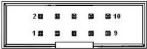
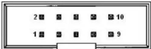
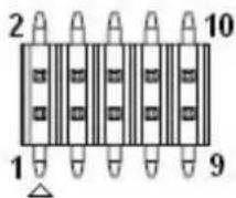
1 3 5 7 9 11 13 15 17 19 2 4 6 8 10 12 14 16 18 20CN24 COM5/COM6
Part Number 1653205260
Footprint HD_5x2P_79_BOX
Description BOX HEADER 5x2P 2.0mm 180D(M) SMD 23N6850
Pin Pin Name
1 COM5_422_RXD-
2 COM6_422_RXD-
3 COM5_422_RXD+
4 COM6_422_RXD+
5 COM5_485-422_TXD+
6 COM6_485-422_TXD+
7 COM5_485-422_TXD-
8 COM6_485-422_TXD-
9 GND
10 GND
text_image
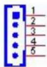
2 3 4 5 6 7 8 9 1 2 3 4 5 6 7 8 9CN25 Inverter Power Output
Part Number 1655000453
Footprint WHL5V-2M-24W1140
Description WAFER BOX 2.0mm 5P 180D(M) DIP WO/Pb JIH VEI
Pin Pin Name
1 + 1 2
2 GND
3 ENABKL
4 VBR
5 +5V
CN26 48 bits LVDS Panel
Part Number 1653920200
Footprint SPH20X2
Description B/B Conn. 40P 1.25mm 90D SMD DF13-40DP-1.25V(91)
Pin Pin Name
| 1 | +5V | ||
| 2 | G | P | I |
| 3 | G | P | I |
| 4 | G | P | I |
| 5 | G | P | I |
| 6 | G | P | I |
| 7 | G | P | I |
| 8 | G | P | I |
| 9 | G | P | I |
| 10 GND | |||
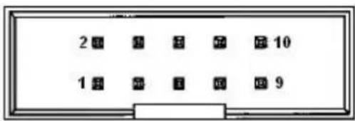
CN39 GPIO8-15
Part Number 1653005261
Footprint HD_5x2P_79
Description PIN HEADER 5x2P 2.0mm 180D(M) SMD 21N22050
Pin Pin Name
| 1 | +5V | |||
| 2 | G | P | I | O |
| 3 | G | P | I | O |
| 4 | G | P | I | O |
| 5 | G | P | I | O |
| 6 | G | P | I | O |
| 7 | G | P | I | O |
| 8 | G | P | I | O |
| 9 | G | P | I | O |
| 10 GND | ||||

CN40 Smart FAN
Part Number 1655004347
Footprint WF_4P_100_D_744-81-04TW30
Description
Pin Pin Name
| 1 | GND | ||
| 2 | + | 1 | 2 |
| 3 SPEED | |||
| 4 | PWM | ||

CN45 PCI Slot
Part Number 1654002099
Footprint SL-PCI
Description SLOT 60x2P 180D(F) DIP EH06001-HHW-DF
Pin Pin Name
| A1 NC |
| A2 +12V |
| A3 NC |
| A4 NC |
| A5 +5V |
| A6 INTA# |
| A7 INTC# |
| A8 +5V |
| A9 GNT# |
| A10 VI/O (+5V or +3.3V) |
| A11 GNT# |
| A12 GND |
| A13 GND |
| A14 +3.3VSB |
| A15 RESET# |
| A16 VI/O (+5V or +3.3V) |
| A17 GNT# |
| A18 GND |
| A19 PME# |
| A20 AD30 |
| A21 +3.3V |
| A22 AD28 |
| A23 AD26 |
| A24 GND |
| A25 AD24 |
| A26 IDSEL |
| A27 +3.3V |
A28 AD22
A29 AD20
A30 GND
A31 AD18
A32 AD16
A33 +3.3V
A34 FRAME#
A35 GND
A36 TRDY#
A37 GND
A38 STOP#
A39 +3.3V
A40 NC
A41 NC
A42 GND
A43 PAR
A44 AD15
A45 +3.3V
A46 AD13
A47 AD11
A48 GND
A49 AD09
A52 C/BE0#
A53 +3.3V
A54 AD06
A55 AD04
A56 GND
A57 AD02
A58 AD00
A59 VI/O (+5V or +3.3V)
A60 NC
A61 +5V
A62 +5V
B1 -12V
B2 NC
B3 GND
B4 NC
B5 +5V
B6 +5V
B7 INTB#
B8 INTD#
B9 NC
B10 REQ#
B11 NC
B12 GND
B13 GND
B14 CLK
B15 GND
| B16 CLK |
| B17 GND |
| B18 REQ# |
| 19 VI/O (+5V or +3.3V) |
| B20 AD31 |
| B21 AD29 |
| B22 GND |
| B23 AD27 |
| B24 AD25 |
| B25 +3.3V |
| B26 C/BE3# |
| B27 AD23 |
| B28 GND |
| B29 AD21 |
| B30 AD19 |
| B31 +3.3V |
| B32 AD17 |
| B33 C/BE2# |
| B34 GND |
| B35 IRDY# |
| B36 +3.3V |
| B37 DEVSEL# |
| B38 GND |
| B39 LOCK# |
| B40 PERR# |
| B41 +3.3V |
| B42 SERR# |
| B43 +3.3V |
| B44 C/BE1# |
| B45 AD14 |
| B46 GND |
| B47 AD12 |
| B48 AD10 |
| B49 GND |
| B52 AD08 |
| B53 AD07 |
| B54 +3.3V |
| B55 AD05 |
| B56 AD03 |
| B57 GND |
| B58 AD01 |
| B59 VI/O (+5V or +3.3V) |
| B60 NC |
| B61 +5V |
| B62 +5V |
CN46 PWR/HDD/LAN3 LED
Part Number 1653004260
Footprint HD_4x2_79
Description PIN HEADER 4x2P 2.0mm 180D(M) SMD 21N22050
Pin Pin Name
| 1 | P | W | R |
| 2 | H | D | D |
| 3 | P | W | R |
| 4 | H | D | D |
5 +V3.3_LAN
6 LAN3_LINK100#
7 LAN3_ACT#
8 LAN3_LINK1000#

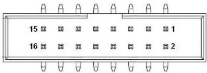
CN48 PCI-104 -12V Input
Part Number 1653002101
Footprint HD_2x1P_79_D
Description PIN HEADER 2*1P 180D(M)SQUARE 2.0mm DIP W/O Pb
Pin Pin Name
| 1 -12V | |
| 2 | GND |

Appendix B
Optional Extras for PCM-9563 A1
The PCM-9563 requires several cables for normal operation. You can make them yourself or purchase an optional cable kit assembly, which includes the following
B.1 PCM-10586-9563E Cable kit for PCM-9563
Table B.1: PCM-10586-9562E Cable kit for PCM-9562 A1
| P/N | Cable Description | Quantity | PCM-9563 Connector | Terminating Connector |
| 1700001296 VGA cable 1 CN27 | A Cable D-SUB 15P(F)/2*8P-2.0 15CM | |||
| 1700002142 GbE cable 3 | CN11,CN13, CN14 | A Cable IDE#3 10P-2.0/RJ45-8P8C 15CM | ||
| 1700008941 SATA cable 2 CN18,CN19 | M Cable SATA 7P/SATA 7P 32CM C=R 180/180D W/Lock | |||
| 1700019109 COM5.6 cable 1 CN24 | F Cable 2*5P-2.0/D-SUB 9P(M)*2 25cm | |||
| 1700160160 Audio cable 1 CN10 | A Cable 2*8P-2.0/JACK*5 16cm C=B | |||
| 1700260250 LTP cable 1 CN34 | F Cable IDE#2 26P-2.0/D-SUB 25P(F) 25CM | |||
| 1703060191 | PS2/ KB, MS cable | 1 CN35 | A Cable 1*6P-2.0/M-DIN 6P(F)*2 22cm | |
| 1703100260 USB2.0 cable 3 | CN30.CN31, CN32 | A cable USB-A 4P*2/2*5-2.0 26cm W/BKT | ||
| 1701200220 COM X2 cable 2 CN22,CN23 | F Cable IDE#2 10P-2.0/D-SUB 9P(M) 25CM | |||
| 1700020277-01 | USB 3.0 cable 1 CN33 | M Cable 2*10P-2.0/USB-A 9P(F)*2 30CM W/BKT | ||
Note!
The cables PN maybe change because vendor phase out or change cable in the future. So, for detail information please refer to PCM-10586-9562E user note.

Appendix C
System Assignments
C.1 1st MB Memory Map
Table C.1: 1st MB memory map
| Addr. Range (Hex) Device |
| E0000h - FFFFFh System ROM |
| D0000h - DFFFFh System RAM |
| C0000h - CFFFFh VGA BIOS |
| A0000h - BFFFFh Legacy Video Area |
| 00000h - 9FFFFh Base memory |
C.2 DMA Channel Assignments
Table C.2: DMA channel assignments
| Channel Function | |
| 0 | Available |
| 1 | Available |
| 2 | Available |
| 3 | Available (parallel port)** |
| 4 | Cascade for DMA controller 1 |
| 5 | Available |
| 6 | Available |
| 7 | Available |
| ** | Parallel port DMA default setting: DMA 3, Parallel port DMA selection: DMA 1 or 3 |
C.3 Interrupt Assignments
Table C.3: Interrupt assignments
| Interrupt# Interrupt source | |||
| IRQ0 | System | timer | |
| IRQ1 Using SERIRQ, Keyboard Emulation | |||
| IRQ2 | Interrupt | from | controller 2 (cascade) |
| IRQ3 | Communications Port (COM2) | ||
| IRQ4 | Communications | Port | (COM1) |
| IRQ5 LPT Port (LPT1) | |||
| IRQ6 | Available | ||
| IRQ7 | Communications | Port | (COM3) |
| IRQ8 System CMOS/real time clock | |||
| IRQ9 | Microsoft ACPI-Compliant System | ||
| IRQ10 | Communications Port (COM5) | ||
| IRQ11 | Communications Port (COM4) | ||
| IRQ12 | Available | ||
| IRQ13 | Numeric data processor | ||
| IRQ14 | Reserved | ||
| IRQ15 | Communications Port (COM6) | ||
| * Refer to the table of msd.exe | |||
Table C.4: System I/O Ports
| Addr. Range (Hex) Device | |
| 00-1F | Reserved |
| 20-2D | Interrupt Controller |
| 2E-2F | Motherboard resources |
| 30-3D | Interrupt Controller |
| 40-43 | Timer Register |
| 4E-4F | Motherboard resources |
| 50-53 | Timer/Counter |
| 60-67 | NMI Register/Keyboard Controller |
| 70-7F | Real-time clock, non-maskable interrupt (NMI) mask, PMC Regis-ter |
| 80-9F | DMA page register |
| A0-BF | Motherboard resources |
| C0-DF | Reserved |
| F0-F1 | Reserved |
| 278-278 | LPT Port Alternate Port (LPT1) |
| 299-29A | EC HM Index port and Data port |
| 29C-29D | EC Index port and Data port |
| 2E0-2E7 | Communications Port (COM5) |
| 2E8-2EF | Communications Port (COM4) |
| 2F8-2FF | Communications Port (COM2) |
| 378-378 | LPT Port (LPT1) |
| 3BC-3BC | LPT Port Alternate Port (LPT1) |
| 3C0-3DF | Motherboard resources |
| 3E0-3E7 | Communications Port (COM6) |
| 3E8-3EF | Communications Port (COM3) |
| 3F8-3FF | Communications Port (COM1) |
| 4D0-4D1 | Motherboard resources |
ADVANTECH
Enabling an Intelligent Planet
www.advantech.com
Please verify specifications before quoting. This guide is intended for reference purposes only.
All product specifications are subject to change without notice.
No part of this publication may be reproduced in any form or by any means, electronic, photocopying, recording or otherwise, without prior written permission of the publisher.
All brand and product names are trademarks or registered trademarks of their respective companies.
© Advantech Co., Ltd. 2017