SOM-2533DNCC-S8A1 - Computers Advantech - Free user manual and instructions
Find the device manual for free SOM-2533DNCC-S8A1 Advantech in PDF.

User questions about SOM-2533DNCC-S8A1 Advantech
0 question about this device. Answer the ones you know or ask your own.
Ask a new question about this device
Download the instructions for your Computers in PDF format for free! Find your manual SOM-2533DNCC-S8A1 - Advantech and take your electronic device back in hand. On this page are published all the documents necessary for the use of your device. SOM-2533DNCC-S8A1 by Advantech.
USER MANUAL SOM-2533DNCC-S8A1 Advantech
natural_image
Illustration of four electronic circuit boards with white outlines on a purple background (no text or symbols)SOM-2533
CPU Computer on Module
Copyright
The documentation and the software included with this product are copyrighted 2024 by Advantech Co., Ltd. All rights are reserved. Advantech Co., Ltd. reserves the right to make improvements in the products described in this manual at any time without notice. No part of this manual may be reproduced, copied, translated, or transmitted in any form or by any means without the prior written permission of Advantech Co., Ltd. The information provided in this manual is intended to be accurate and reliable. However, Advantech Co., Ltd. assumes no responsibility for its use, nor for any infringements of the rights of third parties that may result from its use.
Acknowledgments
AMD is a trademark of AMD Corporation.
Microsoft Windows and MS-DOS are registered trademarks of Microsoft Corp.
All other product names or trademarks are properties of their respective owners.
Product Warranty (2 Years)
Advantech warrants the original purchaser that each of its products will be free from defects in materials and workmanship for two years from the date of purchase.
This warranty does not apply to any products that have been repaired or altered by persons other than repair personnel authorized by Advantech, or products that have been subject to misuse, abuse, accident, or improper installation. Advantech assumes no liability under the terms of this warranty as a consequence of such events.
Because of Advantech's high quality-control standards and rigorous testing, most customers never need to use our repair service. If an Advantech product is defective, it will be repaired or replaced free of charge during the warranty period. For out-of-warranty repairs, customers will be billed according to the cost of replacement materials, service time, and freight. Please consult your dealer for more details.
If you believe your product to be defective, follow the steps outlined below.
-
Collect all the information about the problem encountered. (For example, CPU speed, Advantech products used, other hardware and software used, etc.) Note anything abnormal and list any onscreen messages displayed when the problem occurs.
-
Call your dealer and describe the problem. Please have your manual, product, and any helpful information readily available.
-
If your product is diagnosed as defective, obtain a return merchandise authorization (RMA) number from your dealer. This allows us to process your return more quickly.
-
Carefully pack the defective product, a completed Repair and Replacement Order Card, and a proof of purchase date (such as a photocopy of your sales receipt) into a shippable container. Products returned without a proof of purchase date are not eligible for warranty service.
-
Write the RMA number clearly on the outside of the package and ship the package prepaid to your dealer.
Part No. 2006253300 Edition 1
Printed in Taiwan March 2024
Declaration of Conformity
CE
This product has passed the CE test for environmental specifications when shielded cables are used for external wiring. We recommend the use of shielded cables. This type of cable is available from Advantech. Please contact your local supplier for ordering information.
Test conditions for passing also include the equipment being operated within an industrial enclosure. In order to protect the product from damage caused by electrostatic discharge (ESD) and EMI leakage, we strongly recommend the use of CE-compliant industrial enclosure products.
FCC Class B
This equipment has been tested and found to comply with the limits for a Class B digital device, pursuant to part 15 of the FCC Rules. These limits are designed to provide reasonable protection against harmful interference in a residential installation. This equipment generates, uses, and can radiate radio frequency energy and, if not installed and used in accordance with the instruction manual, may cause harmful interference to radio communications. However, there is no guarantee that interference will not occur in a particular installation. If this equipment does cause harmful interference to radio or television reception, which can be determined by turning the equipment off and on, the user is encouraged to try to correct the interference by one or more of the following measures:
■ Reorient or relocate the receiving antenna.
■ Increase the separation between the equipment and receiver.
■ Connect the equipment into an outlet on a circuit different from that to which the receiver is connected.
Consult the dealer or an experienced radio/TV technician for assistance.
FM
This equipment has passed FM certification. According to the National Fire Protection Association, work sites are categorized into different classes, divisions, and groups based on hazard considerations. This equipment is compliant with the specifications for Class I, Division 2, Groups A, B, C, and D indoor hazards.
Technical Support and Assistance
- Visit the Advantech website at www.advantech.com/support to obtain the latest product information.
- Contact your distributor, sales representative, or Advantech's customer service center for technical support if you need additional assistance. Please have the following information ready before calling:
– Product name and serial number
– Description of your peripheral attachments
– Description of your software (operating system, version, application software, etc.)
– A complete description of the problem - The exact wording of any error messages
Warnings, Cautions, and Notes
Warning! Warnings indicate conditions that could cause personal injury if not observed!

Caution! Cautions are included to help prevent hardware damage and data loss. For example,

"Batteries are at risk of exploding if incorrectly installed. Do not attempt to recharge, force open, or heat the battery. Replace the battery only with the same or equivalent type as recommended by the manufacturer. Discard used batteries according to the manufacturer's instructions."
Note! Notes provide additional and/or optional information.

Document Feedback
To assist us with improving this manual, we welcome all comments and constructive criticism. Please send all feedback in writing to support@advantech.com.
Safety Precautions - Static Electricity
Follow these simple precautions to protect yourself from harm and the products from damage.
To avoid electrical shock, always disconnect the power from the PC chassis before manual handling. Do not touch any components on the CPU card or other cards while the PC is powered on.
- Disconnect the power before making any configuration changes. A sudden rush of power after connecting a jumper or installing a card may damage sensitive electronic components.
Safety Instructions
- Read these safety instructions carefully.
- Retain this user manual for future reference.
- Disconnect the equipment from all power outlets before cleaning. Use only a damp cloth for cleaning. Do not use liquid or spray detergents.
-
For pluggable equipment, the power outlet socket must be located near the equipment and easily accessible.
-
Protect the equipment from humidity.
-
Place the equipment on a reliable surface during installation. Dropping or letting the equipment fall may cause damage.
-
The openings on the enclosure are for air convection. Protect the equipment from overheating. Do not cover the openings.
-
Ensure that the voltage of the power source is correct before connecting the equipment to a power outlet.
-
Position the power cord away from high-traffic areas. Do not place anything over the power cord.
-
All cautions and warnings on the equipment should be noted.
-
If the equipment is not used for a long time, disconnect it from the power source to avoid damage from transient overvoltage.
-
Never pour liquid into an opening. This may cause fire or electrical shock.
-
Never open the equipment. For safety reasons, the equipment should be opened only by qualified service personnel.
-
If any of the following occurs, have the equipment checked by service personnel:
– The power cord or plug is damaged.
– Liquid has penetrated the equipment.
– The equipment has been exposed to moisture.
- The equipment is malfunctioning, or does not operate according to the user manual.
– The equipment has been dropped and damaged.
– The equipment shows obvious signs of breakage.
-
Do not leave the equipment in an environment with a storage temperature of below -20^ ( -4^ ) or above 60^ ( 140^ ) as this may damage the components. The equipment should be kept in a controlled environment.
-
CAUTION: Batteries are at risk of exploding if incorrectly replaced. Replace only with the same or equivalent type as recommended by the manufacturer. Discard used batteries according to the manufacturer's instructions.
-
In accordance with IEC 704-1:1982 specifications, the sound pressure level at the operator's position shall not exceed 70 dB (A).
DISCLAIMER: This set of instructions is given according to IEC 704-1. Advantech disclaims all responsibility for the accuracy of any statements contained herein.
Contents
Chapter 1 General Information ....1
1.1 Introduction ...... 2
Table 1.1: Acronyms....3
1.2 Functional Block Diagram 4
1.3 Product Specifications.... 5
1.3.1 Compliance 5
1.3.2 Feature List 5
Table 1.2: Feature List....5
1.3.3 Processor System....6
Table 1.3: Processor System 6
1.3.4 Memory 6
1.3.5 Graphics/Audio 6
Table 1.4: Graphics/Audio 6
1.3.6 Expansion Interface 6
Table 1.5: PCIe x1....6
1.3.7 Serial Bus....7
1.3.8 I/O 7
Table 1.6: USB 3.2 7
Table 1.7: USB 2.0 7
Table 1.8: BIOS 8
1.3.9 Power Management....9
1.3.10 Environment.... 10
1.3.11 MTBF 10
1.3.12 OS Support 10
1.3.13 Advantech iManager 10
1.3.14 Power Consumption.... 10
Table 1.9: Power Consumption Table (Watts).... 10
1.3.15 Selection Guide w/ P/N 11
Table 1.10:Selection Guide w/ P/N.... 11
1.3.16 Packing List.... 11
Table 1.11:Packing List 1
1.3.17 Development Board 12
Table 1.12:Development Board.... 12
1.3.18 Optional Accessory 12
Table 1.13:Optional Accessory.... 12
1.3.19 Pin Description.... 12
Chapter 2 Mechanical Information ......13
2.1 Board Information.... 14
Figure 2.1 Board Chips ID – Front.... 14
Figure 2.2 Board Chips ID – Rear 14
2.2 Mechanical Diagrams.... 15
Figure 2.3 Board Mechanical Diagram – Front...... 15
Figure 2.4 Board Mechanical Diagram – Rear 15
Figure 2.5 Board Mechanical Diagram – Side ...... 16
2.3 Assembly Diagram 16
Figure 2.6 Assembly Drawing....16
2.4 Assembly Drawing 17
Figure 2.7 Rubber Locations 17
Chapter 3 AMI BIOS ......19
3.1 Introduction ...... 20
Figure 3.1 Setup Program Initial Screen 20
3.2 Entering Setup 20
3.3 Main Setup.... 21
Figure 3.2 Main Setup Screen.... 21
3.4 Advanced BIOS Features Setup.... 22
Figure 3.3 Advanced BIOS Features Setup Screen.... 22
3.4.1 CPU Configuration.... 23
Figure 3.4 CPU Configuration 23
3.4.2 Power & Performance.... 24
Figure 3.5 Power & Performance 24
Figure 3.6 CPU - Power Management Control.... 25
Figure 3.7 Config TDP Configurations.... 26
Figure 3.8 GT - Power Management Control 27
3.4.3 PCH-FW Configuration 28
Figure 3.9 PCH-FW Configuration.... 28
Figure 3.10 Firmware Update Configuration 29
3.4.4 Trusted Computing 30
Figure 3.11 Trusted Computing.... 30
3.4.5 ACPI Settings 31
Figure 3.12ACPI Settings 31
3.4.6 Embedded Controller.... 32
Figure 3.13Embedded Controller 32
Figure 3.14Serial Port 1 Configuration 33
Figure 3.15Serial Port 2 Configuration 34
Figure 3.16 Hardware Monitor.... 35
3.4.7 Serial Port Console Redirection.... 36
Figure 3.17 Serial Port Console Redirection 36
3.4.8 USB Configuration 37
Figure 3.18USB Configuration.... 37
3.4.9 Network Stack Configuration 38
Figure 3.19Network Stack Configuration.... 38
3.4.10 Compatibility Support Module Configuration 39
Figure 3.20Compatibility Support Module Configuration ...... 39
3.4.11 SMARC GPIO Configuration 40
Figure 3.21SMARC GPIO Configuration 40
3.5 Chipset Setup 41
Figure 3.22Chipset Setup.... 41
3.5.1 System Agent (SA) Configuration.... 42
Figure 3.23System Agent (SA) Configuration 42
Figure 3.24Memory Configuration 43
Figure 3.25 Graphics Configuration.... 43
Figure 3.26LCD Control.... 44
3.5.2 PCH-IO Configuration.... 45
Figure 3.27PCH-IO Configuration 45
Figure 3.28PCI Express Configuration 46
Figure 3.29PCI Express Root Port 9 47
Figure 3.30SATA Configuration.... 48
Figure 3.31USB Configuration.... 49
Figure 3.32Security Configuration 50
Figure 3.33HD Audio Subsystem Configuration Settings..... 51
Figure 3.34Seriallo Configuration.... 52
Figure 3.35Serial IO I2C2 Settings.... 54
Figure 3.36Serial IO I2C4 Settings.... 54
Figure 3.37Serial IO UART0 Settings.... 55
Figure 3.38SCS Configuration.... 56
3.6 Security Chipset....57
Figure 3.39Security Chipset 57
3.6.1 Secure Boot 58
Figure 3.40 Secure Boot.... 58
3.7 Boot Setup 59
Figure 3.41Boot Setup....59
3.8 Save & Exit....60
Figure 3.42Save & Exit 60
Chapter 4 S/W Introduction & Installation ......61
4.1 S/W Introduction....62
4.2 Driver Installation 62
4.2.1 Windows Driver Setup 62
4.2.2 Other OS....62
4.3 Advantech iManager 63
Appendix A Pin Assignments ......65
A.1 SOM-2533 Pin Assignments 66
Table A.1: SOM-2533 Pin Assignments 66
Appendix B Watchdog Timer 75
B.1 Programming the Watchdog Timer 76
Table B.1: Programming the Watchdog Timer.... 76
Appendix C System Assignments .....77
C.1 System I/O Ports 78
Table C.1: System I/O Ports 78
C.2 Interrupt Assignments 79
Table C.2: Interrupt Assignments.... 79
C.3 1st MB Memory Map 80
Table C.3: 1st MB Memory Map 80
Chapter 1
General Information
This chapter gives background information on the SOM-2533 CPU Computer on Module.
Sections include:
Introduction
Functional Block Diagram
Product Specifications
1.1 Introduction
SOM-2533 series modules feature SMARC 2.1.1 specifications and are equipped with the latest 12th Gen Intel® processors, including i3, N-Series, and Atom® x7000E Series. SOM-2533 supports up to 8 cores and yields 60% better CPU performance and improved graphics processing when compared with previous models.
This product supports onboard DDR5 4800MT/s of up to 16GB and includes IBECC on all SKUs. In addition, it features onboard eMMC of up to 64GB, ensuring product stability. Advantech's design allows for multiple I/O and displays, including dual GbE LAN with TSN, 2 x CAN, and 3 x independent displays up to 4K. The TSN controller enhances communication accuracy. Furthermore, SOM-2533 supports significantly faster I/O compared to its predecessors, thanks to the inclusion of 2 x USB 3.2 Gen2 (10GT/s) and 3 x PCIe Gen3 (8.0GT/s), as well as 1 x SATA Gen3.
Advantech iManager was created to meet the needs of embedded applications, offering features like a multi-level watchdog timer, voltage and temperature monitoring, thermal protection with processor throttling, LCD backlight on/off and brightness control, and embedded storage. When paired with Advantech WISE-PaaS/RMM, it enables remote monitoring and control over the Internet, simplifying maintenance. All Advantech SMARC modules integrate iManager and WISE-PaaS/RMM, making them valuable for a wide range of customer applications.
With its high performance, embedded platform, low power consumption, and diverse extensions and I/O interfaces, SOM-2533 is ideal for wireless applications, thermal-sensitive designs, graphics-intensive tasks, and applications with high I/O demands.
Table 1.1: Acronyms
| Term Define | |
| AC'97 Audio CODEC (Coder-Decoder) | |
| ACPI | Advanced Configuration Power Interface - standard to implement power saving modes in PC-AT systems |
| BIOS | Basic Input Output System - firmware in the PC-AT system that is used to initialize system components before handing control over to the operating system |
| CAN | Controller-area network (CAN or CAN-bus) is a vehicle bus standard designed to allow micro-controllers to communicate with each other within a vehicle without a host computer |
| DDI Digital Display Interface - containing DisplayPort, HDMI/DVI, and SDVO | |
| EAPI | Embedded Application Programmable InterfaceSoftware interface for COM Express® specific industrial functions- System information- Watchdog timer- I^2C Bus- Flat-panel brightness control- User storage area- GPIO |
| GbE Gigabit Ethernet | |
| GPIO General purpose input output | |
| HDA | Intel® High Definition Audio (HD Audio) refers to the specification released by Intel in 2004 for delivering high definition audio that is capable of playing back more channels at higher quality than AC'97. |
| I^2C | Inter Integrated Circuit - 2-wire (clock and data) signaling scheme allowing communication between integrated circuits, primarily used to read and load register values |
| ME Management Engine | |
| PC-AT | "Personal Computer - Advanced Technology" - an IBM trademark term used to refer to Intel-based personal computers in the 1990s |
| PEG PCI Express Graphics | |
| RTC | Real-Time Clock - battery-backed circuit in PC-AT systems that keeps the system time and date as well as certain system setup parameters |
| SPD | Serial Presence Detect - refers to serial EEPROM on DRAM that has DRAM Module configuration information |
| TPM | Trusted Platform Module - chip to enhance the security features of a computer system |
| UEFI Unified Extensible Firmware Interface | |
| WDT Watchdog Timer | |
1.2 Functional Block Diagram

flowchart
graph TD
    A["SOM-2533 Alder Lake - N"] --> B["eDP to LVDS"]
    A --> C["Level shift"]
    A --> D["2.5GbE"]
    A --> E["USB to CAN converter"]
    A --> F["iManager"]
    B --> G["eDIP"]
    B --> H["LVDS"]
    B --> I["DP++0"]
    B --> J["DIP++1 (option)"]
    B --> K["HDMI"]
    C --> L["HD Audio (I2S option)"]
    C --> M["I2S"]
    C --> N["2x USB1.2 Gen2"]
    C --> O["6x USB2.0"]
    C --> P["SATA/PCIe"]
    C --> Q["1x SATA3.2"]
    C --> R["SGMI"]
    C --> S["PCIe"]
    C --> T["1x SGMI/1x PCIe x1 (option)"]
    C --> U["PCIe"]
    C --> V["3x PCIe x1"]
    C --> W["PCIe"]
    W --> X["2.5GbE"]
    W --> Y["2.5GbE"]
    W --> Z["USB to CAN converter"]
    W --> AA["2x UART (1x 4 lances, 1x 2 lances)"]
    W --> AB["GSPi"]
    W --> AC["eSPI/GSPi(Option)"]
    W --> AD["iManager"]
    D --> AE["2x UART (2 lanes)"]
    D --> AF["PWR Mgm"]
    D --> AG["GPIO Port S-13"]
    D --> AH["I2C (Default)"]
    D --> AI["Watchdog"]
    D --> AJ["I2C (option)"]
    D --> AK["SMBUS (default)"]
    D --> AL["GPIO Port 0-4"]
    D --> AM["SPI"]
    A --> AN["Single Channel on board LPDDRS Up to 16GB IBECC for all SKUs"]
    A --> AO["eMMC 5.1 (optional)"]
    A --> AP["SPI BIOS"]
    A --> AQ["Connector Row A,B"]
1.3 Product Specifications
1.3.1 Compliance
■ SMARC (Smart Mobility Architecture) 2.1.1
■ Basic Size - 84 x 50 mm
1.3.2 Feature List
Table 1.2: Feature List
Feature Min/Max in SMARC2.1.1 SOM-2533
| Memory 1 LPDDR5 | |
| eMMC (on module) 0/(N/A) 1 | |
| LVDS LCD/eDP/MIPI-DSI 1/1/1 1/1/0 | |
| HDMI/DP++ 0/1 1/1 | |
| DP++ | 0/1 1 |
| MIPI-CSI | 0/2 0 |
| SDIO | 0/1 0 |
| SPI | 0/2 1 |
| I2S | 0/1 1 |
| Audio HDA/I2S2 | 0/1 1/0 |
| SMBus | 0/1 1 |
| I2C | 2/6 2 |
| Serial Port | 2/4 4 |
| CANBus | 0/2 2 |
| USB 2.0 | 2/6 6 |
| USB 3.2 | 0/2 2 |
| USB (OTG) | 0/2 0 |
| PCIe (Gen3) | 0/4 3 |
| SATA | 0/1 1 |
| GbE | 0/2 2 |
| Watchdog | 0/1 1 |
| GPIO | 14/14 9 |
| Management | 1/1 1 |
| Boot Select | 1/1 1 |
| JTAG (on board) | 0/1 0 |
| Wi-Fi Module | 0/1 0 |
| TPM | 0/(N/A) 0 (fTPM) |
| RTC | 0/1 1 |
| Force Recov | 0/1 1 |
1.3.3 Processor System
Table 1.3: Processor System
CPU Std. Freq. Max. Turbo Freq. Core Cache (MB) TDP (W)
| I3-N305 1.0/1.8 GHz 3.8 GHz | 8 | 6 | 9/15W | ||
| N97 | 2.0 GHz | 2.9 GHz | 4 | 6 | 12W |
| N200 | 1.0 GHz | 3.2 GHz | 4 | 6 | 6W |
| N50 | 1.0 GHz | 3.4 GHz | 2 | 6 | 6W |
| Atom x7425E | 1.5 GHz | 2.7 GHz | 4 | 6 | 12W |
| Atom x7211E | 1.0 GHz | 2.9 GHz | 2 | 6 | 6W |
1.3.4 Memory
Dual-channel onboard LPDDR5 4800MHz up to 16GB (non-ECC)
1.3.5 Graphics/Audio
Graphics Core: Intel® UHD Graphics for 12th Gen Intel® Processors supports AVC, MPEG-2, HEVC, and VP9 DX12.1, OGL4.6, OCL3.0, and MPEG2, HEVC/H265, VC1/WMV9 HW decode/encode/transcode acceleration.
Table 1.4: Graphics/Audio
| CPU | Graphics Core | Base Freq. | Max Freq. |
| I3-N305 | Gen12 UHD Graphics | 1.0GHz | 1.25GHz |
| N97 | Gen12 UHD Graphics | 850MHz | 1.20GHz |
| N200 | Gen12 UHD Graphics | 450MHz | 750MHz |
| N50 | Gen12 UHD Graphics | 600MHz | 750MHz |
| Atom x7425E Gen12 UHD Graphics 800MHz | 1.00GHz | ||
| Atom x7211E | Gen12 UHD Graphics | 600MHz | 1.00GHz |
1.3.6 Expansion Interface
1.3.6.1 PCIe x1
PCI Express x1: Supports 3 x PCIe x1 ports by default and 1 x optional PCIe x1 port compliant with the PCIe Gen3 (8.0 GT/s) specification, configurable to PCIe x4 upon request. Several configurable combinations may need BIOS modifications. Please contact Advantech sales or FAE for more details.
Table 1.5: PCIe x1
| SMARC PCIe Lane | Possible Link Configuration | ||
| PCIe A | X1 | X2 | X4 |
| PCIe B | X1 | ||
| PCIe C | X1 | X1 | |
| PCIe D | |||
1.3.6.2 ESPI
1 x eSPI to Carrier Board (ESPI_CS0#), 1 x eSPI to EC. 1 x GSPI to Carrier Board (GSPI_CS0#) (optional)
1.3.7 Serial Bus
1.3.7.1 SMBus
Supports the SMBus 2.0 specification.
1.3.7.2 I ^2 C Bus
Supports I2C bus 7-bit and 8-bit address modes, up to 400KHz.
1.3.8 I/O
1.3.8.1 Gigabit Ethernet
Ethernet: Intel I226 Gigabit LAN supports 10/100/1000 Mbps & 2.5 Gbps Speed; supports TSN with specific SKUs.
1.3.8.2 SATA
Support for 1 x SATA3.0 (6.0 Gb/s).
1.3.8.3 USB 3.2 / USB 2.0
2 x USB 3.2 (10.0 Gbps) and 6 x USB 2.0 (480 Mbps, including 1 client port) which are backward compatible with USB1.
1.3.8.4 USB 3.2
| Table 1.6: USB 3.2 | ||
| SMARC P0 P1 | ||
| SoC P2 P3 | ||
| SMARC USB_2_3_OC | ||
| SoC USB_OC# OC_1# | ||
1.3.8.5 USB 2.0
| Table 1.7: USB 2.0 | ||||||
| SMARC P0 P1 P2 | P3 P4 P5 | |||||
| SoC P0 P1 P2 P3 | P4 P5 | |||||
| SMARC | USB0_EN_OCUSB1_EN_OC | USB2_EN_OCUSB3_EN_OC | USB4_EN OCUSB5_EN OC | |||
| SoC USB_OC# | OC_0 | OC_1 | OC_2 | |||
1.3.8.6 HDA
Supports HD-Audio and LPE Audio for DDI[1:0] (DisplayPort and HDMI), 1.8V signal level, up to 24 MHz serial data clock.
1.3.8.7 Audio I2S
From ADL-N SOC I2S port 2 (following CRB, supports Linux only).
1.3.8.8 SPI Bus
Supports Master SPI operation only. The SPI clock can be 50MHz, 33MHz, or 20MHz, capacity up to 16MB.
1.3.8.9 CAN Bus
Supports two CAN-FD bus interfaces.
1.3.8.10 eMMC v5.1
HS400 DDR Mode. Supports transfer of data in 1-bit, 4-bit, and 8-bit modes. Maximum HS400 Dual Rate 400 MB/s (200 MHz).
1.3.8.11 GPIO
8 x programmable general purpose Input or output (GPIO).
1.3.8.12 SDIO
Supports 1 x SDIO 3.0 interface.
1.3.8.13 TXE
Trusted Execution Engine 3.0 (TXE3.0).
1.3.8.14 SMBus
SMBus 2.0 specification. Supports SMBALERT# signal. Signal level 3.3V or 1.8V selectable.
1.3.8.15 fTPM
Supports fTPM by default.
1.3.8.16 Watchdog
Supports multi-level watchdog time-out output. Provides 1-65535 levels, from 100ms to 109.22 minutes intervals.
1.3.8.17 Serial Port
1 port 4-wire HSUART signal interface using RTS/CTS control only
■ Programmable FIFO enable/disable
■ 64B iDMA FIFO per channel with up to 32B burst capability
■ Even, odd, or no parity bit selectable
■ 1, 1.5, or 2 stop bit selectable
1.3.8.18 BIOS
The BIOS chip is on the module by default. Users can place the BIOS chip on the carrier board with the appropriate design and jumper setting in BIOS_DIS#[1:0].
Table 1.8: BIOS
BIOS_DIS#0 BIOS_DIS#1 Bootup Destination/Function
| Open Open | Boot from Module SPI BIOS | |
| Open GND | SPI_CS0# to Carrier Board, SPI_CS1# to Module | |
| GND | GND | SPI_CS0# to Module, SPI_CS1# to Carrier Board |
The standard module has a module GPIO Button, so BIOS settings are kept without an RTC coin battery. If you need to restore to BIOS default settings, follow the steps below:

natural_image
Close-up of a green printed circuit board with various electronic components and a central chip (no readable text or symbols)- Remove the coin battery.
- Press and hold the Clear Module COMS button.
- Turn on the power supply.
- The system will boot up a few times.
- BIOS will load the default settings.
1.3.9 Power Management
1.3.9.1 Power Supply
There is support for both ATX and AT power modes. VSB is to suspend power and is an option if standby is not required (suspend-to-RAM). An RTC Battery may be optional if keeping the time/date is not required.
VCC: 5V +/- 5%
■ VSB: 5V +/- 5% (suspend power)
■ RTC Battery Power: 2.0V - 3.3V
1.3.9.2 PWROK
This refers to Power OK from the main power supply. A high value indicates that the power is good. This signal can be used to hold off Module startup to allow Carrier-based FPGAs or other configurable devices time to be programmed.
1.3.9.3 Power Sequence
According to SMARC 2.1.1 specifications.
1.3.9.4 Wake Event
There is support for various wake-up events to apply to different scenarios.
■ Wake-on-LAN (WOL): Wake to S0 from S3/S4
USB Wake: Wake to S0 from S3/S4
■ PCIe Device Wake: depends on user inquiry and may need customized BIOS
1.3.9.5 Advantech S5 ECO Mode (Deep Sleep Mode)
Advantech iManager provides additional features to allow the system to enter a very low suspend power mode – S5 ECO mode. In this mode, the module will cut all power including suspended and active power into the chipset and keep an on-module controller active. Therefore, it will only need up to 50mW, which means a battery pack can last a longer time. When this mode is enabled in the BIOS, the system (or module) will only allow a power button boot rather than other methods such as WOL.
1.3.10 Environment
1.3.10.1 Temperature
■ Operating: 0 \~ 60°C (32 \~ 140°F)
■ Storage: -40 \~ 85°C (-40 \~ 185°F)
Note: It is recommended that a passive thermal solution have low air velocity in the working space (0.7 m/s).
1.3.10.2 Humidity
■ Operating: 40°C @ 95% relative humidity, non-condensing
■ Storage: 60°C @ 95% relative humidity, non-condensing
1.3.10.3 Vibrations
IEC60068-2-64: Random vibration test under operation mode, 3.5 Grms.
1.3.10.4 Drop Test (Shock)
Federal Standard 101 Method 5007 test procedure with standard packing.
1.3.10.5 EMC
CE EN55022 Class B and FCC Certifications: validate with standard development boards in the Advantech chassis.
1.3.11 MTBF
Please refer to the Advantech SOM-2533 Refresh Series Reliability Prediction report on the website: http://com.advantech.com
1.3.12 OS Support
To install the drivers, please connect to the Internet and go to the website http://support.advantech.com.tw to download the setup file.
1.3.13 Advantech iManager
iManager supports APIs for GPIO, smart fan control, multi-stage watchdog timer and output, temperature sensor, hardware monitor, etc. It follows PICMG EAPI 1.0 specifications and provides backward compatibility.
1.3.14 Power Consumption
| Table 1.9: Power Consumption Table (Watts) | ||||
| VSB=5V Active Power Domain Mechanical Off | ||||
| Power State S0 Max. Load S0 Burn-in S0 Idle | S5/G3RTC (uA) | |||
| SOM-2533+SOM-DB2510 | 44.7W | 14.12 W | 3.97W | 1.55/4.62 |
Hardware Configuration:
- MB: SOM-2533Rev.A101-2
- DRAM: 16GB DDR5 4800MHz
- Carrier board: SOM-DB2510-00A1
Test Condition:
- Test temperature: room temperature (about 25°C)
- Test voltage: rated voltage DC +5.0V
- Test loading:
– Maximum load mode: Running programs - OS: Windows 10 Pro
– Idle mode: DUT power management off, with no programs running
1.3.14.1 Performance
For reference performance or benchmark data to compare with other modules, please refer to the "Advantech COM Performance & Power Consumption Table".
1.3.15 Selection Guide w/ P/N
Table 1.10: Selection Guide w/ P/N
| CPU CPU Cores | CPU TDP | GFX HFM | GFX Burst Mode | RAM EMMC | LVDS/ eDP | IBECC TSN LAN CAN | Thermal Solution | Operating Temp. | ||||||
| SOM-2533DNC C-S8A1 | i3-N305 8 | 9/15W | 1.0G Hz | 1.25G Hz | 16GB | 64GB | LVDS | Yes | N/A | 2 | 2 | Passive | 0 ~ 60°C | |
| SOM-2533CNO C-S8A1 | i3-N305 8 | 9/15W | 1.0G Hz | 1.25G Hz | 8GB | 32GB | LVDS | Yes | Yes | 2 | N/A | Passive | 0 ~ 60°C | |
| SOM-2533CCB C-S5A1 | x7425E | 4 | 12W | 800M Hz | 1.0G Hz | 8GB | 32GB | LVDS | Yes | N/A | 2 | 2 | Passive | 0 ~ 60°C |
| SOM-2533BN0 C-U0A1 | N97 | 4 | 6W | 850M Hz | 1.2G Hz | 4GB | 32GB | LVDS | Yes | N/A | 2 | N/A | Passive | 0 ~ 60°C |
| SOM-2533BN0 C-S0A1 | N200 | 2 | 10W | 450M Hz | 1.2G Hz | 4GB | 32GB | LVDS | Yes | Yes | 2 | N/A | Passive | 0 ~ 60°C |
| SOM-2533AC0 C-S0A1 | x7211E | 2 | 6W | 600M Hz | 1.0G Hz | 4GB | N/A | LVDS | Yes | Yes | 2 | N/A | Passive | 0 ~ 60°C |
| SOM-2533AN0 C-S0A1 | N50 | 2 | 6W | 600M Hz | 1.2G Hz | 4GB | 32GB | eDP | Yes | N/A | 1 | N/A | Passive | 0 ~ 60°C |
1.3.16 Packing List
Table 1.11: Packing List
| Part No. | Description | Quantity |
| - | SOM-2533 COM module | 1 |
| 1970005871T001 | Heatspreader | 1 |
1.3.17 Development Board
Table 1.12: Development Board
| Part No. Description |
| SOM-DB2510-00A1 SMARC R2.1 Devel. Board Rev. A1 |
| SOM-DB2510A-00A1 SMARC R2.1 Devel. Board Rev. A1 w/eDP |
1.3.18 Optional Accessory
Table 1.13: Optional Accessory
| Part No. | Description |
| 1970005111T011 | Semi-Heatsink |
1.3.19 Pin Description
Advantech provides useful checklists for schematic design and layout routing. In the schematic checklist, it will specify details about each pin's electrical properties and how to connect them for different user scenarios. In the layout checklist, it will specify the layout constraints and recommendations for trace length, impedance, and other necessary information during design.
Please contact your nearest Advantech branch office to obtain design documents and further support.
Chapter 2
Mechanical Information
This chapter gives mechanical information on the SOM-2533 CPU Computer on Module.
Sections include:
Board Information
Mechanical Drawings
Assembly Drawing
2.1 Board Information
The figures below show the main chips on the SOM-2533 Computer-on-Module.
Please be aware of these positions when designing a customer's carrier board to avoid mechanical interference, and consider thermal solution contacts for best thermal dissipation performance.
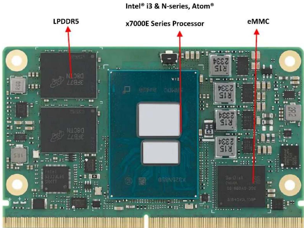
text_image
LPDDR5 Intel® i3 & N-series, Atom® x7000E Series Processor eMMCFigure 2.1 Board Chips ID – Front
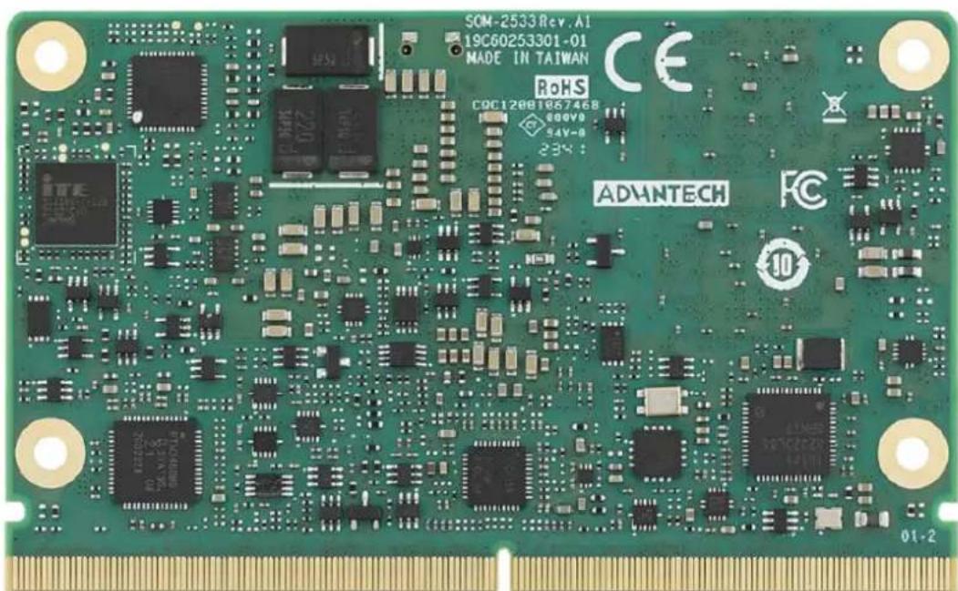
text_image
SOM-2533Rev.AI 19C60253301-01 MADE IN TAIWAN RoHS CQC12081857468 800V8 S4V-0 234- ADVNTECH 01-2Figure 2.2 Board Chips ID – Rear
2.2 Mechanical Diagrams
For more details on 2D/3D models, please look on the Advantech COM support service website: http://com.advantech.com
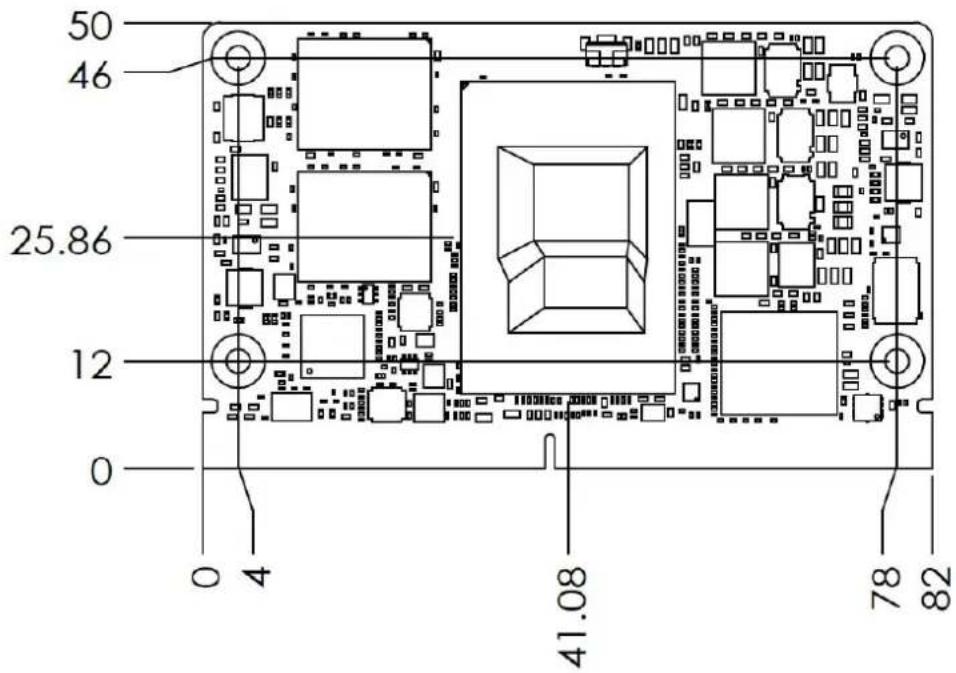
text_image
50 46 25.86 12 0 0 4 41.08 78 82Figure 2.3 Board Mechanical Diagram – Front

natural_image
Pure electrical circuit lines without any symbolsFigure 2.4 Board Mechanical Diagram – Rear
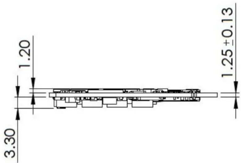
text_image
1.20 3.30 1.25±0.13Figure 2.5 Board Mechanical Diagram – Side
2.3 Assembly Diagram
These figures demonstrate the assembly order of the thermal module and COM module to the carrier board.
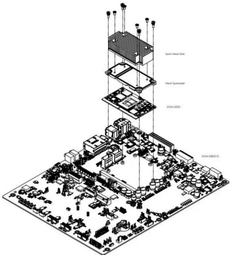
text_image
Semi HCCF Sink HCCF Synovcadier SOM-2533 SOM-DB2510Figure 2.6 Assembly Drawing
There are 4 reserved screw holes for SOM-2533 for pre-assembly of the heat spreader.
2.4 Assembly Drawing
There is a rubber solution implemented on the board to prevent the CPU from cracking. Please refer to the location of the rubber and consider the location when designing your carrier board.
Note! Advantech recommends that there not be any components on the top side of the carrier board module.

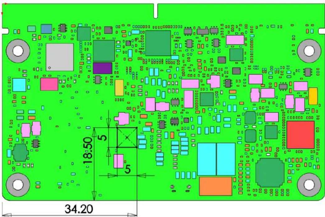
text_image
18.50 34.20Figure 2.7 Rubber Locations
Chapter 3
AMI BIOS
This chapter gives BIOS setup information for the SOM-2533 CPU Computer on Module.
Sections include:
Introduction
Entering Setup
Hot/Operation Key
■ Exiting the BIOS Setup Utility
3.1 Introduction
AMI BIOS has been integrated into many motherboards for over a decade. With the AMI BIOS Setup Utility, users can modify BIOS settings and control various system features. This chapter describes the basic navigation of the BIOS Setup Utility.
text_image
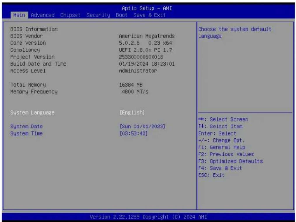
Aptio Setup - AMI Main Advanced Chipset Security Boot Save & Exit BIOS Information BIOS Vendor American Megatrends Core Version 5.0.2.6 0.23 x64 Compliancy UEFI 2.8.0; PI 1.7 Project Version 25330000060x018 Build Date and Time 01/19/2024 18:23:01 Access Level Administrator Total Memory 16384 MB Memory Frequency 4800 MT/s System Language [English] System Date [Sun 01/01/2023] System Time [03:53:43] Choose the system default language ++: Select Screen ↑↓: Select Item Enter: Select +/-: Change Opt. F1: General Help F2: Previous Values F3: Optimized Defaults F4: Save & Exit ESC: Exit Version 2.22.1239 Copyright (C) 2024 AMIFigure 3.1 Setup Program Initial Screen
AMI's BIOS ROM has a built-in setup program that allows users to modify the basic system configuration. This information is stored in flash ROM so it retains the setup information when the power is turned off.
3.2 Entering Setup
Turn on the computer and then press or
3.3 Main Setup
When users first enter the BIOS Setup Utility, users will enter the Main setup screen. Users can always return to the Main setup screen by selecting the Main tab. There are two Main Setup options. They are described in this section. The Main BIOS Setup screen is shown below.
| Main Advanced Chipset Security Boot Save & Exit | |
| BIOS Information BIOS Vendor American Megatrends Core Version 5.0.2.6 0.23 x64 Compliancy UEFI 2.8.0; PI 1.7 Project Version 25330000060X018 Build Date and Time 01/19/2024 18:23:01 Access Level Administrator | |
| Total Memory 16384 MB Memory Frequency 4800 MT/s | |
| System Language [English] | |
| System Date [Sun 01/01/2023] System Time [03:53:43] | |
| +:- Select Screen ↑↓: Select Item Enter: Select +/-: Change Opt. F1: General Help F2: Previous Values F3: Optimized Defaults F4: Save & Exit ESC: Exit | |
| Version 2.22.1239 Copyright (C) 2024 AMI |
Figure 3.2 Main Setup Screen
The Main BIOS setup screen has two main frames. The left frame displays all the options that can be configured. Grayed-out options cannot be configured; options in blue can. The right frame displays the key legend.
Above the key legend is an area reserved for a text message. When an option is selected in the left frame, it is highlighted in white. Often a text message will accompany it.
■ System Time / System Date
Use this option to change the system time and date. Highlight System Time or System Date using the
3.4 Advanced BIOS Features Setup
Select the Advanced tab from the SOM-2569 setup screen to enter the Advanced BIOS Setup screen. Users can select any item in the left frame of the screen, such as CPU Configuration, to go to the sub-menu for that item. Users can display an Advanced BIOS Setup option by highlighting it using the
| Aptio Setup - AMI Main Advanced Chipset Security Boot Save & Exit | |
| CPU Configuration Power & Performance PCH-FW Configuration Trusted Computing ACPI Settings Embedded Controller Serial Port Console Redirection USB Configuration Network Stack Configuration CSM Configuration SMARC GPIO Configuration Tls Auth Configuration Intel(R) Ethernet Controller I226-LM - 74:FE:48:86:EF:4E Intel(R) Ethernet Controller I226-LM - 74:FE:48:86:EF:4F | CPU Configuration Parameters |
| +: Select Screen 1↓: Select Item Enter: Select +/-: Change Opt. F1: General Help F2: Previous Values F3: Optimized Defaults F4: Save & Exit ESC: Exit | |
Figure 3.3 Advanced BIOS Features Setup Screen
■ CPU Configuration
CPU Configuration Parameters.
■ Power & Performance
Power & Performance Options.
■ PCH-FW Configuration
Configure Management Engine Technology Parameters.
■ Trusted Computing
Trusted Computing Settings.
■ ACPI Settings
ACPI Sleep State.
■ Embedded Controller
Embedded Controller Parameters.
Serial Port Console Redirection
Console Redirection Settings
USB Configuration
USB Configuration Parameters
■ Network Stack Configuration
Network Stack Settings
■ CSM Configuration CSM Configuration: Enable/Disable, Optional ROM execution settings, etc.
■ OEM Configuration
Advanced settings
■ Tls Auth Configuration
Press
Intel(R) Ethernet Controller I226-LM-74:FE:48:86:97:4E
Configure Gigabit Ethernet device parameters.
3.4.1 CPU Configuration
text_image
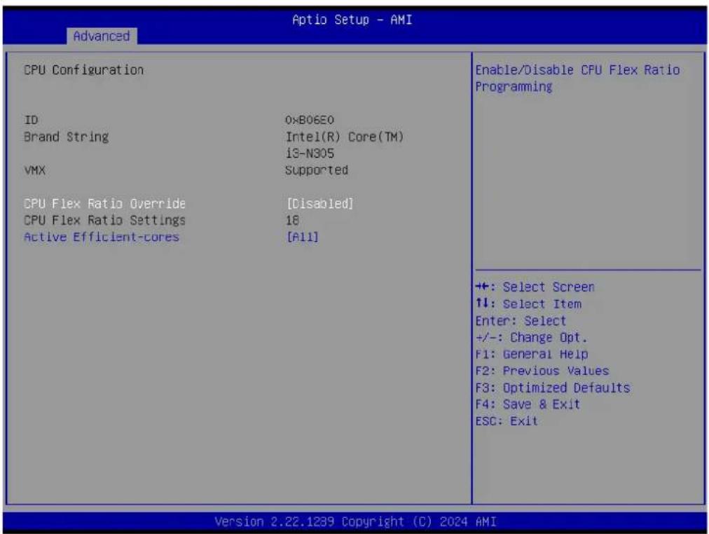
Advanced CPU Configuration ID 0xB06E0 Brand String:Intel(R) Core(TM) 13-N305 VMX Supported CPU Flex Ratio Override [Disabled] CPU Flex Ratio Settings 18 Active Efficient-cores [A11] Enable/Disable CPU Flex Ratio Programming ++: Select Screen ↑↓: Select Item Enter: Select +/-: Change Opt. F1: General Help F2: Previous Values F3: Optimized Defaults F4: Save & Exit ESC: Exit Version 2.22.1239 Copyright (C) 2024 AMIFigure 3.4 CPU Configuration
■ CPU Flex Ratio Override
Enable/Disable CPU Flex Ratio Programming.
■ Active Efficient-cores
Number of E-cores to enable in each processor package. Note: Number of Cores and E-cores are looked at together. When both are 0,0 , Pcode will enable all cores.
3.4.2 Power & Performance

text_image
Aptio Setup - AMI Advanced Power & Performance ►CPU - Power Management Control ►GT - Power Management Control CPU - Power Management Control Options ++: Select Screen ↑↓: Select Item Enter: Select +/-: Change Opt. F1: General Help F2: Previous Values F3: Optimized Defaults F4: Save & Exit ESC: Exit Version 2.22.1239 Copyright (C) 2024 AMIFigure 3.5 Power & Performance
■ CPU - Power Management Control
CPU - Power Management Control Options.
■ GT - Power Management Control
GT - Power Management Control Options.
3.4.2.1 CPU - Power Management Control
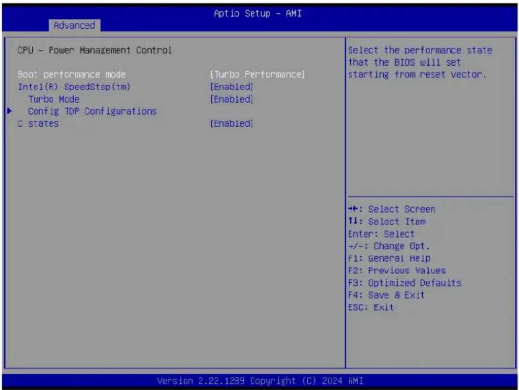
text_image
Advanced CPU - Power Management Control Boot performance mode [Turbo Performance] Intel(R) SpeedStep(1m) [Enabled] Turbo Mode [Enabled] Config TDP Configurations C states [Enabled] Select the performance state that the BIOS will set starting from reset vector. +:-: Select Screen ↑↓: Select Item Enter: Select +/-: Change Opt. F1: General Help F2: Previous Values F3: Optimized Defaults F4: Save & Exit ESC: Exit Version 2.22.1289 Copyright (C) 2024 AMIFigure 3.6 CPU - Power Management Control
■ Boot performance mode
Select the performance state that the BIOS will set starting from the reset vector.
Intel(R) SpeedStep(tm)
Allows more than two frequency ranges to be supported.
Turbo Mode
Enable/Disable processor Turbo Mode (requires EMTTM enabled too). AUTO means enabled.
■ Config TDP Configurations
Configurable Processor Base Power (cTDP) Configurations.
C states
Enable/Disable CPU Power Management. Allows CPU to go to C states when it's not 100% utilized.
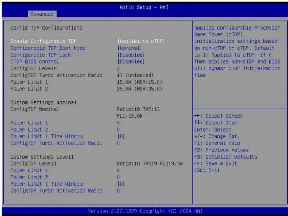
text_image
Aptio Setup - AMI Advanced Config TDP Configurations Enable Configurable TDF [Applies to cTDP] Configurable TDP Boot Mode [Nominal] Configurable TDP Lock [Disabled] CTDP BIOS control [Disabled] ConfigTDP Levels 2 ConfigTDP Turbo Activation Ratio 17 (Unlocked) Power Limit 1 15.0W (MSR:15.0) Power Limit 2 35.0W (MSR:35.0) Custom Settings Nominal ConfigTDP Nominal Ratio:18 TAR:17 PL1:15.0W Power Limit 1 0 Power Limit 2 0 Power Limit 1 Time Window [0] ConfigTDP Turbo Activation Ratio 0 Custom Settings Level1 ConfigTDP Level1 Ratio:10 TAR:9 PL1:9.0W Power Limit 1 0 Power Limit 2 0 Power Limit 1 Time Window [0] ConfigTDP Turbo Activation Ratio 0 Applies Configurable Processor Base Power (cTDP) initialization settings based on non-cTDP or cTDP. Default is 1: Applies to cTDP; if 0 then applies non-cTDP and BIOS will bypass cTDP initialization flow +: Select Screen ↑↓: Select Item Enter: Select +/-: Change Opt. F1: General Help F2: Previous Values F3: Optimized Defaults F4: Save & Exit ESC: Exit Version 2.22.1239 Copyright (C) 2024 AMIFigure 3.7 Config TDP Configurations
■ Enable Configurable TDP
Applies Configurable Processor Base Power (cTDP) initialization settings based on non-cTDP or cTDP. Default is 1: Applies to cTDP. If 0, then it applies non-cTDP. If 0, then non-cTDP and BIOS will bypass cTDP initialization flow.
- Configurable TDP Boot Mode
Configurable Processor Base Power (cTDP) Mode as Nominal/Level1/Level2/Deactivate TDP selection. The deactivate option will set MSR to Nominal and MMIO to Zero.
- Configurable TDP Lock
Configurable Processor Base Power (cTDP) Mode Lock sets the Lock bits on TURBO_ACTIVATION_RATIO and CONFIG_TDP_CONTROL. Note: When CTDP Lock is enabled, Custom ConfigTDP Count will be forced to 1 and Custom ConfigTDP Boot Index will be forced to 0.
CTDP BIOS control
Enable Configurable Processor Base Power (cTDP) control via runtime ACPI BIOS methods. This "BIOS only" feature does not require EC or driver support.
Power Limit 1
Power Limit1 in Milliwatts. BIOS will round to the nearest 1/8W when programming. 0=no custom override. For 12.50W, enter 12500. Overclocking SKU: Value must be between Max and Min Power Limits (specified by PACKAGE_POWER_SKU_MSR). Other SKUs: This value must be between Min Power Limit and the Processor Base Power (TDP) Limit.
Power Limit 2
Power Limit2 in milliwatts. BIOS will round to the nearest 1/8W when programming. 0=no custom override. For 12.50W, enter 12500. The processor applies control policies such that the package power does not exceed this limit.
■ Power Limit 1 Time Window
Power Limit 1 Time Window value in seconds. The value may vary from 0 to 128. 0=default value (28 sec for Mobile and 8 sec for Desktop). It defines the time window in which the Processor Base Power (TDP) value should be maintained.
■ ConfigTDP Turbo activation Ratio
Custom value for Turbo Activation Ratio. Needs to be configured with valid values from LFM to Max Turbo. 0 means it does not use a custom value.
Power Limit 1
Power Limit1 in milliwatts. BIOS will round to the nearest 1/8W when programming. 0=no custom override. For 12.50W, enter 12500. Overclocking SKU: Value must be between Max and Min Power Limits (specified by PACKAGE_POWER_SKU_MSR). Other SKUs: This value must be between Min Power Limit and the Processor Base Power (TDP) Limit.
Power Limit 2
Power Limit2 in milliwatts. BIOS will round to the nearest 1/8W when programming. 0=no custom override. For 12.50W, enter 12500. Processor applies control policies such that the package power does not exceed this limit.
■ Power Limit 1 Time Window
Power Limit 1 Time Window value in seconds. The value may vary from 0 to 128. 0=default value (28sec for Mobile and 8 sec for Desktop). It defines the time window in which the Processor Base Power (TDP) value should be maintained.
■ ConfigTDP Turbo activation Ratio
Custom value for Turbo Activation Ratio. Needs to be configured with valid values from LFM to Max Turbo. 0 means it does not use a custom value.
3.4.2.2 GT - Power Management Control

text_image
Optio Setup - AMI Advanced GT - Power Management Control RC6(Render Standby) [Enabled] Check to enable render standby support. +: Select Screen ↑↓: Select Item Enter: Select +/-: Change Opt. F1: General Help F2: Previous Values F3: Optimized Defaults F4: Save & Exit ESC: Exit Version 2.22.1239 Copyright (C) 2024 AMIFigure 3.8 GT - Power Management Control
RC6 (Render Standby)
Check to enable render standby support.
3.4.3 PCH-FW Configuration
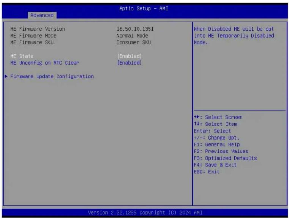
text_image
Optio Setup - AMI Advanced ME Firmware Version 16.50.10.1351 ME Firmware Mode Normal Mode ME Firmware SKU Consumer SKU ME State [Enabled] ME Unconfig on RTC Clear [Enabled] ► Firmware Update Configuration When Disabled ME will be put into ME Temporarily Disabled Mode. ++: Select Screen ↑↓: Select Item Enter: Select +/-: Change Opt. F1: General Help F2: Previous Values F3: Optimized Defaults F4: Save & Exit ESC: Exit Version 2.22.1239 Copyright (C) 2024 AMIFigure 3.9 PCH-FW Configuration
ME State
When Disabled, ME will be put into ME Temporarily Disabled Mode.
■ ME Unconfig on RTC Clear
When Disabled, ME will not be unconfigured on RTC clear.
■ Firmware Update Configuration
Configure Management Engine Technology Parameters.
3.4.3.1 Firmware Update Configuration

text_image
Aptio Setup - AMI Advanced Me FW Image Re-Flash [Disabled] FW Update [Enabled] Enable/Disable Me FW Image Re-Flash function. ++: Select Screen 1↓: Select Item Enter: Select +/-: Change Opt. F1: General Help F2: Previous Values F3: Optimized Defaults F4: Save & Exit ESC: Exit Version 2.22.1239 Copyright (C) 2024 AMIFigure 3.10 Firmware Update Configuration
■ Me FW Image Re-Flash
Enable/Disable Me FW Image Re-Flash function.
FW Update
Enable/Disable ME FW Update function.
3.4.4 Trusted Computing
| Aptio Setup - AMI Advanced | |
| TPM 2.0 Device Found Firmware Version: 600.13 Vendor: INTC Security Device Support [Enable] Active PCR banks SHA255 Available PCR banks SHA255,SHA384,SM3 SHA256 PCR Bank [Enabled] SHA384 PCR Bank [Disabled] SM3_256 PCR Bank [Disabled] | |
| Pending operation [None] Platform Hierarchy [Enabled] Storage Hierarchy [Enabled] Endorsement Hierarchy [Enabled] Physical Presence Spec Version [1.3] TPM 2.0 InterfaceType [CRB] Device Select [Auto] | Enables or Disables BIOS support for security device. O.S. will not show Security Device. TCG EFI protocol and INT1A interface will not be available. |
| +: Select Screen ↑↓: Select Item Enter: Select +/-: Change Opt. F1: General Help F2: Previous Values F3: Optimized Defaults F4: Save & Exit ESC: Exit | |
Figure 3.11 Trusted Computing
■ Security Device Support
Enable/Disable BIOS support for a security device. The OS will not show the security device. TCG EFI protocol and INT1A interface will not be available.
SHA256 PCR Bank
Enable/Disable SHA256 PCR Bank.
SHA384 PCR Bank
Enable/Disable SHA384 PCR Bank.
SM3_256 PCR Bank
Enable/Disable SM3_256 PCR Bank.
■ Pending operation
Schedule an operation for the Security Device. NOTE: Your computer will reboot during restart in order to change the state of the security device.
Platform Hierarchy
Enable/Disable Platform Hierarchy.
Storage Hierarchy
Enable/Disable Storage Hierarchy.
■ Endorsement Hierarchy
Enable/Disable Endorsement Hierarchy.
■ Physical Presence Spec Version
Select to tell the OS to support PPI Spec Version 1.2 or 1.3. Note some HCK tests might not support 1.3.
TPM 2.0 Interface Type
Device Select
TPM 1.2 will restrict support to TPM 1.2 devices; TPM 2.0 will restrict support to TPM 2.0 devices; Auto will support both with the default set to TPM 2.0 devices if not found; TPM 1.2 devices will be enumerated.
3.4.5 ACPI Settings

text_image
Advanced Aptio Setup - AMI ACPI Settings Enable ACPI Auto Configuration [Disabled] Enable Hibernation [Enabled] ACPI Sleep State [S3 (Suspend to RAM)] Enables or Disables BIOS ACPI Auto Configuration. +: Select Screen ↑↓: Select Item Enter: Select +/-: Change Opt. F1: General Help F2: Previous Values F3: Optimized Defaults F4: Save & Exit ESC: Exit Version 2.22.1239 Copyright (C) 2024 AMIFigure 3.12 ACPI Settings
■ Enable ACPI Auto Configuration
Enable/Disable BIOS ACPI Auto Configuration.
■ Enable Hibernation
Enable/Disable System ability to Hibernate (OS/S4 Sleep State). This option may be not effective with some OS.
ACPI Sleep State
Select the highest ACPI sleep state the system will enter when the SUSPEND button is pressed.
3.4.6 Embedded Controller
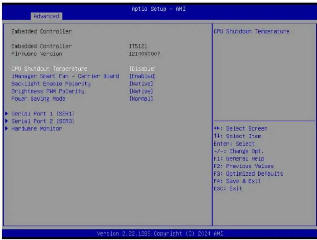
text_image
Advanced Embedded Controller Embedded Controller IT5121 Firmware Version I2140X0007 CPU Shutdown Temperature [Disable] iManager Smart Fan - Carrier Board [Enabled] Backlight Enable Polarity [Native] Brightness PWM Polarity [Native] Power Saving Mode [Normal] ► Serial Port 1 (SER1) ► Serial Port 2 (SER3) ► Hardware Monitor CPU Shutdown Temperature +: Select Screen ↑↓: Select Item Enter: Select +/-: Change Opt. F1: General Help F2: Previous Values F3: Optimized Defaults F4: Save & Exit ESC: Exit Version 2.22.1239 Copyright (C) 2024 AMIFigure 3.13 Embedded Controller
■ CPU Shutdown Temperature
CPU Shutdown Temperature.
■ iManager Smart Fan - Carrier Board
Control Carrier Board Smart FAN function. Get value from EC and only set the value when you save changes.
■ Backlight Enable Polarity
Switch Backlight Enable Polarity to Native or Invert.
■ Brightness PWM Polarity
Backlight Control Brightness PWM Polarity for Native or Invert.
Power Saving Mode
Select Power Saving Mode.
Serial Port 1 (SER1)
Set Parameters of Serial Port 1 (SMARC SER1).
Serial Port 2 (SER3)
Set Parameters of Serial Port 2 (SMARC SER3).
Hardware Monitor
Monitor hardware status.
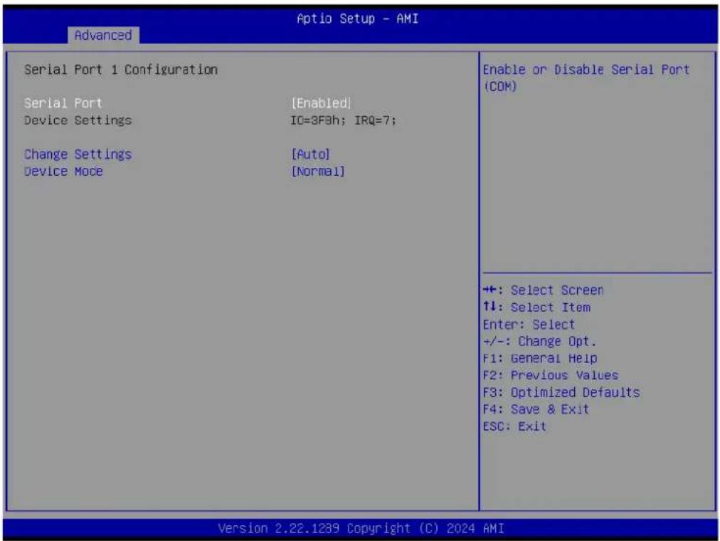
3.4.6.1 Serial Port 1 Configuration
text_image
Advanced Optio Setup - AMI Serial Port 1 Configuration Serial Port [Enabled] Device Settings IO=3F3h; IRQ=7; Change Settings [Auto] Device Mode [Normal] Enable or Disable Serial Port (COM) +: Select Screen ↑↓: Select Item Enter: Select +/-: Change Opt. F1: General Help F2: Previous Values F3: Optimized Defaults F4: Save & Exit ESC: Exit Version 2.22.1289 Copyright (C) 2024 AMIFigure 3.14 Serial Port 1 Configuration
Serial Port
Enable/Disable Serial Port (COM).
■ Change Settings
Select optimal settings for a Super IO Device.
■ Device Mode
Change the Serial Port Mode.
3.4.6.2 Serial Port 2 Configuration
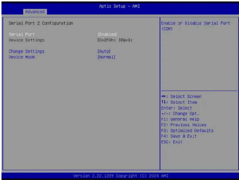
text_image
Advanced Aptio Setup - AMI Serial Port 2 Configuration Serial Port [Enabled] Device Settings IC=2F3h; IRQ=3; Change Settings [Auto] Device Mode [Normal] Enable or Disable Serial Port (COM) +: Select Screen ↑↓: Select Item Enter: Select +/-: Change Opt. F1: General Help F2: Previous Values F3: Optimized Defaults F4: Save & Exit ESC: Exit Version 2.22.1239 Copyright (C) 2024 AMIFigure 3.15 Serial Port 2 Configuration
Serial Port
Enable/Disable Serial Port (COM).
■ Change Settings
Select optimal settings for a Super IO Device.
■ Device Mode
Change the Serial Port Mode.
3.4.6.3 Hardware Monitor

text_image
Advanced Aptio Setup - AMI PC Health Status CPU temperature : +44°C/ +111°F Carrier Board FAN : 0 RPM +VBAT : +3.142 V +Vin : +4.344 V +: Select Screen ↑↓: Select Item Enter: Select +/-: Change Opt. F1: General Help F2: Previous Values F3: Optimized Defaults F4: Save & Exit ESC: Exit Version 2.22.1289 Copyright (C) 2024 AMIFigure 3.16 Hardware Monitor
3.4.7 Serial Port Console Redirection
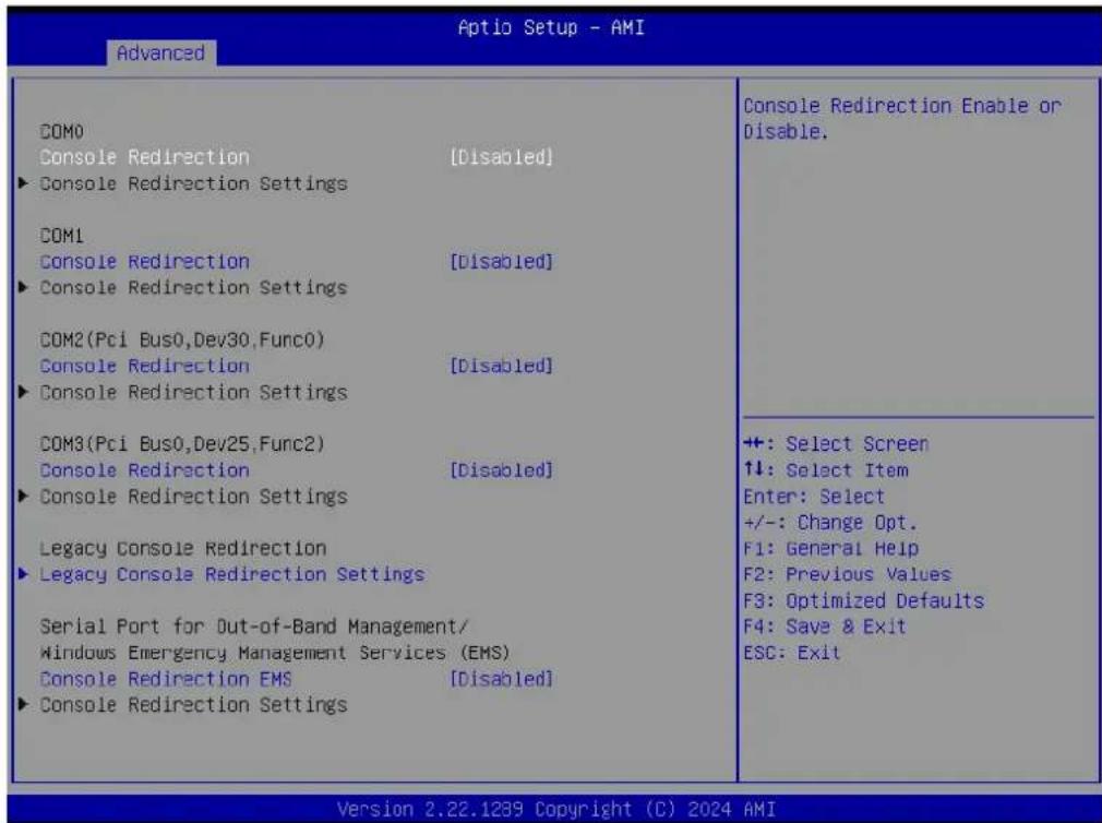
text_image
Aptio Setup - AMI Advanced COM0 Console Redirection [Disabled] ► Console Redirection Settings COM1 Console Redirection [Disabled] ► Console Redirection Settings COM2(Pci Bus0,Dev30,Func0) Console Redirection [Disabled] ► Console Redirection Settings COM3(Pci Bus0,Dev25,Func2) Console Redirection [Disabled] ► Console Redirection Settings Legacy Console Redirection ► Legacy Console Redirection Settings Serial Port for Out-of-Band Management/ Windows Emergency Management Services (EMS) Console Redirection EMS [Disabled] ► Console Redirection Settings Console Redirection Enable or Disable. +: Select Screen ↑↓: Select Item Enter: Select +/-: Change Opt. F1: General Help F2: Previous Values F3: Optimized Defaults F4: Save & Exit ESC: Exit Version 2.22.1239 Copyright (C) 2024 AMIFigure 3.17 Serial Port Console Redirection
■ Console Redirection
Enable/Disable Console Redirection.
■ Legacy Console Redirection Settings
Legacy Console Redirection Settings.
■ Console Redirection EMS
Enable/Disable Console Redirection.
3.4.8 USB Configuration
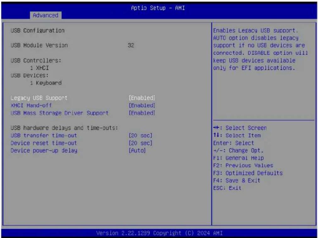
text_image
Advanced Optio Setup - AMI USB Configuration USB Module Version 32 USB Controllers: 1 XHCI USB Devices: 1 Keyboard Legacy USE Support [Enabled] XHCI Hand-off [Enabled] USB Mass Storage Driver Support [Enabled] USB hardware delays and time-outs: USB transfer time-out [20 sec] Device reset time-out [20 sec] Device power-up delay [Auto] Enables Legacy USB support. AUTO option disables legacy support if no USB devices are connected. DISABLE option will keep USB devices available only for EFI applications. ++: Select Screen ↑↓: Select Item Enter: Select +/-: Change Opt. F1: General Help F2: Previous Values F3: Optimized Defaults F4: Save & Exit ESC: Exit Version 2.22.1239 Copyright (C) 2024 AMIFigure 3.18 USB Configuration
Legacy USB Support
Enables Legacy USB support. The AUTO option disables legacy support if no USB devices are connected. The Disable option will keep USB devices available only for EFI applications.
XHCI Hand-off
This is a workaround for OS without XHCI hand-off support. The XHCI ownership change should be claimed by the XHCI driver.
USB Mass Storage Driver Support
Enable/Disable USB Mass Storage Driver Support.
USB transfer time-out
The time-out value for Control, Bulk, and Interrupt transfers.
■ Device reset time-out
USB mass storage device Start Unit command time-out.
■ Device power-up delay
Maximum time the device will take before it properly reports itself to the Host Controller. 'Auto' uses the default value: for a Root port it is 100 ms, for a Hub port the delay is taken from the Hub descriptor.
3.4.9 Network Stack Configuration
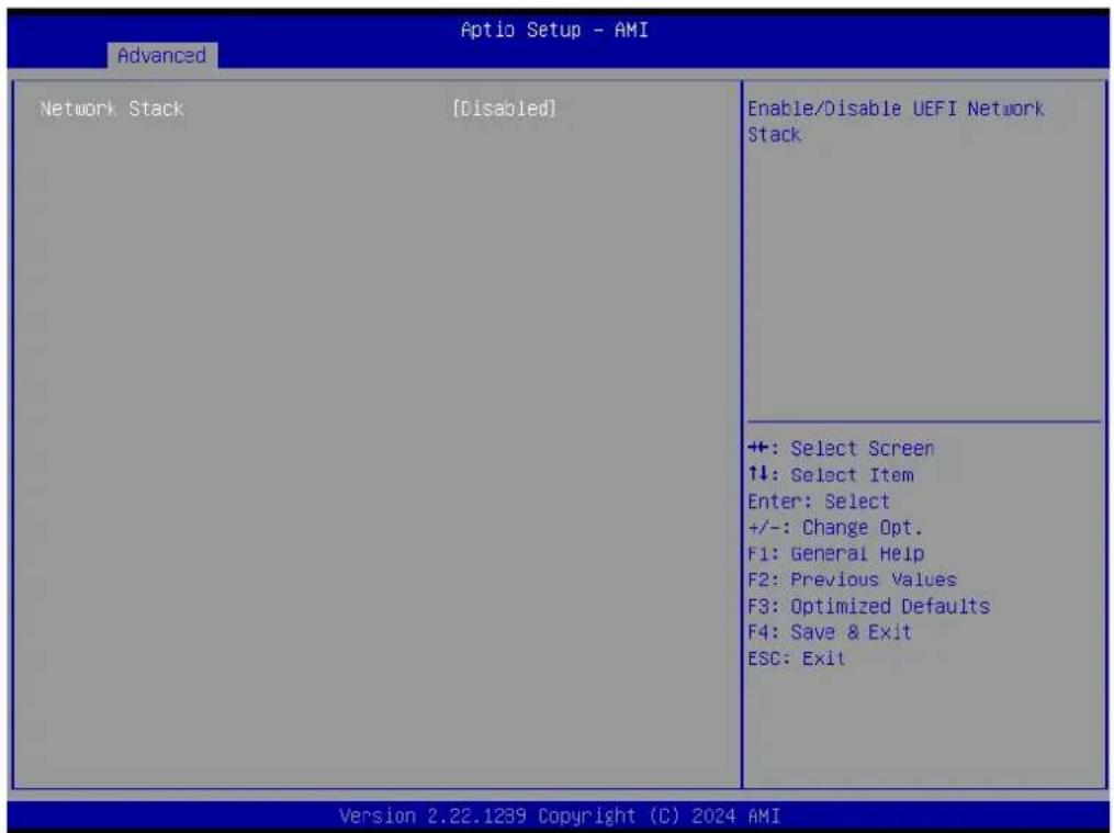
text_image
Advanced Aptio Setup - AMI Network Stack [Disabled] Enable/Disable UEFI Network Stack ++: Select Screen ↑↓: Select Item Enter: Select +/-: Change Opt. F1: General Help F2: Previous Values F3: Optimized Defaults F4: Save & Exit ESC: Exit Version 2.22.1239 Copyright (C) 2024 AMIFigure 3.19 Network Stack Configuration
Network Stack
Enable/Disable the UEFI Network Stack.
3.4.10 Compatibility Support Module Configuration

text_image
Aptio Setup - AMI Advanced Compatibility Support Module Configuration CSM Support [Disabled] Enable/Disable CSM Support. +: Select Screen ↑↓: Select Item Enter: Select +/-: Change Opt. F1: General Help F2: Previous Values F3: Optimized Defaults F4: Save & Exit ESC: Exit Version 2.22.1239 Copyright (C) 2024 AMIFigure 3.20 Compatibility Support Module Configuration
CSM Support
Enable/Disable CSM Support.
3.4.11 SMARC GPIO Configuration
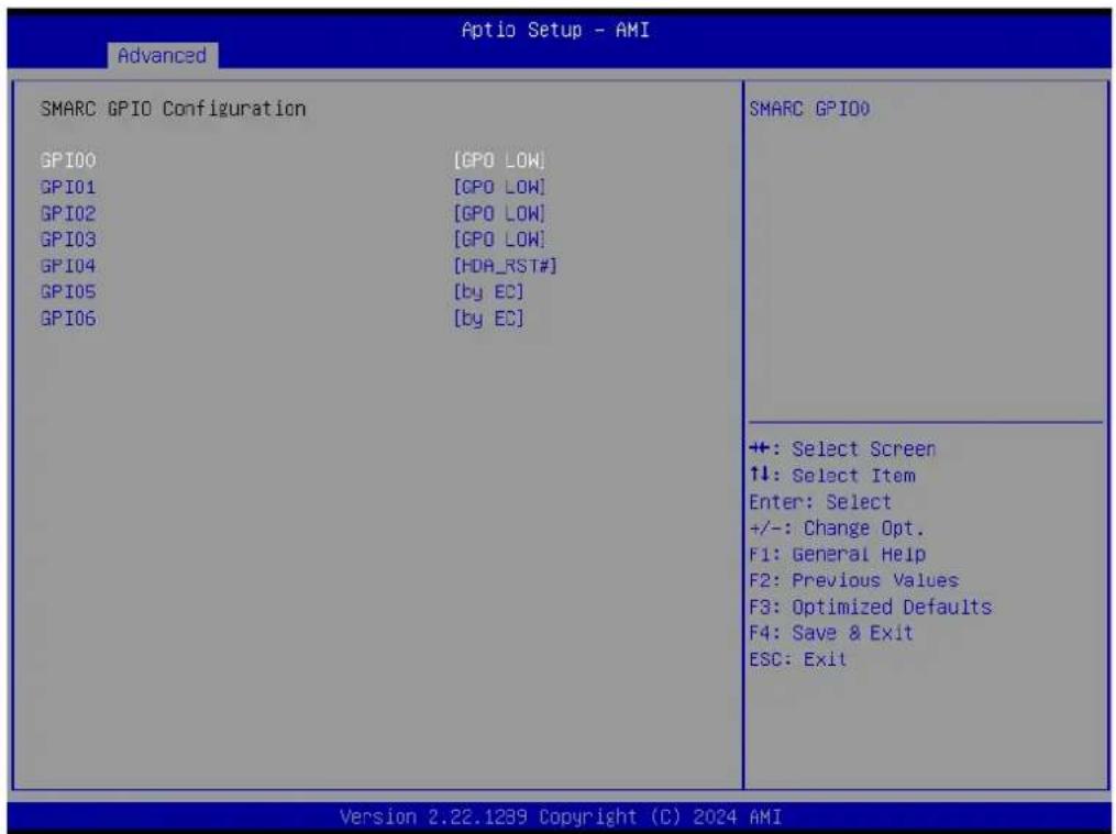
text_image
Optio Setup - AMI Advanced SMARC GPIO Configuration GPI00 [GPO LOW] GPI01 [GPO LOW] GPI02 [GPO LOW] GPI03 [GPO LOW] GPI04 [HDA_RST#] GPI05 [by EC] GPI06 [by EC] SMARC GPIO +: Select Screen ↑↓: Select Item Enter: Select +/-: Change Opt. F1: General Help F2: Previous Values F3: Optimized Defaults F4: Save & Exit ESC: Exit Version 2.22.1239 Copyright (C) 2024 AMIFigure 3.21 SMARC GPIO Configuration
■ GPIO0
SMARC GPIO0.
■ GPIO1
SMARC GPIO1.
■ GPIO2
SMARC GPIO2.
■ GPIO3
SMARC GPIO3.
■ GPIO4
SMARC GPIO4.
■ GPIO5
SMARC GPIO5.
■ GPIO6
SMARC GPIO6.
3.5 Chipset Setup

text_image
Aptio Setup - AMI Main Advanced Chipset Security Boot Save & Exit System Agent (SA) Configuration PCH-IO Configuration System Agent (SA) Parameters +: Select Screen ↑↓: Select Item Enter: Select +/-: Change Opt. F1: General Help F2: Previous Values F3: Optimized Defaults F4: Save & Exit ESC: Exit Version 2.22.1239 Copyright (C) 2024 AMIFigure 3.22 Chipset Setup
System Agent (SA) Configuration System Agent Parameters.
■ PCH-I0 Configuration
PCH parameters.
3.5.1 System Agent (SA) Configuration

text_image
Chipset System Agent (SA) Configuration VT-d Supported ► Memory Configuration ► Graphics Configuration VT-d [Enabled] Above 4GB MMIO BIOS assignment [Enabled] Memory Configuration Parameters +: Select Screen ↑↓: Select Item Enter: Select +/-: Change Opt. F1: General Help F2: Previous Values F3: Optimized Defaults F4: Save & Exit ESC: Exit Version 2.22.1239 Copyright (C) 2024 AMIFigure 3.23 System Agent (SA) Configuration
■ Memory Configuration
Memory Configuration Parameters.
■ Graphic Configuration Graphics Configuration.
■ VT-d
VT-d capability.
- Above 4GB MMIO BIOS assignment
Enable/Disable above 4GB memory mapped IO BIOS assignment. This is enabled automatically when the aperture size is set to 2048MB.
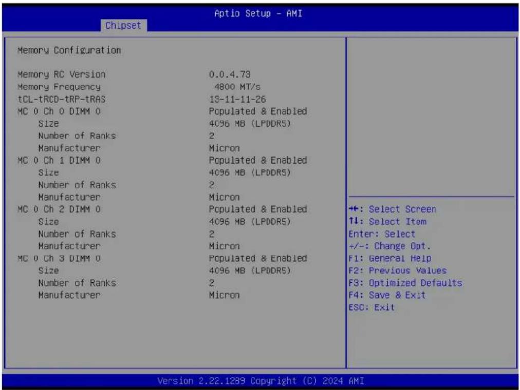
3.5.1.1 Memory Configuration
text_image
Chipset Aptio Setup - AMI Memory Configuration Memory RC Version 0.0.4.73 Memory Frequency 4800 MT/s tCL-tRCD-tRP-tRAS 13-11-11-26 MC 0 Ch 0 DIMM 0 Populated & Enabled Size 4096 MB (LPDDR5) Number of Ranks 2 Manufacturer Micron MC 0 Ch 1 DIMM 0 Populated & Enabled Size 4096 MB (LPDDR5) Number of Ranks 2 Manufacturer Micron MC 0 Ch 2 DIMM 0 Populated & Enabled Size 4096 MB (LPDDR5) Number of Ranks 2 Manufacturer Micron MC 0 Ch 3 DIMM 0 Populated & Enabled Size 4096 MB (LPDDR5) Number of Ranks 2 Manufacturer Micron ++: Select Screen ↑↓: Select Item Enter: Select +/-: Change Opt. F1: General Help F2: Previous Values F3: Optimized Defaults F4: Save & Exit ESC: Exit Version 2.22.1239 Copyright (C) 2024 AMIFigure 3.24 Memory Configuration
3.5.1.2 Graphics Configuration
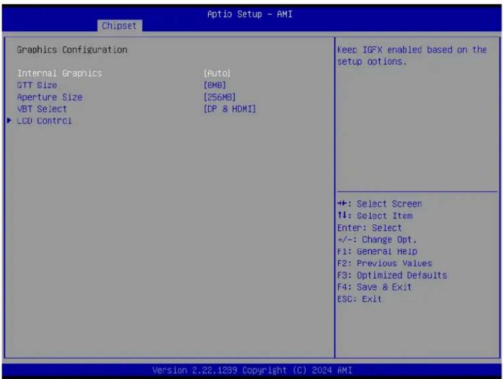
text_image
Aptio Setup - AMI Chipset Graphics Configuration Internal Graphics [Auto] GTT Size [6MB] Aperture Size [256MB] VBT Select [DP & HDMI] LCD Control Keep IGFX enabled based on the setup options. +: Select Screen 1: Select Item Enter: Select +/-: Change Opt. F1: General Help F2: Previous Values F3: Optimized Defaults F4: Save & Exit ESC: Exit Version 2.22.1239 Copyright (C) 2024 AMIFigure 3.25 Graphics Configuration
Internal Graphics
Keep IGFX enabled based on the setup options.
GTT Size
Select the GTT size.
Aperture Size
Select the aperture size. Note: Above 4GB MMIO BIOS assignment is atomically enabled when selecting a 2048MB aperture. To use this feature, please disable CSM support.
VBT Select
Select VBT for GOP Driver Select Vbt to MIPI if any of the Display has MIPI
LCD Control
LCD control.
LCD Control

text_image
Aptio Setup - AMI Chipset LCD Control NXP non-EDID Support [Enabled] Color depth and packing format [JEIDA or VESA (18 bpp)] Dual LVDS mode [Single LVDS bus mode] LCD Panel Type [800x800] LVDS clock spreading [no spreading] LVDS suing level [300 mV] Panel Scaling [Auto] NXP PTN3450 Support: Enable: Used internal EDID setting; Disable: Get EDID from DDC bus. +: Select Screen ↑↓: Select Item Enter: Select +/-: Change Opt. F1: General Help F2: Previous Values F3: Optimized Defaults F4: Save & Exit ESC: Exit Version 2.22.1239 Copyright (C) 2024 AMIFigure 3.26 LCD Control
- NXP non-EDID Support
NXP PTN3460 Support: Enabled: Used internal EDID setting; Disabled: Get EDID from DDC bus.
– Color depth and packing format
Color depth and packing format.
- Dual LVDS mode
Dual LVDS Mode.
- LCD Panel Type
Select LCD panel used by Internal Graphics Device by selecting the appropriate setup item.
- LVDS Clock Spreading
LVDS Clock Spreading.
- LVDS Swing Level
LVDS Swing Level.
- Panel Scaling
Select the LCD panel scaling option used by the Internal Graphics Device.
3.5.2 PCH-IO Configuration

text_image
Aptio Setup - AMI Chipset PCH-IO Configuration PCI Express Configuration SATA Configuration USB Configuration Security Configuration HD Audio Configuration SerialIo Configuration SCS Configuration State After G3 [S5 State] Pcie Ref P11 SSC [Auto] Flash Protection Range Registers [Disabled] (FPRR) SPD Write Disable [TRUE] PCI Express Configuration settings +: Select Screen ↑↓: Select Item Enter: Select +/-: Change Opt. F1: General Help F2: Previous Values F3: Optimized Defaults F4: Save & Exit ESC: Exit Version 2.22.1239 Copyright (C) 2024 AMIFigure 3.27 PCH-IO Configuration
PCI Express Configuration
PCI Express Configuration settings.
■ SATA Configuration
SATA device option settings.
USB Configuration
USB Configuration settings.
■ Security Configuration
Security Configuration settings.
■ HD Audio Configuration
HD audio subsystem configuration settings.
Seriallo Configuration
Seriallo configuration settings.
■ SCS Configuration
Storage and Communication Subsystem (SCS) Configuration.
3.5.2.1 PCI Express Configuration
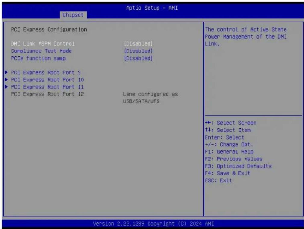
text_image
Aptio Setup - AMI Chipset PCI Express Configuration DMI Link ASPM Control [Disabled] Compliance Test Mode [Disabled] PCIe function swap [Disabled] ► PCI Express Root Port 9 ► PCI Express Root Port 10 ► PCI Express Root Port 11 PCI Express Root Port 12 Lane configured as USB/SATA/UFS The control of Active State Power Management of the DMI Link. +: Select Screen ↑↓: Select Item Enter: Select +/-: Change Opt. F1: General Help F2: Previous Values F3: Optimized Defaults F4: Save & Exit ESC: Exit Version 2.22.1239 Copyright (C) 2024 AMIFigure 3.28 PCI Express Configuration
■ DMI Link ASPM Control
The control of Active State Power Management of the DMI Link.
■ Compliance Test Mode
Enable when using the Compliance Load Board.
PCIe function swap
When Disabled, it prevents PCIE rootport function swap. If any function other than 0th is enabled, 0th will become visible.
PCI Express Root Port 9
PCI Express Root Port Settings.
PCI Express Root Port 10
PCI Express Root Port Settings.
PCI Express Root Port 11
PCI Express Root Port Settings.
PCI Express Root Port 9
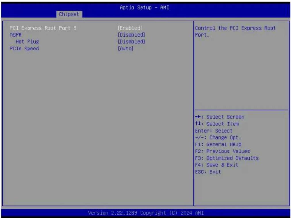
text_image
Aptio Setup - AMI Chipset PCI Express Root Port 9 [Enabled] ASPM [Disabled] Hot Plug [Disabled] PCIe Speed [Auto] Control the PCI Express Root Port. +:-: Select Screen ↑↓: Select Item Enter: Select +/-: Change Opt. F1: General Help F2: Previous Values F3: Optimized Defaults F4: Save & Exit ESC: Exit Version 2.22.1289 Copyright (C) 2024 AMIFigure 3.29 PCI Express Root Port 9
- PCI Express Root Port 9
Control the PCI Express Root Port. - ASPM
Set the ASPM Level: Force L0s – Force all links to L0s State AUTO – BIOS auto configure DISABLE – Disables ASPM. - Hot Plug
PCI Express Hot Plug Enable/Disable. - PCIe Speed
Configure PCIe Speed.
3.5.2.2 SATA Configuration

text_image
Aptio Setup - AMI Chipset SATA Configuration SATA Controller(s) [Enabled] SATA Controller Speed [Default] Serial ATA Port 0 Empty Software Preserve Unknown Port 0 [Enabled] Serial ATA Port 1 Empty Software Preserve Unknown Port 1 [Enabled] Enable/Disable SATA Device. +: Select Screen ↑↓: Select Item Enter: Select +/-: Change Opt. F1: General Help F2: Previous Values F3: Optimized Defaults F4: Save & Exit ESC: Exit Version 2.22.1239 Copyright (C) 2024 AMIFigure 3.30 SATA Configuration
■ SATA Controller(s)
Enable/Disable SATA Device.
■ SATA Controller Speed
Indicates the maximum speed the SATA controller can support.
Port 0
Enable/Disable SATA Port.
Port 1
Enable/Disable SATA Port.
3.5.2.3 USB Configuration

text_image
Chipset Aptio Setup - AMI USB Configuration xDCI Support [Enabled] USB Port Disable Override [Disable] Enable/Disable xDCI (USB OTG Device). +:-: Select Screen ↑↓: Select Item Enter: Select +/-: Change Opt. F1: General Help F2: Previous Values F3: Optimized Defaults F4: Save & Exit ESC: Exit Version 2.22.1239 Copyright (C) 2024 AMIFigure 3.31 USB Configuration
xDCI Support
Enable/Disable xDCI (USB OTG Device).
USB Port Disable Override
Selectively Enable/Disable the corresponding USB port from reporting a Device Connection to the controller.
3.5.2.4 Security Configuration

text_image
Aptio Setup - AMI Chipset Security Configuration BIOS Lock [Enabled] Force unlock on all GPIO pads [Disabled] Enable/Disable the PCH BIOS Lock Enable feature. Required to be enabled to ensure SMM protection of flash. +: Select Screen 1↓: Select Item Enter: Select +/-: Change Opt. F1: General Help F2: Previous Values F3: Optimized Defaults F4: Save & Exit ESC: Exit Version 2.22.1239 Copyright (C) 2024 AMIFigure 3.32 Security Configuration
BIOS Lock
Enable/Disable the PCH BIOS Lock Enable feature. It is required to be enabled to ensure SMM protection of flash.
■ Force unlock on all GPIO pads
If Enabled, BIOS will force all GPIO pads to be in the unlocked state.
3.5.2.5 HD Audio Subsystem Configuration Settings
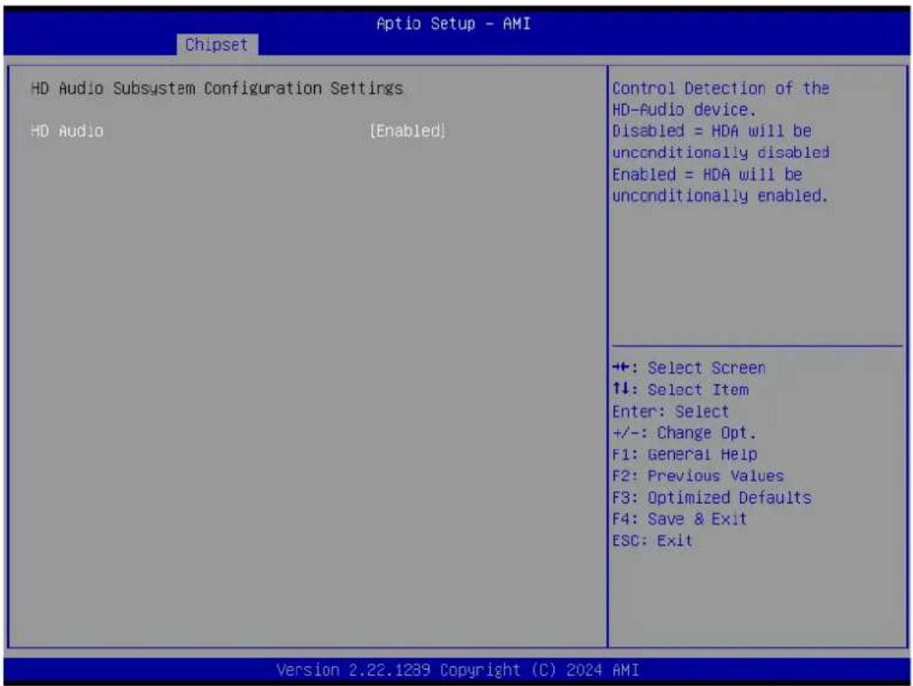
text_image
Aptio Setup - AMI Chipset HD Audio Subsystem Configuration Settings HD Audio [Enabled] Control Detection of the HD-Audio device. Disabled = HDA will be unconditionally disabled Enabled = HDA will be unconditionally enabled. +: Select Screen 14: Select Item Enter: Select +/-: Change Opt. F1: General Help F2: Previous Values F3: Optimized Defaults F4: Save & Exit ESC: Exit Version 2.22.1239 Copyright (C) 2024 AMIFigure 3.33 HD Audio Subsystem Configuration Settings
HD Audio
Control Detection of the HD-Audio device. Disabled=HDA will be unconditionally disabled. Enabled=HDA will be unconditionally enabled.
3.5.2.6 Seriallo Configuration
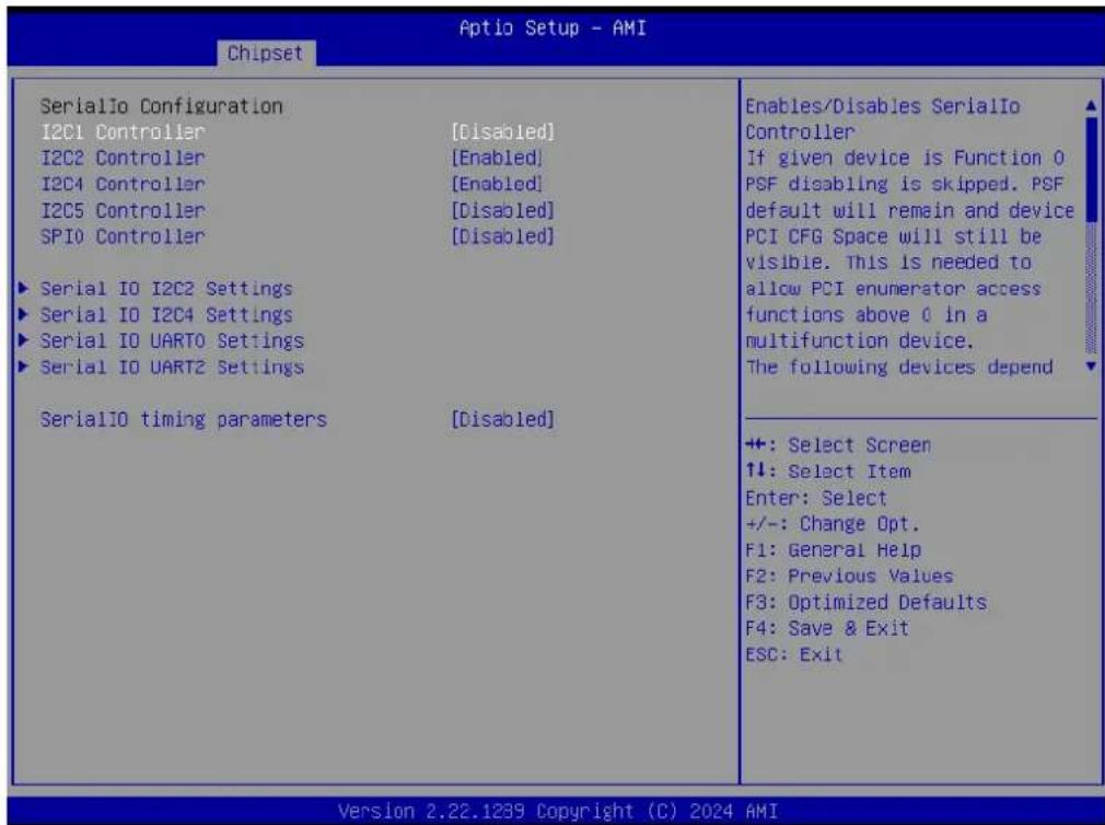
text_image
Aptio Setup - AMI Chipset SerialIO Configuration I2C1 Controller [Disabled] I2C2 Controller [Enabled] I2C4 Controller [Enabled] I2C5 Controller [Disabled] SPI0 Controller [Disabled] ► Serial IO I2C2 Settings ► Serial IO I2C4 Settings ► Serial IO UART0 Settings ► Serial IO UART2 Settings SerialIO timing parameters [Disabled] Enables/Disables SerialIo Controller If given device is Function 0 PSF disabling is skipped. PSF default will remain and device PCI CFG Space will still be visible. This is needed to allow PCI enumerator access functions above 0 in a multifunction device. The following devices depend +: Select Screen ↑↓: Select Item Enter: Select +/-: Change Opt. F1: General Help F2: Previous Values F3: Optimized Defaults F4: Save & Exit ESC: Exit Version 2.22.1289 Copyright (C) 2024 AMIFigure 3.34 Seriallo Configuration
I2C1 Controller
Enable/Disable the Seriallo Controller.
If the given device Function 0 PSF disabling is skipped, PSF default will remain and the device PCI CFG Space will still be visible. This is needed to allow PCI enumerator access functions above 0 in a multifunction device.
The following devices depend on each other:
I2C0 and I2C1,2,3
UART0 and UART1, SPI0, 1
UART2 and I2C4,5
UART 0 (00:30:00) cannot be disabled when:
- Child device is enabled like CNVi Bluetooth (_SB.PC00.UA00.BTH0)
UART 0 (00:30:00) cannot be enabled when:
- I2S Audio codec is enabled (_SB.PC00.I2C0.HDAC)
I2C2 Controller
Enable/Disable the Seriallo Controller.
If the given device Function 0 PSF disabling is skipped, PSF default will remain and device PCI CFG Space will still be visible. This is needed to allow PCI enumerator access functions above 0 in a multifunction device.
The following devices depend on each other:
I2C0 and I2C1,2,3
UART0 and UART1,SPI0,1
UART2 and I2C4,5
UART 0 (00:30:00) cannot be disabled when:
- Child device is enabled like CNVi Bluetooth (_SB.PC00.UA00.BTH0)
UART 0 (00:30:00) cannot be enabled when:
- I2S Audio codec is enabled (_SB.PC00.I2C0.HDAC)
I2C4 Controller
Enable/Disable the Seriallo Controller For I2C5 and UART2; to work, this device has to be enabled.
I2C5 Controller
Enable/Disable the Seriallo Controller. For this device to work, I2C4 has to be enabled.
■ SPIO Controller
Enable/Disable the Seriallo Controller.
If the given device Function 0 PSF disabling is skipped, PSF default will remain and the device PCI CFG Space will still be visible. This is needed to allow PCI enumerator access functions above 0 in a multifunction device.
The following devices depend on each other:
I2C0 and I2C1,2,3
UART0 and UART1, SPI0, 1
UART2 and I2C4,5
UART 0 (00:30:00) cannot be disabled when:
- The Child device is enabled like CNVi Bluetooth (_SB.PC00.UA00.BTH0)
UART 0 (00:30:00) cannot be enabled when:
- I2S Audio codec is enabled (_SB.PC00.I2C0.HDAC)
Serial IO I2C2 Settings
Configure Seriallo Controller.
Serial IO I2C4 Settings
Configure Seriallo Controller.
Serial IO UART0 Settings
Configure Seriallo Controller.
Serial IO UART2 Settings
Configure Seriallo Controller.
SerialIO timing parameters
Enables additional timing parameters for all Seriallo controllers. Defaults can be changed in each controller setting. A platform restart is required to apply changes.
Serial IO I2C2 Settings

text_image
Aptio Setup - AMI Chipset Serial IO I2C2 Settings Timing parameters disabled ++: Select Screen ↑↓: Select Item Enter: Select +/-: Change Opt. F1: General Help F2: Previous Values F3: Optimized Defaults F4: Save & Exit ESC: Exit Version 2.22.1239 Copyright (C) 2023 AMIFigure 3.35 Serial IO I2C2 Settings
Serial IO I2C4 Settings
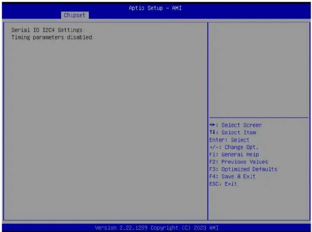
text_image
Aptio Setup - AMI Chipset Serial IO I2C4 Settings Timing parameters disabled ++ : Select Screen 1↓: Select Item Enter: Select +/-: Change Opt. F1: General Help F2: Previous Values F3: Optimized Defaults F4: Save & Exit ESC: Exit Version 2.22.1239 Copyright (C) 2023 AMIFigure 3.36 Serial IO I2C4 Settings
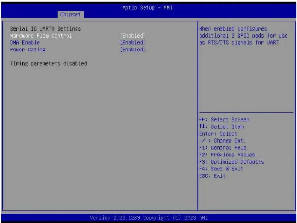
Serial IO UART0 Settings
text_image
Aptio Setup - AMI Chipset Serial IO UARTO Settings Hardware Flow Control [Enabled] DMA Enable [Enabled] Power Gating [Enabled] Timing parameters disabled When enabled configures additional 2 GPIO pads for use as RTS/CTS signals for UART +:-: Select Screen ↑↓: Select Item Enter: Select +/-: Change Opt. F1: General Help F2: Previous Values F3: Optimized Defaults F4: Save & Exit ESC: Exit Version 2.22.1239 Copyright (C) 2023 AMIFigure 3.37 Serial IO UART0 Settings
- Hardware Flow Control
Enabled: it configures additional 2 GPIO pads for use as RTS/CTS signals for UART.
- DMA Enable
Enabled, the UART OS driver will use DMA when possible. Disabled: the OS driver will enforce PI0 mode.
- Power Gating
Disabled: No _PS0 _PS3 support, the device is left in D0, after initialization. Enabled: _PS0 _PS3 that supports moving the device out of reset; Auto: _PS0 and _PS3 detection through ACPI if the device was initialized prior to first PG. If it was used, (DBG2) PG is disabled.
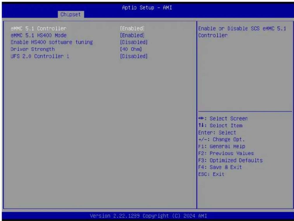
3.5.2.7 SCS Configuration
text_image
Aptio Setup - AMI Chipset eMMC 5.1 Controller [Enabled] eMMC 5.1 HS400 Mode [Enabled] Enable HS400 software tuning [Disabled] Driver Strength [40 Ohm] UFS 2.0 Controller 1 [Disabled] Enable or Disable SCS eMMC 5.1 Controller +: Select Screen ↑↓: Select Item Enter: Select +/-: Change Opt. F1: General Help F2: Previous Values F3: Optimized Defaults F4: Save & Exit ESC: Exit Version 2.22.1239 Copyright (C) 2024 AMIFigure 3.38 SCS Configuration
■ eMMC 5.1 Controller
Enable/Disable SCS eMMC 5.1 Controller.
eMMC 5.1 HS400 Mode
Enable/Disable SCS eMMC 5.1 HS400 Mode.
■ Enable HS400 software tuning
Software tuning should improve eMMC HS400 stability at the expense of boot time.
Driver Strength
Sets I/O driver strength.
■ UFS 2.0 Controller 1
Enable/Disable the UFS 2.0 Controller.
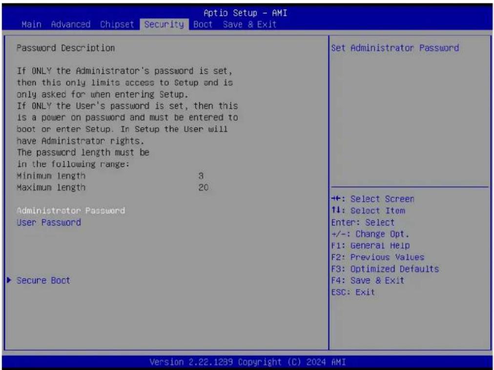
3.6 Security Chipset
text_image
Aptio Setup - AMI Main Advanced Chipset Security Boot Save & Exit Password Description If ONLY the Administrator's password is set, then this only limits access to Setup and is only asked for when entering Setup. If ONLY the User's password is set, then this is a power on password and must be entered to boot or enter Setup. In Setup the User will have Administrator rights. The password length must be in the following range: Minimum length 3 Maximum length 20. Administrator Password User Password ► Secure Boot Set Administrator Password +: Select Screen ↑↓: Select Item Enter: Select +/-: Change Opt. F1: General Help F2: Previous Values F3: Optimized Defaults F4: Save & Exit ESC: Exit Version 2.22.1239 Copyright (C) 2024 AMIFigure 3.39 Security Chipset
Administrator Password
Set the Setup Administrator Password.
User Password
Set the User Password.
Secure Boot
Secure Boot Configuration.
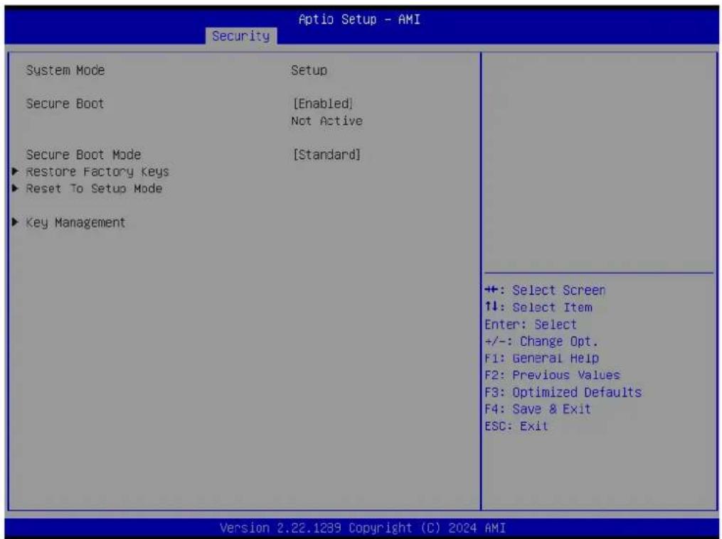
3.6.1 Secure Boot
text_image
Aptio Setup - AMI Security System Mode Setup Secure Boot [Enabled] Not Active Secure Boot Mode [Standard] ►Restore Factory Keys ►Reset To Setup Mode ►Key Management ++: Select Screen ↑↓: Select Item Enter: Select +/-: Change Opt. F1: General Help F2: Previous Values F3: Optimized Defaults F4: Save & Exit ESC: Exit Version 2.22.1239 Copyright (C) 2024 AMIFigure 3.40 Secure Boot
Secure Boot
The Secure Boot feature is Active if Secure Boot is Enabled; Platform Key(PK) is enrolled and the System is in User mode. The mode change requires a platform reset.
- Secure Boot Mode
Secure Boot mode options:
Standard or Custom.
In Custom mode, Secure Boot Policy variables can be configured by a physically present user without full authentication.
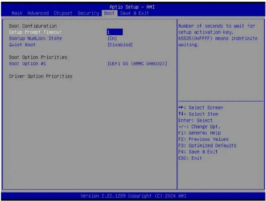
3.7 Boot Setup
text_image
Aptio Setup - AMI Main Advanced Chipset Security Boot Save & Exit Boot Configuration Setup Prompt Timeout Bootup NumLock State Quiet Boot 1 [On] [Disabled] Boot Option Priorities Boot Option #1 [UEFI OS (EMMC DA6032)] Driver Option Priorities Number of seconds to wait for setup activation key. 65535(0xFFFF) means indefinite waiting. +: Select Screen 1: Select Item Enter: Select +/-: Change Opt. F1: General Help F2: Previous Values F3: Optimized Defaults F4: Save & Exit ESC: Exit Version 2.22.1239 Copyright (C) 2024 AMIFigure 3.41 Boot Setup
Setup Prompt Timeout
Number of seconds to wait for the setup activation key. 65535(0xFFFF) means indefinite waiting.
■ Bootup NumLock State
Select the keyboard NumLock state.
Quiet Boot
Enable/Disable the Quiet Boot option.
■ Boot Option #1
Sets the system boot order.
3.8 Save & Exit

text_image
Aptio Setup - AMI Main Advanced Chipset Security Boot Save & Exit Save Options Save Changes and Exit Discard Changes and Exit Save Changes and Reset Discard Changes and Reset Save Changes Discard Changes Default Options Restore Defaults Save as User Defaults Restore User Defaults Boot Override UEFI OS (eMMC DA6032) Exit system setup after saying the changes. ++: Select Screen ↑↓: Select Item Enter: Select +/-: Change Opt. F1: General Help F2: Previous Values F3: Optimized Defaults F4: Save & Exit ESC: Exit Version 2.22.1239 Copyright (C) 2024 AMIFigure 3.42 Save & Exit
■ Save Changes and Exit
Exit system setup after saving the changes.
■ Discard Changes and Exit
Exit system setup without saving any changes.
■ Save Changes and Reset
Reset the system after saving the changes.
■ Discard Changes and Reset
Reset system setup without saving any changes.
■ Save Changes
Save changes done so far to any of the setup options.
■ Discard Changes
Discard changes done so far to any of the setup options.
Restore Defaults
Restore/Load default values for all the setup options.
■ Save as User Defaults
Save the changes done so far as user defaults.
Restore User Defaults
Restore the user defaults to all the setup options.
Boot Override
Chapter 4
S/W Introduction & Installation
S/W Introduction
Driver Installation
■ Advantech iManager
4.1 S/W Introduction
The mission of Advantech Embedded Software Services is to "Enhance quality of life with Advantech platforms and Microsoft Windows embedded technology." We enable Windows Embedded software products on Advantech platforms to more effectively support the embedded computing community. Customers are freed from the hassle of dealing with multiple vendors (Hardware suppliers, System integrators, Embedded OS distributor) for projects. Our goal is to make Windows Embedded Software solutions easily and widely available to the embedded computing community.
4.2 Driver Installation
The Intel® Chipset Software Installation (CSI) utility installs the Windows INF files that outline to the operating system how the chipset components will be configured.
4.2.1 Windows Driver Setup
To install the drivers on a Windows-based operation system, please connect to the Internet and browse the website http://support.advantech.com.tw and download the installation drivers and follow the Driver Setup instructions to complete the installation.
4.2.2 Other OS
Linux Ubuntu
4.3 Advantech iManager
Advantech's platforms come equipped with iManager, a micro-controller that provides embedded features for system integrators. Embedded features have been moved from the OS/BIOS level to the board level to increase reliability and simplify integration. iManager runs whether the operating system is running or not; it can count the boot times and running hours of the device, monitor device health, and provide an advanced watchdog to handle errors just as they happen. iManager also comes with a secure & encrypted EEPROM for storing important security keys or other customer-defined information. All the embedded functions are configured through the API and provide corresponding utilities to demonstrate. These APIs comply with PICMG EAPI (Embedded Application Programmable Interface) specifications and unify in the same structures. It makes these embedded features easier to integrate, speeds up development schedules, and provides the customer with software continuity when upgrading hardware. For more details on how to use the APIs and utilities, please refer to the Advantech iManager 2.0 Software API User Manual.
Control

GPIO
General Purpose Input/Output is a flexible parallel interface that allows a variety of custom connections. It allows users to monitor the level of signal input or set the output status to switch on/off a device. Our API also provides Programmable GPIO, which allows developers to dynamically set the GPIO input or output status.

SMBus
SMBus is the System Management Bus defined by Intel® Corporation in 1995. It is used in personal computers and servers for low-speed system management communications. The SMBus API allows a developer to interface a embedded system environment and transfer serial messages using the SMBus protocols, allowing multiple simultaneous device control.

PC
^1 PC is a bi-directional two wire bus that was developed by Phillips for use in their televisions in the 1980s. The ^2 PC API allows a developer to interface with an embedded system environment and transfer serial messages using the ^3 PC protocols, allowing multiple simultaneous device control.
Display

Brightness Control
The Brightness Control API allows a developer to interface with an embedded device to easily control brightness.

Backlight
The Backlight API allows a developer to control the backlight (screen) on/off in an embedded device.
Monitor

Watchdog
A watchdog timer (WDT) is a device that performs a specific operation after a certain period of time if something goes wrong and the system does not recover on its own. A watchdog timer can be programmed to perform a warm boot (restarting the system) after a certain number of seconds.

Hardware Monitor
The Hardware Monitor (HWM) API is a system health supervision API that inspects certain condition indexes, such as fan speed, temperature and voltage.

Hardware Control
The Hardware Control API allows developers to set the PWM (Pulse Width Modulation) value to adjust fan speed or other devices; it can also be used to adjust the LCD brightness.
Power Saving

CPU Speed
Make use of Intel SpeedStep technology to reduce power power consumption. The system will automatically adjust the CPU Speed depending on system loading.

System Throttling
Refers to a series of methods for reducing power consumption in computers by lowering the clock frequency. These APIs allow the user to lower the clock from 87.5% to 12.5%.
Appendix A
Pin Assignments
This appendix gives you information about hardware pin assignments for the SOM-2533 CPU System on Module.
Sections include:
■ SOM-2533 Pin Assignments
A.1 SOM-2533 Pin Assignments
This section gives SOM-2533 pin assignments for the SMARC connector which is compliant with SMARC 2.1.1 definitions. More details about how to use these pins is available for design reference. Please contact Advantech for a design guide, checklist, reference schematic, and other hardware/software support.
Table A.1: SOM-2533 Pin Assignments
SMARC Function Pin Pin Name SOM-2533
| LVDS/eDP | S125 LVDS0_0+ / eDP0_TX0+ /DSI0_D0+ v /v/- | |
| S126 LVDS0_0- / eDP0_TX0- /DSI0_D0- v /v/- | ||
| S128 LVDS0_1+ / eDP0_TX1+ /DSI0_D1+ v /v/- | ||
| S129 LVDS0_1- / eDP0_TX1- /DSI0_D1- v /v/- | ||
| S131 LVDS0_2+ / eDP0_TX2+ /DSI0_D2+ v /v/- | ||
| S132 LVDS0_2- / eDP0_TX2- /DSI0_D2- v /v/- | ||
| S137 LVDS0_3+ / eDP0_TX3+ /DSI0_D3+ v /v/- | ||
| S138 LVDS0_3- / eDP0_TX3- /DSI0_D3- v /v/- | ||
| S134 LVDS0_CK+ / eDP0_AUX+ /DSI0_CLK+ v /v/- | ||
| S135 LVDS0_CK- / eDP0_AUX- /DSI0_CLK- v /v/- | ||
| S111 LVDS1_0+ / eDP1_TX0+ /DSI1_D0+ v / -/- | ||
| S112 LVDS1_0- / eDP1_TX0- /DSI1_D0- v / -/- | ||
| S114 LVDS1_1+ / eDP1_TX1+ /DSI1_D1+ v / -/- | ||
| S115 LVDS1_1- / eDP1_TX1- /DSI1_D1- v / -/- | ||
| S117 LVDS1_2+ / eDP1_TX2+ /DSI1_D2+ v / -/- | ||
| S118 LVDS1_2- / eDP1_TX2- /DSI1_D2- v / -/- | ||
| S120 LVDS1_3+ / eDP1_TX3+ /DSI1_D3+ v / -/- | ||
| S121 LVDS1_3- / eDP1_TX3- /DSI1_D3- v / -/- | ||
| S108 LVDS1_CK+ / eDP1_AUX+ /DSI1_CLK+ v / -/- | ||
| S109 LVDS1_CK- / eDP1_AUX- /DSI1_CLK- v / -/- | ||
| S139 I2C_LCD_CK v | ||
| S140 I2C_LCD_DAT v | ||
| S133 LCD0_VDD_EN v | ||
| S116 LCD1_VDD_EN v | ||
| S127 LCD0_BKLT_EN v | ||
| S107 LCD1_BKLT_EN v | ||
| S141 LCD0_BKLT_PWM v | ||
| S122 LCD1_BKLT_PWM v | ||
| S144 EDP0_HPD / DSIO_TE v/- | ||
| S113 EDP1_HPD - | ||
| DP++ over HDMI | P92 DP1_LANEO+ / HDMI_D2+ v/v | |
| P93 DP1_LANEO- / HDMI_D2- v/v | ||
| P95 DP1_LANE1+ / HDMI_D1+ v/v | ||
| P96 DP1_LANE1- / HDMI_D1- v/v | ||
| P98 DP1_LANE2+ / HDMI_D0+ v/v | ||
| P99 DP1_LANE2- / HDMI_D0- v/v | ||
| P101 DP1_LANE3+ / HDMI_CK+ v/v | ||
| P102 DP1_LANE3- / HDMI_CK- v/v | ||
| P104 DP1_HPD / HDMI_HPD v/v | ||
Table A.1: SOM-2533 Pin Assignments
| DP++ over HDMI | P105 DP1_AUX- / HDMI_CTRL_DAT v/v |
| P106 DP1_AUX+ / HDMI_CTRL_CK v/v | |
| P107 DP1_AUX_SEL v | |
| DP++ | S102 DP0_LANE3+ v |
| S103 DP0_LANE3- v | |
| S99 DP0_LANE2+ v | |
| S100 DP0_LANE2- v | |
| S96 DP0_LANE1+ v | |
| S97 DP0_LANE1- v | |
| S93 DP0_LANE0+ v | |
| S94 DP0_LANE0- v | |
| S105 DP0_AUX+ v | |
| S106 DP0_AUX - v | |
| S98 DP0_HPD v | |
| S95 DP0_AUX_SEL v | |
| CSI | P108 GPIO0 / CAM0_PWR# v/- |
| P109 GPIO1 / CAM1_PWR# v/- | |
| P110 GPIO2 / CAM0_RST# v/- | |
| P111 GPIO3 / CAM1_RST# v/- | |
| S7 I2C_CAM0_DAT - | |
| S5 I2C_CAM0_CK - | |
| S2 I2C_CAM1_DAT - | |
| S1 I2C_CAM1_CK - | |
| S11 CSIO_RX0+ - | |
| S12 CSIO_RX0- - | |
| S14 CSIO_RX1+ - | |
| S15 CSIO_RX1- - | |
| P7 CSI1_RX0+ - | |
| P8 CSI1_RX0- - | |
| P10 CSI1_RX1+ - | |
| P11 CSI1_RX1- - | |
| P13 CSI1_RX2+ - | |
| P14 CSI1_RX2- - | |
| P16 CSI1_RX3+ - | |
| P17 CSI1_RX3- - | |
| S8 CSIO_CK+ - | |
| S9 CSIO_CK- - | |
| P3 CSI1_CK+ - | |
| P4 CSI1_CK- - | |
| S6 CAM_MCK - | |
| SDIO Card | P39 SDIO_D0 - |
| P40 SDIO_D1 - | |
| P41 SDIO_D2 - | |
| P42 SDIO_D3 - | |
| P33 SDIO_CMD - | |
| P36 SDIO_CK - | |
| P34 SDIO_WP - |
Table A.1: SOM-2533 Pin Assignments
| SDIO Card | P35 SDIO_CD# - | |
| P37 SDIO_PWR_EN - | ||
| SPI0 | P43 SPI0_CS0# v | |
| P31 SPI0_CS1# v | ||
| P44 SPI0_CK v | ||
| P45 SPI0_DIN v | ||
| P46 SPI0_DO v | ||
| eSPI/SPI1 | P56 ESPI_CK / SPI1_CK / QSPI_CK v / v/- | |
| P54 ESPI_CS0# / SPI1_CS0# / QSPI_CS0# v / v/- | ||
| P55 ESPI_CS1# / SPI1_CS1# / QSPI_CS1# - / -/- | ||
| P57 ESPI_IO_1 / SPI1_DIN / QSPI_IO_1 v / v/- | ||
| P58 ESPI_IO_0 / SPI1_DO /QSPI_IO_0 v / v/- | ||
| S56 ESPI_IO_2 / QSPI_IO_2 v / - | ||
| S57 ESPI_IO_3 / QSPI_IO_3 v / - | ||
| S58 ESPI_RESET# v | ||
| S43 ESPI_ALERT0# v | ||
| S44 ESPI_ALERT1# - | ||
| I2S | S39 I2S0_LRCK v | |
| S40 I2S0_SDOUT | v | |
| S41 I2S0_SDIN v | ||
| S42 I2S0_CK | v | |
| S38 AUDIO_MCK | v | |
| HDA / I2S | S50 HDA_SYNC / I2S2_LRCK | v / - |
| S51 HDA_SDO / I2S2_SDOUT | v / - | |
| S52 HDA_SDI / I2S2_SDIN | v / - | |
| S53 HDA_CK / I2S2_CK | v / - | |
| P112 HDA_RST# v | ||
| I2C Interfaces | S48 I2C_GP_CK v | |
| S49 I2C_GP_DAT | v | |
| Serial Ports | P129 SER0_TX | v |
| P130 SER0_RX | v | |
| P134 SER1_TX v | ||
| P135 SER1_RX | v | |
| P136 SER2_TX v | ||
| P137 SER2_RX | v | |
| P140 SER3_TX v | ||
| P141 SER3_RX | v | |
| P131 SER0_RTS# | v | |
| P132 SER0_CTS# | v | |
| P138 SER2_RTS# | - | |
| P139 SER2_CTS# | - | |
| CAN Bus | P143 CAN0_TX | v |
| P145 CAN1_TX | v | |
| P144 CAN0_RX | v | |
| P146 CAN1_RX | v | |
Table A.1: SOM-2533 Pin Assignments
| USB | P60 USB0+ v | |
| P61 USB0- v | ||
| P65 USB1+ v | ||
| P66 USB1- v | ||
| P69 USB2+ v | ||
| P70 USB2- v | ||
| S68 USB3+ v | ||
| S69 USB3- v | ||
| S35 USB4+ v | ||
| S36 USB4- v | ||
| S59 USB5+ v | ||
| S60 USB5- v | ||
| P62 USB0_EN_OC# v | ||
| P67 USB1_EN_OC# v | ||
| P71 USB2_EN_OC# v | ||
| P74 USB3_EN_OC# v | ||
| P76 USB4_EN_OC# v | ||
| S55 USB5_EN_OC# v | ||
| P63 USB0_VBUS_DET - | ||
| S37 USB3_VBUS_DET - | ||
| P64 USB0_OTG_ID - | ||
| S104 USB3_OTG_ID - | ||
| S75 USB2SSRX- v | ||
| S74 USB2SSRX+ v | ||
| S66 USB3SSRX- v | ||
| S65 USB3SSRX+ v | ||
| S72 USB2SSTX- v | ||
| S71 USB2SSTX+ v | ||
| S63 USB3SSTX- v | ||
| S62 USB3SSTX+ v | ||
| PCIe | P89 PCIE_A_TX+ v | |
| P90 PCIE_A_TX- v | ||
| S90 PCIE_B_TX+ v | ||
| S91 PCIE_B_TX- v | ||
| S81 PCIE_C_TX+ / SERDES_1_TX+ | v/- | |
| S82 PCIE_C_TX- / SERDES_1_TX- | v/- | |
| S29 PCIE_D_TX+ / SERDES_0_TX+ | v/v | |
| S30 PCIE_D_TX- / SERDES_0_TX- | v/v | |
| P86 PCIE_A_RX+ | v | |
| P87 PCIE_A_RX- | v | |
| S87 PCIE_B_RX+ | v | |
| S88 PCIE_B_RX- | v | |
| S78 PCIE_C_RX+ / SERDES_1_RX+ | v/- | |
| S79 PCIE_C_RX- / SERDES_1_RX | v/- | |
| S32 PCIE_D_RX+ / SERDES_0_RX+ | v/v | |
| S33 PCIE_D_RX- / SERDES_0_RX- | v/v | |
| P83 PCIE_A_REFCK+ | v |
Table A.1: SOM-2533 Pin Assignments
| PCIe | P84 PCIE_A_REFCK- v | |
| S84 PCIE_B_REFCK+ v | ||
| S85 PCIE_B_REFCK- v | ||
| P80 PCIE_C_REFCK+ v | ||
| P81 PCIE_C_REFCK- v | ||
| P75 PCIE_A_RST# v | ||
| S76 PCIE_B_RST# v | ||
| S77 PCIE_C_RST# v | ||
| S146 PCIE_WAKE# v | ||
| SATA | P48 SATA_TX+ v | |
| P49 SATA_TX- v | ||
| P51 SATA_RX+ v | ||
| P52 SATA_RX- | v | |
| S54 SATA_ACT# | v | |
| Ethernet | P30 GBE0_MDI0+ | v |
| P29 GBE0_MDI0- | v | |
| P27 GBE0_MDI1+ | v | |
| P26 GBE0_MDI1- | v | |
| P24 GBE0_MDI2+ | v | |
| P23 GBE0_MDI2- | v | |
| P20 GBE0_MDI3+ | v | |
| P19 GBE0_MDI3- | v | |
| S17 GBE1_MDI0+ | v | |
| S18 GBE1_MDI0- | v | |
| S20 GBE1_MDI1+ | v | |
| S21 GBE1_MDI1- | v | |
| S23 GBE1_MDI2+ | v | |
| S24 GBE1_MDI2- | v | |
| S26 GBE1_MDI3+ | v | |
| S27 GBE1_MDI3- | v | |
| P21 GBE0_LINK100# | v | |
| S19 GBE0_LINK100# | v | |
| P22 GBE0_LINK1000# | v | |
| S22 GBE1_LINK1000# | v | |
| P25 GBE0_LINK_ACT# | v | |
| s31 GBE1_LINK_ACT# | v | |
| P28 GBE0_CTREF | - | |
| S28 GBE1_CTREF | - | |
| P6 GBE0_SDP v | ||
| P5 GBE1_SDP v | ||
| Watchdog | S145 WDT_TIME_OUT# | v |
Table A.1: SOM-2533 Pin Assignments
| GPIO | P108 GPIO0 / CAM0_PWR# v/ - | |
| P109 GPIO1 / CAM1_PWR# v/ - | ||
| P110 GPIO2 / CAM0_RST# v/ - | ||
| P111 GPIO3 / CAM1_RST# v/ - | ||
| P112 GPIO4 / HDA_RST# v/ v | ||
| P113 GPIO5 / PWM_OUT v/ v | ||
| P114 GPIO6 / TACHIN v/ v | ||
| P115 GPIO7 v | ||
| P116 GPIO8 v | ||
| P117 GPIO9 v | ||
| P118 GPIO10 v | ||
| P119 GPIO11 v | ||
| S142 GPIO12 v | ||
| S123 GPIO13 v | ||
| Management Pins | S150 VIN_PWR_BAD# | v |
| S154 CARRIER_PWR_ON | v | |
| S153 CARRIER_STBY# | v | |
| P126 RESET_OUT# | v | |
| P127 RESET_IN# | v | |
| P128 POWER_BTN# | v | |
| S149 SLEEP# | v | |
| S148 LID# | v | |
| S156 BATLOW# | v | |
| P122 I2C_PM_DAT | v | |
| P121 I2C_PM_CK | v | |
| S151 CHARGING# | v | |
| S152 CHARGER_PRSNT# | v | |
| S157 TEST# | v | |
| P1 SMB_ALERT | v | |
| Boot Select | P123 BOOT_SEL0# | - |
| P124 BOOT_SEL0# | - | |
| P125 BOOT_SEL2# | v | |
| S155 FORCE_RECOV# | v | |
| Power/GND/RSVD | S147 VDD_RTC | v |
| P147 VDD_IN | v | |
| P148 VDD_IN | v | |
| P149 VDD_IN | v | |
| P150 VDD_IN | v | |
| P151 VDD_IN | v | |
| P152 VDD_IN | v | |
| P153 VDD_IN | v | |
| P154 VDD_IN | v | |
| P155 VDD_IN | v | |
| P156 VDD_IN | v | |
| P2 GND | v | |
| P9 GND | v | |
| P12 GND | v | |
Table A.1: SOM-2533 Pin Assignments
| P12 GND v | |
| P15 GND v | |
| P18 GND v | |
| P32 GND v | |
| P38 GND v | |
| P47 GND v | |
| P50 GND v | |
| P53 GND v | |
| P59 GND v | |
| P68 GND v | |
| P79 GND v | |
| P82 GND v | |
| P85 GND v | |
| P88 GND v | |
| P91 GND v | |
| P94 GND v | |
| P97 GND v | |
| P100 GND v | |
| P103 GND v | |
| P120 GND v | |
| P133 GND v | |
| P142 GND v | |
| S3 GND v | |
| Power/GND/RSVD | S10 GND v |
| S13 GND v | |
| S16 GND v | |
| S25 GND v | |
| S34 GND v | |
| S47 GND v | |
| S61 GND v | |
| S64 GND v | |
| S67 GND v | |
| S70 GND v | |
| S73 GND v | |
| S80 GND v | |
| S83 GND v | |
| S86 GND v | |
| S89 GND v | |
| S92 GND v | |
| S101 GND v | |
| S110 GND v | |
| S119 GND v | |
| S124 GND v | |
| S130 GND v | |
| S136 GND v | |
| S143 GND v | |
| P72 RSVD NC |
Table A.1: SOM-2533 Pin Assignments
| Power/GND/RSVD | P73 RSVD NC |
| P77 RSVD NC | |
| P78 RSVD NC | |
| S4 RSVD NC | |
| S45 RSVD NC | |
| S46 RSVD NC | |
| S123 RSVD NC | |
| S142 RSVD NC | |
| S158 RSVD NC | |
| JTAG | - VDD_JTAG_IO NC |
| - JTAG_TRST# NC | |
| - JTAG_TMS NC | |
| - JTAG_TDO NC | |
| - JTAG_TDI NC | |
| - JTAG_TCK NC |
Appendix B
Watchdog Timer
This appendix gives you information about programming the watchdog timer on the SOM-2533 CPU System on Module.
Sections include:
■ Watchdog Timer Programming
B.1 Programming the Watchdog Timer
Table B.1: Programming the Watchdog Timer
| Trigger Event Note |
| IRQ (BIOS setting default disable)** |
| NMI N/A |
| SCI Power button event |
| Power Off Support |
| H/W Restart Support |
| WDT Pin Activate Support |
** WDT new driver support automatically selects an available IRQ number from the BIOS, and then sets it to EC. Only Win10 supports it.
In other OS, it will still use the IRQ number from the BIOS setting as usual.
For details, please refer to the iManager & Software API User Manual.
Appendix
C
System Assignments
This appendix gives you information about system resource allocation on the SOM-2533 CPU System on Module.
Sections include:
System I/O Ports
■ DMA Channel Assignments
■ Interrupt Assignments
■ ^st MB Memory Map
C.1 System I/O Ports
Table C.1: System I/O Ports
| Resource Device |
| 0x00000000-0x00000CF7 PCI Express Root Complex |
| 0x00000020-0x00000021 Programmable interrupt controller |
| 0x00000024-0x00000025 Programmable interrupt controller |
| 0x00000028-0x00000029 Programmable interrupt controller |
| 0x0000002C-0x0000002D Programmable interrupt controller |
| 0x0000002E-0x0000002F Motherboard resources |
| 0x00000030-0x00000031 Programmable interrupt controller |
| 0x00000034-0x00000035 Programmable interrupt controller |
| 0x00000038-0x00000039 Programmable interrupt controller |
| 0x0000003C-0x0000003D Programmable interrupt controller |
| 0x00000040-0x00000043 System timer |
| 0x0000004E-0x0000004F Motherboard resources |
| 0x00000050-0x00000053 System timer |
| 0x00000061-0x00000061 Motherboard resources |
| 0x00000062-0x00000062 Microsoft ACPI-Compliant Embedded Controller |
| 0x00000063-0x00000063 Motherboard resources |
| 0x00000065-0x00000065 Motherboard resources |
| 0x00000066-0x00000066 Microsoft ACPI-Compliant Embedded Controller |
| 0x00000067-0x00000067 Motherboard resources |
| 0x00000070-0x00000070 Motherboard resources |
| 0x00000080-0x00000080 Motherboard resources |
| 0x00000092-0x00000092 Motherboard resources |
| 0x000000A0-0x000000A1 Programmable interrupt controller |
| 0x000000A4-0x000000A5 Programmable interrupt controller |
| 0x000000A8-0x000000A9 Programmable interrupt controller |
| 0x000000AC-0x000000AD Programmable interrupt controller |
| 0x000000B0-0x000000B1 Programmable interrupt controller |
| 0x000000B2-0x000000B3 Motherboard resources |
| 0x000000B4-0x000000B5 Programmable interrupt controller |
| 0x000000B8-0x000000B9 Programmable interrupt controller |
| 0x000000BC-0x000000BD Programmable interrupt controller |
| 0x0000029C-0x0000029D Motherboard resources |
| 0x000002F8-0x000002FF Communications Port (COM2) |
| 0x000003F8-0x000003FF Communications Port (COM1) |
| 0x000004D0-0x000004D1 Programmable interrupt controller |
| 0x00000680-0x0000069F Motherboard resources |
| 0x00000D00-0x0000FFFF PCI Express Root Complex |
| 0x0000164E-0x0000164F Motherboard resources |
| 0x00001854-0x00001857 Motherboard resources |
| 0x00002000-0x000020FE Motherboard resources |
| 0x00003000-0x0000303F Intel® UHD Graphics |
| 0x00003060-0x0000307F Standard SATA AHCI Controller |
| 0x00003080-0x00003083 Standard SATA AHCI Controller |
| 0x00003090-0x00003097 Standard SATA AHCI Controller |
C.2 Interrupt Assignments
Table C.2: Interrupt Assignments
| Resource Device | |
| IRQ 0 System timer | |
| IRQ 3 Communications Port (COM2) | |
| IRQ 7 Communications Port (COM1) | |
| IRQ 14 Intel® Serial IO GPIO Host Controller - INTC1057 | |
| IRQ 16 Communications Port (COM3) | |
| IRQ 16 Intel SD Host Controller | |
| IRQ 17 USB Synopsys Controller | |
| IRQ 27 Intel® Serial IO I2C Host Controller - 54E8 | |
| IRQ 29 Intel® Serial IO I2C Host Controller - 54EA | |
| IRQ 31 Intel® Serial IO I2C Host Controller - 54C5 | |
| IRQ 42 Communications Port (COM4) | |
| IRQ 55-204 Microsoft ACPI-Compliant System | |
| IRQ 256-511 Microsoft ACPI-Compliant System | |
| IRQ 4294967269 Intel® Management Engine Interface #1 | |
| IRQ 4294967270 Intel® Smart Sound Technology BUS | |
| IRQ 4294967271-4294967279 | Intel® Ethernet Controller I226-LM #2 |
| IRQ 4294967280-4294967288 | Intel® Ethernet Controller I226-LM |
| IRQ 4294967289 Intel® USB 3.10 eXtensible Host Controller - 1.20 (Microsoft) | |
| IRQ 4294967290 Intel® UHD Graphics | |
| IRQ 4294967291 Standard SATA AHCI Controller | |
| IRQ 4294967292 PCI Express Root Port #1 - 54B8 | |
| IRQ 4294967293 PCI Express Root Port #4 - 54BB | |
| IRQ 4294967294 PCI Express Root Port #3 - 54BA | |
C.3 1st MB Memory Map
Table C.3: 1st MB Memory Map
| Resource Device | |
| 0x0000-0xFFFFF Intel® UHD Graphics | |
| 0x0000-0xFFFFF Intel® UHD Graphics | |
| 0x1300000-0x130FFFF Intel® USB 3.10 eXtensible Host Controller - 1.20 (Microsoft) | |
| 0x1310000-0x1317FFF Performance Monitor | |
| 0x1329000-0x1329FFF Intel® SD Host Controller | |
| 0x80400000-0x806FFFFF PCI Express Root Port #4 - 54BB | |
| 0x80400000-0x806FFFFF PCI Express Root Complex | |
| 0x80500000-0x805FFFFF Intel® Ethernet Controller I226-LM | |
| 0x80600000-0x80603FFF Intel® Ethernet Controller I226-LM | |
| 0x80700000-0x809FFFFF PCI Express Root Port #3 - 54BA | |
| 0x80800000-0x808FFFFF Intel® Ethernet Controller I226-LM #2 | |
| 0x80900000-0x80903FFF Intel® Ethernet Controller I226-LM #2 | |
| 0x80A00000-0x80A01FFF Standard SATA AHCI Controller | |
| 0x80A02000-0x80A027FF Standard SATA AHCI Controller | |
| 0x80A03000-0x80A030FF Standard SATA AHCI Controller | |
| 0xA0000-0xBFFFF PCI Express Root Complex | |
| 0xC0000000-0xCFFFFFFF Motherboard resources | |
| 0xE0000-0xE3FFF PCI Express Root Complex | |
| 0xE4000-0xE7FFF PCI Express Root Complex | |
| 0xE8000-0xEBFFF PCI Express Root Complex | |
| 0xEC000-0xFFFFF PCI Express Root Complex | |
| 0xF0000-0xFFFFF PCI Express Root Complex | |
| 0xFD690000-0xFD69FFFF Intel® Serial IO GPIO Host Controller - INTC1057 | |
| 0xFD6A0000-0xFD6AFFF Intel® Serial IO GPIO Host Controller - INTC1057 | |
| 0xFD6D0000-0xFD6DFFF Intel® Serial IO GPIO Host Controller - INTC1057 | |
| 0xFD6E0000-0xFD6EFFF Intel® Serial IO GPIO Host Controller - INTC1057 | |
| 0xFE010000-0xFE010FFF SPI (flash) Controller - 54A4 | |
| 0xFE03E000-0xFE03E007 Communications Port (COM3) | |
| 0xFE03E008-0xFE03EFFF Motherboard resources | |
| 0xFE03F000-0xFE03FFF Motherboard resources | |
| 0xFE042000-0xFE042007 Communications Port (COM4) | |
| 0xFE042008-0xFE042FFF Motherboard resources | |
| 0xFE043000-0xFE043FFF Motherboard resources | |
| 0xFED00000-0xFED003FF High precision event timer | |
| 0xFED20000-0xFED7FFF Motherboard resources | |
| 0xFED40000-0xFED44FFF Trusted Platform Module 2.0 | |
| 0xFED45000-0xFED8FFF Motherboard resources | |
| 0xFED90000-0xFED93FFF Motherboard resources | |
| 0xFEDA0000-0xFEDA0FFF Motherboard resources | |
| 0xFEDA1000-0xFEDA1FFF Motherboard resources | |
| 0xFEDC0000-0xFEDC7FFF Motherboard resources | |
| 0xFEE00000-0xFEEFFFFF Motherboard resources | |
| 0xFFCF7000-0xFFCF7FFF Intel® Management Engine Interface #1 |
Table C.3: 1st MB Memory Map
| 0xFFCF8000-0xFFCF8FFF Intel® Serial IO I2C Host Controller - 54EA |
| 0xFFCF9000-0xFFCF9FFF Intel® Serial IO I2C Host Controller - 54E8 |
| 0xFFCFA000-0xFFCFAFFF USB Synopsys Controller |
| 0xFFCFB000-0xFFCFBFFF Intel® Serial IO I2C Host Controller - 54C5 |
| 0xFFCFC000-0xFFCFFFFFF Intel® Smart Sound Technology BUS |
| 0xFFD00000-0xFFDFFFFFF Intel® Smart Sound Technology BUS |
| 0xFFE00000-0xFFFFFFFF USB Synopsys Controller |
www.advantech.com
Please verify specifications before quoting. This guide is intended for reference purposes only.
All product specifications are subject to change without notice.
No part of this publication may be reproduced in any form or by any means, such as electronically, by photocopying, recording, or otherwise, without prior written permission from the publisher.
All brand and product names are trademarks or registered trademarks of their respective companies.
© Advantech Co., Ltd. 2024