PZICE - Accessory Panduit - Free user manual and instructions
Find the device manual for free PZICE Panduit in PDF.

User questions about PZICE Panduit
0 question about this device. Answer the ones you know or ask your own.
Ask a new question about this device
Download the instructions for your Accessory in PDF format for free! Find your manual PZICE - Panduit and take your electronic device back in hand. On this page are published all the documents necessary for the use of your device. PZICE by Panduit.
USER MANUAL PZICE Panduit
INSTALLATION INSTRUCTIONS CM363
(1) Set of two Keys
(1) Left Mounting Bracket
(1) Right Mounting Bracket
(6) Grommets
(2) Tak-Ty Rolls (Hook and Loop)
(1) Ceiling Tile Template
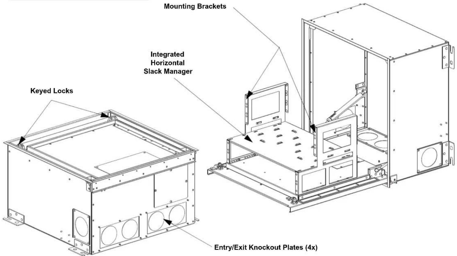
(1) Integrated Horizontal Slack Manager
(4) Entry/Exit Knockout Plates
Set of two keys
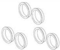
Grommets

Ceiling tile template


Tak Ties
text_image
Mounting Brackets Integrated Horizontal Slack Manager Keyed Locks Entry/Exit Knockout Plates (4x)Table of Contents
Install in Ceiling....2
Equipment Installation....3
Cable Routing and Slack 4
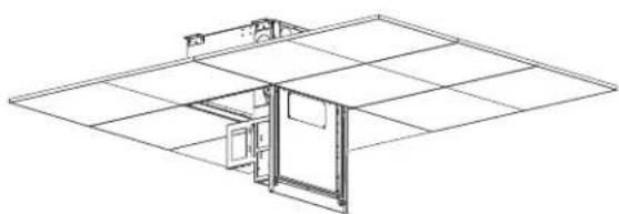
Install in Ceiling
Install (4) threaded rods to the building structure. The threaded rod must be attached on all four corners of the enclosure with a nut and washer above and below the support bracket. Level the enclosure so the weight is not supported by the ceiling grid system.

natural_image
Technical line drawing showing a mechanical assembly with mounting bracket and housing, no text or symbols presentInsert Ceiling Tile Cutout into Housing
While the enclosure is installed in the ceiling and open, remove the (3) #6-32 screws and ceiling tile bracket as shown below. Once removed, slide the ceiling tile cutout into place fitting around the fan module. After proper orientation is achieved, replace the ceiling tile bracket and the (3) #6-32 screws back into enclosure.
natural_image
Isometric line drawing of a room layout with doors and a central door (no text or symbols)Ceiling Tile Cutout
Place the included ceiling tile cutout template over the removed ceiling tile. Secure the template with tape of thumb tacks. Trace the outline with a utility knife to extract the necessary shape to insert into the enclosure.
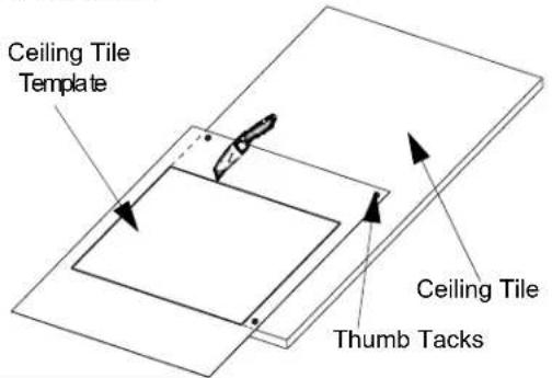
text_image
Ceiling Tile Template Ceiling Tile Thumb Tacks
text_image
#6-32 Screws Ceiling Tile Bracket Ceiling Tile CutoutNetwork Equipment Installation
Adjust the brackets forward or backward to accommodate the desired depth for the intended network equipment. Shown below are two examples of where to attach the mounting brackets, however the brackets can be adjusted in 1/2" increments to better fit desired network active equipment.
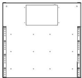
natural_image
Blank whiteboard with a small rectangular cutout and corner markers (no text or symbols)Brackets mounted toward front for deepest network equipment
natural_image
Isometric technical drawing of a mechanical assembly with two mounting brackets and a central panel (no text or symbols)
natural_image
Pure diagram of a rectangular frame with corner markers and dots, no text or symbols presentBrackets mounted toward back for shallower network equipment

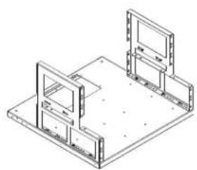
natural_image
Isometric line drawing of a mechanical assembly with two rectangular components mounted on a base plate (no text or symbols)Recommended mounting bracket location to provide the most room behind and in front of patch panels.
Mount the desired equipment to the recommended mounting locations.
Incoming horizontal cable from telecommunication room
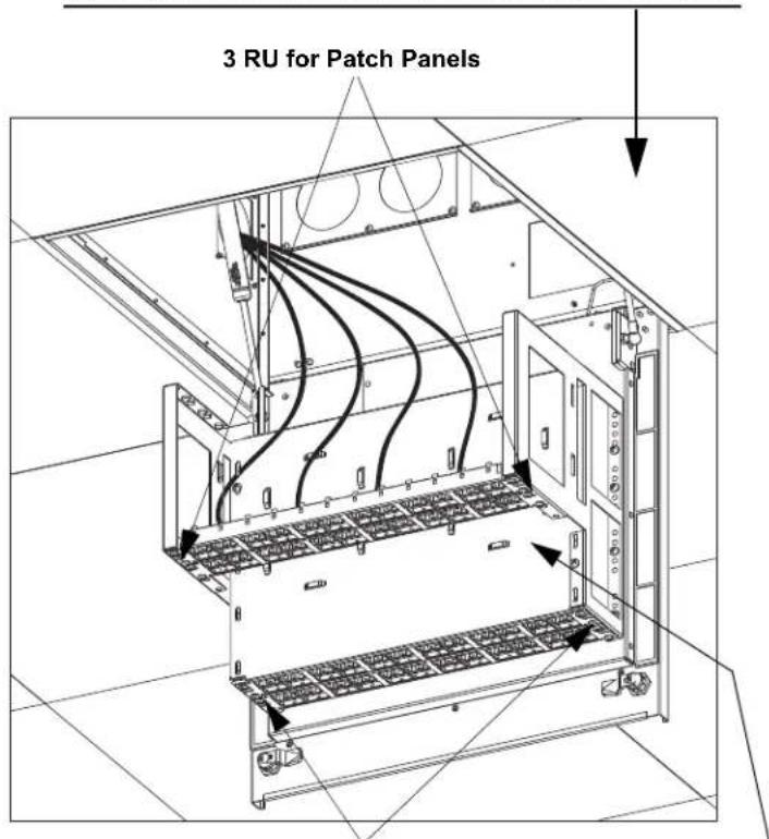
text_image
3 RU for Patch Panels2 RU for Patch Panels
Outgoing horizontal cable for work areas
natural_image
Technical line drawing of an electrical cabinet with visible wiring and mounting brackets (no text or symbols)Integrated Horizontal Slack Manager
Cable Routing and Slack Management

natural_image
Technical line drawing of a mechanical assembly with mounting brackets and wiring (no text or symbols)Entry/Exit knockouts
Determine the direction of the incoming and outgoing cables in order to select which entry/exit knockouts to remove. Once removed install the grommets from the inside of the enclosure. (Each grommet is designed to hold 48 Category 6a cables.)
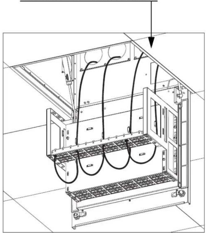
Cable Routing
Utilizing the four back grommets requires a proper slack loop to allow the door to open and close properly. The diagrams below illustrate how to route the cables and where to secure the cables using a tie-down bar. The tie off point should be approximately 24" away from cable entering point of enclosure and 6" above the top.
NOTE: Allow a minimum of 14" of cable slack to allow the door to open and close properly.
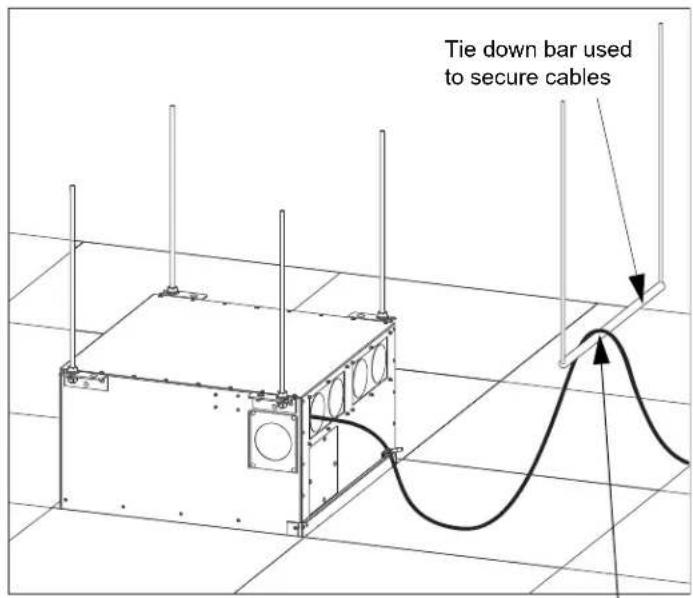
text_image
Tie down bar used to secure cablesSecure cable at this location

text_image
Enclosure door openEnclosure door closed is open bar used to secure cablesSecure' cable at this location
For instructions in Local Languages and Technical Support:
www.panduit.com/resources/install_maintain.asp

PANDUIT
www.panduit.com
E-mail:
cs@panduit.com
Fax:
(708)444-6448