
FSDP912Y - Computer Cable Panduit - Free user manual and instructions
Find the device manual for free FSDP912Y Panduit in PDF.


| Product Type | Fiber Optic Patch Cable |
| Brand | Panduit |
| Model | FSDP912Y |
| Connector Type | LC Duplex |
| Cable Type | Single-mode (OS2) |
| Length | 3 m (9.8 ft) |
| Fiber Count | 2 (duplex) |
| Insertion Loss | ≤0.3 dB |
| Return Loss | ≥55 dB |
| Operating Temperature | -20°C to +70°C |
| Storage Temperature | -40°C to +85°C |
| Cable Jacket Material | LSZH (Low Smoke Zero Halogen) |
| Cable Diameter | 3.0 mm |
| Minimum Bend Radius | 20 mm (dynamic) |
| Weight | Approx. 0.1 kg |
| Compliance | IEC 61754, TIA/EIA 568 |
| Maintenance | Clean connectors with lint-free wipes and isopropyl alcohol |
| Safety | Laser safety: avoid direct eye exposure when connected to active equipment |
| Spare Parts | Not applicable (integrated cable assembly) |
| General Information | Designed for high-speed data transmission in data center and enterprise networks |
Frequently Asked Questions - FSDP912Y Panduit
User questions about FSDP912Y Panduit
0 question about this device. Answer the ones you know or ask your own.
Ask a new question about this device
Download the instructions for your Computer Cable in PDF format for free! Find your manual FSDP912Y - Panduit and take your electronic device back in hand. On this page are published all the documents necessary for the use of your device. FSDP912Y by Panduit.
USER MANUAL FSDP912Y Panduit
natural_image
Line drawing of four types of electrical cables with exposed and hidden wires (no text or symbols)Table of Contents
2.0 Preparation Notes Tools and Material – Tools and Materials .... 3
3.0 Pulling Procedure 3
4.0 Interconnect Cable Preparation 7
4.1 Duplex Cable Preparation....7
4.2 Simplex Cable Preparation 9
5.0 Distribution Cable (≤ 24 fibers) Preparation.... 10
5.1 Jacket Preparation.... 10
6.0 Distribution Cable (>24 fibers) Preparation.... 12
6.1 Jacket Preparation.... 12
6.2 Unit Preparation.... 15
7.0 Fiber Preparation....17
DISCLAIMER OF WARRANTIES AND LIMITATION OF LIABILITIES
The practices contained herein are designed as a guide for use by persons having technical skill at their own discretion and risk. The recommended practices are based on average conditions. Panduit does not guarantee any favorable results or assume any liability in connection with this document.
In addition, the materials and hardware referenced herein appear as examples, but in no way reflect the only tools and materials available to perform these installations.
Local, State, Federal and Industry Codes and Regulations, as well as manufacturers requirements, must be consulted before proceeding with any project. Panduit makes no representations of, nor assumes any responsibility for, the accuracy or completeness of this document. Panduit disclaims any liability arising from any information contained herein or for the absence of same.
1.0 General Information
This instruction manual is a step-by-step guide for end and termination of tight-buffered cable, including sheath removal, core preparation, and fiber preparation. Local company practices and specifications may be in place concerning cable access and how it relates to a specific product or application. Modifications that do not exceed the cable's optical and mechanical performance specifications may be made to accommodate local company practices and specifications. These modifications should be made at the discretion of local company users.
Step-by-step illustrations have been provided for your reference and orientation as you follow the procedures.
2.0 Preparation Notes
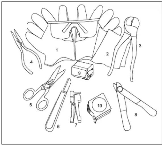
Gather the tools and materials to be used for the job and make sure they are approved by your company for use in the field and are in good working order.
Record for future reference the cable identification markings, which consist of sheath number, footage, and cable description codes printed on the cable outer sheath.
3.0 Pulling Procedure
Tools and Materials
- Eye and Hand Protection
- Linesmen Pliers
- Tight Buffer Stripping Tool
- Wire Stripping Tool
- Scissors/Snips
- Sheath Knife
- Scissors/Snips
- Needle Nose Pliers
Issue 1 October 2, 2009
700 Industrial Drive
Pulling Procedure: Installing a Wire Mesh Pulling Grip on Multifiber Tight-Buffered Fiber Optic Cables

natural_image
Illustration of a twisted rope or cable with a loop handle (no text or symbols)1. General
1.1 This procedure provides instructions for installing a wire mesh pulling grip on Panduit multifiber tight buffered fiber optic cables that are not connectorized. Examples of such cables include:
- Tight Buffered cables
- Unitized cables
- Breakout cables
1.2 Refer to the appropriate cable specification sheet or Catalog for the maximum tensile load rating of the cable to be installed.
1.3 This issue includes grip installation on cables with interlocking armor.
2. Precautions
2.1 General Precautions

Safety Glasses
WARNING: The wearing of safety glasses to protect the eyes from accidental injury is strongly recommended when handling chemicals and cutting fiber. Pieces of glass fiber are very sharp and can damage the cornea of the eye easily.
2.2 Cable Handling Precaution

Caution: Fiber optic cable is sensitive to excessive pulling, bending and crushing forces. Consult the cable specification sheet for the cable you are installing. Do not bend cable more sharply than the minimum recommended bend radius. DO not apply more pulling force to the cable than specified. Do not crush the cable or allow it to kink. Doing so may cause damage that can alter the transmission characteristics of the cable – the cable may have to be replaced.
3. Tools and Materials
3.1 The following tools and materials are required to complete this procedure:
- Kellems® pulling grip
• Side cutters (diagonal cutting pliers) - Measuring tape
• Utility knife with hook blade or cable knife
• Vinyl tape, 34 in. (19.1mm)
• Friction tape, 34 in. (19.1mm) - Gloves
- Scissors
• Swivel, ball bearing type
• Hex wrench or screwdriver
• Utility knife with hook blade
4. Pulling Grip Selection and Installation
4.1 Prior to installation, the proper size grip must be chosen for the cable to be pulled.
Grip selection is based on the outside diameter of the cable (Figures 2 and 3)
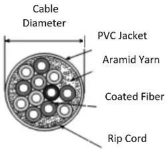
Figure 2 Non-utilized Premises Cable

4.2 Generally speaking, use the smallest grip which will fit over the cable's outer jacket without excessive difficulty.
Measure the cable diameter and determine the proper grip by locating the diameter in Table 1.
| Cable Diameter and Grip Size | ||
| If cable diameter is in the range of...... | Kellems part number | |
| 2.5 - 5.6mm (0.10 to 0.22in.) | 033-29-1182 | |
| 5.3 - 9.0mm (0.21 to 0.35in.) | 033-29-1182 | |
| 9.1 - 12.2mm (0.36 to 0.48in.) | 033-29-1184 | |
| 12.3 - 15.5mm (0.49 to 0.61in.) | 033-29-1185 | |
| 15.6 - 18.5mm (0.62 to 0.73in.) | 033-29-1186 | |
| 18.6 - 22.1mm (0.74 to 0.87in.) | 033-29-1187 | |
| 22.2 - 25.4mm (0.88 to 1.0in.) | 033-29-1188 | |
4.3 Once the proper grip is obtained, inspect it for damage broken wires, bulges due to stress, rust, etc. Grasp the pulling eye in one hand (gloves are recommended) and smooth out the mesh with the other, tightening the wires. Figure 4 illustrates the technique, which is critical when reusing grips.

natural_image
Illustration of two hands holding a rope tied with a string (no text or symbols)Figure 4
4.4 To ease installation, trim the end of the cable with side cutters to remove any protruding buffered fibers, yarn, or central member (Figure 5)

natural_image
Line drawing of a pliers or forceps being inserted into a tool (no text or symbols present)Figure 5
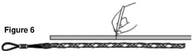
4.5 It is necessary to remove a section of outer jacket equal to half of the length of the mesh area of the grip. Mark this distance from the end of the cable with a permanent marker (Figure 6)
natural_image
Diagram showing a hand holding a pen over a wire or coiled cable, labeled 'Figure 6' (no text or symbols on the diagram itself)4.6 Use a pumping action to "walk" the grip over the cable by bringing your hands together and then relaxing them until the end of the grip is at least 7.5 cm (3 in.) beyond the mark made in step 4.5 (Figure 7)
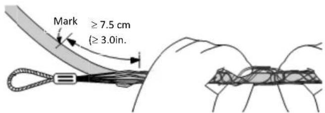
Figure 7
4.7 Follow the sheath removal procedure for the cable you are installing to remove the marked length of outer jacket (Figure 8).
For non-unitized cables, first remove 15 cm (6 in.) of jacket from the end of the cable. Tape the cable components together with vinyl electrical tape. Then remove the remaining jacket.

CAUTION: When making ring cuts with a hook blade or cable knife, do not cut all the way through the outer jacket-doing so may damage the sub units or other cable components which lie immediately below it.

natural_image
Illustration of two hands holding a cable with wires, no text or symbols presentFigure 8
4.8 Beginning at the end of the outer jacket, wrap one layer of friction tape over the entire length of the exposed cable core. The friction tape should follow the direction of the sun-units or buffered fibers twists.

IMPORTANT: Do not use black electrical tape in place of friction tape. Electrical tape has a slick outer surface and could affect the pulling grip's performance.

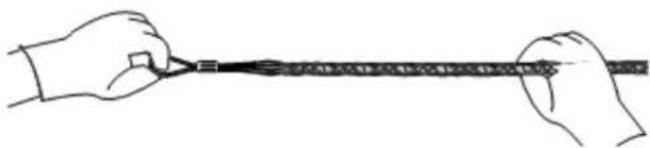
4.9 "Walk" grip over the friction tape-covered cable core. Smooth the mesh back over the cable core, moving from the pulling eye to the cable jacket. Tug on the grip to tighten it against the core (Figure 10)
natural_image
Line drawing of two hands holding a long, segmented object (no text or symbols)Figure 10
4.10 Starting at least 2.5 cm (1.0 in.) below the mesh on the cable jacket wrap vinyl tape TIGHTLY to the top of the grip. The mesh's imprint should show clearly through the tape. (Figure 11).
The tape must be tight because it helps compress the mesh again at the cable core.
Tug on the grip slightly to tighten it.

natural_image
Illustration of a coiled cable with a tape measure and coiled wire wrapped around it (no text or symbols)Figure 11
Note: When two or more vinyl tape layers are desired, always wrap the final, outside layer from the cable jacket to the pulling eye. This layers the tape like roofing shingles, so that it will not snag as it moves through the duct.
4.11 Connect the pulling eye to the appropriate ball bearing swivel and pulling tape. (Figure 12). The grip installation is now ready for the cable pull.

natural_image
Pure mechanical component diagram without any text, numbers, or symbolsFigure 12
Grip Removal
4.12 After completion of the pull, cut the cable 91 cm (36 in.) behind the grip. Place a protective cap over the exposed cable end and tape in place to prevent water intrusion. Store the coiled splicing slack so that it is protected from damage.
4.0 Interconnect Cable
This procedure is intended to be used with interconnect cables, including both duplex and simplex cable designs. Two simplex cables comprise a single duplex cable.
The length of cable sheath to be removed will depend on local company practices and specifications. Designate this distance from the end of the cable on the outer sheath.
4.1 Duplex Cable Preparation
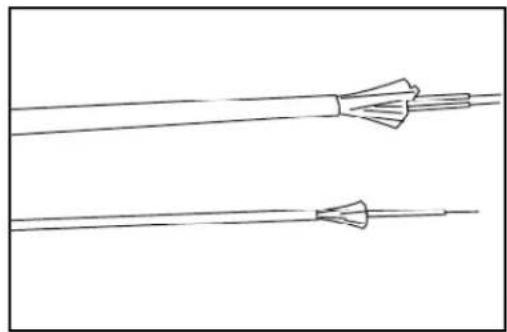
There are two types of duplex cables.
Sheathed Duplex
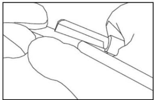
Enclosing two simplex cables in an outer sheath created a duplex cable. To prepare this type of cable, with a sheath knife, cut the outer jacket at the designated distance.
Gently flex the cable at the ring cut to separate or removal.
Remove and discard the sheath section. No more than eight inches of sheath should be removed at once. Therefore, eight-inch sections must be removed until the final desired length is achieved.
With the outer sheath the two internal simplex cables are not exposed. At this point advance to Section 4.2 for simplex cable preparation procedures.
natural_image
Pure diagram of two parallel wires with twisted leads, no text or symbols presentDuplex and simplex cables
natural_image
Line drawing of a hand holding a tool or tool, no text or symbols presentRinging a sheathed cable outer jacket with a sheath knife.

natural_image
Line drawing of a hand holding a small object, possibly a tool or device, with no visible text or symbols.Flexing the sheathed cable at the ring cut

natural_image
Line drawing of a hand holding a plant stem (no text or symbols)Removing the outer section of the jacket
Zip-cord Duplex Cables
Two simplex cables joined via a connecting membrane create a duplex cable. This type of duplex cable is referred to as zip-cord.
To prepare a zip-cord style duplex cable, use an approved sheath knife to carefully separate the duplex cable into two simplex cables. Cut the membrane connecting the two simplex cables. Approximately one inch is sufficient.
Firmly grasp the two separated simplex cables and pull them apart. They should separate easily.
Separate the duplex cable into two simplex cables for the distance designated by local splicing/termination guidelines and vendor specifications.
At this point, advance to Section 4.2 for Simplex Cable Preparation procedures.

natural_image
Line drawing of a hand holding a tool or wire, no text or symbols presentCutting the membrane connecting the two cables

natural_image
Line drawing of two hands holding a curved object, no text or symbols presentCarefully separating the two cables by pulling them apart
4.2 Simplex Cable Preparation
The length of sheath to be removed from each simplex cable will be determined by local splicing/termination guidelines and vendor specifications.
The manufacturer of the connector type being installed specifies the correct removal length for each cable component. Information similar to the following illustration should be provided with the connector.

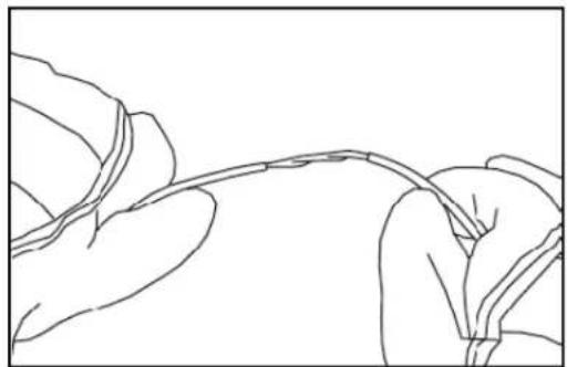
Using an approved set of strippers that do not come close to a diameter small enough to damage the fiber, select one simplex cable and cut the jacket at the length as specified by the connector manufacturer.
Remove the length of outer jacket. This will expose the tight-buffered fiber and the strength member yarn. Separate the strength member yarn from the tight-buffered fiber.
Cut off the strength members leaving the length specified by the connector manufacturer.
At this point advance to Section 7.0 for Fiber Preparation procedures.

natural_image
Simple line drawing of a cable or wire with connectors (no text or symbols)Simplex cable

natural_image
Line drawing of hands using pliers to handle a thin wire (no text or symbols)Cutting the simplex jacket to expose the tight-buffered fiber
natural_image
Line drawing of a plant stem with leaves, no text or symbols presentRemoving the outer length of the simplex jacket

natural_image
Line drawing of two hands holding a thin wire or wire, no text or symbols presentCutting the strength member yarns
5.0 Distribution Cable (24 Fibers or less Preparation)
This procedure is intended for use with distribution cable with 24 or fewer tight-buffered fibers. The 24-fiber design consists of a core of 12 tight-buffered fibers around an upjacketed central strength member. Stranded around this core are 12 more fibers with filler units to complete the layer. Strength member yarns and a jacket cover the core.
The 12-fiber design is similar to the 24-fiber design without the outer layer of fibers. For these procedures the 24-fiber design will be shown. The sheath removal for the 12-fiber design is identical with the exception of the outer core layer of fibers.
5.1 Jacket Preparation
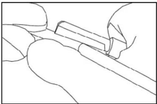
The length of cable sheath to be removed will depend on local company practices and vendor specifications. If not otherwise specified, six feet should be sufficient. Designate this distance from the end of the cable on the outer sheath. Using an approved sheath knife, "ring" the circumference of the jacket at the designated distance.
Using a sheath knife, "ring" the circumference of the jacket about six to eight inches from the end of the cable.
Gently flex the cable at the cut to separate for removal.
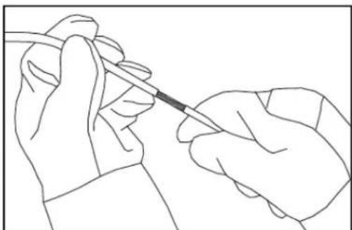
The end piece of the jacket can be removed and discarded. This will expose the strength member yarns and ripcord.
natural_image
Line drawing of a hand holding a tool, no text or symbols presentRinging the cable with a sheath knife

natural_image
Line drawing of a stylized human hand and wrist (no text or symbols)Flexing the cable at the ring cut to separate sheath sections
natural_image
Line drawing of a gloved hand holding a medical needle, no text or symbols presentRemoving the outer cable sheath section

natural_image
Line drawing of a hand holding a thin, elongated object (no text or symbols)Exposing the ripcord
Grasp and wrap the ripcord around the needle-nose pliers.
Pull the ripcord back to the first predetermined ring cut.
Carefully separate the strength member yarns from the core and cit to the length prescribed by local practices and vendor specifications.
At this point advance to Section 7.0 for Fiber Preparation procedures.

natural_image
Line drawing of a hand holding a pen or tool, no text or symbols presentGrasping the ripcord with needle nose pliers

natural_image
Line drawing of a hand holding a tool or object, possibly a tool or device, with no visible text or symbols.Pulling the ripcord to the predetermined ring cut

natural_image
Line drawing of a hand holding a thin tool over a textured surface (no text or symbols)Removing the split cable sheath

natural_image
Line drawing of a hand using scissors to cut a piece of wood (no text or symbols)Cutting the strength member yarns
6.0 Distribution Cable (Greater than 24 Fibers) Preparation
This procedure is intended for use with distribution cable with more than 24 fibers. The 72-fiber version of this design is used here for demonstration purposes. The procedure explained here will work with all other distribution cable with more than 24 fibers.
The 72-fiber cable consists of six jacketed unites stranded around an upjacketed CSM. There is tape and a jacket round each unit. Around the core of the six units are stranded strength member yarns – on top of which the outer jacket is applied.
6.1 Jacket Preparation
The length of cable sheath to be removed will depend on local company practices and vendor specifications. Designate this distance from the end of the cable on the outer sheath.
Using the approved sheath knife, "ring" the circumference of the outer jacket at the designated distance.
Using the sheath knife, "ring" the circumference of the outer jacket about six to eight inches from the end of the cable.
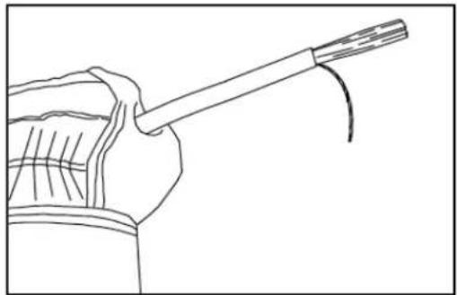
The end piece of jacket can be removed and discarded. This will expose the strength member yarns and ripcord.

natural_image
Line drawing of hands holding a tool or wire (no text or symbols)Ringing the cable sheath with a sheath knife

natural_image
Line drawing of a hand holding a curved object, possibly a tool or device (no text or symbols present)Flexing the cable at ring cut to separate sheath sections
natural_image
Line drawing of a hand holding a cable with a string, no text or symbols presentExposing the ripcord after removal of jacket end piece
Grasp and wrap the ripcord around the needle-nose pliers.
Pull the ripcord back to the first predetermined ring cut.
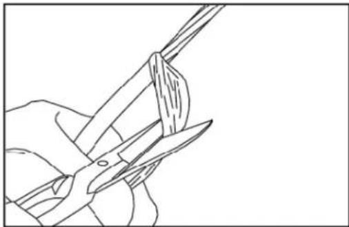
If a ripcord is not provided carefully slit the outer jacket to the predetermined ring cut using a sheath knife.
Remove this length of the jacket and discard it.
Separate the strength member yarns from the core and cut to the length prescribed by local company practices and vendor specifications.

natural_image
Line drawing of two figures in martial arts attire, one holding a staff (no text or symbols)Grasping the ripcord with needle-nose pliers and pulling back to predetermined ring cut
natural_image
Line drawing of a hand using scissors to cut a piece of wood (no text or symbols)Removing the split cable sheath

natural_image
Line drawing of a hand using scissors to cut or draw a piece of material (no text or symbols)Cutting the strength member yarns
The core of the six jacketed units wrapped with a clear tape. This tape can now be unwrapped and discarded. This will expose the individual jacketed units for preparation.
The six jacketed units are stranded around the CSM. Unwind the units to expose the CSM.
Using approved cutters cut the CSM to the desired length for termination.

natural_image
Line drawing of a fish tail with visible fins and segmented body (no text or symbols)Unwinding the clear tape

natural_image
Line drawing of a hand using a pliers to cut a wire (no text or symbols)Exposing the central strength member

natural_image
Line drawing of a hand using a pliers to cut a wire (no text or symbols)Cutting the central strength member
6.2 Unit Preparation
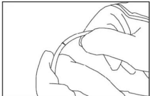
The length of unit jacket to be removed will depend on local company practices and vendor specification. It is important to use care to avoid damaging the tight-buffered fibers in the core of the unit and also to avoid cutting the ripcord.
Using the sheath knife gently "ring" the circumference of the unit jacket about four to six inches from the end of the unit. Again, it is very important to use care to avoid damaging the tight-buffered fibers in the core of the unit and also to avoid cutting the ripcord.
Gently flex the unit at the cut to separate for removal.
The end piece of unit jacket can be removed and discarded. This will expose the ripcord and the clear tape wrapped around the core.

natural_image
Line drawing of a hand holding a tool, no text or symbols presentCut the outer strength members
natural_image
Line drawing of a hand holding a small object, possibly a tool or device, with no visible text or symbols.Flexing the unit of the ring cut to separate jacket sections

natural_image
Line drawing of two gloved hands holding a medical needle (no text or symbols)Removing the end piece of the unit jacket
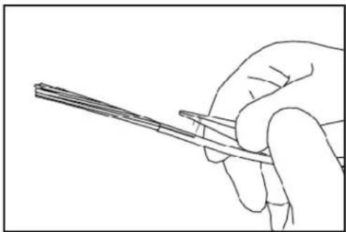
Grasp and wrap the ripcord around the needle-nose pliers.
Pull the ripcord back to the predetermined length. This will depend on local company practices and vendor specifications. Peel the jacket away to this point.
Using the approved snips or scissors cut this length of jacket away. Use care to avoid cutting any of the tight-buffered fibers.
The unit's tight-buffered fibers are surrounded with strength member yarns. Carefully separate the tight-buffered fibers from the strength member yarns.
Using approved snips or scissors cut the strength member yarns to the desired length for termination.
At this point advance to Section 7.0 for fiber Preparation procedures.
natural_image
Line drawing of a hand holding a pen, no text or symbols presentGrasping and pulling the ripcord with needle-nose pliers

natural_image
Line drawing of a hand holding a thin wire or fiber, no text or symbols presentExposing the ripcord

natural_image
Line drawing of a hand using scissors to cut a piece of wood (no text or symbols)Peeling off the unit jacket
7.0 Fiber Preparation
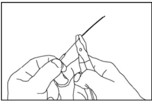
Using an approved stripping tool that scores the 900 m diameter tight-buffered coating, but does not touch the 125 m diameter of the fiber, remove the tight-buffered coating. For best results, strip and remove two inches or less at a time. When stripping either the tight-buffered coating or the fiber's coating, hold the fiber carefully to avoid tight bends, while placing the fiber under tension. Small bend diameters and abrupt high stress can damage or break the fiber.
With the fibers now exposed and accessible for termination refer to local splicing/termination guidelines and vendor specification.
Refer back to Section 4.2 Simplex Cable Preparation for an example of manufacturer supplied connector termination instructions.
natural_image
Line drawing of hands using a tool to draw or wire (no text or symbols)Removing the tight buffering

- Table of Contents
- DISCLAIMER OF WARRANTIES AND LIMITATION OF LIABILITIES
- General Information
- Preparation Notes
- Pulling Procedure
- Tools and Materials
- General
- Precautions
- General Precautions
- Safety Glasses
- Cable Handling Precaution
- Tools and Materials
- Pulling Grip Selection and Installation
- Prior to installation, the proper size grip must be chosen for the cable to be pulled.
- Generally speaking, use the smallest grip which will fit over the cable's outer jacket without excessive difficulty.
- Grip Removal
- Interconnect Cable
- Duplex Cable Preparation
- Sheathed Duplex
- Zip-cord Duplex Cables
- Simplex Cable Preparation
- Distribution Cable (24 Fibers or less Preparation)
- Jacket Preparation
- Distribution Cable (Greater than 24 Fibers) Preparation
- Jacket Preparation
- Unit Preparation
- Fiber Preparation
Brand : Panduit
Model : FSDP912Y
Category : Computer Cable