AIMB-592 - Motherboard Advantech - Free user manual and instructions
Find the device manual for free AIMB-592 Advantech in PDF.

User questions about AIMB-592 Advantech
0 question about this device. Answer the ones you know or ask your own.
Ask a new question about this device
Download the instructions for your Motherboard in PDF format for free! Find your manual AIMB-592 - Advantech and take your electronic device back in hand. On this page are published all the documents necessary for the use of your device. AIMB-592 by Advantech.
USER MANUAL AIMB-592 Advantech
natural_image
Illustration of four electronic circuit boards with white outlines on a purple background (no text or symbols)AIMB-592
AMD EPYC 7003 Zen 3 Core, MicroATX with 4 PCIe X 16 Slots, 2 10GbE LANs, 2 2.5GbE LANs, 5 USB 3.2 Gen1, IPMI 2.0
Copyright
The documentation and the software included with this product are copyrighted 2023 by Advantech Co., Ltd. All rights are reserved. Advantech Co., Ltd. reserves the right to make improvements in the products described in this manual at any time without notice. No part of this manual may be reproduced, copied, translated or transmitted in any form or by any means without the prior written permission of Advantech Co., Ltd. Information provided in this manual is intended to be accurate and reliable. However, Advantech Co., Ltd. assumes no responsibility for its use, nor for any infringements of the rights of third parties, which may result from its use.
Acknowledgments
AMI is a trademark of American Megatrends Inc.
IBM and PC are trademarks of International Business Machines Corporation.
AMD EPYC 7003 Zen 3 Core Series is trademark of AMD Corporation.
All other product names or trademarks are properties of their respective owners.
Product Warranty (2 years)
Advantech warrants to you, the original purchaser, that each of its products will be free from defects in materials and workmanship for two years from the date of purchase.
This warranty does not apply to any products which have been repaired or altered by persons other than repair personnel authorized by Advantech, or which have been subject to misuse, abuse, accident or improper installation. Advantech assumes no liability under the terms of this warranty as a consequence of such events.
Because of Advantech's high quality-control standards and rigorous testing, most of our customers never need to use our repair service. If an Advantech product is defective, it will be repaired or replaced at no charge during the warranty period. For out-of-warranty repairs, you will be billed according to the cost of replacement materials, service time and freight. Please consult your dealer for more details.
If you think you have a defective product, follow these steps:
-
Collect all the information about the problem encountered. (For example, CPU speed, Advantech products used, other hardware and software used, etc.) Note anything abnormal and list any onscreen messages you get when the problem occurs.
-
Call your dealer and describe the problem. Please have your manual, product, and any helpful information readily available.
-
If your product is diagnosed as defective, obtain an RMA (return merchandise authorization) number from your dealer. This allows us to process your return more quickly.
-
Carefully pack the defective product, a fully-completed Repair and Replacement Order Card and a photocopy proof of purchase date (such as your sales receipt) in a shippable container. A product returned without proof of the purchase date is not eligible for warranty service.
-
Write the RMA number visibly on the outside of the package and ship it prepaid to your dealer.
Part No. 2006059200 Edition 1
Printed in China July 2023
Declaration of Conformity
FCC Class B
Note: This equipment has been tested and found to comply with the limits for a Class B digital device, pursuant to part 15 of the FCC Rules. These limits are designed to provide reasonable protection against harmful interference in a residential installation. This equipment generates, uses and can radiate radio frequency energy and, if not installed and used in accordance with the instructions, may cause harmful interference to radio communications. However, there is no guarantee that interference will not occur in a particular installation. If this equipment does cause harmful interference to radio or television reception, which can be determined by turning the equipment off and on, the user is encouraged to try to correct the interference by one or more of the following measures:
■ Reorient or relocate the receiving antenna.
■ Increase the separation between the equipment and receiver.
■ Connect the equipment into an outlet on a circuit different from that to which the receiver is connected.
Consult the dealer or an experienced radio/TV technician for help.
CPU Compatibility
CPU Family Core Number TDP(W) Max. Speed L3 Cache
| 7313P 16 155W 3.7GHz 128MB | |
| 7543P 32 225W 3.7GHz 256MB | |
| 7713P 64 225W 3.675GHz | 256MB |
Memory Compatibility
| Category | Speed | Capacity | Vendor | Module_PN | Chip_PN | ADVANTECH P/N | ECC | Result |
| DDR5 | 4800 | 32GB | Advantech | SQR-SD5N32G4K8MNAB | IVA45D8BNJ | SQR-SD5N32G4K8MNAB | N | PASS |
| DDR5 | 4800 | 16GB | Advantech | SQR-SD5N16G4K8MNAB | 2AA45D8BNJ | SQR-SD5N16G4K8MNAB | N | PASS |
Ordering Information
| P/N AIMB-592SF-00A1 AIMB-592SL-00A1 | ||
| USB 3.2 (Rear) 4 4 | ||
| USB 3.2 (Internal) 1 1 | ||
| VGA 1 1 | ||
| PCIe x16 Gen4 4 4 | ||
| DDR4 Memory 6 6 | ||
| 10GbE LAN | 2 0 | |
| 2.5GbE LAN | 2 2 | |
| IPMI2.0 | Yes | No |
| BMC | 1 (AST2500) | 1 (AST2510)* |
| BMC LAN | 1 0 | |
| SATA III | 8 8 | |
| M.2 M-key | 1 1 | |
| TPM | 1 1 | |
| Slimline | 2 (PCIex4) | 2 (PCIex4) |
* No BMC function
Initial Inspection
Before you begin installing your motherboard, please make sure that the following materials have been shipped:
■ 1 x AIMB-592 AMD EPYC 7003 Zen 3 Core MicroATX Motherboard
4 x SATA HDD cable
■ 1 x I/O port bracket
1 x Warranty card
2 x M.2 screws
If any of these items are missing or damaged, contact your distributor or sales representative immediately. We have carefully inspected the AIMB-592 mechanically and electrically before shipment. It should be free of marks and scratches and in perfect working order upon receipt. As you unpack the AIMB-592, check it for signs of shipping damage. (For example, damaged box, scratches, dents, etc.) If it is damaged or it fails to meet the specifications, notify our service department or your local sales representative immediately. Also notify the carrier. Retain the shipping carton and packing material for inspection by the carrier. After inspection, we will make arrangements to repair or replace the unit.
Contents
Chapter 1 General Information ....1
1.1 Introduction ...... 2
1.2 Features 2
1.3 Specifications 2
1.3.1 Processor.... 2
1.3.2 Memory 2
1.3.3 Input/Output 2
1.3.4 Graphics.... 2
1.3.5 Ethernet LAN 2
1.3.6 Industrial Features ...... 3
1.3.7 Mechanical and Environmental Specifications.... 3
1.4 Jumpers and Connectors .... 3
1.5 Board layout: Jumper and Connector Locations 3
Figure 1.1 Board Layout 3
Figure 1.2 Rear I/O of the Two SKUs 4
Table 1.1: Jumper Setting List....4
Table 1.2: Connector / Header List: 4
1.6 AIMB-592 Board Diagram 6
Figure 1.3 AIMB-592 Board Diagram 6
1.7 Safety Precautions 6
1.8 Jumper Settings 7
1.8.1 How to Set Jumpers....7
1.8.2 CMOS Clear (JCMOS1)....7
Table 1.3: JCMOS1 7
1.9 System Memory 7
1.10 Memory Installation Procedures....7
1.11 Processor Installation....8
Chapter 2 Connecting Peripherals ....13
2.1 Introduction ...... 14
2.2 LAN and USB Ports (LAN1_USB12/ LAN2_USB34/ LAN3_4/LAN5) ..... 14
2.3 VGA and Serial Ports (VGA1/COM1).... 15
2.4 BMC ROM socket (BMC_SKT1) 15
2.5 BIOS SPI ROM socket (BIOS SKT1) 16
2.6 Battery Holder (BAT1).... 16
2.7 LPC Connector (LPC1) 17
2.8 PCIe Expansion Slot (PCIEX16_SLOT1/ PCIEX16_SLOT2/ PCIEX16_SLOT3/ PCIEX16_SLOT4).... 17
2.9 System Error LED wafer (BMC_SYSLED1).... 18
2.10 PMBus wafer (PMBUS1).... 19
2.11 Hardware SMBUS (SMBUS1).... 19
2.12 Front Panel3 (JFP3).... 20
2.13 Graphics Card 12V slot (PCIE_SLOT12V1) 20
2.14 System FAN Connector (SYSFAN1/SYSFAN2/SYSFAN3/SYSFAN4) .. 21
2.15 Serial General Purpose I/O Connector (SGPIO1).... 23
2.16 Serial ATA Interface Connector (SATA1\~8).... 23
2.17 CPU Fan Connector (CPUFAN1).... 24
2.18 NGFF M.2 M-Key (NGFF_M1).... 25
2.19 Slimline SAS 4i Connector (SAS1/SAS2) 25
2.20 General purpose I/O Connector (GPIO1).... 26
2.21 USB3.2 Gen1 vertical connector (USB5) 26
2.22 DDR4 RDIMM slot (DIMME1/ DIMMH1/ DIMMG1/ DIMMA1/ DIMMD1/ DIMMC1).... 27
Chapter 3 BIOS and BMC Operation.... 31
3.1 Introduction ...... 32
3.2 BIOS Setup 32
3.2.1 Main Menu 33
3.2.2 Advanced BIOS Features 34
3.2.3 Chipset Configuration Setting 59
3.2.4 Security Setting....63
3.2.5 Boot Setting 64
3.2.6 Save & Exit 65
3.2.7 Event Logs....66
3.2.8 Server Mgmt 68
3.2.9 BMC - Setting of WEB Browser 73
Chapter 4 Software Introduction & Service ..... 81
4.1 Introduction 82
4.2 Value-Added Software Services 82
4.2.1 Software API 82
4.2.2 Software Utility....84
Chapter 5 Chipset Software Installation Utility 85
5.1 Before You Begin....86
5.2 Introduction 86
5.3 Windows Series Driver Setup 86
Chapter 6 LAN Configuration ...... 87
6.1 Introduction 88
6.2 Windows Series Driver Setup 88
Appendix A Pin Assignments.... 89
A.1 CMOS Clear Jumper (JCMOS1)....90
Table A.1: CMOS Clear Jumper (JCMOS1) 90
A.2 Front Panel1 + Front Panel2 header (JFP1+JFP2) 90
Table A.2: Front Panel1 + Front Panel2 header (JFP1+JFP2).. 90
A.3 Case open pin header (JCASE1)....90
Table A.3: Case open pin header (JCASE1) 90
A.4 ATX 12V IN connector (ATX12V1/ ATX12V2)ATX/AT Mode Selection (PSON1) ....
Table A.4: ATX 12V IN connector (ATX12V1/ ATX12V2)ATX/AT Mode Selection (PSON1) 91
A.5 ATX 24pin IN connector (ATXPWR1) 91
Table A.5: ATX 24pin IN connector (ATXPWR1) 92
A.6 GPIO header (GPIO1) 92
Table A.6: GPIO header (GPIO1).... 92
A.7 EC programing header (SCN1)....93
Table A.7: EC programing header (SCN1) 93
A.8 System FAN Connector (SYSFAN1/SYSFAN2/SYSFAN3/SYSFAN4) .. 93
Table A.8: System FAN Connector (SYSFAN1).... 93
Table A.9: System FAN Connector (SYSFAN2).... 94
Table A.10:System FAN Connector (SYSFAN3).... 94
Table A.11:System FAN Connector (SYSFAN4) 95
A.9 CPU FAN connector (CPUFAN1) 95
Table A.12:CPU FAN connector (CPUFAN1).... 95
A.10 Serial GPIO (SGPIO1) 96
Table A.13:Serial GPIO (SGPIO1).... 96
A.11 System Error Led wafer (BMC_SYSLED1)....96
Table A.14:System Error Led wafer (BMC_SYSLED1) 96
A.12 PMBus wafer (PMBUS1)....97
Table A.15: PMBus wafer (PMBUS1) 97
A.13 HW SMBUS (SMBUS1) 97
Table A.16:HW SMBUS (SMBUS1)....97
A.14 Front Panel3 (JFP3)....98
Table A.17:Front Panel3 (JFP3) 98
A.15 Graphics Card 12V slot (SLOT12V1)....98
Table A.18: Graphics Card 12V slot (SLOT12V1) 98
Chapter 1
General Information
1.1 Introduction
The AIMB-592 motherboard utilizes the AMD EPYC 7003 Zen 3 Core processor, catering to industrial applications that necessitate high-performance computing and advanced power management capabilities. It supports the AMD EPYC 7003 Zen 3 Core, boasting a sizable 256MB L3 cache and DDR4 3200 MHz with a maximum capacity of 768GB (6 x 128GB per slot). The motherboard offers extensive I/O connectivity, including 4 x PCIe16 slots, up to 2 x 10GbE LAN, 2 x 2.5GbE LAN, 5 x USB 3.2 Gen2, 8 x SATA III ports, and IPMI2.0.
1.2 Features
Rich I/O connectivity: up to dual 10GbE LAN and dual 2.5 Gbe LAN via PCIe x1 bus, 4 x PCIe x16 slot (Gen 4), 5 USB 3.2 Gen1, 2 slimline via PCIex4 bus.
Standard Micro ATX form factor with industrial features: The AIMB-592 is a full featured Micro ATX motherboard with balanced expandability and performance.
■ Diverse Storage Devices: SATA HDD, M.2 M-key SSD
■ Optimized Integrated Graphics: no integrated graphic.
1.3 Specifications
1.3.1 Processor
■ CPU: AMD EPYC™ 7003 Series Processors
BIOS: AMI EFI 256 Mb SPI (with Lotus SPI socket)
■ SATA hard disk drive interface: On-board SATA connectors with data trans- mission rate up to 600 MB
1.3.2 Memory
■ RAM: Up to 768 GB in six slots, 288-pin DIMM sockets. Supports dual-channel up to DDR4 3200MHz RDIMM.
– The ECC compatibility of AIMB-592 is supported.
1.3.3 Input/Output
■ PCIe slot: 4 PCIe x16 expansion slot
■ Serial port: a serial port of RS-232
USB port: Supports up to 5 USB 3.2 Gen1 ports with transmission rates up to 5Gbps.
■ GPIO: AIMB-592 supports 8-bit GPIO from super I/O for general-purpose control application.
1.3.4 Graphics
■ Controller: ASPEED AST2500/AST2510 BMC Chip
■ VGA: VGA up to 1920x1200@60Hz
1.3.5 Ethernet LAN
■ Supports up to two 10/100/1000/2500 Mbps Ethernet port (s) via PCI Express x1 bus and two 100/1000/10000 Mbps Ethernet port (s) via PCI Express x4 bus
Controller: LAN1/LAN2: Intel I226LM(AIMB-592SF/AIMB-592SL)LAN3/LAN4: Intel X550-AT (AIMB-592SF); LAN5: Realtek 8211FSI(AIMB-592SF)
1.3.6 Industrial Features
■ Watchdog timer: Can generate a system reset. The watchdog timer is programmable, with each unit equal to one second or one minute (255 levels).
1.3.7 Mechanical and Environmental Specifications
- Operating temperature: 0 \~ 60°C (32 \~ 140°F, depending on CPU).
■ Storage temperature: -40 \~ 85°C (-40 \~ 185°F).
■ Power supply voltage: +5V, +12V, +3.3V, +5 VSB, +12V_8P
■ Power consumption:
+5 V 3.3 V 12 V 12 V(8-pin) +5VSB
13.3A 36.2A 33.5A 13.7A 2A
Measure the maximum current value which system under maximum load (CPU: Top speed, RAM & Graphic: Full loading)
■ Board size: 244 mm x 244 mm (9.6" x 9.6")
■ Board weight: 0.3 kg.
1.4 Jumpers and Connectors
Connectors on the AIMB-592 motherboard link it to devices such as hard disk drives and a keyboard. In addition, the board has a number of jumpers used to configure your system for your application.
The tables below list the function of each of the board jumpers and connectors. Later sections in this chapter give instructions on setting jumpers. Chapter 2 gives instructions for connecting external devices to your motherboard.
1.5 Board layout: Jumper and Connector Locations
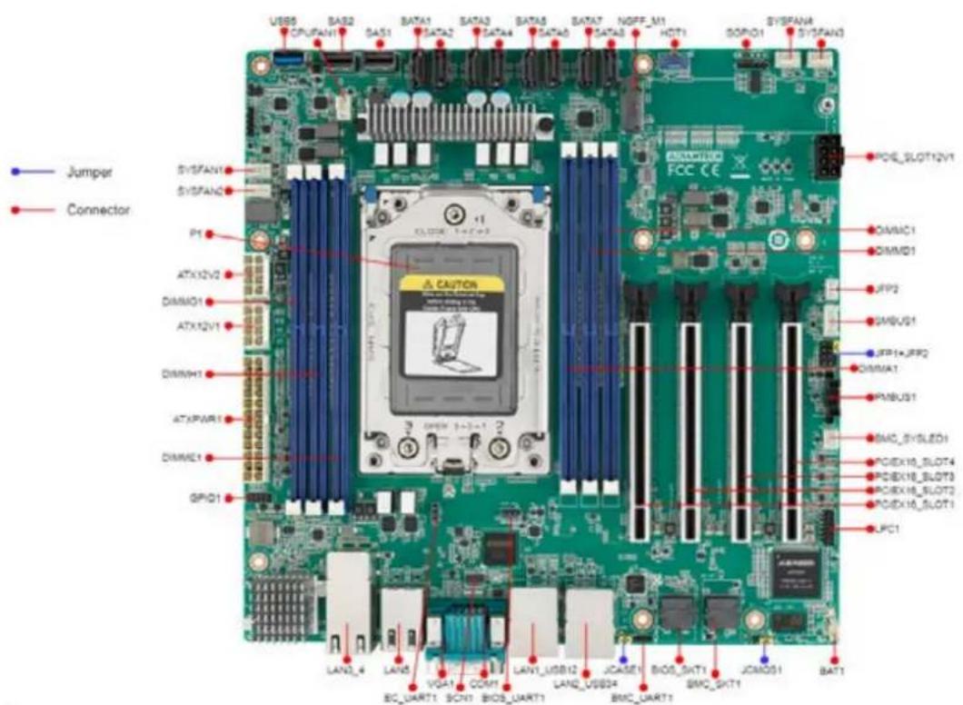
text_image
Jumper Connector SYSFAN1 SYSFAN2 P1 ATX12V2 DIMM01 ATX12V1 DIMWH1 ATXPAR1 DIMME1 GPIQ1 LAN2_4 LAN5 VGA1 COM1 LAN1_USB12 LAN2_USB34 BMC_UART1 JCASE1 BIOS_SHT1 BMC_SHT1 JCMOS1 BAT1 USB5 CPU/FAN1 SAS1 SATA1 SATA2 SATA3 SATA4 SATA5 SATA6 SATA7 SATA8 NGFF_M1 HDT1 GOP01 SYSFAN3 POIE_SLOT12V1 DIMM01 DIMM01 JFP2 GMBUS1 JFP1+JFP2 DIMMA1 PMBUS1 BMC_SYSLED1 PCIEX18_SLOT4 PCIEX18_SLOT3 PCIEX18_SLOT2 PCIEX18_SLOT1 LPC1Figure 1.1 Board Layout
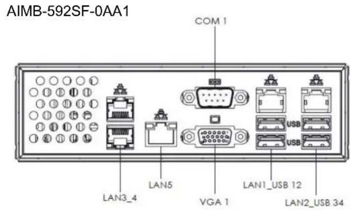
text_image
AIMB-592SF-0AA1 COM 1 LAN3_4 LAN5 VGA 1 LAN1_USB 12 LAN2_USB 34
text_image
AIMB-592SL-0AA1 COM 1 VGA 1 LAN1_USB 12 LAN2_USB 34Figure 1.2 Rear I/O of the Two SKUs
Table 1.1: Jumper Setting List
| Description Part Reference |
| 1 Clear CMOS jumper JCMOS1 |
| 2 Case open pin header JCASE1 |
| 3 Front Panel1 + Front Panel2 header JFP1+JFP2 |
Table 1.2: Connector / Header List:
| Description Part Reference | ||
| 1 10G LAN Port *2 LAN3_4 | ||
| 2 BMC LAN LAN5 | ||
| 3 BMC VGA VGA1 | ||
| 4 COM Port COM1 | ||
| 5 2.5G LAN+USB3.2 Gen1 *2 LAN1_USB12 | ||
| 6 2.5G LAN+USB3.2 Gen1 *2 LAN2_USB34 | ||
| 7 BIOS SPI ROM socket BIOS_SKT1 | ||
| 8 BMC ROM socket | BMC_SKT1 | |
| 9 Battery Holder | BAT1 | |
| 10 LPC Debug header | LPC1 | |
| 11 PCIe x16 slot | PCIEX16_SLOT1 | |
| 12 PCIe x16 slot | PCIEX16_SLOT2 | |
| 13 PCIe x16 slot | PCIEX16_SLOT3 | |
Table 1.2: Connector / Header List:
| 14 PCIe x16 slot PCIEX16_SLOT4 | |
| 15 System Error Led wafer BMC_SYSLED1 | |
| 16 PMBus wafer PMBUS1 | |
| 17 HW SMBUS SMBUS1 | |
| 18 Front Panel3 JFP3 | |
| 19 Graphics Card 12V slot PCIE_SLOT12V1 | |
| 20 System FAN3 connector SYSFAN3 | |
| 21 System FAN4 connector SYSFAN4 | |
| 22 Serial GPIO SGPIO1 | |
| 23 AMD Debug connector HDT1 | |
| 24 M.2 M key 2280 slot NGFF_M1 | |
| 25 SATA connector SATA8 | |
| 26 SATA connector SATA7 | |
| 27 SATA connector SATA6 | |
| 28 SATA connector SATA5 | |
| 29 SATA connector SATA4 | |
| 30 SATA connector SATA3 | |
| 31 SATA connector SATA2 | |
| 32 SATA connector SATA1 | |
| 33 Slimline SAS 4i connector SAS1 | |
| 34 Slimline SAS 4i connector SAS2 | |
| 35 CPU FAN connector | CPUFAN1 |
| 36 USB3.2 Gen1 vertical connector | USB5 |
| 37 System FAN1 connector SYSFAN1 | |
| 38 System FAN2 connector SYSFAN2 | |
| 39 ATX 12V IN connector | ATX12V2 |
| 40 ATX 12V IN connector | ATX12V1 |
| 41 ATX 24pin IN connector | ATXPWR1 |
| 42 GPIO header | GPIO1 |
| 43 DDR4 RDIMM slot | DIMME1 |
| 44 DDR4 RDIMM slot | DIMMH1 |
| 45 DDR4 RDIMM slot | DIMMG1 |
| 46 DDR4 RDIMM slot | DIMMA1 |
| 47 DDR4 RDIMM slot | DIMMD1 |
| 48 DDR4 RDIMM slot | DIMMC1 |
| 49 CPU socket | P1 |
| 50 EC programing header SCN1 | |
1.6 AIMB-592 Board Diagram
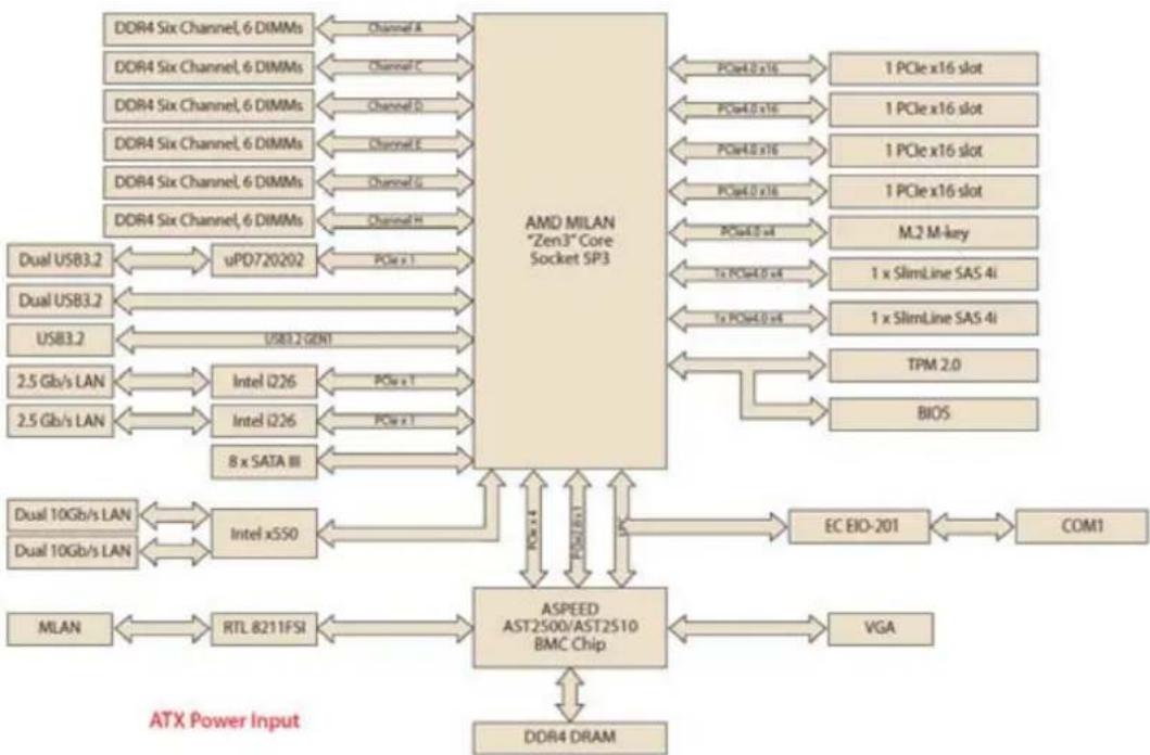
flowchart
graph TD
    A["DDR4 Six Channel, 6 DIMMs"] -->|Channel A| B["AMD MILAN "Zen3" Core Socket SP3"]
    C["DDR4 Six Channel, 6 DIMMs"] -->|Channel C| B
    D["DDR4 Six Channel, 6 DIMMs"] -->|Channel D| B
    E["DDR4 Six Channel, 6 DIMMs"] -->|Channel E| B
    F["DDR4 Six Channel, 6 DIMMs"] -->|Channel F| B
    G["DDR4 Six Channel, 6 DIMMs"] -->|Channel G| B
    H["DDR4 Six Channel, 6 DIMMs"] -->|Channel H| B
    I["Dual USB3.2"] --> J["uPD720202"]
    K["Dual USB3.2"] --> L["USB3.2 GEN1"]
    M["USB3.2"] --> N["2.5 Gb/s LAN"]
    O["2.5 Gb/s LAN"] --> P["Intel i226"]
    Q["2.5 Gb/s LAN"] --> R["Intel i226"]
    S["8 x SATA III"] --> T["ASPEED AST2500/AST2510 BMC Chip"]
    U["Dual 10Gb/s LAN"] --> V["Intel xSSO"]
    W["Dual 10Gb/s LAN"] --> X["MTL 8211FSI"]
    Y["MLAN"] --> Z["RTL 8211FSI"]
    AA["VGA"] --> AB["EC EIO-201"]
    AC["BIOS"] --> AD["TPM 2.0"]
    AE["M.2 M-key"] --> AF["1x SlimLine SAS 4i"]
    AG["1x SlimLine SAS 4i"] --> AH["1x SlimLine SAS 4i"]
    AI["1 PCIe x16 slot"] --> AJ["PCIe4.0 x16"]
    AK["1 PCIe x16 slot"] --> AL["PCIe4.0 x16"]
    AM["1 PCIe x16 slot"] --> AN["PCIe4.0 x16"]
    AO["M.2 M-key"] --> AP["PCIe4.0 x4"]
    AQ["1x SlimLine SAS 4i"] --> AR["PCIe4.0 x4"]
    AS["1x SlimLine SAS 4i"] --> AT["PCIe4.0 x4"]
    AU["BIOS"] --> AV["PCIe4.0 x4"]
    AW["PCIe x1.4"] --> AX["ASPEED AST2500/AST2510 BMC Chip"]
    AX --> AXA["PCle x1"]
    AX --> AXB["PCle x1"]
    AX --> AXC["PCle x1"]
    AX --> AXD["PCle x1"]
    AX --> AXE["PCle x1"]
    AX --> AXF["PCle x1"]
    AX --> AXG["PCle x1"]
    AX --> AXH["PCle x1"]
    AX --> AXI["PCle x1"]
    AX --> AXJ["PCle x1"]
    AX --> AXK["PCle x1"]
    AX --> AXL["PCle x1"]
    AX --> AXM["PCle x1"]
    AX --> AXN["PCle x1"]
    AX --> AXO["PCle x1"]
    AX --> AXP["PCle x1"]
    AX --> AXQ["PCle x1"]
    AX --> AXR["PCle x1"]
    AX --> AXS["PCle x1"]
    AX --> AXT["PCle x1"]
    AX --> AXU["PCle x1"]
    AX --> AXV["PCle x1"]
    AX --> AXW["PCle x1"]
    AX --> AXX["PCle x1"]
    AX --> AXY["PCle x1"]
    AX --> AXZ["PCle x1"]
    AX --> AXA
    AX --> AXB
    AX --> AXC
    AX --> AXD
    AX --> AXE
    AX --> AXF
    AX --> AXG
    AX --> AXH
    AX --> AXI
    AX --> AXJ
    AX --> AXK
    AX --> AXL
    AX --> AXM
    AX --> AXN
    AX --> AXO
Figure 1.3 AIMB-592 Board Diagram
1.7 Safety Precautions
Warning! Always completely disconnect the power cord from chassis whenever you work with the hardware. Do not make connections while the power is on. Sensitive electronic components can be damaged by sudden power surges. Only experienced electronics personnel should open the PC chassis.
Caution! Always ground yourself to remove any static charge before touching the motherboard. Modern electronic devices are very sensitive to electrostatic discharges. As a safety precaution, use a grounding wrist strap at all times. Place all electronic components on a static-dissipative surface or in a static-shielded bag when they are not in the chassis.
Caution! The computer is provided with a battery-powered real-time clock circuit. There is a danger of explosion if battery is incorrectly replaced. Replace only with same or equivalent type recommended by the manufacturer. Discard used batteries according to manufacturer's instructions.
Caution! There is a danger of a new battery exploding if it is incorrectly installed. Do not attempt to recharge, force open, or heat the battery. Replace the battery only with the same or equivalent type recommended by the manufacturer. Discard used batteries according to the manufacturer's instructions.
1.8 Jumper Settings
This section provides instructions on how to configure your motherboard by setting the jumpers. It also includes the motherboard's default settings and your options for each jumper.
1.8.1 How to Set Jumpers
You can configure your motherboard to match the needs of your application by setting the jumpers. A jumper is a metal bridge that closes an electrical circuit. It consists of two metal pins and a small metal clip (often protected by a plastic cover) that slides over the pins to connect them. To "close" (or turn ON) a jumper, you connect the pins with the clip. To "open" (or turn OFF) a jumper, you remove the clip. Sometimes a jumper consists of a set of three pins, labeled 1, 2, and 3. In this case you connect either pins 1 and 2, or 2 and 3. A pair of needle-nose pliers may be useful when setting jumpers.
1.8.2 CMOS Clear (JCMOS1)
| Pin | Signal Pin Definition |
| 1 | +V1.5_RTC_JMP |
| 2 | +V1.5_RTC |
| 3 | GND |
Table 1.3: JCMOS1
| Function | Jumper Settings | ||
| Keep CMOS data (Default) |  | ||
| 1 | 2 | 3 | |
| Clear CMOS data |  | ||
| 1 | 2 | 3 | |
1.9 System Memory
AIMB-592 has six 288-pin memory sockets and supports up to DDR4 3200MHz RDIMM with maximum capacity of 768 GB (Maximum 128 GB for each DIMM).
1.10 Memory Installation Procedures
To install DIMMs, first make sure the two handles of the DIMM socket are in the "open" position, i.e., the handles lean outward. Slowly slide the DIMM module along the plastic guides on both ends of the socket. Then firmly but gently (avoid pushing down too hard) press the DIMM module well down into the socket, until you hear a click when the two handles have automatically locked the memory module into the correct position of the DIMM socket. To remove the memory module, just push both handles outward, and the memory module will be ejected by the mechanism.
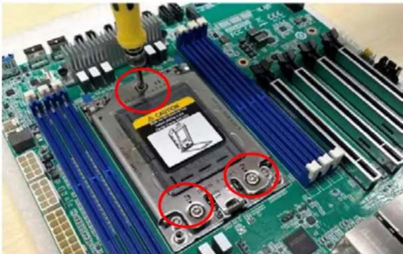
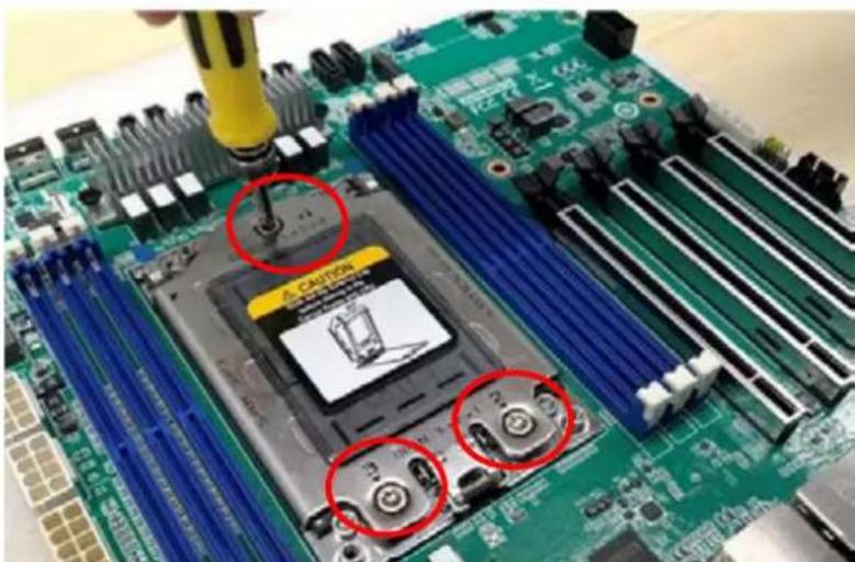
1.11 Processor Installation
The AIMB-592 is designed for AMD EPYC 7003 Series processors. Please follow the processor installation as below.
- Unscrew the three screws (shown above in red circles) on the top of the socket retention mechanism (SRM), then rotate the retention frame and rail frame (with external cap).
natural_image
Close-up of a green computer motherboard with blue CPU socket and screw slots, no visible text or symbols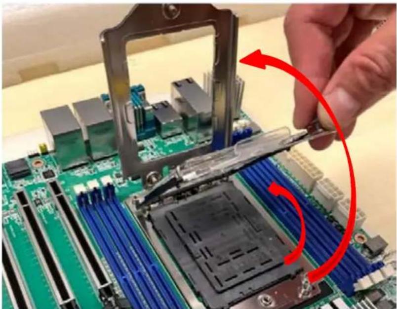
natural_image
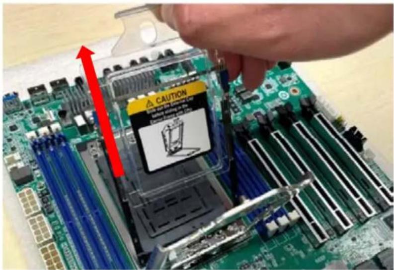
Close-up of a hand holding a CPU socket into a motherboard, with a red curved arrow indicating the process (no text or symbols visible)- Remove the external cap by pulling upwards.
text_image
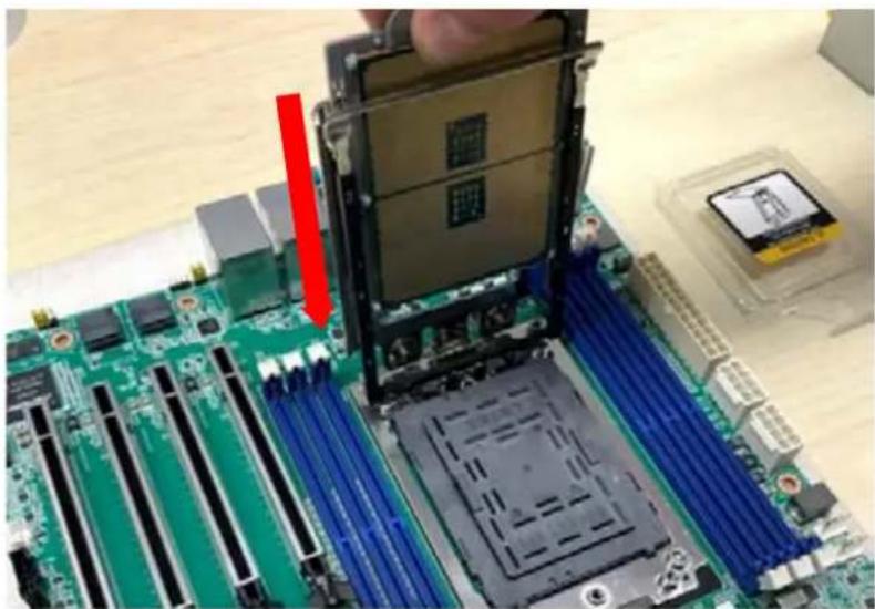
CAUTION Take out the computer Is coming from the computer Is coming from the computer Is coming from the computer- Install the carrier frame/CPU package to the rail frame, and then remove the PnP cover cap. Be very careful not to drop the PnP cover cap into the exposed contact field during the removal process.
natural_image
Close-up of a computer motherboard with a highlighted CPU socket and a red arrow indicating a component (no text or symbols visible)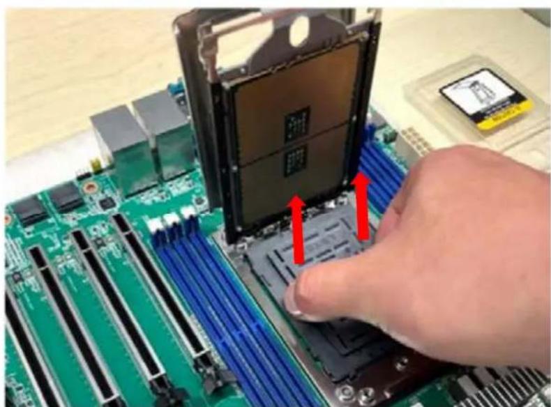
natural_image
Close-up of a hand pressing down on a green computer motherboard with a CPU socket and red arrows indicating motion (no text or symbols visible)- Rotate and push the rail frame and retention frame until they are in the horizontal position.

natural_image
Close-up of a green CPU motherboard with a red curved arrow pointing to a specific component, no visible text or symbols.
natural_image
Close-up of a green computer motherboard with CPU socket and blue heat sinks, hands adjusting the chip (no visible text or symbols)- Tighten the three screws (shown above in red circles) by using a T-20 screw-driver.
text_image
CAUTION 3.0 2.0 1.0- Install the processor heatsink module into the socket retention mechanism (SRM) by using a T-20 screwdriver (follow the heatsink label direction 1-2-3-4).

natural_image
Close-up of a green computer motherboard with visible CPU socket and cooling elements (no readable text or symbols)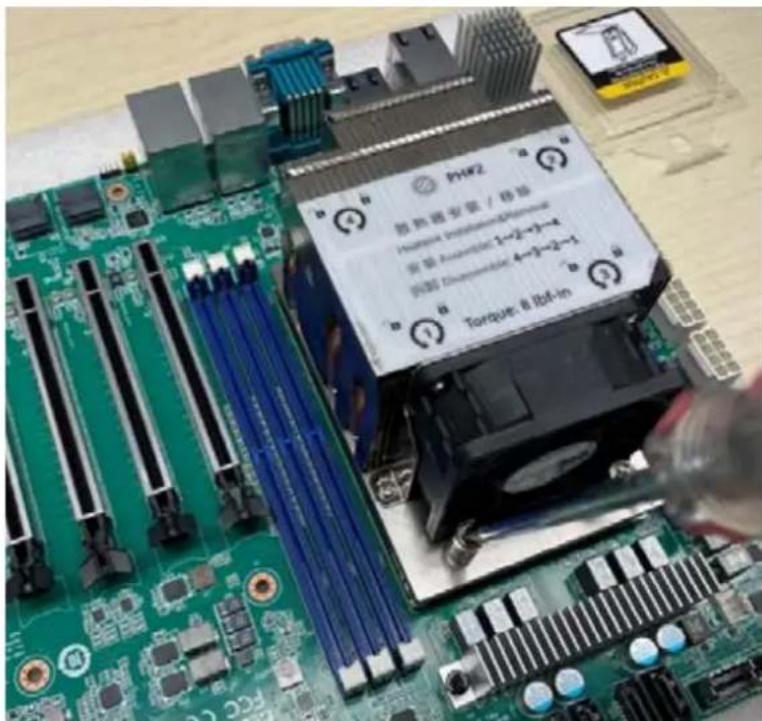
text_image
PHF2 防熱磁盤管 / 接場 Hormone Insulation&Perma 電極 Assembled: 1-2-3-4 電極 Thermocable: 4-3-2-1 Torque: 8 Bcf-inChapter 2
Connecting Peripherals
2.1 Introduction
You can access most of the connectors from the top of the board as it is being installed in the chassis. If you have a number of cards installed or have a packed chassis, you may need to partially remove the card to make all the connections.
2.2 LAN and USB Ports (LAN1\_USB12/ LAN2\_USB34/ LAN3\_4/LAN5)
The AIMB-592 provides up to five USB3.2 gen1 ports. (4 x USB ports on the rear side, 1 x USB port via the board pin header) The USB interface complies with USB Specification Rev 2.0 supporting transmission rates up to 480 Mbps and Rev 3.0 supporting transmission rate up to 5 Gbps. The USB interface can be disabled in the system BIOS setup.
The AIMB-592 is equipped with up to two 2.5G Mbps and two 10G Mbps Ethernet LAN adapters and one BMC LAN which are supported by all major network operating systems. The RJ-45 jacks on the rear panel provides convenient LAN connection.

text_image
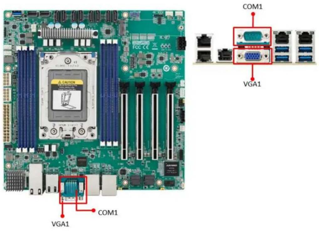
LAN3_4 LAN5 LAN1_USB12 LAN2_USB34 LAN2_USB12 LAN2_USB34 LAN3_4 LAN5 LAN1_USB12 LAN2_USB342.3 VGA and Serial Ports (VGA1/COM1)
AIMB-592 includes VGA1 interfaces that can drive conventional VGA1 displays. The serial port supports RS-232 and can connect to serial devices, such as a mouse or a printer, or to a communications network.
text_image
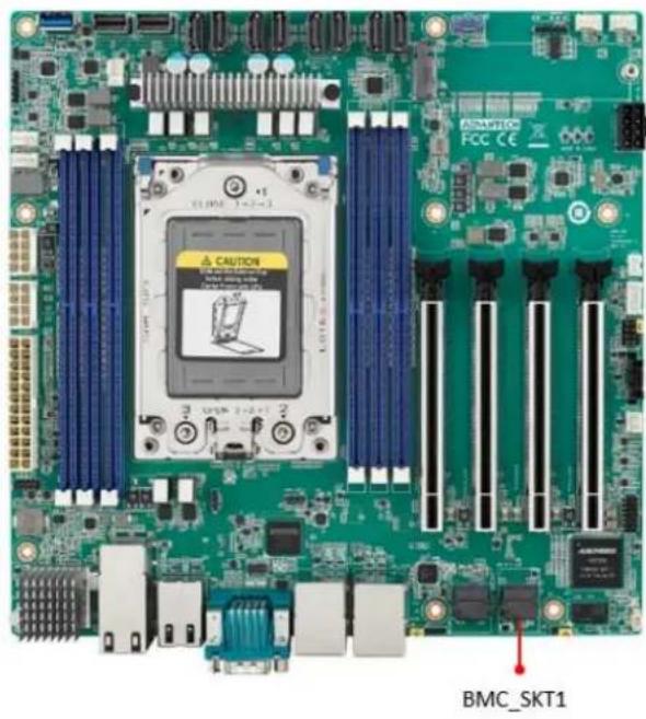
COM1 VGA1 VGA1 COM1 VGA12.4 BMC ROM socket (BMC\_SKT1)
natural_image
Green computer motherboard with visible CPU socket and ventilation slots (no readable text or symbols)2.5 BIOS SPI ROM socket (BIOS\_SKT1)
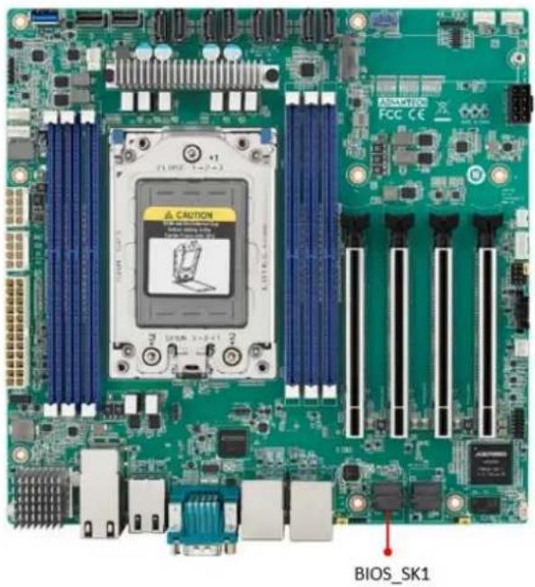
text_image
BIOS_SK12.6 Battery Holder (BAT1)
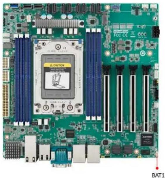
natural_image
Green computer motherboard with visible slots, CPU socket, and ventilation slots (no readable text or symbols)
text_image
+V3.3_SB R4203 0 Jumper_1/16W 0402 RDN_RTC_V3.3_SB C2534 NL/10uF 20k_10V C402 GND BAT1 4 3 2 1 R4212_10K 0402 1k_1/16W D140 BAS40-05 3 0.2A GOT-23 +VBAT GND WB_2V_S1.25mm| Pin | Signal |
| 1 | +VBAT |
| 2 | +VBAT |
| 3 | GND |
| 4 | GND |
2.7 LPC Connector (LPC1)
AIMB-592 has one LPC connector which is for BIOS usage.
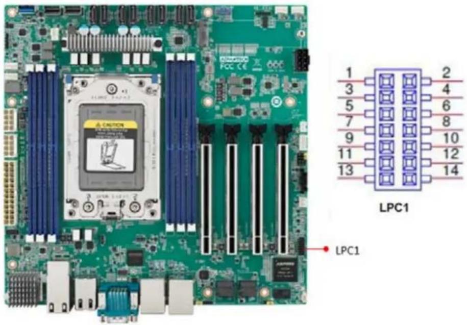
text_image
LPC1 LPC12.8 PCIe Expansion Slot (PCIEX16\_SLOT1/PCIEX16\_SLOT2/PCIEX16\_SLOT3/PCIEX16\_SLOT4)
AIMB-592 provides four PCIe x16 slots that can support up to two double-deck cards.
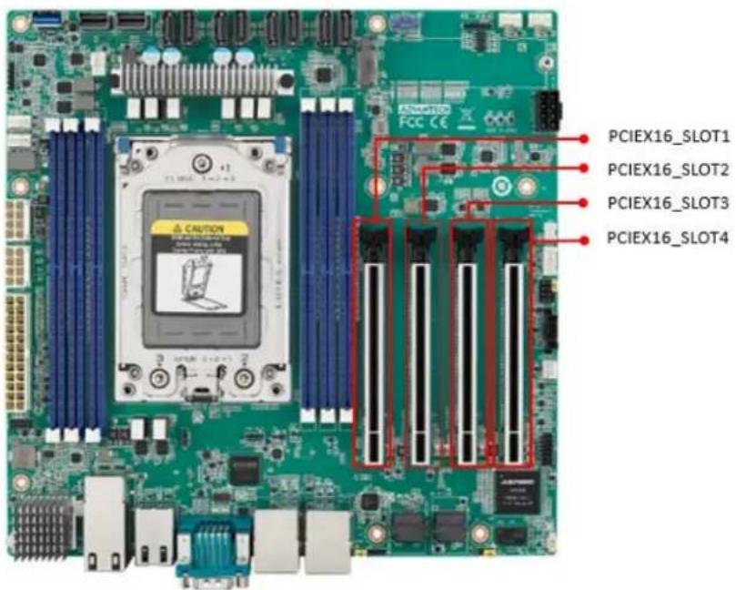
text_image
PCIEX16_SLOT1 PCIEX16_SLOT2 PCIEX16_SLOT3 PCIEX16_SLOT4Note!

- 16_SLOT4, There will be institutional interference with the connectors at LPC1, SYS_LED1, JFP1+JFP2, JFP3, SMBUS1, SLOT12V1, PMBUS1, SYSFAN3, SYSFAN4. The actual situation still needs to be based on the length of the graphic card.
- Under POST, only BMC VGA output is supported, and external graphics cards on PCIe Slot must be installed the driver, then it can display normally under the OS.
- Depending on the fan used, if install the graphic card on the PCIEX16_SLOT1, should remove it as follows steps.
- When using with STD Cooler (1970004817N001): Remove the memory inserted in the DIMMC1 position before removing the graphics card.
- When using with Customized VC Heatsink: Remove this fan, uninstall the memory at DIMMC1 before removing the graphics card.
- If users would insert an Add-on card, it is recommended to use the Add-on card with PCIe Gen4.
2.9 System Error LED wafer (BMC\_SYSLED1)
System Error LED wafer is for usage of identify the chassis location by "ipmitool chassis identify" command.
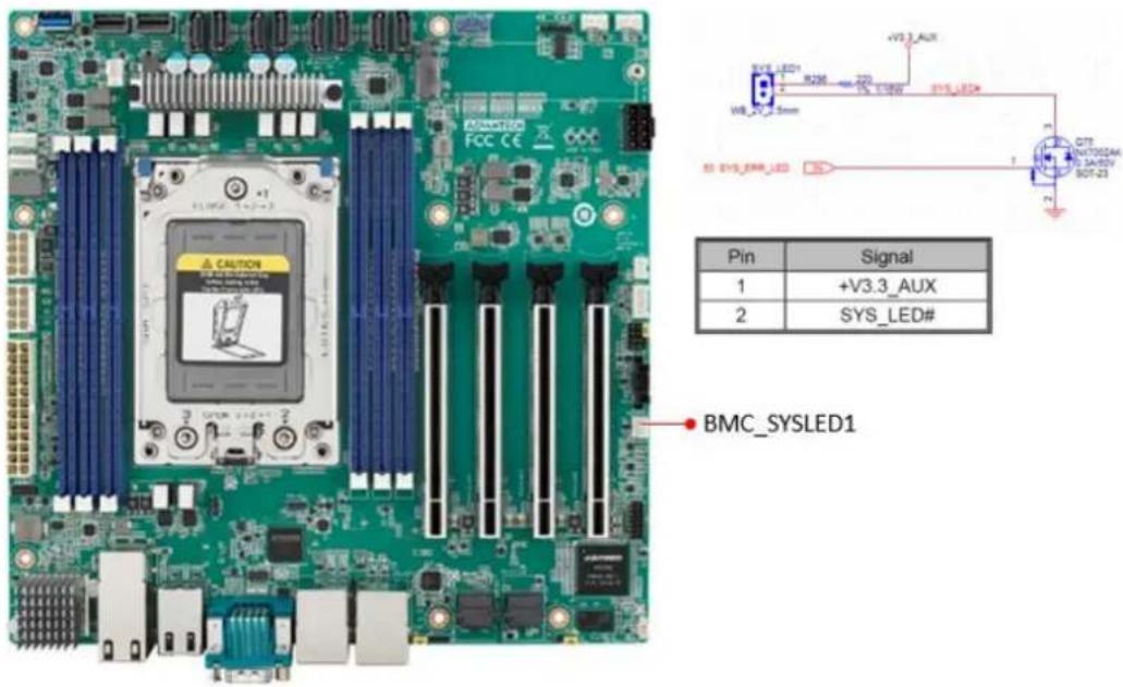
text_image
BMC_SYSLED1 Pin Signal 1 +V3.3_AUX 2 SYS_LED#2.10 PMBus wafer (PMBUS1)
PMBUS connector is for communicating with power supply that has PMBUS function supported.

text_image
PMBUS CONN. Pin Signal 1 PMBUS_SMB_CLK 2 PMBUS_SMB_DATA 3 PMBUS_SW_ALERT# 4 GND 5 +V3.3_AUX2.11 Hardware SMBUS (SMBUS1)
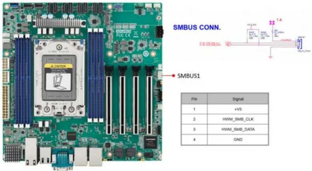
text_image
SMBUS CONN. SMBUS1 Pin | Signal | 1 | +V5 2 | HWM_SMB_CLK 3 | HWM_SMB_DATA 4 | GND2.12 Front Panel3 (JFP3)

text_image
+V5_SB R290 220 PWRLED JFP3 0402 5%_1/16W FP_PWR_BTN_S# WB_3V_2.0mm JFP3 Pin Signal 1 FP_PWR_BTN_S# 2 GND 3 +V5_SB2.13 Graphics Card 12V slot (PCIE\_SLOT12V1)
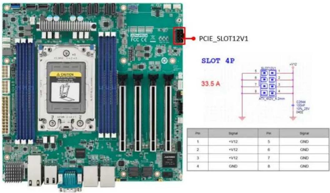
text_image
PCIe_SLOT12V1 SLOT 4P 33.5 A 5 SLOT12V1 6 1 7 2 8 3 AT1_412V_4.2mm +V12 C2844 100nF 125_25V 0402 Pin Signal Pin Signal 1 +V12 5 GND 2 +V12 6 GND 3 +V12 7 GND 4 GND 8 GNDNote! This connector is only necessary if PCIe cards that draw more than 70 watts from the PCIe bus are fully-installed on four slots on the motherboard and it is only for power input usage.
2.14 System FAN Connector (SYSFAN1/SYSFAN2/SYSFAN3/SYSFAN4)
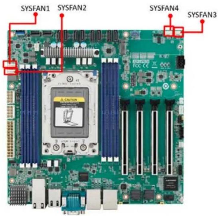
text_image
SYSFAN1 SYSFAN2 SYSFAN4 SYSFAN3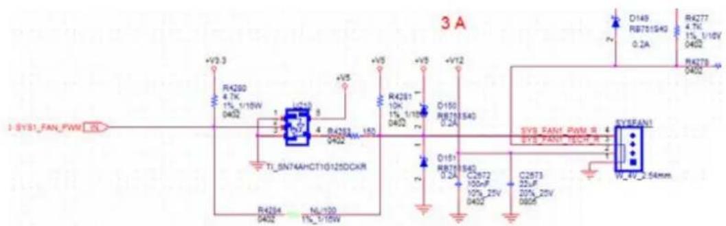
text_image
3 A 1 SYS1_FAN_PWM +V2.3 R4280 4.7K 1%_1/15W 0402 R4281 10K 1%_1/15W 0402 D150 RB75640 0.2A +V5 +V5 +V12 R4277 4.7K 1%_1/15W 0402 R4278 0402 T1_SN74AHCT10125DCKR R4284 0402 N0_100 1%_1/15W SYS_PAN1_PWM_R SYS_PAN1_INCH_R SYS_PAN1 W_4V_2.54mm| Pin | Signal |
| 1 | GND |
| 2 | +V12 |
| 3 | SYS1_FAN_TACH |
| 4 | SYS_FAN1_PWM |

text_image
SYS2_FAN_PWM IN +V3.3 R4293 4.7K 1% 1/16W 0402 U24 5 R4296 4 0402 SN74AHCT1G125DCKR| Pin | Signal |
| 1 | GND |
| 2 | +V12 |
| 3 | SYS2_FAN_TACH |
| 4 | SYS2_FAN_PWM |

text_image
SYS3 FAN_PWMOUT R951 0 0402 5% SYS3 FAN_PWMOUT_R 4 SYS3 FAN_SPEED 3 SYS3 FAN_OUT 2 C804 C805 10uF 100nF 16V 10%_16V 0805 W_4V_2.54mm| Pin | Signal |
| 1 | GND |
| 2 | SYS3_FAN_OUT |
| 3 | SYS3_FAN_SPEED |
| 4 | SYS3_FAN_PWMOUT |
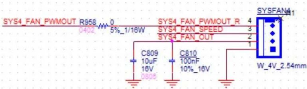
text_image
SYS4_FAN_PWMOUT R958 0 0402 W 5%_1/16W SYS4_FAN_PWMOUT_R 4 SYS4_FAN_SPEED 3 SYS4_FAN_OUT 2 C809 C810 10uF 100nF 16V 10%_16V 0805 W_4V_2.54mm| Pin | Signal |
| 1 | GND |
| 2 | SYS4_FAN_OUT |
| 3 | SYS4_FAN_SPEED |
| 4 | SYS4_FAN_PWMOUT |
2.15 Serial General Purpose I/O Connector (SGPIO1)

natural_image
Green computer motherboard with CPU socket and visible slots, no readable text or symbols on the board itself
text_image
R_SGPIO2_CLK_BUF1 1 SGPIO1 R_SGPIO2_LOAD_BUF1 3 4 R_SGPIO2_DATAOUT_BUF1 8 PH_5x1V_2.54mm| Pin | Signal |
| 1 | R_SGPIO_CLK_BUF1 |
| 2 | |
| 3 | R_SGPIO_LOAD_BUF1 |
| 4 | R_SGPIO_DATAOUT_BUF1 |
| 5 |
2.16 Serial ATA Interface Connector (SATA1\~8)
AIMB-592 features eight serial ATA III interfaces (up to 600 MB/s) and eases cabling to hard drives with long and space-saving cables.
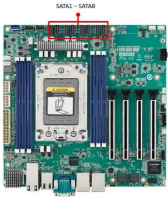
text_image
SATA1 - SATA82.17 CPU Fan Connector (CPUFAN1)
If a fan is used, this connector supports cooling fans that draw up to 2A (24W).
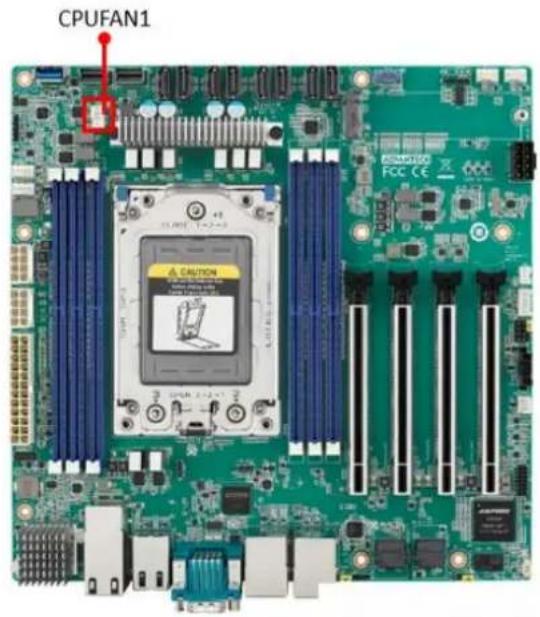
text_image
CPUFAN1| Pin | Signal |
| 1 | GND |
| 2 | +V12_8P_0 |
| 3 | EC_FANTACH0 |
| 4 | EC_CPU_PWM |
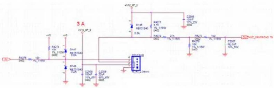
text_image
3 A +V12 SP_5 D140 RB71540 0.3A R4271 4.7V 1% L/18W 0402 R4272 1% L/18W 0402 R4273 10K 1% L/18W 0402 C26M7 N0.1nF 10% 8kV +V12 SP_5 D140 RB71540 0.2A R4271 4.7V 1% L/18W 0402 R4273 10K 1% L/18W 0402 C26M7 N0.1nF 10% 8kV +V12 SP_5 D140 RB71540 0.2A R4271 4.7V 1% L/19W 0402 R4273 10K 1% L/19W 0402 C26M7 N0.1nF 10% 8kV2.18 NGFF M.2 M-Key (NGFF\_M1)
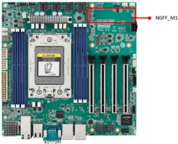
text_image
NGFF_M1 RAMS FCC CEM.2 M-key: 2280, support SATA III or PCIex4 interface, and can support NVMe devices.
2.19 Slimline SAS 4i Connector (SAS1/SAS2)
This connector has PCIE Gen 4 signal.
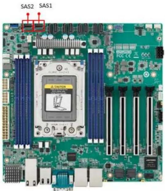
text_image
SAS2 SAS1 ADDITION FCC CE2.20 General purpose I/O Connector (GPIO1)
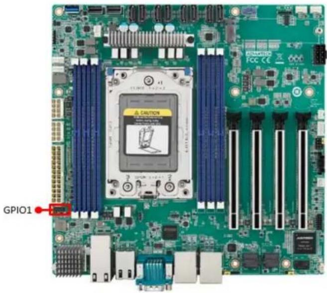
text_image
GPIO1 CAUTION FCC CE2.21 USB3.2 Gen1 vertical connector (USB5)
The USB port complies with USB 3.2 Gen1. Transmission rates of up to 5Gbps. Fuse protection is supported.

natural_image
Green computer motherboard with CPU socket and ventilation slots (no readable text or symbols)2.22 DDR4 RDIMM slot (DIMME1/ DIMMH1/ DIMMG1/ DIMMA1/ DIMMD1/ DIMMC1)
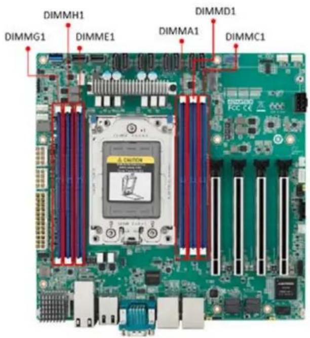
text_image
DIMMH1 DIMMG1 DIMME1 DIMMD1 DIMMA1 DIMMC12.23 ATX Power Connector (ATX12V1/ ATX12V2/ ATXPWR1)
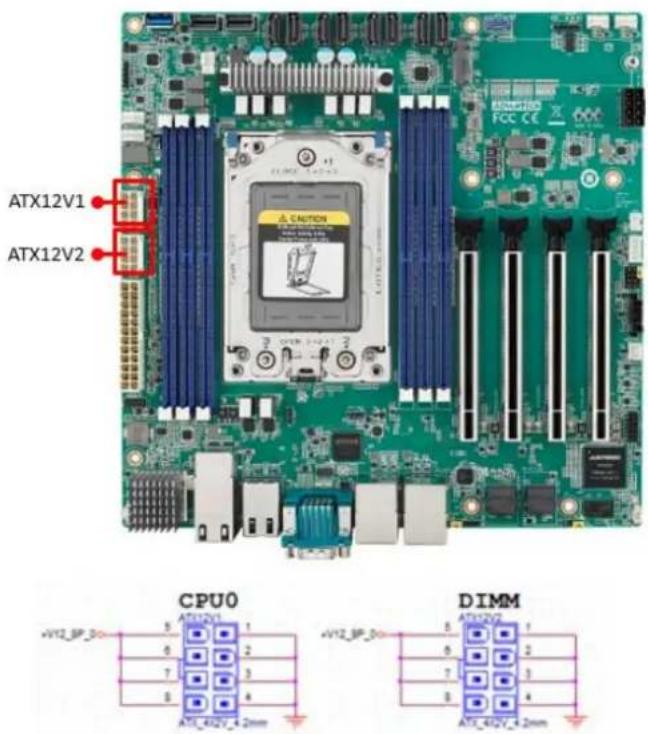
text_image
ATX12V1 ATX12V2 CPU0 DIMM| Pin | Signal | Pin | Signal |
| 1 | GND | 5 | +V12_8P_0 |
| 2 | GND | 6 | +V12_8P_0 |
| 3 | GND | 7 | +V12_8P_0 |
| 4 | GND | 8 | +V12_8P_0 |

text_image
ATXPWR1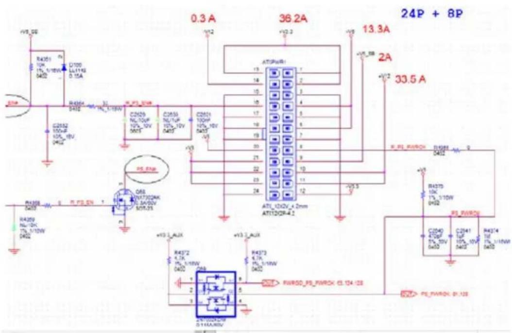
text_image
0.3 A 36.2A 13.3A 24P + 8P 13.3A 33.5 A R4301 10k 15_1/10W 0402 D100 LL111K 0.15A R4304 32 IN_1-10W C2502 100pF 10k_10V 0402 C2503 NL10pF 10k_10V 0402 C2504 NL1/TuF 10k_10V 0402 C2505 100pF 10k_10V 0402 C2506 100pF 10k_10V 0402 C2507 100pF 10k_10V 0402 C2508 100pF 10k_10V 0402 C2509 NL1/20k 17k_1/10W 0402 C2510 RL_PWRCH R4375 10k 17k_1/10W 0402 R4376 470pF 57k_20V 0402 C2541 1uF 10p_10V 0402 R4374 1uF 17k_1/10W 0402 C2542 RL_PWRCH_61.128| Pin | Signal Pin Definition | Pin | Signal Pin Definition |
| 1 | +V3.3 | 13 | +V3.3 |
| 2 | +V3.3 | 14 | -V12 |
| 3 | GND | 15 | GND |
| 4 | +V5 | 16 | PS_ON= |
| 5 | GND | 17 | GND |
| 6 | +V5 | 18 | GND |
| 7 | GND | 19 | GND |
| 8 | PWR_OK | 20 | -V5 |
| 9 | +V5_SB | 21 | +V5 |
| 10 | +V12 | 22 | +V5 |
| 11 | +V12 | 23 | +V5 |
| 12 | +V3.3 | 24 | GND |
This connector is for an ATX Micro-Fit power supply. The plugs from the power supply are designed to fit these connectors from only one direction. Determine the proper orientation and push down firmly until the connectors join completely.
Note!

- Please connect the ATX12V1 and ATX12V2 connector with the PSU ATX 12V 8-pin connector, otherwise AIMB-592 will not boot up normally.
- For a fully configured system, we recommend that you use a power supply unit (PSU) that complies with ATX 12 V Specification 2.0 (or later version) and minimum output should be at least 700W.
Chapter 3
BIOS and BMC Operation
3.1 Introduction
AMI BIOS has been integrated into many motherboards, and has been very popular for over a decade. With the AMI BIOS Setup program, you can modify BIOS settings to control the special features of your computer. The Setup program uses a number of menus for making changes. This chapter describes the basic navigation of the AIMB-592 setup screens.
3.2 BIOS Setup
The AIMB-592 Series system has AMI BIOS built in, with a SETUP utility that allows users to configure required settings or to activate certain system features.
The SETUP saves the configuration in the FLASH of the motherboard. When the power is turned off, the battery on the board supplies the necessary power to preserve the FLASH.
When the power is turned on, press the or
| Control Keys |
| < ← >> < → > Select Screen |
| < ↑ >> < ↓ > Select Item |
| <+/-> Change Opt |
| < F1> General help |
| < F2> Previous Values |
| < F3> Optimized Defaults |
| < F4> Save & Exit |
| < Esc> Exit |
3.2.1 Main Menu
Press to enter AMI BIOS CMOS Setup Utility, the Main Menu will appear on the screen. Use arrow keys to select among the items and press
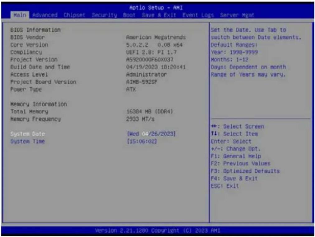
text_image
Aptio Setup - AMI Main Advanced Chipset Security Boot Save & Exit Event Logs Server Mgmt BIOS Information BIOS Vendor American Megatrends Core Version 5.0.2.2 0.08 x64 Compliancy UEFI 2.8: PI 1.7 Project Version A5920000F60x037 Build Date and Time 04/19/2023 18:20:41 Access Level Administrator Project Board Version AIMB-592SF Power Type ATX Memory Information Total Memory 16384 MB (DDR4) Memory Frequency 2933 MT/s System Date [Wed 04/26/2023] System Time [15:06:02] Set the Date. Use Tab to switch between Date elements. Default Ranges: Year: 1998-9999 Months: 1-12 Days: Dependent on month Range of Years may vary. ++: Select Screen T1: Select Item Enter: Select +/-: Change Opt. F1: General Help F2: Previous Values F3: Optimized Defaults F4: Save & Exit ESC: Exit Version 2.21.1280 Copyright (C) 2023 AMIThe Main BIOS setup screen has two main frames. The left frame displays all the options that can be configured. Grayed-out options cannot be configured; options in blue can. The right frame displays the key legend.
Above the key legend is an area reserved for a text message. When an option is selected in the left frame, it is highlighted in white. Often a text message will accompany it.
■ System Time/System Date
Use this option to change the system time and date. Highlight the System Time or System Date using the
3.2.2 Advanced BIOS Features
Select the Advanced tab from the AIMB-592 setup screen to enter the Advanced BIOS Setup screen. You can select any of the items in the left frame of the screen, such as CPU Configuration, to go to the sub menu for that item. You can display an Advanced BIOS Setup option by highlighting it using the

text_image
Aptio Setup - AMI Main Advanced Chipset Security Boot Save & Exit Event Logs Server Mgmt Trusted Computing AMD CBS EIO-201 EC Configuration SS RTC Wake Settings Serial Port Console Redirection CPU Configuration USB Configuration Network Stack Configuration CSM Configuration NVMe Configuration SATA Configuration Tls Auth Configuration Driver Health Trusted Computing Settings +: Select Screen T1: Select Item Enter: Select +/-: Change Opt. F1: General Help F2: Previous Values F3: Optimized Defaults F4: Save & Exit ESC: Exit Version 2.21.1280 Copyright (C) 2023 AMI
text_image
Aotio Setup - AMI Advanced TPM 2.0 Device Found Firmware Version: 7.2 Vendor: NTC Security Device Support [Enable] Active PCR banks SHA-1,SHA256 Available PCR banks SHA-1,SHA256,SHA384 SHA-1 PCR Bank [Enabled] SHA256 PCR Bank [Enabled] SHA384 PCR Bank [Disabled] Pending operation [None] Platform Hierarchy [Enabled] Storage Hierarchy [Enabled] Endorsement Hierarchy [Enabled] TPM 2.0 UEFI Spec Version [TCB_2] Physical Presence Spec Version [1.3] TPM 2.0 InterfaceType [TIS] Device Select [Auto] Enables or Disables BIOS support for security device. 0.S. will not show Security Device. TCB EFI protocol and INT1A interface will not be available. ++: Select Screen T1: Select Item Enter: Select +/-: Change Opt. F1: General Help F2: Previous Values F3: Optimized Defaults F4: Save & Exit ESC: Exit Version 2.21.1280 Copyright (C) 2023 AMI3.2.2.1 AMD CBS

text_image
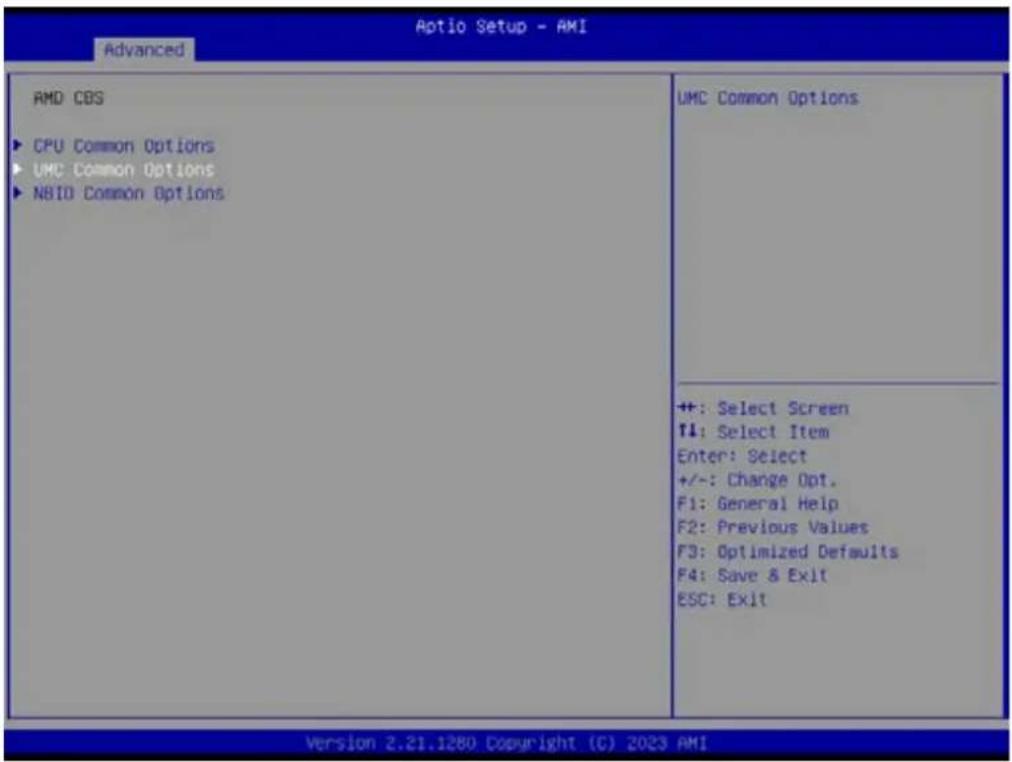
Aptio Setup - AMI Main Advanced Chipset Security Boot Save & Exit Event Logs Server Xgmt ► Trusted Computing ► AMD CBS ► EIO-201 EC Configuration ► SS RTC Make Settings ► Serial Port Console Redirection ► CPU Configuration ► USB Configuration ► Network Stack Configuration ► CSM Configuration ► NVMe Configuration ► SATA Configuration ► Tls Auth Configuration ► Driver Health AMD CBS Setup Page ++ +: Select Screen T1: Select Item Enter: Select +/-: Change Opt. F1: General Help F2: Previous Values F3: Optimized Defaults F4: Save & Exit ESC: Exit Version 2.21.1280 Copyright (C) 2023 AMIAMD CBS Setup Page

text_image
Aptio Setup - AMI Advanced AMD CBS ► CPU Common Options ► UMC Common Options ► NBIO Common Options CPU Common Options ++ +: Select Screen ↑: Select Item Enter: Select +/-: Change Opt. F1: General Help F2: Previous Values F3: Optimized Defaults F4: Save & Exit ESC: Exit Version 2.22.1282 Copyright (C) 2022 AMICPU Common Options - Performance

text_image
Optio Setup - AMI Advanced CPU Common Options Performance Platform First Error Handling [Auto] Core Performance Boost [Auto] Global C-state Control [Auto] Performance ++: Select Screen T1: Select Item Enter: Select +/-: Change Opt. F1: General Help F2: Previous Values F3: Optimized Defaults F4: Save & Exit ESC: Exit Version 2.21.1280 Copyright (C) 2023 AMI■ Platform First Error Handling [Auto]
■ Core Performance Boost [Auto]
Global C-state Control [Auto]

text_image
Optio Setup - AMI Advanced Performance OC Mode [Normal Operation] ► Custom Core Pstates ► CCD/Core/Thread Enablement SMT Control [Auto] Can be used to modify the number of core/CCD. ++ : Select Screen ↑1: Select Item Enter: Select +/-: Change Opt. F1: General Help F2: Previous Values F3: Optimized Defaults F4: Save & Exit ESC: Exit Version 2.21.1280 Copyright (C) 2023 AMI- OC Mode [Normal Operation] Can be used to modify the number of core/CCD. Custom Core P-states
CCD/Core/Thread Enablement
■ SMT Control [Auto]
text_image
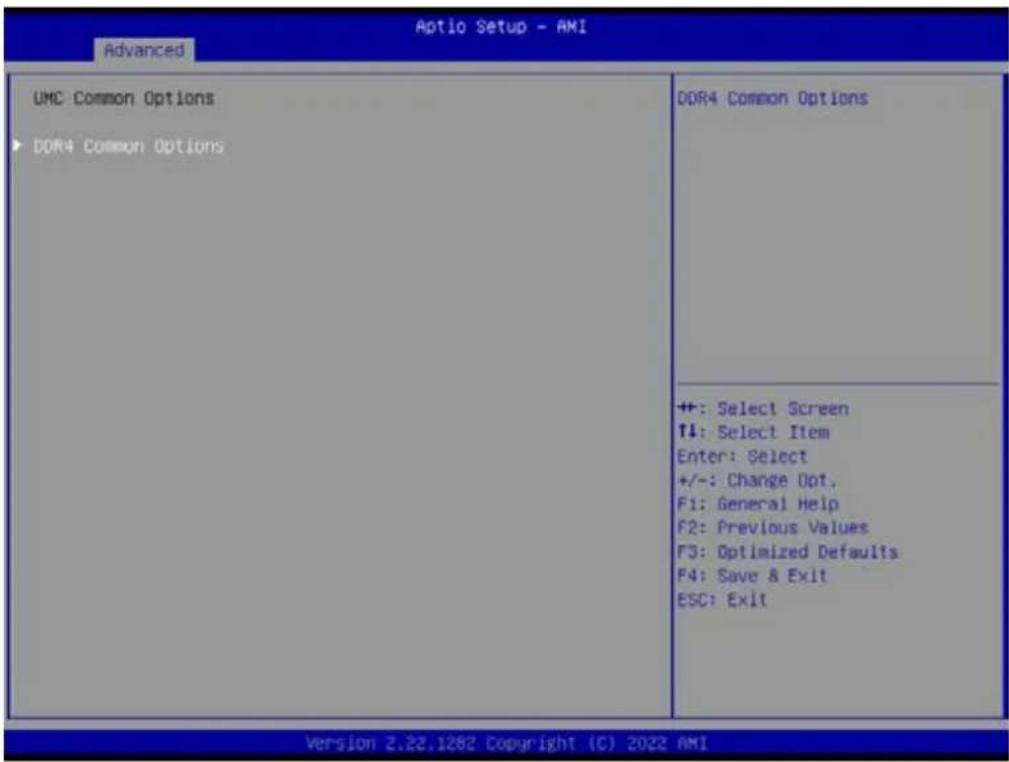
Aptio Setup - AMI Advanced AMD CBS ► CPU Common Options ► UMC Common Options ► NBIO Common Options UMC Common Options ++ : Select Screen F1: Select Item Enter: Select +/-: Change Opt. F1: General Help F2: Previous Values F3: Optimized Defaults F4: Save & Exit ESC: Exit Version 2.21.1280 Copyright (C) 2023 AMIUMC Common Options - DDR4 Common Options
text_image
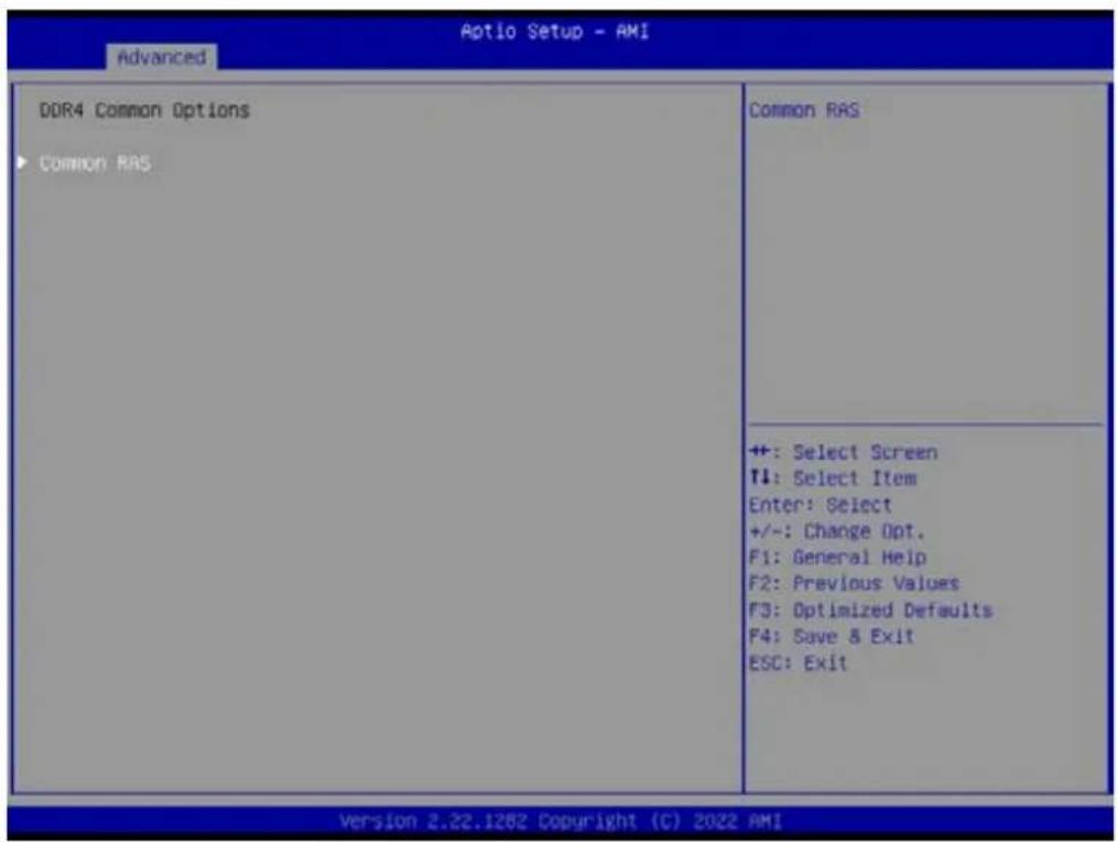
Aptio Setup - AMI Advanced UMC Common Options ▶ DDR4 Common Options DDR4 Common Options ++: Select Screen ↑↓: Select Item Enter: Select +/-: Change Opt. F1: General Help F2: Previous Values F3: Optimized Defaults F4: Save & Exit ESC: Exit Version 2.22.1282 Copyright (C) 2022 AMIDDR4 Common Options - Common RAS
text_image
Aotio Setup - AMI Advanced DDR4 Common Options ▶ Common RAS Common RAS ++: Select Screen T1: Select Item Enter: Select +/-: Change Opt. F1: General Help F2: Previous Values F3: Optimized Defaults F4: Save & Exit ESC: Exit Version 2.22.1282 Copyright (C) 2022 AMIDDR4 Common Options - Common RAS - ECC Configuration

text_image
Aptio Setup - AMI Advanced ECC Configuration DRAM ECC Symbol Size [Auto] DRAM ECC Enable [Auto] DRAM UECC Retry [Auto] DRAM ECC Symbol Size (x4/xx8/xx16) - UMC_DM::EccCtrl1[EccSymbolSize16 , EccSymbolSize] ++: Select Screen ↑↓: Select Item Enter: Select +/-: Change Opt. F1: General Help F2: Previous Values F3: Optimized Defaults F4: Save & Exit ESC: Exit Version 2.21.1280 Copyright (C) 2023 AMI- DRAM ECC Symbol Size [Auto]
- DRAM ECC Enable [Auto]
- DRAM UECC Retry [Auto]
text_image
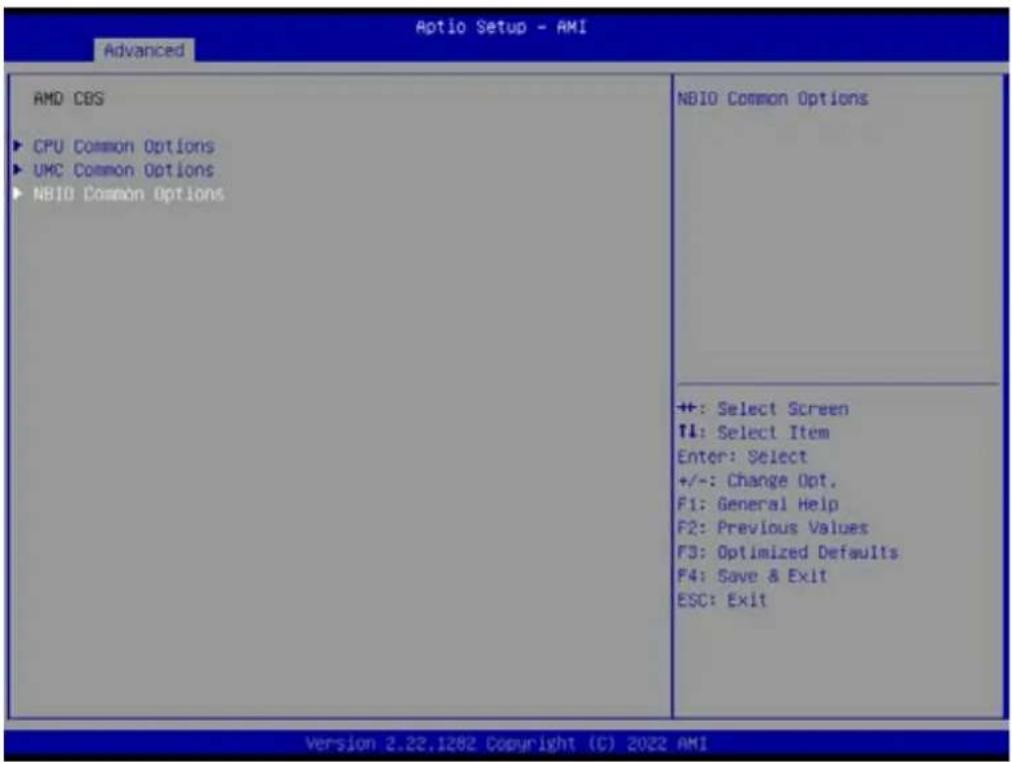
Aptio Setup - AMI Advanced AMD CBS ► CPU Common Options ► UMC Common Options ► NBI0 Common Options NBIO Common Options ++: Select Screen T4: Select Item Enter: Select +/-: Change Opt. F1: General Help F2: Previous Values F3: Optimized Defaults F4: Save & Exit ESC: Exit Version 2.22.1282 Copyright (C) 2022 AMINBIO Common Options
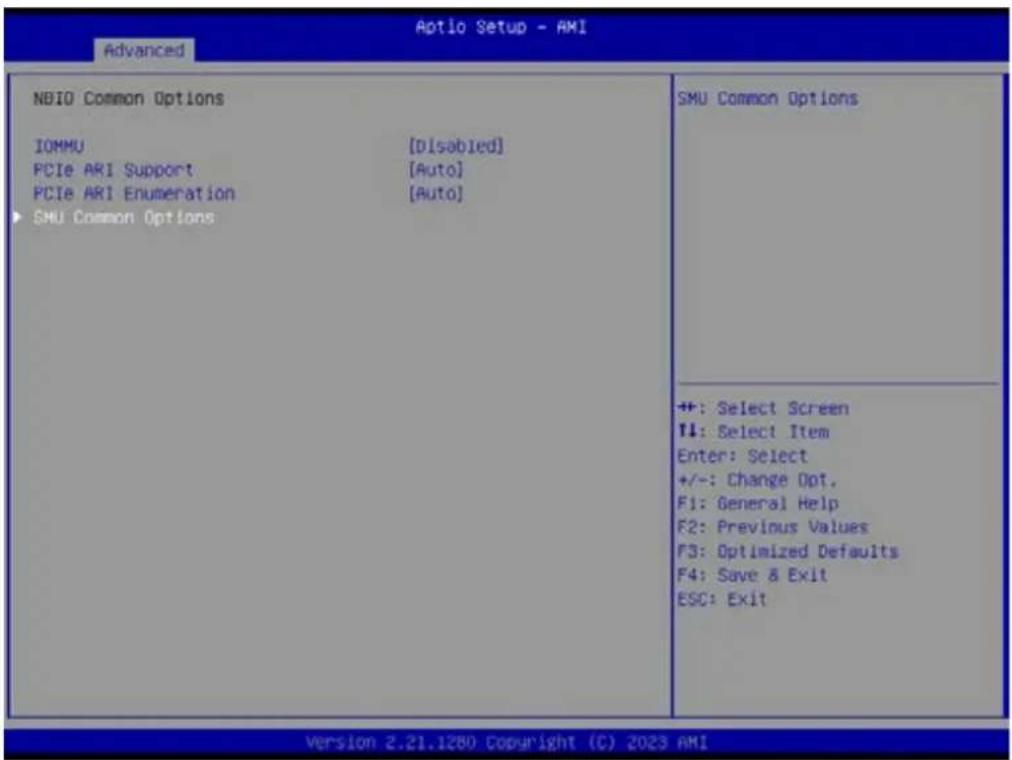
text_image
Aptio Setup - AMI Advanced NBIO Common Options IOMMU [Disabled] PCIe ARI Support [Auto] PCIe ARI Enumeration [Auto] SMU Common Options SMU Common Options ++: Select Screen 11: Select Item Enter: Select +/-: Change Opt. F1: General Help F2: Previous Values F3: Optimized Defaults F4: Save & Exit ESC: Exit Version 2.21.1280 Copyright (C) 2023 AMIIOMMU [Disabled]
PCIe ARI Support [Auto]
■ PCIe ARI Enumeration [Auto]
■ SMU Common Options
SMU Common Options
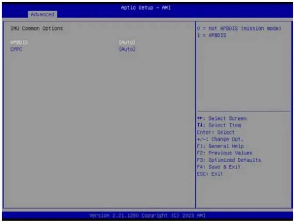
text_image
Optio Setup - AMI Advanced SMU Common Options APBDIS [Auto] CPPC [Auto] 0 = not APBDIS (mission mode) 1 = APBDIS ++: Select Screen T4: Select Item Enter: Select +/-: Change Opt. F1: General Help F2: Previous Values F3: Optimized Defaults F4: Save & Exit ESC: Exit Version 2.21.1280 Copyright (C) 2023 AMIAPBDIS [Auto]
CPPC [Auto]
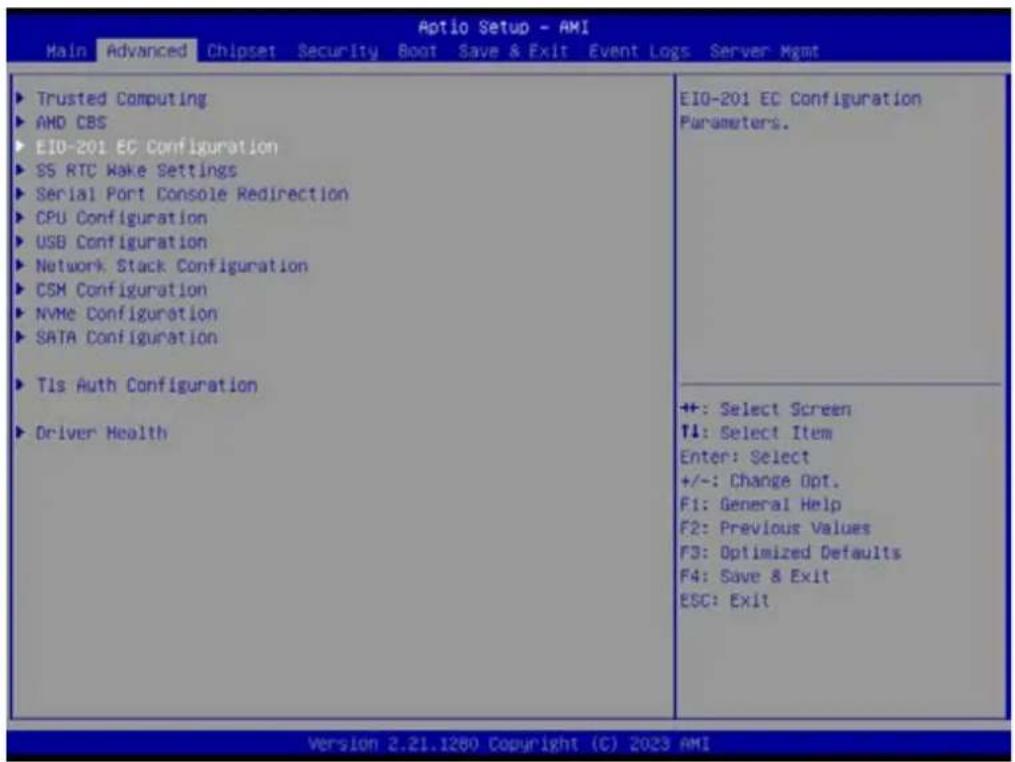
3.2.2.2 EIO-201 EC Configuration
text_image
Aptio Setup - AMI Main Advanced Chipset Security Boot Save & Exit Event Logs Server Mgmt ► Trusted Computing ► AMD CBS ► EIO-201 EC Configuration ► SS RTC Wake Settings ► Serial Port Console Redirection ► CPU Configuration ► USB Configuration ► Network Stack Configuration ► CSM Configuration ► NVMe Configuration ► SATA Configuration ► Tls Auth Configuration ► Driver Health EIO-201 EC Configuration Parameters. ++: Select Screen ↑1: Select Item Enter: Select +/-: Change Opt. F1: General Help F2: Previous Values F3: Optimized Defaults F4: Save & Exit ESC: Exit Version 2.21.1280 Copyright (C) 2023 AMI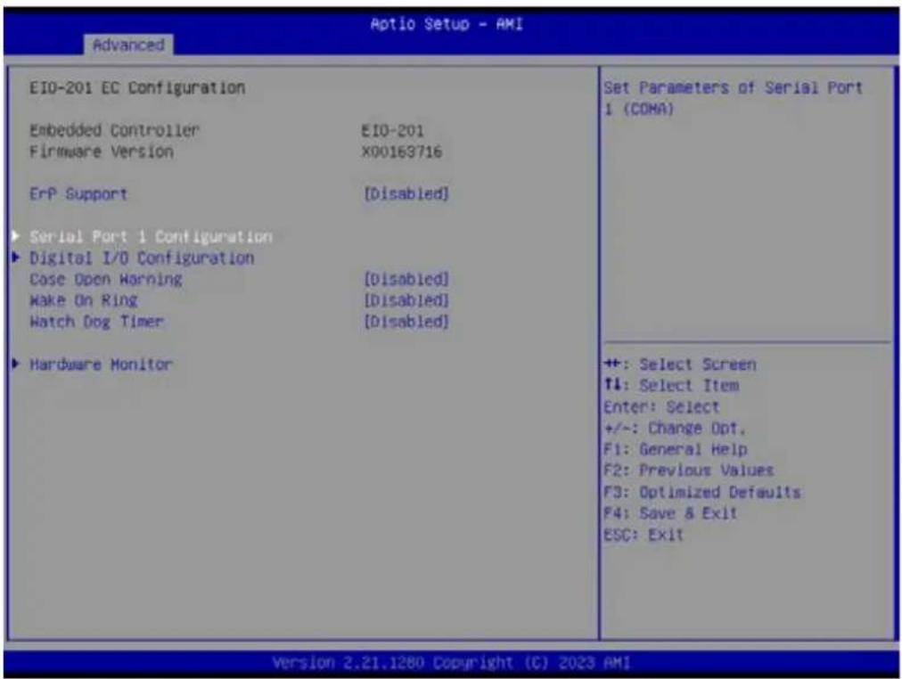
text_image
EIO-201 EC Configuration Embedded Controller EIO-201 Firmware Version X00163716 ErP Support [Disabled] ► Serial Port 1 Configuration ► Digital I/O Configuration Case Open Warning [Disabled] Make On Ring [Disabled] Watch Dog Timer [Disabled] ► Hardware Monitor Set Parameters of Serial Port 1 (COMA) ++ : Select Screen ↑4: Select Item Enter: Select +/-: Change Opt. F1: General Help F2: Previous Values F3: Optimized Defaults F4: Save & Exit ESC: Exit Version 2.21.1280 Copyright (C) 2023 AMISerial Port 1 Configuration Set Parameters of Serial Port1 (COMA)
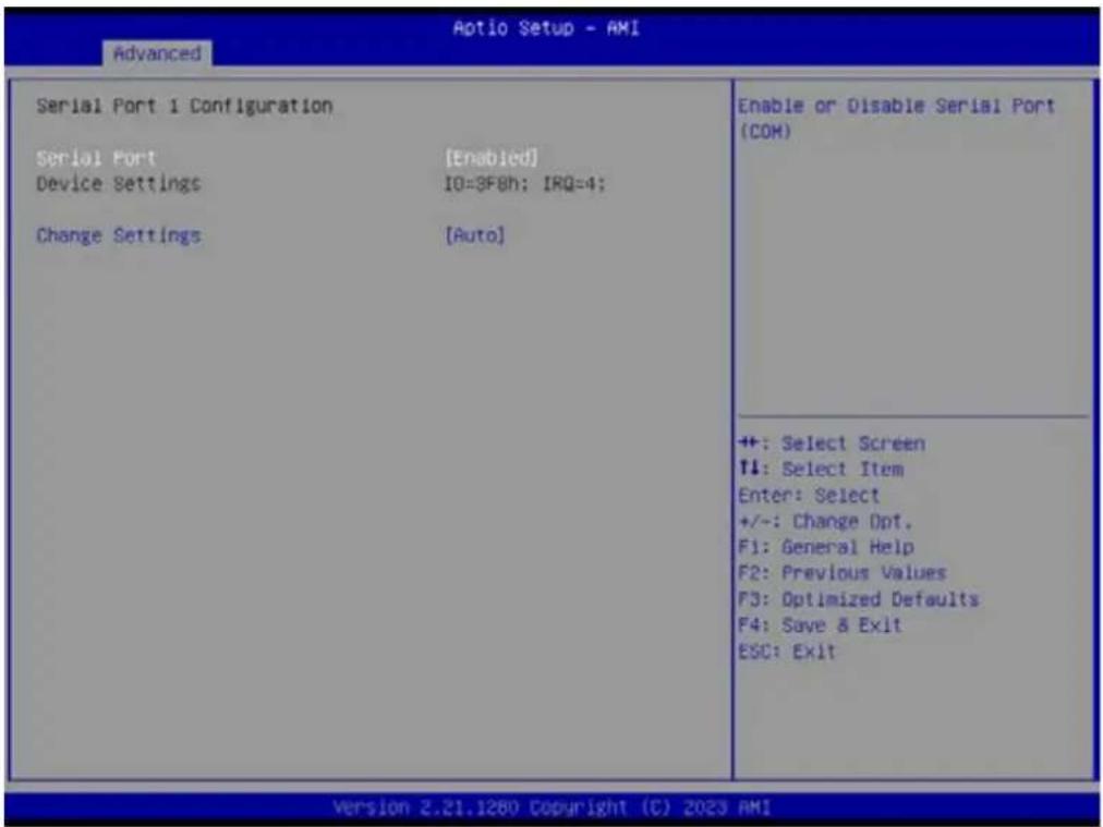
text_image
Aptio Setup - AMI Advanced Serial Port 1 Configuration Serial Port [Enabled] Device Settings IO=3F8h; IRQ=4; Change Settings [Auto] Enable or Disable Serial Port (COH) ++ : Select Screen ↑: Select Item Enter: Select +/-: Change Opt. F1: General Help F2: Previous Values F3: Optimized Defaults F4: Save & Exit ESC: Exit Version 2.21.1280 Copyright (C) 2023 AMI- Serial Port
Enable or Disable Serial Port (COM)
- Serial Port [Enable]
- Device Settings IO=3F8h; IRQ=4;
- Change Settings [Auto]
Serial Port 2 Configuration
Set Parameters of Serial Port2 (COMB)
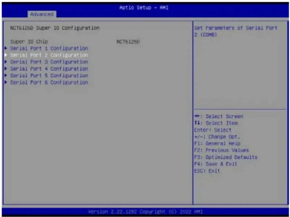
text_image
Aptio Setup - AMI Advanced NCT6126D Super IO Configuration Super IO Chip NCT6126D ► Serial Port 1 Configuration ► Serial Port 2 Configuration ► Serial Port 3 Configuration ► Serial Port 4 Configuration ► Serial Port 5 Configuration ► Serial Port 6 Configuration Set Parameters of Serial Port 2 (COMB) ++ : Select Screen ↑↓: Select Item Enter: Select +/-: Change Opt. F1: General Help F2: Previous Values F3: Optimized Defaults F4: Save & Exit ESC: Exit Version 2.22.1282 Copyright (C) 2022 AMI]
- Serial Port
Enable or Disable Serial Port (COM)

text_image
Advanced Serial Port 2 Configuration Serial Port [Enabled] Device Settings IO=2F8h; IRQ=3; Change Settings [Auto] Device Mode (RS232) Enable or Disable Serial Port (COM) ++ : Select Screen T1: Select Item Enter: Select +/-: Change Opt. F1: General Help F2: Previous Values F3: Optimized Defaults F4: Save & Exit ESC: Exit Version 2.22.1282 Copyright (C) 2022 AMI- Serial Port [Enable]
- Device Settings IO=2F8h; IRQ=3;
- Change Settings [Auto]
- Device Mode [RS232]

text_image
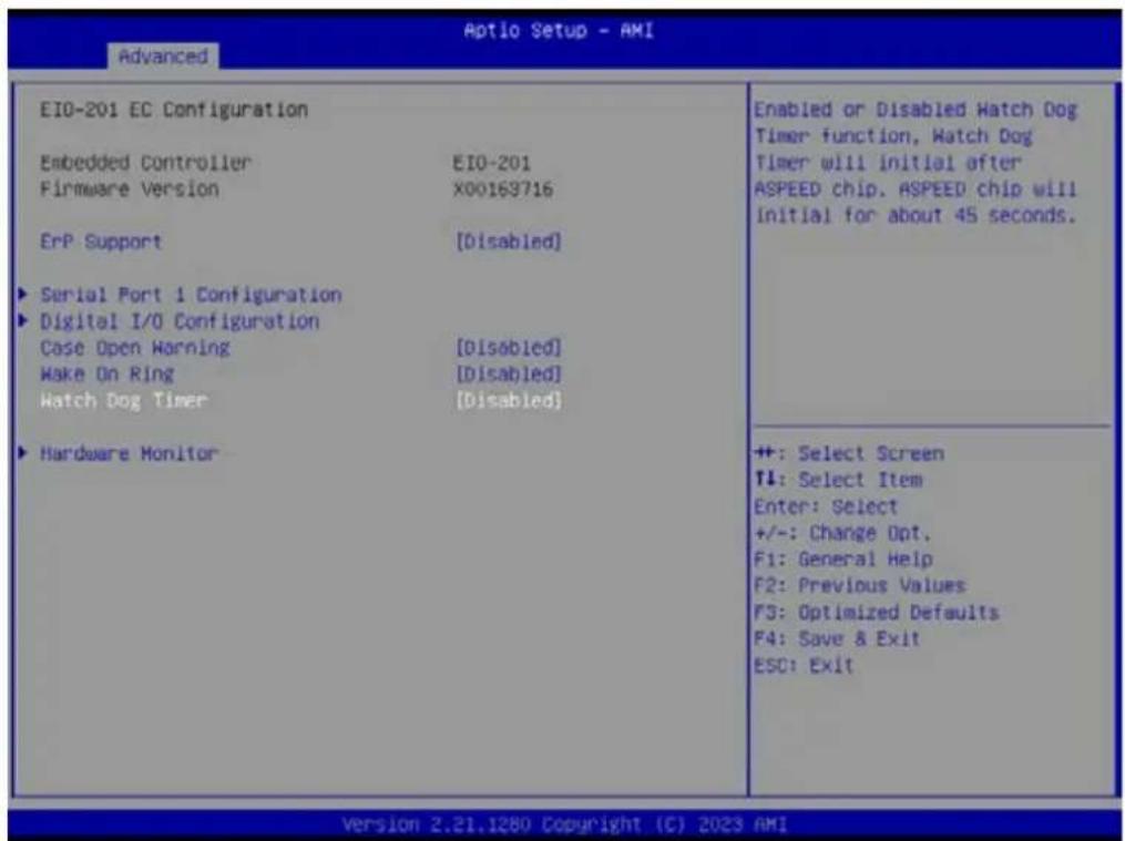
EIO-201 EC Configuration Embedded Controller EIO-201 Firmware Version X00163716 ErP Support [Disabled] Serial Port 1 Configuration Digital I/O Configuration Case Open Warning [Disabled] Make On Ring [Disabled] Watch Dog Timer [Disabled] Hardware Monitor Configure Digital I/O Pins. ++: Select Screen T1: Select Item Enter: Select +/-: Change Opt. F1: General Help F2: Previous Values F3: Optimized Defaults F4: Save & Exit ESC: Exit Version 2.21.1280 Copyright (C) 2023 AMI■ Digital I/O Configuration Configure Digital I/O Pins.
text_image
EIO-201 EC Configuration Embedded Controller EIO-201 Firmware Version X00163716 ErP Support [Disabled] ► Serial Port 1 Configuration ► Digital I/O Configuration Case Open Warning [Disabled] Make On Ring [Disabled] Watch Dog Timer [Disabled] ► Hardware Monitor Enabled or Disabled Hatch Dog Timer function, Watch Dog Timer will initial after ASPEED chip, ASPEED chip will Initial for about 45 seconds. ++: Select Screen T4: Select Item Enter: Select +/-: Change Opt. F1: General Help F2: Previous Values F3: Optimized Defaults F4: Save & Exit ESC: Exit Version 2.21.1280 Copyright (C) 2023 AMI■ Case Open Warning [Disabled]
■ Wake On Ring [Disabled]
■ Watch Dog Timer [Disabled]
Note!

- Watch Dog Timer will initial after ASPEED chip and ASPEED chip will initial for about 45 seconds.
- The beep sounds of Case Open warning temperature is continuous 1 short beep.

text_image
Aptio Setup - AMI Advanced Digital I/O Configuration Digital I/O Pin 1 [Input] Digital I/O Pin 2 [Input] Digital I/O Pin 3 [Input] Digital I/O Pin 4 [Input] Digital I/O Pin 5 [Input] Digital I/O Pin 6 [Input] Digital I/O Pin 7 [Input] Digital I/O Pin 8 [Input] Configure Digital I/O Pin 1. ++ : Select Screen T1: Select Item Enter: Select +/-: Change Opt. F1: General Help F2: Previous Values F3: Optimized Defaults F4: Save & Exit ESC: Exit Version 2.21.1280 Copyright (C) 2023 AMI- Digital I/O Pin 1 [Input]
- Digital I/O Pin 2 [Input]
- Digital I/O Pin 3 [Input]
- Digital I/O Pin 4 [Input]
- Digital I/O Pin 5 [Input]
- Digital I/O Pin 6 [Input]
- Digital I/O Pin 7 [Input]
- Digital I/O Pin 8 [Input]
text_image
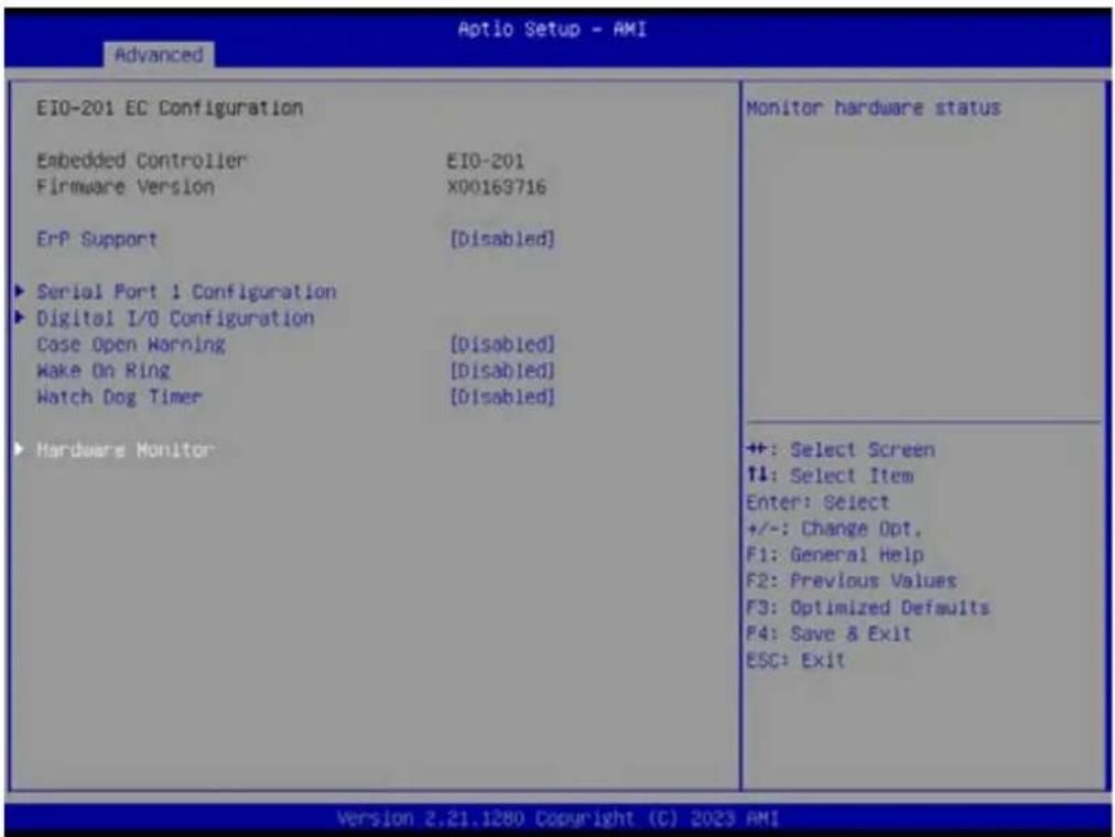
EIO-201 EC Configuration Embedded Controller EIO-201 Firmware Version X00163716 ErP Support [Disabled] ► Serial Port 1 Configuration ► Digital I/O Configuration Case Open Warning [Disabled] Make On Ring [Disabled] Watch Dog Timer [Disabled] ► Hardware Monitor Monitor hardware status ++: Select Screen ↑↓: Select Item Enter: Select +/-: Change Opt. F1: General Help F2: Previous Values F3: Optimized Defaults F4: Save & Exit ESC: Exit Version 2.21.1280 Copyright (C) 2023 AMI■ Hardware Monitor Monitor hardware status

text_image
PC Health Status CPU Temperature : +36.7°C/ +38.0°F System0 Temperature : +40.9°C/ +105.6°F System1 Temperature : +40.1°C/ +104.1°F CPUFAN1 : 0 RPM SYSFAN1 : 4561 RPM SYSFAN2 : 0 RPM SYSFAN3 : 0 RPM SYSFAN4 : 0 RPM +VIN : +12.22 V +VSSB : +5.01 V +VBAT : +2.96 V +VODCR_CPU : +0.76 V +VODCR_SOC : +0.85 V Smart Fan Mode Configuration ACPI Shutdown Temperature [Disabled] CPU Warning Temperature [Disabled] Smart Fan Mode Select ++: Select Screen ↑↓: Select Item Enter: Select +/-: Change Opt. F1: General Help F2: Previous Values F3: Optimized Defaults F4: Save & Exit ESC: Exit Version 2.21.1280 Copyright (C) 2023 AMI■ Smart Fan Mode Configuration
Smart Fan Mode Select
■ ACPI Shutdown Temperature [Disabled]
■ CPU Warning Temperature [Disabled]
Note!

- If actual fan speed is under 500RPM, it will show "0RPM" on BIOS menu and EC tool.
- The beep sounds of CPU warning temperature is continuous 2 short beep and 1 long beep.

text_image
Optio Setup - AMI Advanced Smart Fan Mode Configuration Smart Fan - CPUFAN1 [Auto] Smart Fan - SYSFAN1 [Auto] Smart Fan - SYSFAN2 [Auto] Smart Fan - SYSFAN3 [Auto] Smart Fan - SYSFAN4 [Auto] Control Smart FAN function. Get value from EC and only set value when Save Changes. ++: Select Screen ↑↓: Select Item Enter: Select +/-: Change Opt. F1: General Help F2: Previous Values F3: Optimized Defaults F4: Save & Exit ESC: Exit Version 2.21.1280 Copyright (C) 2023 AMIControl Smart FAN function. Get value from EC and only set value when save changes.
- Smart Fan - CPUFAN1 [Auto]
- Smart Fan - SYSFAN1 [Auto]
- Smart Fan - SYSFAN2 [Auto]
- Smart Fan - SYSFAN3 [Auto]
- Smart Fan - SYSFAN4 [Auto]
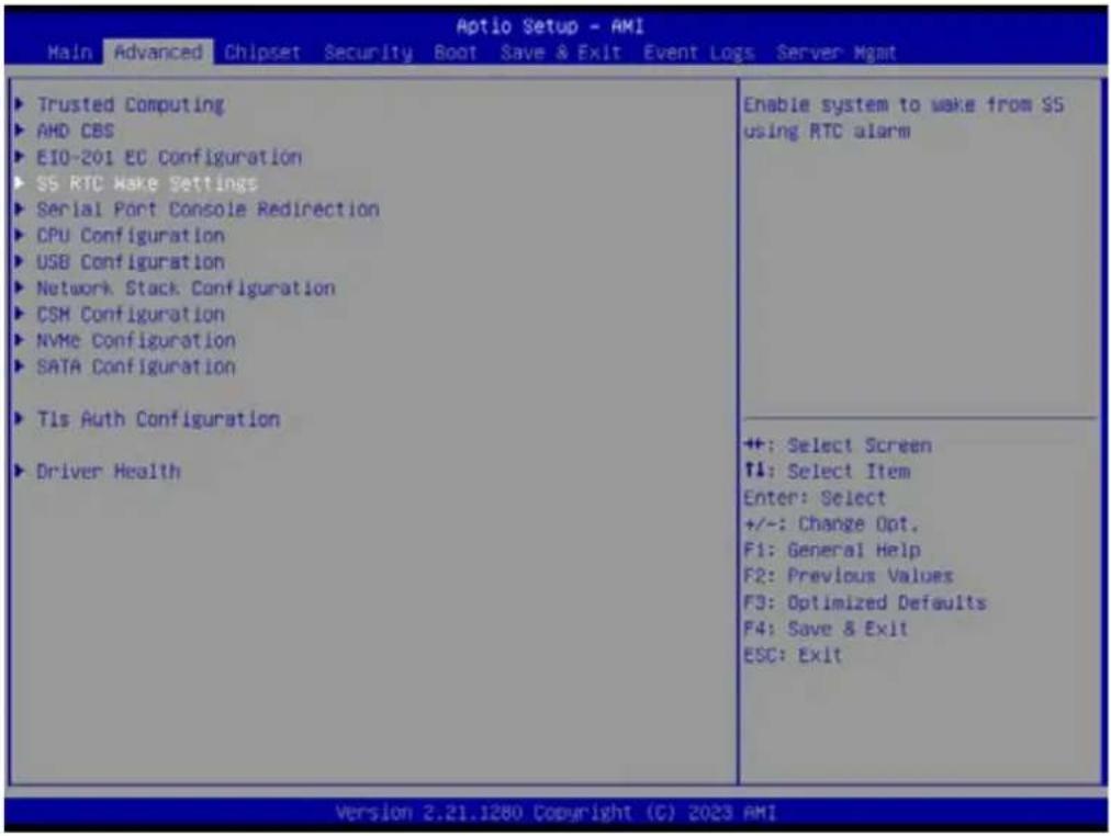
3.2.2.3 S5 RTC Wake Settings
text_image
Aptio Setup - AMI Main Advanced Chipset Security Boot Save & Exit Event Logs Server Mgmt Trusted Computing AMD CBS EIO-201 EC Configuration SS RTC Make Settings Serial Port Console Redirection CPU Configuration USB Configuration Network Stack Configuration CSM Configuration NVMe Configuration SATA Configuration Tls Auth Configuration Driver Health Enable system to wake from SS using RTC alarm ++: Select Screen ↑: Select Item Enter: Select +/-: Change Opt. F1: General Help F2: Previous Values F3: Optimized Defaults F4: Save & Exit ESC: Exit Version 2.21.1280 Copyright (C) 2023 AMI■ Wake system from S5 [Disabled]
![Advantech AIMB-592 - ■ Wake system from S5 [Disabled] - 1](/content/2026/06/1228734/images/88feb4a5fabddea573d850230b6cdd1b9e2389578b72daabc17a81fa3579fc5d.jpg)
text_image
Aptio Setup - AMI Advanced Make system from SS (Disabled) Enable or disable System wake on alarm event. Select FixedTime, system will wake on the hr::min::sec specified. Select DynamicTime , System will wake on the current time + Increase minute(s) ++: Select Screen ↑↓: Select Item Enter: Select +/~: Change Opt. F1: General Help F2: Previous Values F3: Optimized Defaults F4: Save & Exit ESC: Exit Version 2.22.1282 Copyright (C) 2022 AMIEnable or disable System wake on alarm event. Select FixedTime, system will wake on the hr: :min: :sec specified. Select DynamicTime, System will wake on the current time + Increase minute(s)
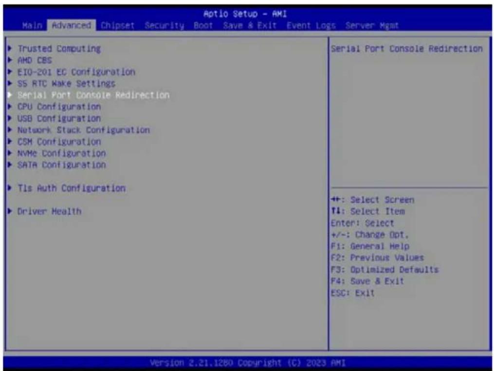
3.2.2.4 Serial Port Console Redirection
text_image
Aptio Setup - AMI Main Advanced Chipset Security Boot Save & Exit Event Logs Server Mgmt Trusted Computing AMD CBS EIO-201 EC Configuration SS RTC Wake Settings Serial Port Console Redirection CPU Configuration USB Configuration Network Stack Configuration CSM Configuration NVMe Configuration SATA Configuration Tls Auth Configuration Driver Health Serial Port Console Redirection +: Select Screen T4: Select Item Enter: Select +/-: Change Opt. F1: General Help F2: Previous Values F3: Optimized Defaults F4: Save & Exit ESC: Exit Version 2.21.1280 Copyright (C) 2023 AMI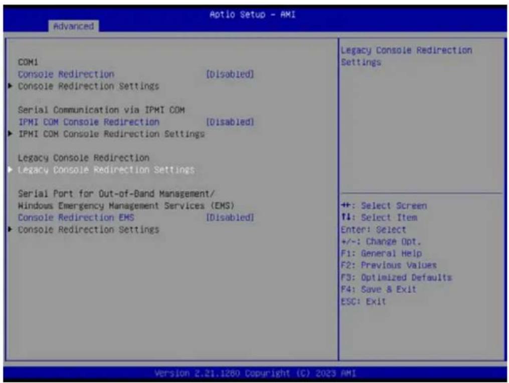
text_image
Aptio Setup - AMI Advanced COM1 Console Redirection [Disabled] ► Console Redirection Settings Serial Communication via IPMI COM IPMI COM Console Redirection [Disabled] ► IPMI COM Console Redirection Settings Legacy Console Redirection ► Legacy Console Redirection Settings Serial Port for Out-of-Band Management/ Windows Emergency Management Services (EMS) Console Redirection EMS [Disabled] ► Console Redirection Settings Legacy Console Redirection Settings ++: Select Screen ↑↓: Select Item Enter: Select +/-: Change Opt. F1: General Help F2: Previous Values F3: Optimized Defaults F4: Save & Exit ESC: Exit Version 2.21.1260 Copyright (C) 2023 AMI- Console Redirection [Disabled]
- IPMI COM Console Redirection [Disabled]
- Console Redirection EMS [Disabled]
Serial Port Console Redirection – Legacy Console Redirection Settings Select a COM port to display redirection of Legacy OS and Legacy OPROM Messages

text_image
Advanced Legacy Console Redirection Settings Redirection COM Port [COM1] Resolution [80x24] Redirect After POST (Always Enable) Select a COM port to display redirection of Legacy OS and Legacy OPROM Messages ++: Select Screen 11: Select Item Enter: Select +/-: Change Opt. F1: General Help F2: Previous Values F3: Optimized Defaults F4: Save & Exit ESC: Exit Version 2.21.1280 Copyright (C) 2023 AMI- Redirection COM Port [COM1]
- Resolution [80x24]
- Redirect After POST [Always Enable]
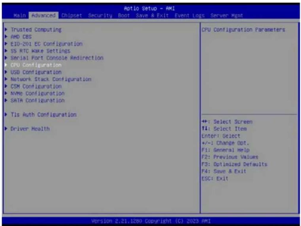
3.2.2.5 CPU Configuration
text_image
Aptio Setup - AMI Main Advanced Chipset Security Boot Save & Exit Event Loss Server Mgmt ► Trusted Computing ► AMD CBS ► EIO-201 EC Configuration ► SS RTC Wake Settings ► Serial Port Console Redirection ► CPU Configuration ► USB Configuration ► Network Stack Configuration ► CSM Configuration ► NVMe Configuration ► SATA Configuration ► Tls Auth Configuration ► Driver Health CPU Configuration Parameters ++ +: Select Screen ↑4: Select Item Enter: Select +/-: Change Opt. F1: General Help F2: Previous Values F3: Optimized Defaults F4: Save & Exit ESC: Exit Version 2.21.1280 Copyright (C) 2023 AMI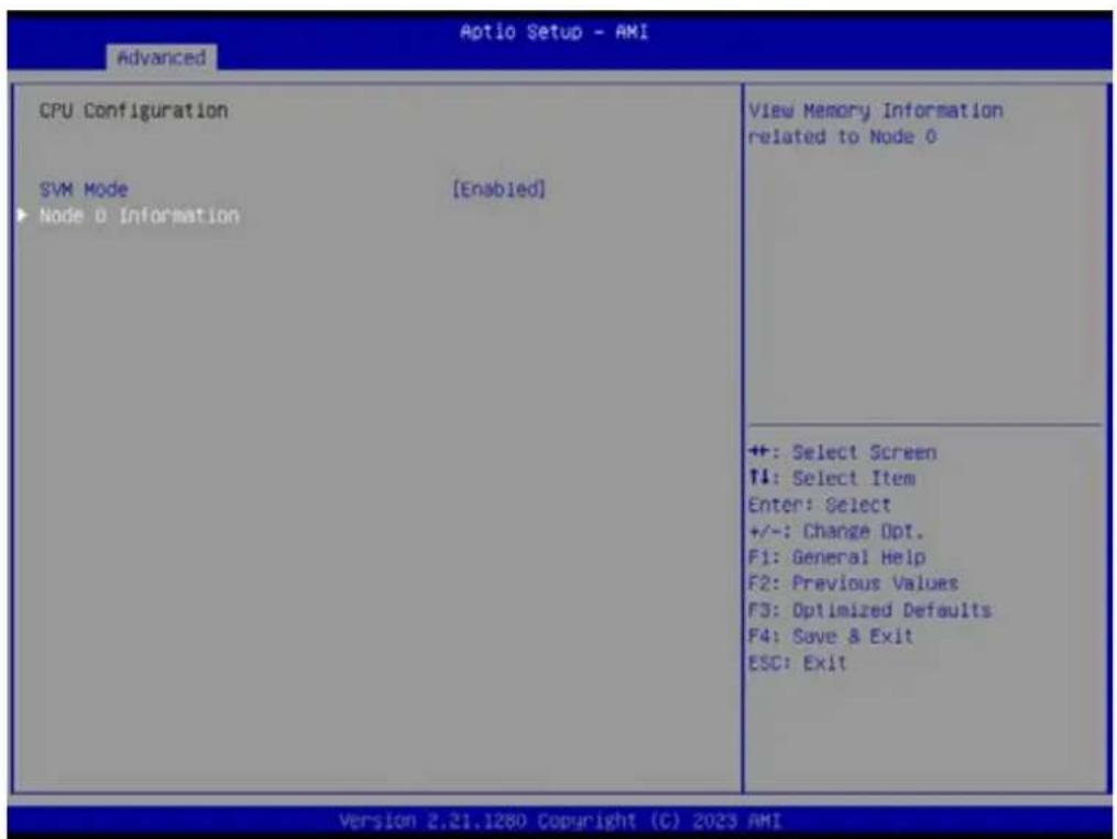
text_image
Advanced Aptio Setup - AMI CPU Configuration SVM Mode [Enabled] ► Node 0 Information View Memory Information related to Node 0 ++ : Select Screen ↑: Select Item Enter: Select +/-: Change Opt. F1: General Help F2: Previous Values F3: Optimized Defaults F4: Save & Exit ESC: Exit Version 2.21.1280 Copyright (C) 2023 AMI- SVM Mode [Enable]
- Node 0 Information
CPU Configuration - Node 0 Information

text_image
Node 0 Information AMD EPYC 7543P 32-Core Processor 32 Cores 64 Threads Running @ 2821 MHz 1100 mV Processor Family: 19h Processor Model: 00h-0Fh Microcode Patch Level: A001173 ----- Cache per Core ---- L1 Instruction Cache: 32 KB/8-way L1 Data Cache: 32 KB/8-way L2 Cache: 512 KB/8-way L3 Cache per Socket: 256 MB/16-way ++: Select Screen ↑↓: Select Item Enter: Select +/-: Change Opt. F1: General Help F2: Previous Values F3: Optimized Defaults F4: Save & Exit ESC: Exit Version 2.21.1260 Copyright (C) 2023 AMI3.2.2.6 USB Configuration

text_image
Aptio Setup - AMI Main Advanced Chipset Security Boot Save & Exit Event Logs Server Mgmt ► Trusted Computing ► AMD CBS ► EIO-201 EC Configuration ► SS RTC Wake Settings ► Serial Port Console Redirection ► CPU Configuration ► USB Configuration ► Network Stack Configuration ► CSM Configuration ► NVMe Configuration ► SATA Configuration ► Tls Auth Configuration ► Driver Health USB Configuration Parameters ++ +: Select Screen T1: Select Item Enter: Select +/-: Change Opt. F1: General Help F2: Previous Values F3: Optimized Defaults F4: Save & Exit ESC: Exit Version 2.21.1280 Copyright (C) 2023 AMI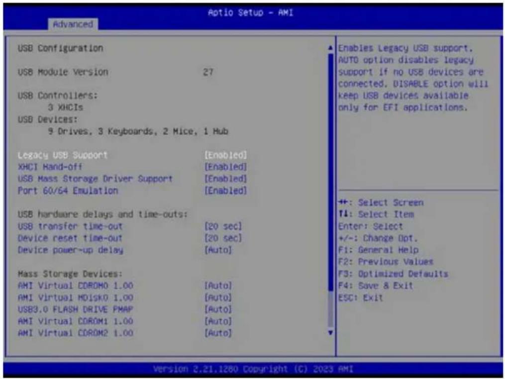
text_image
Optio Setup - AMI Advanced USB Configuration USB Module Version 27 USB Controllers: 3 XHCIs USB Devices: 9 Drives, 3 Keyboards, 2 Mice, 1 Hub Legacy USB Support [Enabled] XHCI Hand-off [Enabled] USB Mass Storage Driver Support [Enabled] Port 60/64 Emulation [Enabled] USB hardware delays and time-outs: USB transfer time-out [20 sec] Device reset time-out [20 sec] Device power-up delay [Auto] Mass Storage Devices: AMI Virtual CDROM0 1.00 [Auto] AMI Virtual MDISK0 1.00 [Auto] USB3.0 FLASH DRIVE PMAP [Auto] AMI Virtual CDROM1 1.00 [Auto] AMI Virtual CDROM2 1.00 [Auto] Enables Legacy USB support. AUTO option disables legacy support if no USB devices are connected. DISABLE option will keep USB devices available only for EFI applications. +: Select Screen ↑: Select Item Enter: Select +/-: Change Opt. F1: General Help F2: Previous Values F3: Optimized Defaults F4: Save & Exit ESC: Exit Version 2.21.1280 Copyright (C) 2023 AMI■ Legacy USB Support [Enabled]
\Enables Legacy USB support, AUTO option disables legacy support if no USB devices are connected. DISABLE option will keep USB devices available only for EFI applications.
■ XHCI Hand-off [Enabled]
USB Mass Storage Driver Support [Enabled]
■ Port 60/64 Emulation [Enabled]
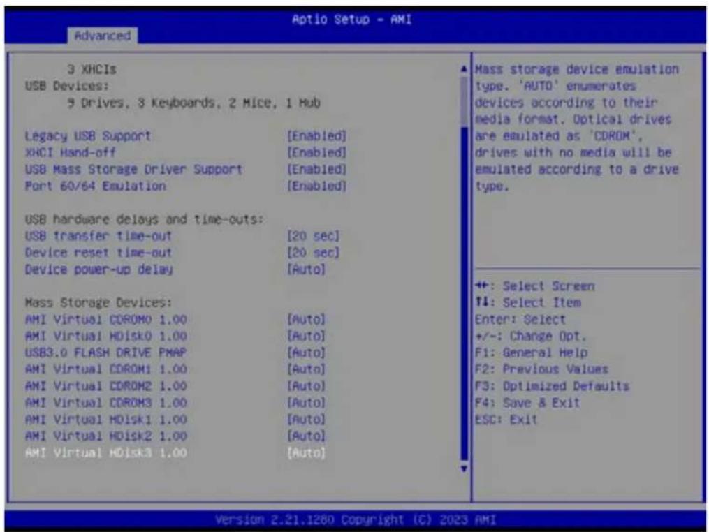
text_image
3 XHCIs USB Devices: 3 Drives, 3 Keyboards, 2 Mice, 1 Hub Legacy USB Support [Enabled] XHCI Hand-off [Enabled] USB Mass Storage Driver Support [Enabled] Port 60/64 Emulation [Enabled] USB hardware delays and time-outs: USB transfer time-out [20 sec] Device reset time-out [20 sec] Device power-up delay [Auto] Mass Storage Devices: AMI Virtual COROM0 1.00 [Auto] AMI Virtual HDisk0 1.00 [Auto] USB3.0 FLASH DRIVE PMAP [Auto] AMI Virtual COROM1 1.00 [Auto] AMI Virtual COROM2 1.00 [Auto] AMI Virtual COROM3 1.00 [Auto] AMI Virtual HDisk1 1.00 [Auto] AMI Virtual HDisk2 1.00 [Auto] AMI Virtual HDisk3 1.00 [Auto] Mass storage device emulation type. 'AUTO' enumerates devices according to their media format. Optical drives are emulated as 'COROM', drives with no media will be emulated according to a drive type. ++: Select Screen ↑: Select Item Enter: Select +/-: Change Opt. F1: General Help F2: Previous Values F3: Optimized Defaults F4: Save & Exit ESC: Exit Version 2.21.1280 Copyright (C) 2023 AMI3.2.2.7 Network Stack Configuration

text_image
Aptio Setup - AMI Main Advanced Chipset Security Boot Save & Exit Event Logs Server Mgmt Trusted Computing AMD CBS EIO-201 EC Configuration SS RTC Make Settings Serial Port Console Redirection CPU Configuration USB Configuration Network Stack Configuration CSM Configuration NVMe Configuration SATA Configuration Tls Auth Configuration Driver Health Network Stack Settings +: Select Screen T1: Select Item Enter: Select +/-: Change Opt. F1: General Help F2: Previous Values F3: Optimized Defaults F4: Save & Exit ESC: Exit Version 2.21.1280 Copyright (C) 2023 AMI
text_image
Advanced Aptio Setup - AMI Network Stack (Disabled) Enable/Disable UEFI Network Stack ++: Select Screen T4: Select Item Enter: Select +/-: Change Opt. F1: General Help F2: Previous Values F3: Optimized Defaults F4: Save & Exit ESC: Exit Version 2.21.1280 Copyright (C) 2023 AMI■ Network Stack [Disabled] Enable/Disable UEFI Network Stack
3.2.2.8 CSM Configuration

text_image
Aptio Setup - AMI Main Advanced Chipset Security Boot Save & Exit Event Logs Server Mgmt ► Trusted Computing ► AMD CBS ► EIO-201 EC Configuration ► SS RTC Wake Settings ► Serial Port Console Redirection ► CPU Configuration ► USB Configuration ► Network Stack Configuration ► CSM Configuration ► NVMe Configuration ► SATA Configuration ► Tls Auth Configuration ► Driver Health CSM configuration: Enable/Disable, Option ROM execution settings, etc. ++ +: Select Screen T4: Select Item Enter: Select +/-: Change Opt. F1: General Help F2: Previous Values F3: Optimized Defaults F4: Save & Exit ESC: Exit Version 2.21.1280 Copyright (C) 2023 AMI
text_image
Aptio Setup - AMI Advanced Compatibility Support Module Configuration CSM16 Module Version 07.84 GateA20 Active [Upon Request] INT19 Trap Response [Immediate] Boot option filter [UEFI only] Option ROM execution Network [UEFI] Storage [UEFI] Video [UEFI] Other PCI devices [UEFI] UPON REQUEST - GA20 can be disabled using BIOS services. ALWAYS - do not allow disabling GA20: this option is useful when any RT code is executed above IMB. ++: Select Screen ↑: Select Item Enter: Select +/-: Change Opt. F1: General Help F2: Previous Values F3: Optimized Defaults F4: Save & Exit ESC: Exit Version 2.21.1280 Copyright (C) 2023 AMI■ GateA20 Active [Upon Request]
UPON REQUEST – GA20 can be disabled using BIOS services.
ALWAYS – do not allow disabling GA20; this option is useful when any RT code is executed above 1MB.
■ INT19 Trap Response [Immediate]
■ Boot option filter [UEFI only]
Network [UEFI]
Storage [UEFI]
Video [UEFI]
■ Other PCI devices [UEFI]
3.2.2.9 NVMe Configuration
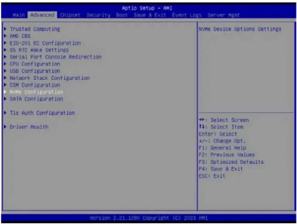
text_image
Aptio Setup - AMI Main Advanced Chipset Security Boot Save & Exit Event Logs Server Mgmt ▶ Trusted Computing ▶ AMD CBS ▶ EIO-201 EC Configuration ▶ SS RTC Make Settings ▶ Serial Port Console Redirection ▶ CPU Configuration ▶ USB Configuration ▶ Network Stack Configuration ▶ CSM Configuration ▶ NVMe Configuration ▶ SATA Configuration ▶ Tls Auth Configuration ▶ Driver Health NVMe Device Options Settings ++: Select Screen ↑↓: Select Item Enter: Select +/-: Change Opt. F1: General Help F2: Previous Values F3: Optimized Defaults F4: Save & Exit ESC: Exit Version 2.21.1280 Copyright (C) 2023 AMI3.2.2.10 SATA Configuration
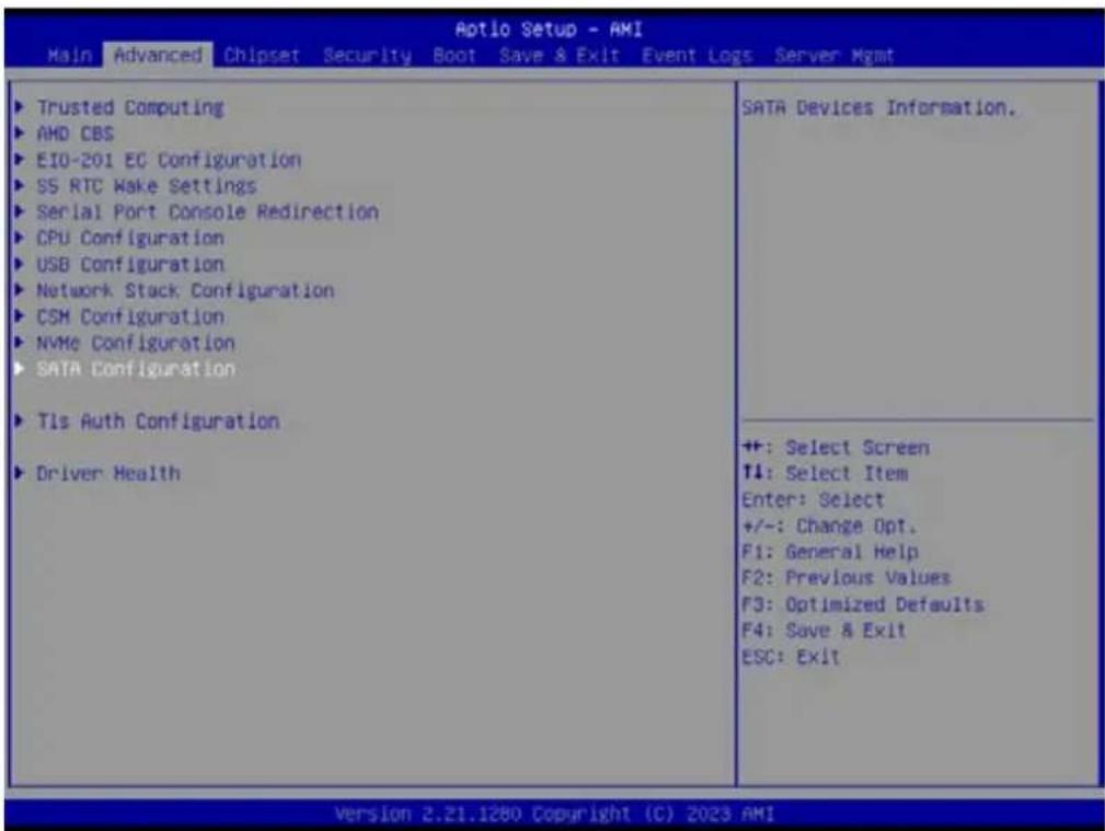
text_image
Aptio Setup - AMI Main Advanced Chipset Security Boot Save & Exit Event Logs Server Mgmt ▶ Trusted Computing ▶ AMD CBS ▶ EIO-201 EC Configuration ▶ SS RTC Make Settings ▶ Serial Port Console Redirection ▶ CPU Configuration ▶ USB Configuration ▶ Network Stack Configuration ▶ CSM Configuration ▶ NVMe Configuration ▶ SATA Configuration ▶ Tls Auth Configuration ▶ Driver Health SATA Devices Information. ++: Select Screen T4: Select Item Enter: Select +/-: Change Opt. F1: General Help F2: Previous Values F3: Optimized Defaults F4: Save & Exit ESC: Exit Version 2.21.1280 Copyright (C) 2023 AMI3.2.2.11 TIs Auth Configuration
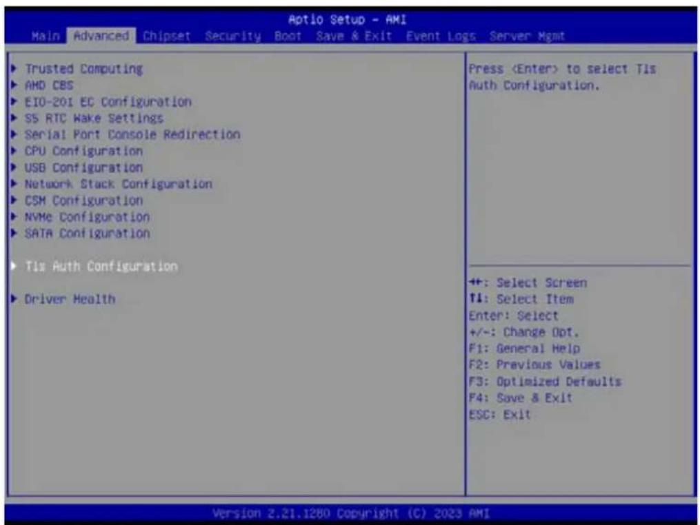
text_image
Aptio Setup - AMI Main Advanced Chipset Security Boot Save & Exit Event Logs Server Mgmt ► Trusted Computing ► AMD CBS ► EIO-201 EC Configuration ► S5 RTC Wake Settings ► Serial Port Console Redirection ► CPU Configuration ► USB Configuration ► Network Stack Configuration ► CSM Configuration ► NVMe Configuration ► SATA Configuration ► Tls Auth Configuration ► Driver Health Press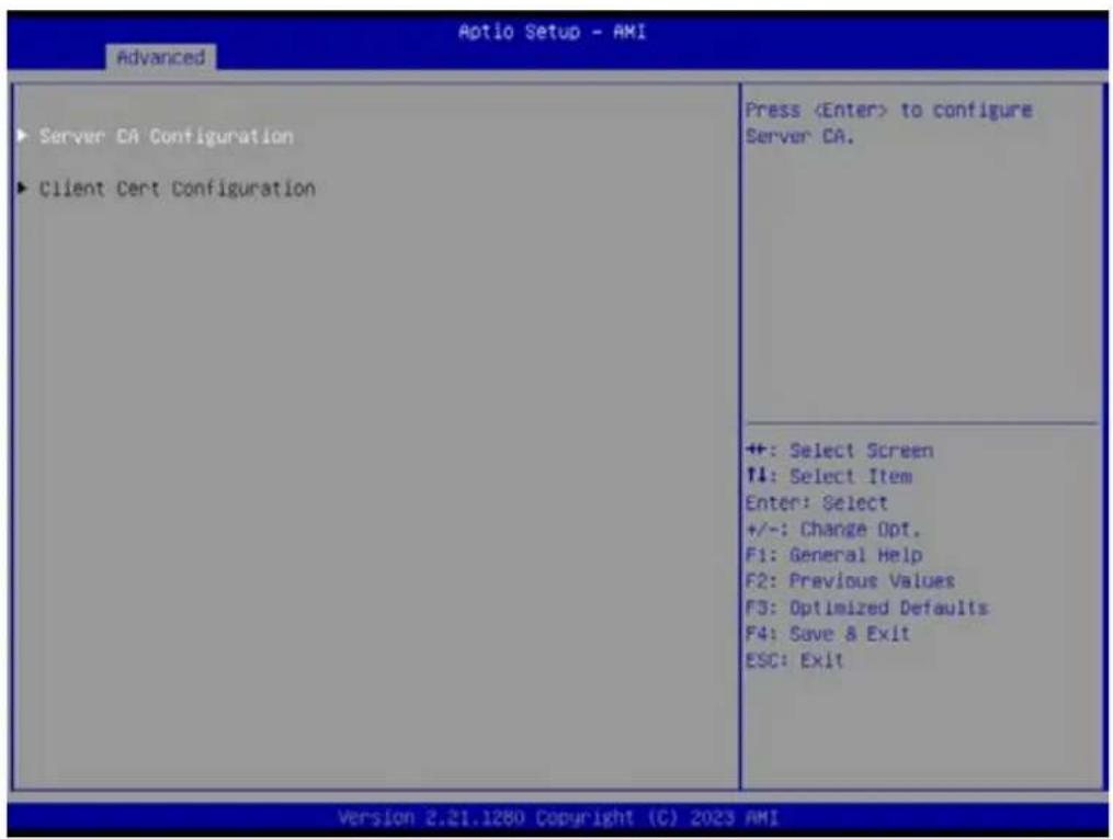
text_image
Aptio Setup - AMI Advanced ► Server CA Configuration ► Client Cert Configuration Press– Server CA Configuration
– Client Cert Configuration
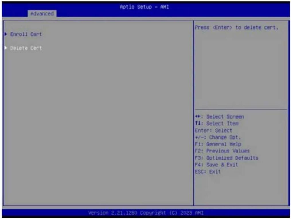
Server CA Configuration – Enroll Cert

text_image
Aptio Setup - AMI Advanced ► Enroll Cert ► Delete Cert PressServer CA Configuration – Enroll Cert – Enroll Cert Using File
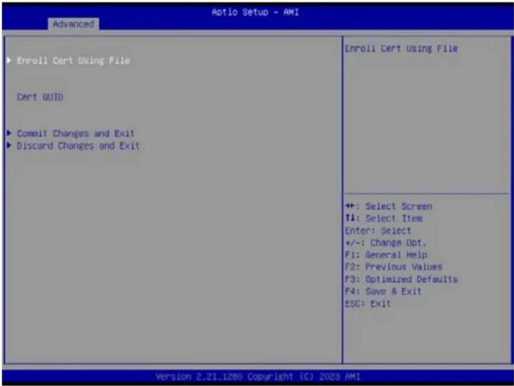
text_image
Aptio Setup - AMI Advanced ► Enroll Cert Using File Cerct GUID ► Commit Changes and Exit ► Discard Changes and Exit Enroll Cert Using File ++ +: Select Screen ↑↓: Select Item Enter: Select +/-: Change Opt. F1: General Help F2: Previous Values F3: Optimized Defaults F4: Save & Exit ESC: Exit Version 2.21.1280 Copyright (C) 2023 AMIServer CA Configuration – Delete Cert
text_image
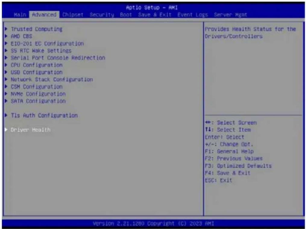
Aptio Setup - AMI Advanced ► Enroll Cert ► Delete Cert Press3.2.2.12 Driver Health
Provides Health Status for the Drivers/Controllers
text_image
Aptio Setup - AMI Main Advanced Chipset Security Boot Save & Exit Event Logs Server Mgmt ► Trusted Computing ► AMD CBS ► E10-201 EC Configuration ► SS RTC Make Settings ► Serial Port Console Redirection ► CPU Configuration ► USB Configuration ► Network Stack Configuration ► CSM Configuration ► NVMe Configuration ► SATA Configuration ► Tls Auth Configuration ► Driver Health Provides Health Status for the Drivers/Controllers +: Select Screen ↑: Select Item Enter: Select +/-: Change Opt. F1: General Help F2: Previous Values F3: Optimized Defaults F4: Save & Exit ESC: Exit Version 2.21.1280 Copyright (C) 2023 AMI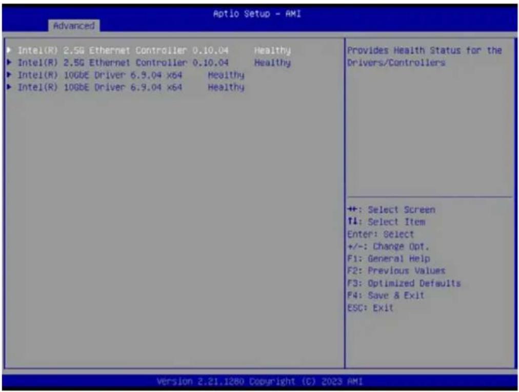
text_image
Aptio Setup - AMI Advanced ► Intel(R) 2.5G Ethernet Controller 0.10.04 Healthy ► Intel(R) 2.5G Ethernet Controller 0.10.04 Healthy ► Intel(R) 10GbE Driver 6.9.04 x64 Healthy ► Intel(R) 10GbE Driver 6.9.04 x64 Healthy Provides Health Status for the Drivers/Controllers ++ : Select Screen ↑: Select Item Enter: Select +/-: Change Opt. F1: General Help F2: Previous Values F3: Optimized Defaults F4: Save & Exit ESC: Exit Version 2.21.1280 Copyright (C) 2023 AMI3.2.3 Chipset Configuration Setting
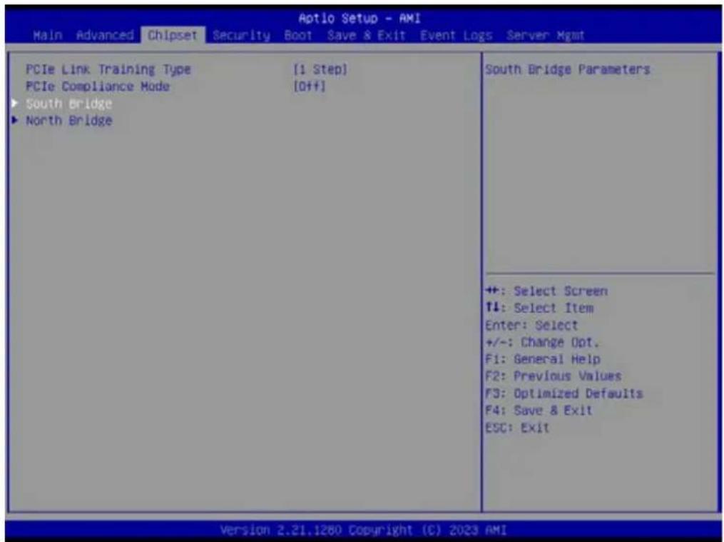
Select the chipset tab from the BIOS setup screen to enter the Chipset Setup screen. Users can select any item in the left frame of the screen, such as South Bridge Parameters, to go to the sub menu for that item. Users can display a Chipset Setup option by highlighting it using the
text_image
Aptio Setup - AMI Main Advanced Chipset Security Boot Save & Exit Event Logs Server Mgmt PCIe Link Training Type [1 Step] PCIe Compliance Mode [Off] ► South Bridge ► North Bridge South Bridge Parameters ++ : Select Screen ↑↓: Select Item Enter: Select +/-: Change Opt. F1: General Help F2: Previous Values F3: Optimized Defaults F4: Save & Exit ESC: Exit Version 2.21.1260 Copyright (C) 2023 AMI3.2.3.1 South Bridge
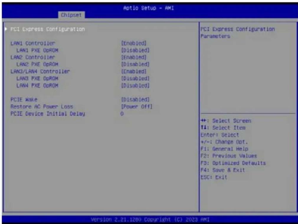
text_image
Aotio Setup - AMI Chipset PCI Express Configuration LAN1 Controller [Enabled] LAN1 PXE OpROM [Disabled] LAN2 Controller [Enabled] LAN2 PXE OpROM [Disabled] LAN3/LAN4 Controller [Enabled] LAN3 PXE OpROM [Disabled] LAN4 PXE OpROM [Disabled] PCIE Make [Disabled] Restore AC Power Loss [Power Off] PCIE Device Initial Delay 0 PCI Express Configuration Parameters ++ : Select Screen ↑↓: Select Item Enter: Select +/-: Change Opt. F1: General Help F2: Previous Values F3: Optimized Defaults F4: Save & Exit ESC: Exit Version 2.21.1280 Copyright (C) 2023 AMI■ LAN1 Controller [Enable]
■ LAN2 Controller [Enable]
■ LAN3/4 Controller [Enable]
■ PCIE Wake [Disabled]
■ Restore AC Power Loss [Power off]
■ PCIE Device Initial Delay 0
■ PCI Express Configuration User can enable or disable PCI express devices.

text_image
Aptio Setup - AMI Chipset PCI Express Configuration M.2 M-key Slot ASPM Mode Control PCIe ×16 Slot1 ASPM Mode Control PCIe ×16 Slot2 ASPM Mode Control PCIe ×16 Slot3 ASPM Mode Control PCIe ×16 Slot4 ASPM Mode Control LAN1 Controller ASPM Mode Control LAN2 Controller ASPM Mode Control LAN3/LAN4 Controller ASPM Mode Control [Enabled] [Disabled] [Enabled] [Disabled] [Enabled] [Disabled] [Enabled] [Disabled] Enable/Disable M.2 M-key Slot device. ++: Select Screen ↑: Select Item Enter: Select +/-: Change Opt. F1: General Help F2: Previous Values F3: Optimized Defaults F4: Save & Exit ESC: Exit Version 2.21.1280 Copyright (C) 2023 AMI- M.2 M-key Slot [Enabled]
- PCIe x16 Slot1 [Enabled]
- PCIe x16 Slot2 [Enabled]
- PCIe x16 Slot3 [Enabled]
- PCIe x16 Slot4 [Enabled]
- LAN1 Controller [Enabled]
- LAN2 Controller [Enabled]
- LAN3/LAN4 Controller [Enabled]
3.2.3.2 North Bridge
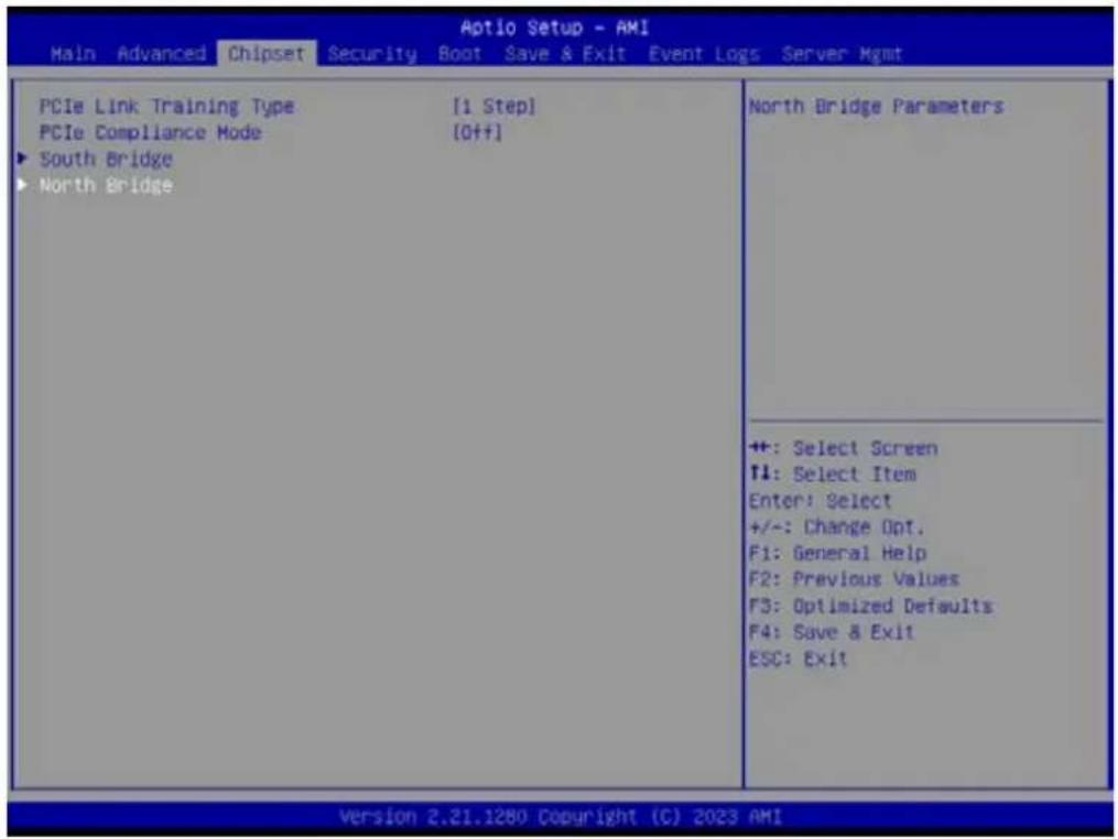
text_image
Aptio Setup - AMI Main Advanced Chipset Security Boot Save & Exit Event Logs Server Mgmt PCIe Link Training Type [1 Step] PCIe Compliance Mode [Off+] ► South Bridge ► North Bridge North Bridge Parameters +: Select Screen ↑: Select Item Enter: Select +/-: Change Opt. F1: General Help F2: Previous Values F3: Optimized Defaults F4: Save & Exit ESC: Exit ++: Select Screen ↑: Select Item Enter: Select +/-: Change Opt. F1: General Help F2: Previous Values F3: Optimized Defaults F4: Save & Exit ESC: Exit Version 2.21.1280 Copyright (C) 2023 AMI
text_image
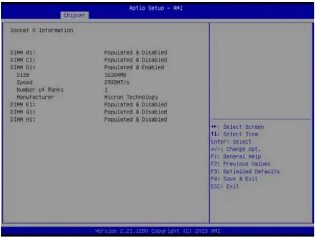
Aptio Setup - AMI Chipset North Bridge Configuration Memory Information Total Memory: 16384 MB (DDR4) Socket 0 Information View Information related to Socket 0 +: Select Screen 11: Select Item Enter: Select +/-: Change Opt. F1: General Help F2: Previous Values F3: Optimized Defaults F4: Save & Exit ESC: Exit Version 2.21.1280 Copyright (C) 2023 AMI■ Memory Information
- Socket 0 Information
text_image
Aptio Setup - AMI Chipset Socket 0 Information DIMM A1: Populated & Disabled DIMM C1: Populated & Disabled DIMM D1: Populated & Enabled Size 16384MB Speed 2933MT/s Number of Ranks 1 Manufacturer Micron Technology DIMM E1: Populated & Disabled DIMM G1: Populated & Disabled DIMM H1: Populated & Disabled ++: Select Screen T1: Select Item Enter: Select +/-: Change Opt. F1: General Help F2: Previous Values F3: Optimized Defaults F4: Save & Exit ESC: Exit Version 2.21.1280 Copyright (C) 2023 AMI3.2.4 Security Setting

text_image
Aptio Setup - AMI Main Advanced Chipset Security Boot Save & Exit Event Logs Server Mgmt Password Description If ONLY the Administrator's password is set, then this only limits access to Setup and is only asked for when entering Setup. If ONLY the User's password is set, then this is a power on password and must be entered to boot or enter Setup. In Setup the User will have Administrator rights. The password length must be in the following range: Minimum length 3 Maximum length 20 Administrator Password User Password Secure Boot Secure Boot configuration ++: Select Screen T1: Select Item Enter: Select +/-: Change Opt. F1: General Help F2: Previous Values F3: Optimized Defaults F4: Save & Exit ESC: Exit Version 2.21.1280 Copyright (C) 2023 AMI3.2.4.1 Secure Boot

text_image
Aptio Setup - AMI Security System Mode Secure Boot Secure Boot Mode Restore Factory Keys Reset To Setup Mode Key Management Setup [Enabled] Inactive [Standard] Secure Boot feature is Active if Secure Boot is Enabled, Platform Key(PK) is enrolled and the System is in User mode. The mode change requires platform reset ++: Select Screen ↑1: Select Item Enter: Select +/-: Change Opt. F1: General Help F2: Previous Values F3: Optimized Defaults F4: Save & Exit ESC: Exit Version 2.22.1282 Copyright (C) 2022 AMI3.2.5 Boot Setting

text_image
Aptio Setup - AMI Main Advanced Chipset Security Boot Save & Exit Event Logs Server Mgmt Boot Configuration Setup Prompt Timeout Bootup NumLock State Quiet Boot Boot Option Priorities Boot Option #1 1 [On] [Disabled] [UEFI: USB3.0 FLASH DRIVE PMAP, Partition 1 (USB3.0 FLASH DRIVE PMAP)] Number of seconds to wait for setup activation key. 65S3S(0xFFFF) means indefinite waiting. ++ : Select Screen T4: Select Item Enter: Select +/-: Change Opt. F1: General Help F2: Previous Values F3: Optimized Defaults F4: Save & Exit ESC: Exit Version 2.21.1280 Copyright (C) 2023 AMI■ Setup Prompt Timeout Number of seconds to wait for setup activation key.
■ Bootup NumLock
State Select the keyboard NumLock state as "On" or "Off".
- Quiet Boot
Enable or Disable the quiet boot option.
■ Boot Option Priorities Sets the system boot priorities.
3.2.6 Save & Exit
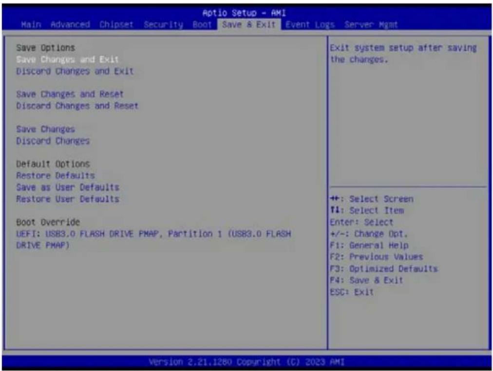
text_image
Aptio Setup - AMI Main Advanced Chipset Security Boot Save & Exit Event Logs Server Mgmt Save Options Save Changes and Exit Discard Changes and Exit Save Changes and Reset Discard Changes and Reset Save Changes Discard Changes Default Options Restore Defaults Save as User Defaults Restore User Defaults Boot Override UEFI: USB3.0 FLASH DRIVE PMAP, Partition 1 (USB3.0 FLASH DRIVE PMAP) Exit system setup after saving the changes. +: Select Screen F1: Select Item Enter: Select +/-: Change Opt. F1: General Help F2: Previous Values F3: Optimized Defaults F4: Save & Exit ESC: Exit Version 2.21.1280 Copyright (C) 2023 AMI■ Save Changes and Exit
Exit system setup after saving the changes.
- Discard Changes and Exit
Exit system setup without saving any changes.
■ Save Changes and Reset
Reset the system after saving changes.
- Discard Changes and Reset
Reset system setup without saving any changes.
■ Save Changes
Save changes done so far to any of the setup options.
- Discard Changes
Discard changes done so far to any of the setup options.
- Restore Defaults
Restore/Load default values for all the setup options.
■ Save as User Defaults
Save the changes done so far as user defaults.
- Restore User Defaults
Restore the user defaults to all the setup options.
3.2.7 Event Logs
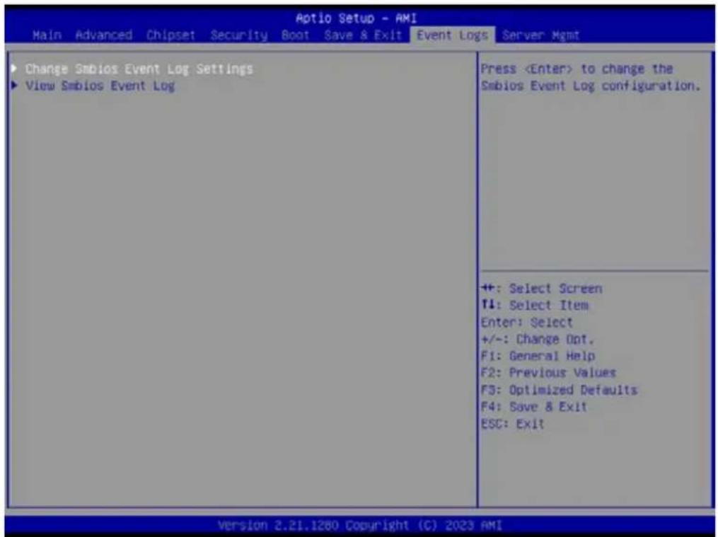
text_image
Aptio Setup - AMI Main Advanced Chipset Security Boot Save & Exit Event Logs Server Mgmt Change Smbios Event Log Settings View Smbios Event Log Press■ Change Smbios Event Log Settings

text_image
Aptio Setup - AMI Event Logs Enabling/Disabling Options Smbios Event Log [Enabled] Erasing Settings Erase Event Log [No] When Log is Full [Do Nothing] Smbios Event Log Standard Settings Log System Boot Event [Enabled] MECI 1 METH 60 Custom Options Log EFI Status Code [Enabled] Convert EFI Status Codes to [Disabled] Standard Smbios Type NOTE: All values changed here do not take effect until computer is restarted. Change this to enable or disable all features of Smbios Event Logging during boot. ++: Select Screen T4: Select Item Enter: Select +/-: Change Opt. F1: General Help F2: Previous Values F3: Optimized Defaults F4: Save & Exit ESC: Exit Version 2.21.1280 Copyright (C) 2023 AMI■ View Smbios Event log
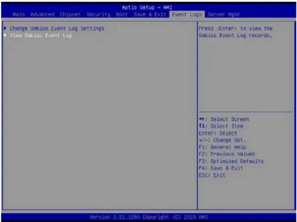
text_image
Aptio Setup - AMI Main Advanced Chipset Security Boot Save & Exit Event Logs Server Mgmt Change Smbios Event Log Settings View Smbios Event Log Press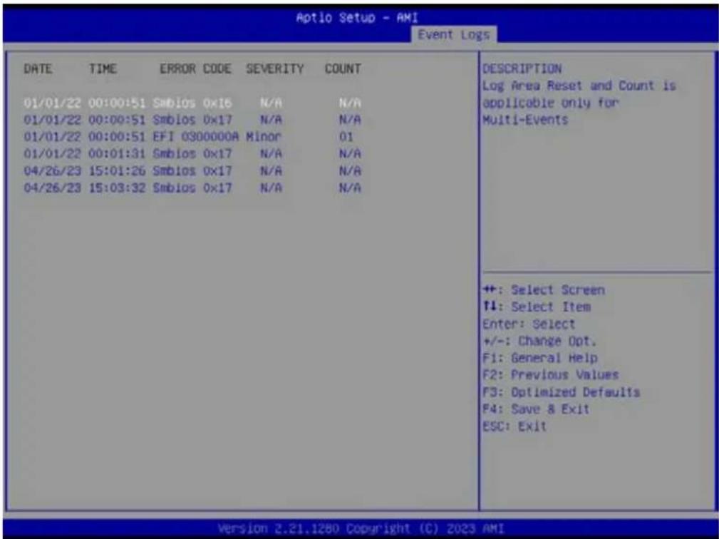
text_image
Aptio Setup - AMI Event Logs DATE TIME ERROR CODE SEVERITY COUNT 01/01/22 00:00:51 Smbios 0x16 N/A N/A 01/01/22 00:00:51 Smbios 0x17 N/A N/A 01/01/22 00:00:51 EFI 0300000A Minor 01 01/01/22 00:01:31 Smbios 0x17 N/A N/A 04/26/23 15:01:26 Smbios 0x17 N/A N/A 04/26/23 15:03:32 Smbios 0x17 N/A N/A DESCRIPTION Log Area Reset and Count is applicable only for Multi-Events ++: Select Screen ↑↓: Select Item Enter: Select +/-: Change Opt. F1: General Help F2: Previous Values F3: Optimized Defaults F4: Save & Exit ESC: Exit Version 2.21.1280 Copyright (C) 2023 AMI3.2.8 Server Mgmt
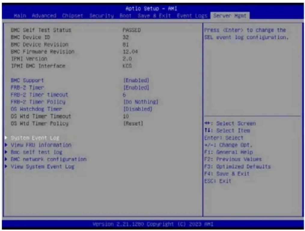
text_image
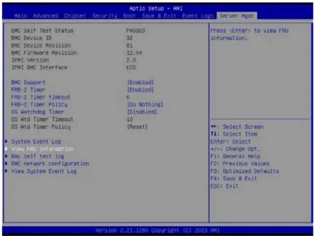
Aptio Setup - AMI Main Advanced Chipset Security Boot Save & Exit Event Logs Server Mgmt BMC Self Test Status PASSED BMC Device ID 32 BMC Device Revision 81 BMC Firmware Revision 12.04 IPMI Version 2.0 IPMI BMC Interface KCS BMC Support [Enabled] FRB-2 Timer [Enabled] FRB-2 Timer timeout 6 FRB-2 Timer Policy [Do Nothing] OS Watchdog Timer [Disabled] OS Wtd Timer Timeout 10 OS Wtd Timer Policy [Reset] System Event Log View FRU information Bmc self test log BMC network configuration View System Event Log PressBMC Support
Enable or Disable interfaces to communicate with BMC.
OS Watchdog Timer
If enabled, this starts a BIOS timer which can only be shut off by Management Software after the OS loads.
3.2.8.1 System Event Log

text_image
Aptio Setup - AMI Main Advanced Chipset Security Boot Save & Exit Event Logs Server Mgmt BMC Self Test Status PASSED BMC Device ID 32 BMC Device Revision 81 BMC Firmware Revision 12.04 IPMI Version 2.0 IPMI BMC Interface KCS BMC Support [Enabled] FRB-2 Timer [Enabled] FRB-2 Timer timeout 6 FRB-2 Timer Policy [Do Nothing] OS Watchdog Timer [Disabled] OS Wtd Timer Timeout 10 OS Wtd Timer Policy [Reset] System Event Log View FRU information Bmc self test log BMC network configuration View System Event Log Press
text_image
Aptio Setup - AMI Server: Mgmt Enabling/Disabling Options SEL Components [Enabled] Erasing Settings Erase SEL [No] Custom EFI Logging Options Log EFI Status Codes [Error code] NOTE: All values changed here do not take effect until computer is restarted. Change this to enable or disable event logging for error/progress codes during boot. ++: Select Screen f1: Select Item Enter: Select +/-: Change Opt. F1: General Help F2: Previous Values F3: Optimized Defaults F4: Save & Exit ESC: Exit Version 2.21.1280 Copyright (C) 2023 AMI■ SEL Components [Enabled]
Erase SEL [No]
Log EFI Status Codes [Error code]
3.2.8.2 View FRU information
text_image
Aotio Setup - AMI Main Advanced Chipset Security Boot Save & Exit Event Logs Server Mgmt BMC Self Test Status PASSED BMC Device ID 32 BMC Device Revision 81 BMC Firmware Revision 12.04 IPMI Version 2.0 IPMI BMC Interface KCS BMC Support [Enabled] FRB-2 Timer [Enabled] FRB-2 Timer Timeout 6 FRB-2 Timer Policy [Do Nothing] OS Watchdog Timer [Disabled] OS Wtd Timer Timeout 10 OS Wtd Timer Policy [Reset] ► System Event Log ► View FRU information ► Bmc self test log ► BMC network configuration ► View System Event Log Press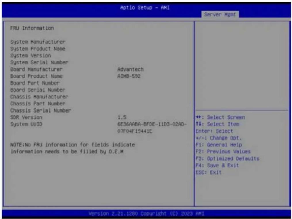
text_image
Aptio Setup - AMI Server Mgmt FRU Information System Manufacturer System Product Name System Version System Serial Number Board Manufacturer Advantech Board Product Name AIMB-592 Board Part Number Board Serial Number Chassis Manufacturer Chassis Part Number Chassis Serial Number SDR Version 1.5 System UUID 6E36AABA-BFDE-1103-02AD- 07F04F19441E NOTE:No FRU information for fields indicate information needs to be filled by 0.E.M ++: Select Screen ↑: Select Item Enter: Select +/-: Change Opt. F1: General Help F2: Previous Values F3: Optimized Defaults F4: Save & Exit ESC: Exit Version 2.21.1280 Copyright (C) 2023 AMI3.2.8.3 BMC Self Test Log
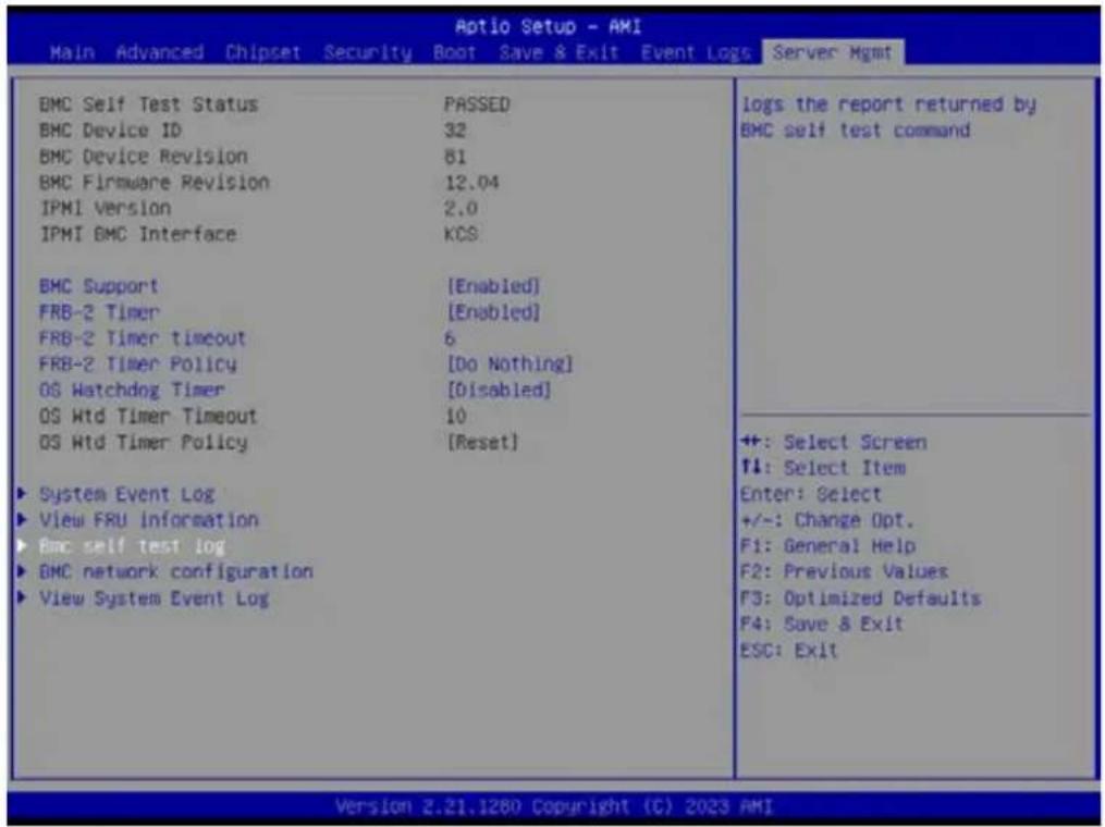
text_image
Aptio Setup - AMI Main Advanced Chipset Security Boot Save & Exit Event Logs Server Mgmt BMC Self Test Status PASSED BMC Device ID 32 BMC Device Revision 81 BMC Firmware Revision 12.04 IPMI Version 2.0 IPMI GMC Interface KCS BMC Support [Enabled] FRB-2 Timer [Enabled] FRB-2 Timer Timeout 6 FRB-2 Timer Policy [Do Nothing] OS Watchdog Timer [Disabled] OS Wtd Timer Timeout 10 OS Wtd Timer Policy [Reset] ► System Event Log ► View FRU information ► BMC self test log ► BMC network configuration ► View System Event Log logs the report returned by BMC self test command ++: Select Screen ↑↓: Select Item Enter: Select +/-: Change Opt. F1: General Help F2: Previous Values F3: Optimized Defaults F4: Save & Exit ESC: Exit Version 2.21.1280 Copyright (C) 2023 AMI
text_image
Aptio Setup - AMI Server Mgmt Log area usage = 00 out of 20 logs Erase Log [Yes, On every reset] When log is full [Clear Log] Log Empty Erase Log Options ++ +: Select Screen T1: Select Item Enter: Select +/-: Change Opt. F1: General Help F2: Previous Values F3: Optimized Defaults F4: Save & Exit ESC: Exit Version 2.21.1280 Copyright (C) 2023 AMIErase Log
Erase log options.
When Log is Full
Select the action to be taken when the log is full.
3.2.8.4 BMC Network Configuration
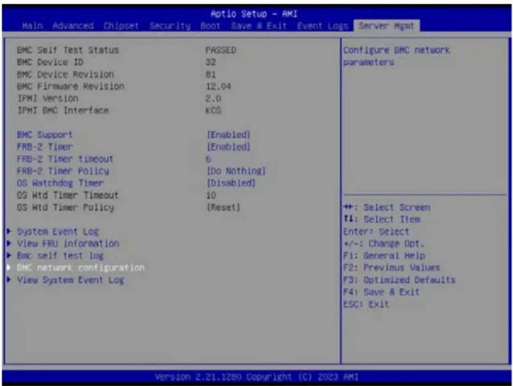
text_image
Aptio Setup - AMI Main Advanced Chipset Security Boot Save & Exit Event Logs Server Mgmt BMC Self Test Status PASSED BMC Device ID 32 BMC Device Revision 81 BMC Firmware Revision 12.04 IPMI Version 2.0 IPMI BMC Interface KCS BMC Support [Enabled] FRB-2 Timer [Enabled] FRB-2 Timer timeout 6 FRB-2 Timer Policy [Do Nothing] OS Watchdog Timer [Disabled] OS Wtd Timer Timeout 10 OS Wtd Timer Policy [Reset] ► System Event Log ► View FRU information ► Bmc self test log ► BMC network configuration ► View System Event Log Configure BMC network parameters ++: Select Screen ↑: Select Item Enter: Select +/-: Change Opt. F1: General Help F2: Previous Values F3: Optimized Defaults F4: Save & Exit ESC: Exit Version 2.21.1280 Copyright (C) 2023 AMI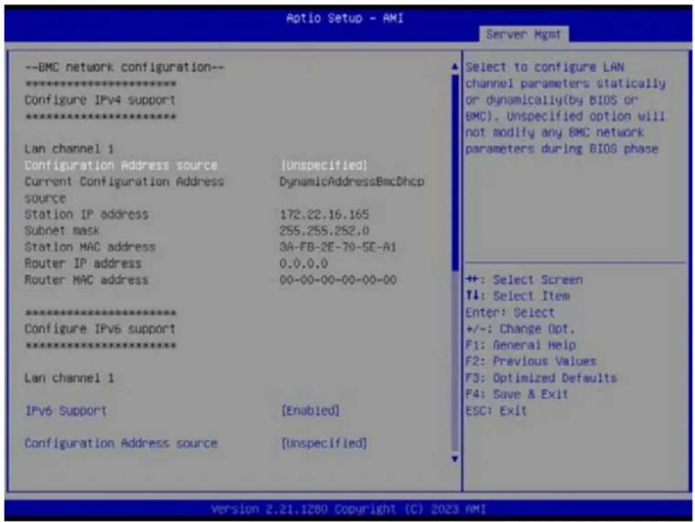
text_image
Aotio Setup - AMI Server Mgmt --BMC network configuration-- ****************** Configure IPv4 support ****************** Lan channel 1 Configuration Address source (Unspecified) Current Configuration Address source DynamicAddressBmcDhcp Station IP address 172.22.16.165 Subnet mask 255.255.252.0 Station MAC address 3A-FB-2E-70-5E-A1 Router IP address 0.0.0.0 Router MAC address 00-00-00-00-00-00-00 ****************** Configure IPv6 support ****************** Lan channel 1 IPv6 Support [Enabled] Configuration Address source (Unspecified) Select to configure LAN channel parameters statically or dynamically(by BIOS or BMC). Unspecified option will not modify any BMC network parameters during BIOS phase +: Select Screen T1: Select Item Enter: Select +/-: Change Opt. F1: General Help F2: Previous Values F3: Optimized Defaults F4: Save & Exit ESC: Exit Version 2.21.1280 Copyright (C) 2023 AMI■ Configuration Address Source
Select to configure LAN channel parameters statically or dynamically (by BMC). The Unspecified option will not modify any BMC network parameters during the BIOS phase.
3.2.8.5 View System Event Log

text_image
Aptio Setup - AMI Main Advanced Chipset Security Boot Save & Exit Event Logs Server Mgmt BMC Self Test Status PASSED BMC Device ID 32 BMC Device Revision 81 BMC Firmware Revision 12.04 IPMI Version 2.0 IPMI BMC Interface KCS BMC Support [Enabled] FRB-2 Timer [Enabled] FRB-2 Timer timeout 6 FRB-2 Timer Policy [Do Nothing] OS Watchdog Timer [Disabled] OS Wtd Timer Timeout 10 OS Wtd Timer Policy [Reset] ► System Event Log ► View FRU information ► BMC self test log ► BMC network configuration ► View System Event Log Press3.2.9 BMC - Setting of WEB Browser

text_image
ADVANTECH Enabling an Intelligent Planet Advantech-BMC Username Password US- English Remember Username Sign out in Choose my password■ User should check the "Station IP address" of BIOS menu (chapter 3.8.4) before logging in the web browser and the URL should begin with "https://"
■ Default user login
Administrator: admin
Password: admin
It is mandatory to change the password for the default user at first successful login. Once the password is changed, login page will be reloaded, enter the username and modified password to login the Browser.
Straight password format policies are enforced on the BMC, the password will need to include at least a capital letter, small capital letter or special characters. The password management policies will also be enforced on the IPMI of the BMC interface.
3.2.9.1 Dashboard Page
OFF state

text_image
Advantech-SMC Business Information SPLC M2.00000000000000000000000000000000000000000000000000000000000000000 Dashboard Default Panel 15 - English SIP Layer Network admin Default Panel Default Panel Default Panel Default Panel Default Panel Default Panel Default Panel Default Panel Default Panel Default Panel Default Panel Default Panel Default Panel Default Panel Default Panel Default Panel Default Panel Default Panel Default Panel Default Panel Default Panel Default Panel Default Panel Default Panel Default Panel Default Panel Default Panel Default Panel Default Panel Default Panel Default Panel Default Panel Default Panel Default Panel- The dashboard page will show power-on hours and access log information only when the toggle button is in the OFF state. The area of power-on hours will keep on accumulating and it will reset to zero when the system is in power-off, and access logs will show all events incurred by various sensors.
ON state

text_image
Advantech-EMC Disease information 10.00 A AVS OR USED MARKED OUT New Online Dashboard 0 d 0 hrs Power On Hours 3 System Logs Main Site Dashboard Sense FRC Information Logo & Images Settings Remodel Control Image Animation Power Control Maintenance Sign-out Today (n) Details system_event 10 events 30 days (n) Details system_event 10 events Sensor Monitoring All sensors are good now! Currently recovered- When the toggle button is in ON state, it will show 'Today & 30 Days' and 'Sensor Monitoring' information.
3.2.9.2 Sensor
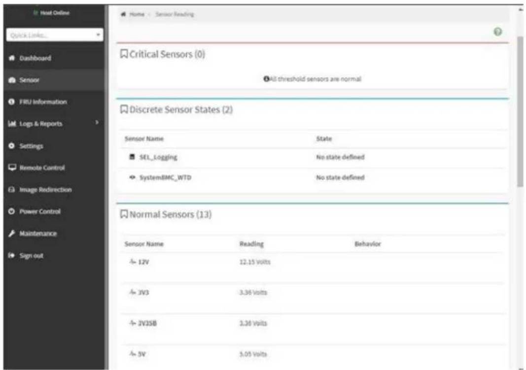
text_image
Host Online Quick Links... Dashboard Sensor FRU Information Logs & Reports Settings Remote Control Image Redirection Power Control Maintenance Sign out Home - Sensor Reading Critical Sensors (0) All threshold sensors are normal Discrete Sensor States (2) Sensor Name State SEL_Logging No state defined SystemBMC_WTD No state defined Normal Sensors (13) Sensor Name Reading Behavior 12V 12.15 volts JV3 3.36 volts JVJSB 3.36 volts 5V 5.05 volts3.2.9.3 FRU Information

text_image
Host Online Quick Links... Dashboard Sensor FRU Information Logs & Reports Settings Remote Control Image Redirection Power Control Maintenance Sign out Available FRU Devices FRU Device ID FRU Device Name Board FRU Chassis Information Board Information Product Information Chassis Information Area 1 Board Information 1 Product Information Area 1 Format Version Area Format Version Language English Chassis Type Other Chassis Part Number Manufacture Date Mon Oct 24 Time 22/00/00 2022 Board Advantech Manufacturer Board Product AJMB-592 Name Board Serial Number Board Part Number Product Information Language English Product Manufacturer Product Name Product Part Number Product Version Product Serial Number Asset Tag■ Shows information of chassis, board or product information of FRU device.
3.2.9.4 LOG & Reports - IPMI Event Log
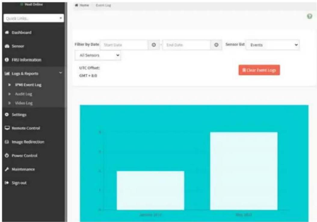
text_image
Host Online Quick Links... Dashboard Sensor FRU Information IM Logs & Reports IPMI Event Log Audit Log Video Log Settings Remote Control Image Redirection Power Control Maintenance Sign out Home Event Log Filter by Date Start Date End Date Sensor list Events All Sensors UTC Offset: GMT + 8:0 Clear Event Logs January 2014 May 20133.2.9.5 LOG & Reports – Audit Log

text_image
Home Audit Log Quick Links... Dashboard Sensor FRU Information Log & Reports IPMI Event Log Audit Log Video Log Settings Remote Control Image Redirection Power Control Maintenance Sign out Filter by Date Start Date End Date Audit Log: 94 out of 94 event entries May 2023 ID: 94 May 16th 2023, 1:32:35 pm AMIEA114B9FBB47 spx_restservice: spx_restservice -- [1193 : 1193 INFO]https Login from IP:172.22.214.181 user:admin - ID: 93 May 16th 2023, 1:29:22 pm AMIEA114B9FBB47 spx_restservice: spx_restservice -- [1193 : 1193 WARNING]https Login Failed from IP:172.22.214.181 user:admin - ID: 92 May 16th 2023, 1:11:24 pm AMIEA114B9FBB47 spx_restservice: spx_restservice -- [1193 : 1193 INFO]HTTPS logout from IP:172.22.16.74 user:admin - ID: 91 May 16th 2023, 1:11:08 pm AMIEA114B9FBB47 adviserd: adviserd -- [1146 : 1163 INFO]KVM logout from IP:172.22.16.74 user:admin - ID: 90 May 16th 2023, 1:10:49 pm AMIEA114B9FBB47 adviserd: adviserd -- [1146 : 1163 INFO]kvm Login from IP:172.22.16.74 user:admin - ID: 89 May 16th 2023, 1:09:29 pm AMIEA114B9FBB47 spx_restservice: spx_restservice -- [1193 : 1193 INFO]https Login from IP:172.22.16.74 user:admin -3.2.9.6 LOG & Reports – Video Log

text_image
Video Log All video event logs Filter by Date Start Date End Date Video Log: 0 out of 0 event entriesThis page will display the video log when video trigger settings is enabled, user can adjust under “‘Setting -> Video Recording -> Auto Video Settings -> Video Trigger Settings” item.
3.2.9.7 Settings
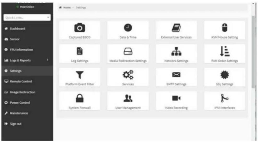
text_image
Captured BSOD Date & Time External User Services KVM Mouse Setting Log Settings Media Redirection Settings Network Settings PAM Order Settings Platform Event Filter Services SMTP Settings SSL Settings System Firewall User Management Video Recording IPMI Interfaces■ Users can access various configuration settings through this page
3.2.9.8 Remote Control
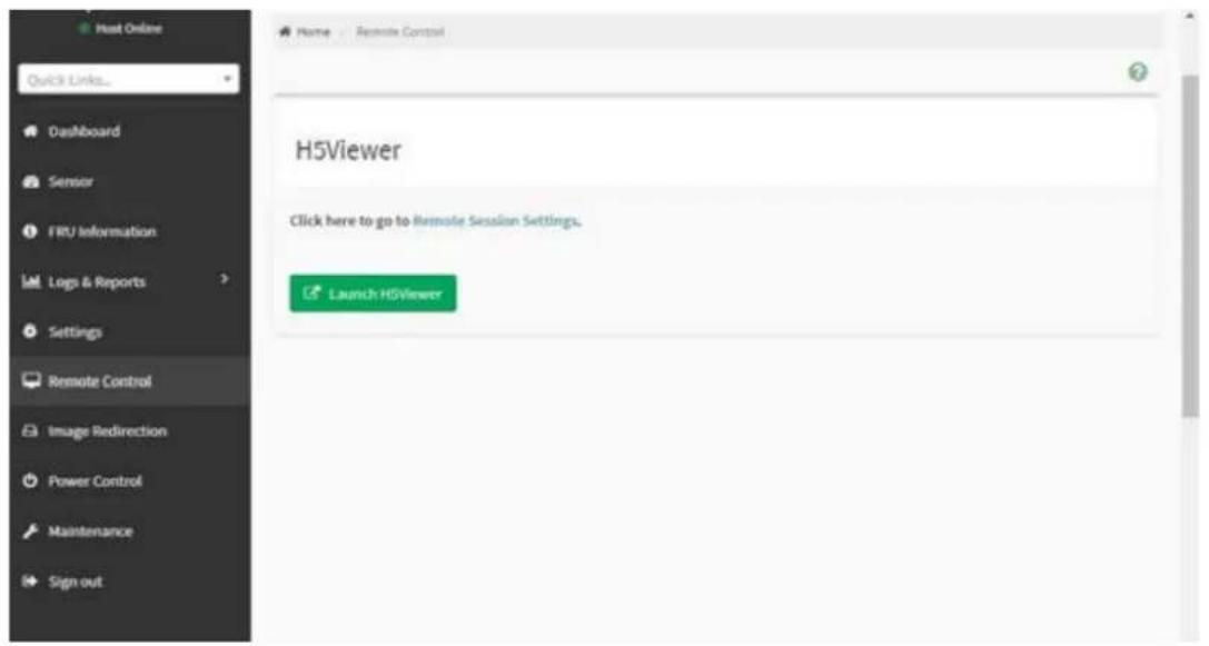
text_image
Host Online Quick Links... Dashboard Sensor FRU Information Logs & Reports Settings Remote Control Image Redirection Power Control Maintenance Sign out Name Remote Control H5Viewer Click here to go to Remote Session Settings. Launch H5ViewerRemote Control – Launch H5viewer

text_image
EVI Shell version 2.00 [5.22] Current running mode 1.1.2 Map: Cannot find required map name. Press ESC in 1 seconds to ship startup.nsh, why other way to continue. SHIELD:3.2.9.9 Image Redirection

text_image
Image Redirection Remote Images US - English Sync Refresh admin Home Image Direction3.2.9.10 Power Control
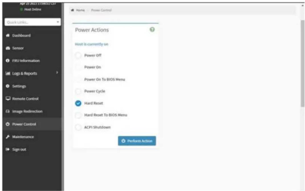
text_image
qpr 20 ADJ11TREST CSF Host Online Quick URL... Dashboard Sensor FRU information Logs & Reports Settings Remote Control Image Redirection Power Control Maintenance Sign out Home - Power Control Power Actions Host is currently on Power Off Power On Power On To BIOS Menu Power Cycle ✓ Hard Reset Hard Reset To BIOS Menu ACPI Shutdown Perform ActionThis page allows the user to view and control the power of the system platform from a remote device.
3.2.9.11 Maintenance
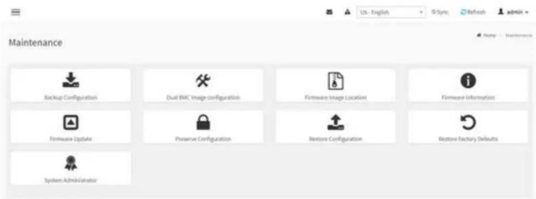
text_image
Maintenance Backup Configuration Dual BMC Image configuration Firmware Image Location Firmware Information Firmware Update Preserve Configuration Restore Configuration Restore Factory Defaults System AdministratorChapter 4
Software Introduction & Service
4.1 Introduction
The mission of Advantech Embedded Software Services is to "Enhance quality of life with Advantech platforms and Microsoft® Windows® embedded technology." We enable Windows® Embedded software products on Advantech platforms to more effectively support the embedded computing community. Customers are freed from the hassle of dealing with multiple vendors (hardware suppliers, system integrators, embedded OS distributors) for projects. Our goal is to make Windows® Embedded Software solutions easily and widely available to the embedded computing community.
4.2 Value-Added Software Services
Software API: An interface that defines the ways by which an application program may request services from libraries and/or operating systems. Provides not only the underlying drivers required but also a rich set of user-friendly, intelligent and integrated interfaces, which speeds development, enhances security and offers add-on value for Advantech platforms. It plays the role of catalyst between developer and solution, and makes Advantech embedded platforms easier and simpler to adopt and operate with customer applications.
4.2.1 Software API
4.2.1.1 Control
GP I/O

natural_image
Blue square icon with a white abstract line and checkmark symbol (no text or numbers)General Purpose Input/Output is a flexible parallel interface that allows a variety of custom connections. It allows users to monitor the level of signal input or set the output status to switch on/off the device. Our API also provide Programmable GPIO, which allows developers to dynamically set the GPIO input or output status.
SMBus

natural_image
Blue square icon with white abstract line and circular elements, no text or symbols present.SMBus is the System Management Bus defined by Intel Corporation in 1995. It is used in personal computers and servers for low-speed system management communications. The SMBus API allows a developer to interface a embedded system environment and transfer serial messages using the SMBus protocols, allowing multiple simultaneous device control.
4.2.1.2 Display
Brightness Control

natural_image
Blue square icon with a white sunburst symbol (no text or numbers)The Brightness Control API allows a developer to access embedded devices and easily control brightness.
Brightness Control

natural_image
Blue square icon with white diagonal line and power symbol (no text or numbers)The Backlight API allows a developer to control the backlight (screen) on/off in embedded devices.
4.2.1.3 Monitor
Watchdog

natural_image
Silhouette of a dog's head and collar against a blue background (no text or symbols)A watchdog timer (WDT) is a device that performs a specific operation after a certain period of time if something goes wrong and the system does not recover on its own. A watchdog timer can be programmed to perform a warm boot (restarting the system) after a certain number of seconds.
Hardware Monitor

natural_image
Blue square icon with white thermometer and propeller symbol (no text)The Hardware Monitor (HWM) API is a system health supervision API that inspects certain condition indexes, such as fan speed, temperature and voltage.
4.2.1.4 Power Saving
CPU Speed

natural_image
Blue square icon with a white gauge scale showing current value and 100-degree scale, no text or symbols beyond the numbers.Makes use of Intel SpeedStep technology to save power consumption. The system will automatically adjust the CPU speed depending on the system loading.
System Throtting
natural_image
Blue square icon with white lightning bolt symbols indicating current flow or wave patterns (no text or numbers)Refers to a series of methods for reducing power consumption in computers by lowering the clock frequency. This API allows the user to adjust the clock from 87.5% to 12.5%.
4.2.2 Software Utility
BIOS Flash
natural_image
Blue square icon with a white integrated circuit chip outline (no text or symbols)The BIOS Flash utility allows customers to update the flash ROM BIOS version, or use it to back up current BIOS by copying it from the flash chip to a file on the customers' disk. The BIOS Flash utility also provides a command line version and an API for fast implementation into customized applications.
Monitoring

natural_image
Blue square icon with a white eye symbol in the center (no text or symbols)Monitoring is a utility for customers to monitor system health, like voltage, CPU and system temperature and fan speed. These items are important to a device, if critical errors occur and are not solved immediately, permanent damage may be caused.
Chapter 5
Chipset Software Installation Utility
5.1 Before You Begin
To facilitate the installation of the enhanced display drivers and utility software, read the instructions in this chapter carefully. The drivers for the AIMB-592 are available online for download from the Advantech support website.
5.2 Introduction
The AMD Chipset Software Installation (CSI) utility installs the Windows INF files that outline to the operating system how the chipset components will be configured. This is needed for the proper functioning of the following features:
Core PCI PnP services
■ Serial ATA interface support
USB 2.0/3.1 support
■ Identification of AMD chipset components in the Device Manager
Note! This utility is used for the following versions of Windows, and it has to be installed before installing all the other drivers:

Windows Server 2019 Standard x64
Windows Server 2016 Standard x64
Note! It is necessary to update all the latest Microsoft hot fix files when using this OS.

5.3 Windows Series Driver Setup
- When enter the website of Advantech, then search product AIMB-592. There is "Chip" driver inside.
WinSvr19 driver for AIMB-592
2023-05-26 Driver Document No.1-5161758611
Related Product:
AIMB-592
Solution:
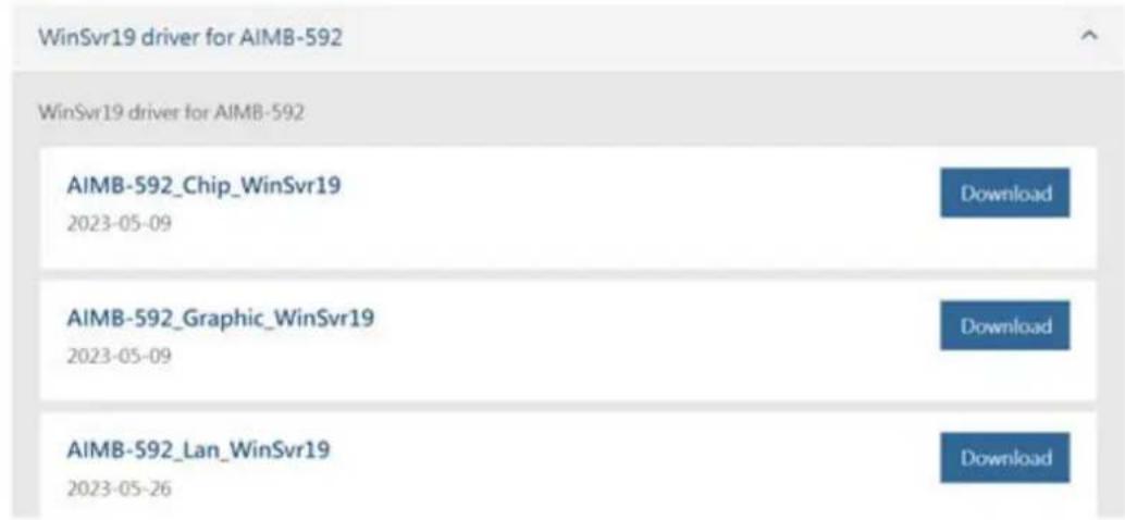
text_image
WinSvr19 driver for AIMB-592 WinSvr19 driver for AIMB-592 AIMB-592_Chip_WinSvr19 2023-05-09 Download AIMB-592_Graphic_WinSvr19 2023-05-09 Download AIMB-592_Lan_WinSvr19 2023-05-26 DownloadChapter 6
LAN Configuration
6.1 Introduction
AIMB-592 features dual 2.5 Gigabit Ethernet LANs via dedicated PCI Express x1 lanes (Intel i226-LM for LAN1&2) that supports 10/100/1000/2500 Mbps Ethernet speed and dual 10 Gigabit Ethernet LANs via dedicated PCI Express x4 lanes (Intel X550-AT for LAN3&4) that supports 100/1000/10000 Mbps Ethernet speed.
6.2 Windows Series Driver Setup
When enter the website of Advantech, then search product AIMB-592. There is "LAN" driver inside.
WinSvr19 driver for AIMB-592
2023-05-26 Driver Document No.1-5161758611
Related Product:
AIMB-592
Solution:

text_image
WinSvr19 driver for AIMB-592 WinSvr19 driver for AIMB-592 AIMB-592_Chip_WinSvr19 2023-05-09 Download AIMB-592_Graphic_WinSvr19 2023-05-09 Download AIMB-592_Lan_WinSvr19 2023-05-26 DownloadAppendix A
Pin Assignments
A.1 CMOS Clear Jumper (JCMOS1)
Table A.1: CMOS Clear Jumper (JCMOS1)
| Function Jumper Setting | |
| Keep COMS Data (Default) |  |
| Clear CMOS Date | 1 2 3 |
| Pin Signal Pin Definition | |
| 1 +V1.5_RTC_JMP | |
| 2 +V1.5_RTC | |
| 3 GND | |
A.2 Front Panel1 + Front Panel2 header (JFP1+JFP2)
Table A.2: Front Panel1 + Front Panel2 header (JFP1+JFP2)
| Pin Signal Pin Definition Pin Signal Pin Definition | ||
| 1 FRP_SPK2 7 FRP_SPK3 | ||
| 2 +V3.3 8 HWM_SMB_DATA | ||
| 3 FP_PWR_BTN_S# 9 FP_RST_BTN_S# | ||
| 4 | 10 | FRP_SPK4 |
| 5 SATA_LED# | 11 | HWM_SMB_CLK |
| 6 GND | 12 | GND |
A.3 Case open pin header (JCASE1)
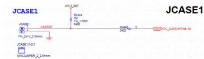
text_image
JCASE1 JCASE1 PH_2x1V_2.54mm JCASE1(1-2)1 MINJUMPER_2.04mm CASSOR AV3 3_BAT R4444 1M 1% 1/15W 0402 0402 0 EC_CASEOPEN8 83 JCASE1Table A.3: Case open pin header (JCASE1)
| Pin | Signal |
| 1 | CASEOP |
| 2 | GND |
A.4 ATX 12V IN connector (ATX12V1/ ATX12V2)ATX/ AT Mode Selection (PSON1)

text_image
CPU0 ATX12V1 +V12_8P_0 5 6 7 8 ATX_4X2V_4.2mm DIMM +V12_8P_0 5 6 7 8 ATX12V2 ATX_4X2V_4.2mm 1 2 3 4Table A.4: ATX 12V IN connector (ATX12V1/ ATX12V2)ATX/AT Mode Selection (PSON1)
| Pin Signal Pin Signal |
| 1 GND 5 +V12_8P_0 |
| 2 GND 6 +V12_8P_0 |
| 3 GND 7 +V12_8P_0 |
| 4 GND 8 +V12_8P_0 |
A.5 ATX 24pin IN connector (ATXPWR1)
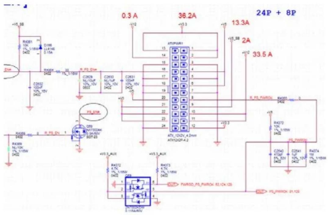
text_image
0.3 A 36.2A 13.3A 2A 33.5 A R4301 10K 1% L/18W D402 C196 LL414E 0.15A R4304 2402 R.PS_DIN C2629 NL/10UF 10% 10V 0603 C2630 NL/1UF 10% 10V D402 C2631 100m 10% 10V D402 R.PS_PWRON R4302 2402 R4370 10K 1% L/18W D402 R4371 1UF 10% 10V D402 C2540 470pF 5% 52V D402 C2541 1UF 10% 10V D402 R4374 1M 1% L/18W D402 R4372 4.7k 1% L/18W D402 R4373 4.7k 1% L/18W D402 R4374/PSPWROK 63.12x.12s R4375/PSPWROK 21.12sTable A.5: ATX 24pin IN connector (ATXPWR1)
| Pin Signal Pin Signal | ||
| 1 +V3.3 13 +V3.3 | ||
| 2 +V3.3 14 -V12 | ||
| 3 GND 15 GND | ||
| 4 +V5 16 PS_ON# | ||
| 5 GND 17 GND | ||
| 6 +V5 18 GND | ||
| 7 GND 19 GND | ||
| 8 PWR_OK 20 -V5 | ||
| 9 +V5_SB 21 +V5 | ||
| 10 | +V12 | 22 +V5 |
| 11 | +V12 | 23 +V5 |
| 12 | +V3.3 24 GND | |
A.6 GPIO header (GPIO1)
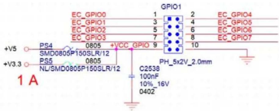
text_image
GPIO1 EC_GPIO0 1 2 EC_GPIO4 EC_GPIO1 3 4 EC_GPIO5 EC_GPIO2 5 6 EC_GPIO6 EC_GPIO3 7 8 EC_GPIO7 +V5 PS4 0805 +VCC GPIO 9 10 SMD0805P150SLR/12 PS5 0805 NL/SMD0805P150SLR/12 PH_5x2V_2.0mm C2538 100nF 10%_16V 0402 +V3.3 1 ATable A.6: GPIO header (GPIO1)
| Pin Signal Pin Signal | ||
| 1 EC_GPIO0 | 2 | EC_GPIO4 |
| 3 EC_GPIO1 | 4 | EC_GPIO5 |
| 5 EC_GPIO2 | 6 | EC_GPIO6 |
| 7 EC_GPIO3 | 8 | EC_GPIO7 |
| 9 +V5 10 GND | ||
A.7 EC programing header (SCN1)
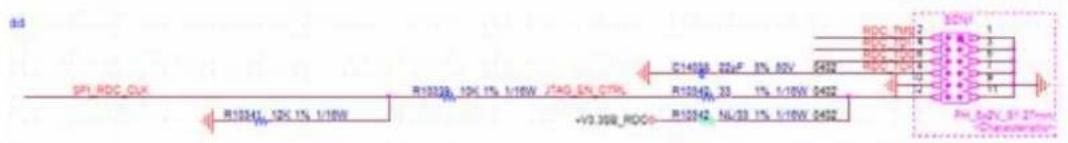
text_image
SP1:RDC_CUX R13200 10K 1% 1/16W JTAG_EN_CTR +V3.308_ROD0 R13241 10K 1% 1/16W R13200 10K 1% 1/16W 240 EN_CTR C14598 22uF 8% 30V 0492 R13242 33 1% 1/16W 0492 R13242 NL/33 1% 1/16W 0492 R13242 NL/33 1% 1/16W 0492 RDC_TMU2 RDC_1001 4 RDC_1002 4 RDC_1003 4 RDC_1004 4 RDC_TMU7 RDC_1005 4 RDC_1006 4 RDC_1007 4 RDC_1008 4 RDC_1009 4 RDC_1010 4 RDC_1011 4 RDC_1012 4 RDC_1013 4 RDC_1014 4 RDC_1015 4 RDC_1016 4 RDC_1017 4 RDC_1018 4 RDC_1019 4 RDC_1020 4 RDC_1021 4 RDC_1022 4 RDC_1023 4 RDC_1024 4 RDC_1025 4 RDC_1026 4 RDC_1027 4 RDC_1028 4 RDC_1029 4 RDC_1030 4 RDC_1031 4 RDC_1032 4 RDC_1033 4 RDC_1034 4 RDC_1035 4 RDC_1036 4 RDC_1037 4 RDC_1038 4 RDC_1039 4 RDC_1040 4 RDC_1041 4 RDC_1042 4 RDC_1043 4 RDC_1044 4 RDC_1045 4 RDC_1046 4 RDC_1047 4 RDC_1048 4 RDC_1049 4 RDC_1050 4 RDC_1051 4 RDC_1052 4 RDC_1053 4 RDC_1054 4 RDC_1055 4 RDC_1056 4 RDC_1057 4 RDC_1058 4 RDC_1059 4 RDC_1060 4 RDC_1061 4 RDC_1062 4 RDC_1063 4 RDC_1064 4 RDC_1065 4 RDC_1066 4 RDC_1067 4 RDC_1068 4 RDC_1069 4 RDC_1070 4 RDC_1071 4 RDC_1072 4 RDC_1073 4 RDC_1074 4 RDC_1075 4 RDC_1076 4 RDC_1077 4 RDC_1078 4 RDC_1079 4 RDC_1080 4 RDC_1081 4 RDC_1082 4 RDC_1083 4 RDC_1084 4 RDC_1085 4 RDC_1086 4 RDC_1087 4 RDC_1088 4 RDC_1089 4 RDC_1090 4 RDC_1091 4 RDC_1092 4 RDC_1093 4 RDC_1094 4 RDC_1095 4 RDC_1096 4 RDC_1097 4 RDC_1098 4 RDC_1099 4 RDC_1100 4Table A.7: EC programing header (SCN1)
| Pin Signal Pin Signal |
| 1 GND 2 RDC_TMS |
| 3 GND 4 RDC_TDI |
| 5 GND 6 RDC_TDO |
| 7 GND 8 RDC_TCK |
| 9 GND 10 GND |
| 11 GND 12 SPI_RDC_CLK |
A.8 System FAN Connector (SYSFAN1/SYSFAN2/SYSFAN3/SYSFAN4)

text_image
3 A +V3.3 R4280 4.7K 1% 1/16W 0402 1 2 3 4 R4283 100 0402 +V5 +V6 R4281 10K 1% 1/16W 0402 D150 RB75 1540 0.2A D151 RB75 1540 0.2A C2572 100uF 10% 26V 0402 C2573 22uF 20% 26V 0905 D149 RB751540 0.2A R4277 4.7K 1% 1/16W 0402 R4278 0402 I EYE1_FAN_PWM_IN TI_EN74AHCT1G-125OCKR R4284 0402 NL/100 1% 1/16W RYBRAN1 54mmTable A.8: System FAN Connector (SYSFAN1)
| Pin Signal | |
| 1 | GND |
| 2 | +V12 |
| 3 | SYS1_FAN_TACH |
| 4 | SYS_FAN1_PWM |
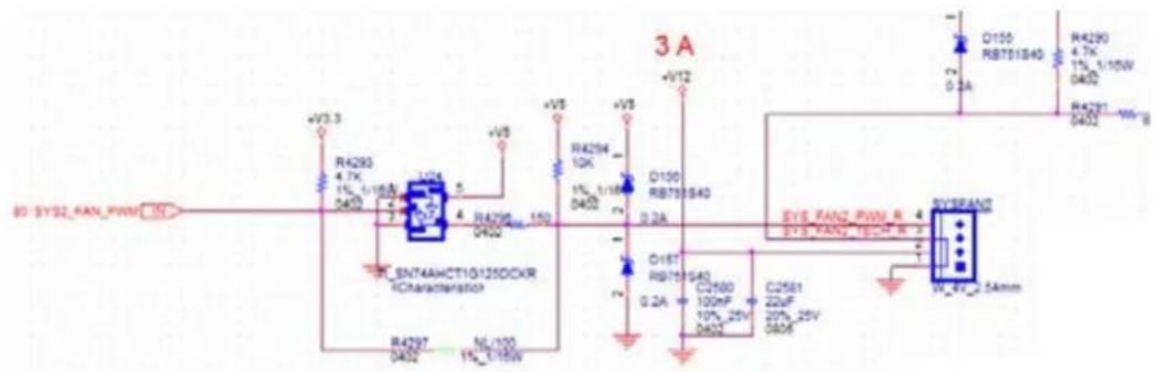
text_image
3 A +V3.3 R4293 4.7K 1% 1/160V 0400 SN74AHCT1G125DCXR 1Characterization R4297 0402 ML/100 1%_0155W +V5 R4298 10K 4 R4299 150 0402 +V5 R4294 10K 1% 1/160V 0400 O100 RB755S40 0.2A O18T RB755S40 0.2A C2560 100mF 10%_25V 0402 C2561 22uF 25%_25V 0406 EYS RANG_PWM_R EYS RANG_160M_R EYS RANG_25mmTable A.9: System FAN Connector (SYSFAN2)
| Pin Signal |
| 1 GND |
| 2 +V12 |
| 3 SYS2_FAN_TACH |
| 4 SYS2_FAN_PWM |

text_image
SYS3 FAN_PWMOUT R951 0 0402 5% SYS3 FAN_PWMOUT_R SYS3 FAN_SPEED 4 SYS3 FAN_OUT 3 C804 C805 10uF 100nF 16V 10%_16V 0805 W_4V_2.54mmTable A.10: System FAN Connector (SYSFAN3)
| Pin Signal |
| 1 GND |
| 2 SYS3_FAN_OUT |
| 3 SYS3_FAN_SPEED |
| 4 SYS3_FAN_PWMOUT |
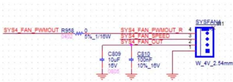
text_image
SYS4_FAN_PWMOUT R958 0 0402 5%_1/16W SYS4_FAN_PWMOUT_R 4 SYS4_FAN_SPEED 3 SYS4_FAN_OUT 2 C809 C810 10uF 100nF 16V 10%_16V 0805 W_4V_2.54mmTable A.11: System FAN Connector (SYSFAN4)
| Pin Signal |
| 1 GND |
| 2 SYS4_FAN_OUT |
| 3 SYS4_FAN_SPEED |
| 4 SYS4_FAN_PWMOUT |
A.9 CPU FAN connector (CPUFAN1)
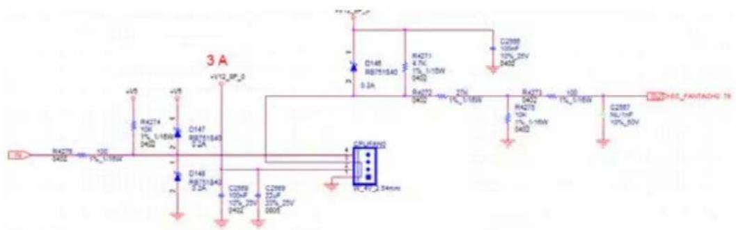
text_image
3 A +V12 SP-0 D148 RB751640 0.2A R42T1 4.7K 1% L/16W 0402 C2988 10kV 10% 25V 5402 D42T2 10kV 1% L/16W 0402 R42T3 10kV 1% L/16W 1% L/16W C2987 10kV 10% 25V 5402 CPU/Rand0 RL_47_2.54mmTable A.12: CPU FAN connector (CPUFAN1)
| Pin Signal |
| 1 GND |
| 2 +V12_8P_0 |
| 3 EC_FANTACH0 |
| 4 EC_CPU_PWM |
A.10 Serial GPIO (SGPIO1)

text_image
R_SGPIO2_CLK_BUF1 R_SGPIO2_LOAD_BUF1 R_SGPIO2_DATAOUT_BUF1 SGPIO1 1 3 4 5 PH_5x1V_2.54mm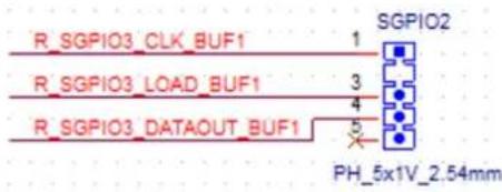
text_image
R_SGPIO3_CLK_BUF1 R_SGPIO3_LOAD_BUF1 R_SGPIO3_DATAOUT_BUF1 SGPIO2 1 3 4 5 PH_5x1V_2.54mmTable A.13: Serial GPIO (SGPIO1)
| Pin Signal |
| 1 R_SGPIO_CLK_BUF1 |
| 2 |
| 3 R_SGPIO_LOAD_BUF1 |
| 4 R_SGPIO_DATAOUT_BUF1 |
| 5 |
A.11 System Error Led wafer (BMC\_SYSLED1)

text_image
SYS_LED1 WB_2V_2.5mm 1 2 R296 220 1% 1/16W +V3.3_AUX SYS_LED# 83 SYS_ERR_LED IN Q75 NX7002AK 0.3A/60V SOT-23Table A.14: System Error Led wafer (BMC_SYSLED1)
| Pin Signal |
| 1 +V3.3_AUX |
| 2 SYS_LED# |
A.12 PMBus wafer (PMBUS1)
PMBUS CONN.

text_image
BUS CONN. +V3.3_AUX R285 NL/4.7K 1% 1/16W 0402 R283 NL/4.7K 1% 1/16W 0402 R284 4.7K 1% 1/16W 0402 +V3.3_AUX B78 33_100MHz 3A 0603 +V3.3 B79 NL/33_100MHz 3A 0603 A101-2.82 T5 PMBUS_SMB_CLK T5 PMBUS_SMB_DATA IN SI PMBUS_SMB_CLK PMBUS_SMB_DATA PMBUS_SW_ALERT# PMBUS1 H1 1 2 3 4 5 H2 WB_5V_2.54mmTable A.15: PMBus wafer (PMBUS1)
| Pin Signal |
| 1 PMBUS_SMB_CLK |
| 2 PMBUS_SMB_DATA |
| 3 PMBUS_SW_ALERT# |
| 4 GND |
| 5 +V3.3_AUX |
A.13 HW SMBUS (SMBUS1)
SMBUS CONN.

text_image
CONN. 75,108 HWM_SMB_CLK 75,108 HWM_SMB_DATA IN BI +V3 3_AUX R4387 NL/4.7K 1% 1/16W 0402 R4388 NL/4.7K 1% 1/16W 0402 B80 33_100MHz 3A D503 +V5_SMBUS SMBUS1 WB_4V_2.5mm 1 2 3 4Table A.16: HW SMBUS (SMBUS1)
| Pin Signal |
| 1 +V5 |
| 2 HWM_SMB_CLK |
| 3 HWM_SMB_DATA |
| 4 GND |
A.14 Front Panel3 (JFP3)

text_image
+V5_SB R290 220 PWRLED 0402 5%_1/16W FP_PWR_BTN_S# JFP3 3 2 1 WB_3V_2.0mmTable A.17: Front Panel3 (JFP3)
| Pin Signal |
| 1 FP_PWR_BTN_S# |
| 2 GND |
| 3 +V5_SB |
A.15 Graphics Card 12V slot (SLOT12V1)

text_image
SLOT 4P 33.5 A 5 SLOT12V1 1 6 2 7 3 8 4 AFX_42V_4.2mm +V12 C2044 100nF 10% 25V 0400° PN: 1653007657-01Table A.18: Graphics Card 12V slot (SLOT12V1)
| Pin Signal Pin Signal |
| 1 +V12 5 GND |
| 2 +V12 6 GND |
| 3 +V12 7 GND |
| 4 GND 8 GND |
ADVANTECH
Enabling an Intelligent Planet
www.advantech.com
Please verify specifications before quoting. This guide is intended for reference purposes only.
All product specifications are subject to change without notice.
No part of this publication may be reproduced in any form or by any means, electronic, photocopying, recording or otherwise, without prior written permission of the publisher.
All brand and product names are trademarks or registered trademarks of their respective companies.
© Advantech Co., Ltd. 2023