99-7612B - Kit d'installation auto AXESS - Free user manual and instructions
Find the device manual for free 99-7612B AXESS in PDF.

User questions about 99-7612B AXESS
0 question about this device. Answer the ones you know or ask your own.
Ask a new question about this device
Download the instructions for your Kit d'installation auto in PDF format for free! Find your manual 99-7612B - AXESS and take your electronic device back in hand. On this page are published all the documents necessary for the use of your device. 99-7612B by AXESS.
USER MANUAL 99-7612B AXESS
INSTALLATION INSTRUCTIONS FOR PART 99-7612
U.S. PATENT # D719,560
APPLICATIONS
Nissan Murano 2003-2007 99-7612A, 99-7612B
KIT FEATURES
• ISO DIN radio provision with pocket
• ISO DDIN radio provision
• 7612A-Coated with brushed aluminum look
• 7612B-Painted matte black
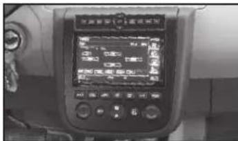
text_image
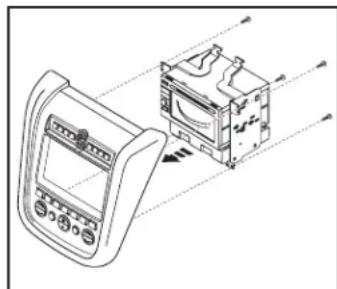
Control panel display showing a digital interface with Chinese text and measurement data, likely from an industrial or control system.KIT COMPONENTS
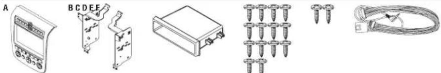
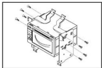
• A) Radio housing • B) Radio housing brackets • C) Pocket • D) (14) #8 x 3/8" Phillips screws
• E) (2) #8 x 1/2" Phillips screws • F) 7612 Wire harness
natural_image
Illustration of various electronic components including a display, panel, oscilloscope, screw rack, and cable (no text or symbols present)WIRING & ANTENNA CONNECTIONS (sold separately)
Wiring Harness: • 70-7550 - 1995-up Nissan • 70-7551 - 1995-up Nissan amp integration Antenna Adapter: • 40-NI11 - Nissan
TOOLS REQUIRED
- Panel removal tool - Phillips screwdriver - Socket wrench
Dash Disassembly
- Nissan Murano 2003-2007 (without OE NAV)* .....2-3
*Note: This kit will work in NAV models, but you will lose the OE NAV controls, and voice prompts.
Kit Assembly
- ISO DIN radio provision with pocket....3-4
- ISO DDIN radio provision 4-5
Wiring Instructions....5
CAUTION: Metra recommends disconnecting the negative battery terminal before beginning any installation. All accessories, switches, and especially air bag indicator lights must be plugged in before reconnecting the battery or cycling the ignition.
NOTE: Refer to the instructions included with the aftermarket radio.

99-7612
Dash Disassembly
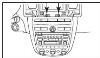
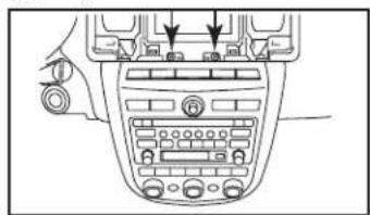
- Unclip and remove the vent panel above the radio. (Figure A)
- Remove (2) Phillips screws exposed behind the vent panel. (Figure B)
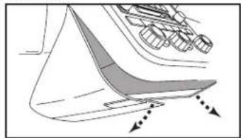
- Unclip and remove the lower trim panel around the bottom of the radio panel. (Figure C)

natural_image
Line drawing of a car dashboard with steering wheel and control panel (no text or symbols)(Figure A)
natural_image
Diagram of a car infotainment system with control panel and directional arrows (no text or labels)(Figure B)

natural_image
Diagram of a boat hull with arrows indicating direction (no text or labels)(Figure C) (Figure D)
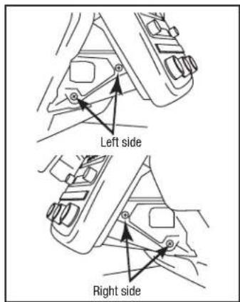
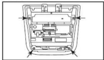
- Remove (2) Phillips screws on each side of the radio chassis exposed behind the lower trim panel. (Figure D)
- Remove radio/climate control assembly from the sub dash.
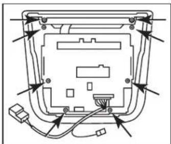
- Remove (4) Phillips screws securing the radio chassis to the factory
text_image
Left side Right sideradio trim panel. Lift up slightly and proceed to step 7. (Figure E)
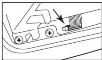
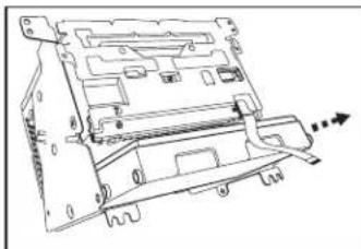
- Unlock the connector on the switch panel and remove the cable joining the chassis and switch panel. (Figure F)
Continued on next page
natural_image
Pure mechanical component diagram without any text, numbers, or symbols(Figure F)

natural_image
Technical line drawing of a mechanical or electronic component with internal compartments and mounting holes (no text or symbols)(Figure E)
99-7612
Dash Disassembly Kit Assembly
- Remove the climate module from radio chassis assembly. (Figure G)
Note: The climate module will be reused in kit assembly.
- Remove (1) Phillip screw, securing the white flat 16-pin connector to the switch panel, then remove the connector.
Note: This connector will be reused in kit assembly.
- Remove (8) Phillips screws securing the switch panel to the radio trim panel. (Figure H)
Note: The radio trim panel will be reused in kit assembly.
Continue to kit assembly
natural_image
Technical line drawing of a computer drive chassis with mounting holes and internal components (no text or symbols)(Figure G)

natural_image
Diagram of a device rear panel with wiring and connectors (no text or labels)(Figure H)
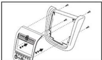
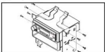
ISO DIN radio provision with pocket
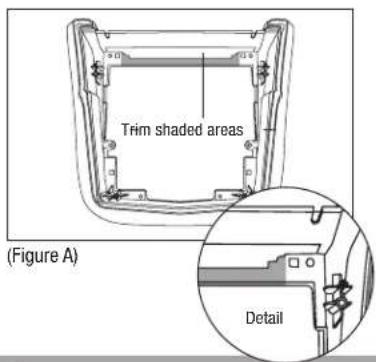
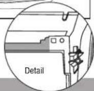
- Trim the shaded areas from the factory radio trim panel. (Figure A) Do not cut the locator and screw hole off as they will be necessary to mount the 99-7612 radio housing. (See detail)
- Attach the 99-7612 radio housing to the radio trim panel using (4) supplied 3/8" Phillips screws. (Figure B)
text_image
Trim shaded areas (Figure A) Detail- Mount the radio housing brackets to the aftermarket radio with the screws supplied with the radio. (Figure C)
- Mount the pocket to the radio/ bracket assembly using (4) 3/8" Phillips screws supplied with the kit. (Figure C)
Continued on next page
natural_image
Technical line drawing of a device with internal components and directional arrows (no text or symbols)(Figure B)

text_image
Technical diagram of a mechanical device with labeled components and directional arrows indicating flow or movement.(Figure C)

99-7612
Kit Assembly
ISO DIN radio provision with pocket (continued)
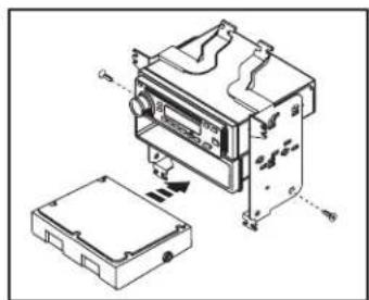
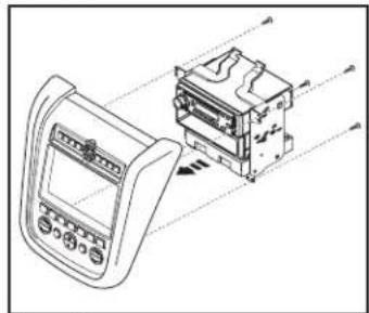
- Mount the climate module to the radio/bracket assembly using (2) 3/8" Phillips screws supplied with the kit. (Figure D)
- Plug the white flat 16-pin connector, removed in disassembly, into the 99-7612.
- Mount the radio/pocket/climate assembly to the radio trim panel using (4) 3/8" Phillips screws supplied with the kit. (Figure E)
- Locate the factory wiring harness and antenna plug in the dash. Metra recommends using the proper mating adapters from Metra and/or AXXESS.
- Follow the wiring instructions in this manual and reassemble dash in reverse order of disassembly.
natural_image
Technical diagram of an electronic device with housing and internal components, showing no text or symbols(Figure D)

natural_image
Technical line drawing of a device with an open panel and internal components, no visible text or symbols(Figure E)
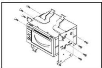
ISO DDIN radio provision
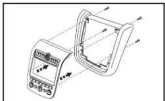
- Trim the shaded areas from the factory radio trim panel. (Figure A) Do not cut the locator and screw hole off as they will be necessary to mount the 99-7612 radio housing. (See detail)
- Attach the 99-7612 radio housing to the radio trim panel using (4) supplied 3/8" Phillips screws. (Figure B)

text_image
Trim shaded areas(Figure A)
- Slide the ISO DDIN aftermarket radio into the radio housing brackets and secure with screws supplied with the radio. (Figure C)
Continued on next page
natural_image
Technical line drawing of a handheld electronic device with control panel and display (no text or symbols)(Figure B)
text_image
Technical diagram of a microwave oven with labeled components and airflow indicators(Figure C)

99-7612
Kit Assembly Wiring Instructions
ISO DDIN radio provision (continued)
- Mount the climate module to the radio/bracket assembly using (2) 3/8" Phillips screws supplied with the kit. (Figure D)
- Plug the white flat 16-pin connector, removed in disassembly, into the 99-7612.
- Mount the radio/climate assembly to the radio trim panel using (4) 3/8" Phillips screws supplied with the kit. (Figure E)
- Locate the factory wiring harness in the dash. Metra recommends using the proper mating adapter from Metra or AXXESS. Re-connect the negative battery terminal and test the radio for proper operation.
- Follow the wiring instructions in this manual and reassemble dash in reverse order of disassembly.

natural_image
Technical line drawing of an electronic device with a box and internal components (no text or symbols)(Figure D)

natural_image
Technical line drawing of a device with an internal component and directional arrows indicating motion (no text or symbols)(Figure E)
From the included 7612 harness:
- Plug the Black 16-way connector into the 99-7612.
- Plug the Black 12-way connector into the 99-7612.
- Plug the White 16-way connector into the factory harness.
Driver Information Center Button Control Note:
The Metra kit button layout does not provide the MAINT or the E/M buttons from the factory setup. MAINT button on the 99-7612 is accessed by pressing the DAY/NIGHT and HOUR buttons simultaneously. The E/M button is done by pressing PREV and MIN simultaneously.
Additional 12-pin harness (ASWC-1)
- This 12-pin harness is to be used in conjunction with the ASWC-1 (not included). Please refer to the ASWC-1 instructions for programming.
Metra
99-7612
Notes
Metra
99-7612
Notes

INSTALLATION INSTRUCTIONS FOR PART 99-7612


KNOWLEDGE IS POWER
Enhance your installation and fabrication skills by corriling in the most recognized and respected.
mobile electronics school in our industry.
Log onto www.installerinstitute.com or call
600-334-6782 for more information and take steps toward a better tomorrow.

Metra recommends MECP
certified technicians

U.S. PATENT # D719,560
APLICACIONES
Nissan Murano 2003-2007 99-7612A, 99-7612B
CARACTERÍSTICAS DEL KIT
text_image
Control panel display showing a digital interface with Chinese text and measurement data, likely from an industrial or transportation system.COMPONENTES DEL KIT
natural_image
Line drawing of a car dashboard with steering wheel and control panel (no text or symbols)(Figura A)
natural_image
Top-down view of a car infotainment device showing mode dial, buttons, and control panel (no text or labels visible)(Figura B)
natural_image
Diagram of a boat hull with arrows indicating direction (no text or symbols)(Figura C) (Figura D)
natural_image
Pure mechanical component diagram without any text, numbers, or symbols(Figura F)
natural_image
Technical diagram of a device interior with internal compartments and mounting points (no text or labels)(Figura E)

99-7612
natural_image
Technical line drawing of a mechanical device with no visible text or symbols(Figura G)
natural_image
Diagram of a device rear panel with cable and connectors, no text or symbols present(Figura H)
natural_image
Technical line drawing of a device with internal components and directional arrows (no text or symbols)(Figura B)
text_image
Technical diagram of a mechanical device with labeled components and directional arrows indicating flow or movement.(Figura C)
Ensamble del kit
natural_image
Technical diagram of an electronic device with housing and internal components, showing no text or symbols(Figura D)
natural_image
Technical line drawing of a device with an open panel and internal components, no visible text or symbols(Figura E)
natural_image
Technical line drawing of a handheld electronic device with control panel and display (no text or symbols)(Figura B)
text_image
Technical diagram of a microwave oven with labeled components and airflow indicators(Figura C)
natural_image
Technical line drawing of an electronic device with a box and internal components, showing no text or symbols.(Figura D)
natural_image
Technical line drawing of a device with an open box and internal components, no visible text or symbols(Figura E)