
XG-NV6XU - Projector SHARP - Free user manual and instructions
Find the device manual for free XG-NV6XU SHARP in PDF.
User questions about XG-NV6XU SHARP
0 question about this device. Answer the ones you know or ask your own.
Ask a new question about this device
Download the instructions for your Projector in PDF format for free! Find your manual XG-NV6XU - SHARP and take your electronic device back in hand. On this page are published all the documents necessary for the use of your device. XG-NV6XU by SHARP.
USER MANUAL XG-NV6XU SHARP
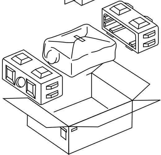
For your assistance in reporting the loss or theft of your Color LCD Projector, please record the Serial Number located on the bottom of the projector and retain this information. Before recycling the packaging, please be sure that you have checked the contents of the carton thoroughly against the list of "Supplied Accessories" on page 10.
Model No.: XG-NV6XU
Serial No.:
There are two important reasons for prompt warranty registration of your new SHARP LCD Projector, using the REGISTRATION CARD packed with the projector.
1. WARRANTY
This is to assure that you immediately receive the full benefit of the parts, service and labor warranty applicable to your purchase.
2. CONSUMER PRODUCT SAFETY ACT
To ensure that you will promptly receive any safety notification of inspection, modification, or recall that SHARP may be required to give under the 1972 Consumer Product Safety Act, PLEASE READ CAREFULLY THE IMPORTANT "LIMITED WARRANTY" CLAUSE. U.S.A. ONLY
WARNING: High brightness light source. Do not stare into the beam of light, or view directly. Be especially careful that children do not stare directly into the beam of light.
WARNING: To reduce the risk of fire or electric shock, do not expose this product to rain or moisture.

CAUTION
RISK OF ELECTRIC SHOCK. DO NOT REMOVE SCREWS EXCEPT SPECIFIED USER SERVICE SCREW.

CAUTION: TO REDUCE THE RISK OF ELECTRIC SHOCK, DO NOT REMOVE COVER. NO USER-SERVICEABLE PARTS EXCEPT LAMP UNIT. REFER SERVICING TO QUALIFIED SERVICE PERSONNEL.

The lightning flash with arrowhead symbol, within an equilateral triangle, is intended to alert the user to the presence of uninsulated "dangerous voltage" within the product's enclosure that may be of sufficient magnitude to constitute a risk or electric shock to persons.

The exclamation point within a triangle is intended to alert the user to the presence of important operating and maintenance (servicing) instructions in the literature accompanying the product.
WARNING: FCC Regulations state that any unauthorized changes or modifications to this equipment not expressly approved by the manufacturer could void the user's authority to operate this equipment. U.S.A. ONLY
INFORMATION
This equipment has been tested and found to comply with the limits for a Class A digital device, pursuant to Part 15 of the FCC Rules. These limits are designed to provide reasonable protection against harmful interference when the equipment is operated in a commercial environment. This equipment generates, uses, and can radiate radio frequency energy and, if not installed and used in accordance with the operation manual, may cause harmful interference to radio communications. Operation of this equipment in a residential area is likely to cause harmful interference, in which case the user will be required to correct the interference at his own expense. U.S.A. ONLY
The enclosed computer cable must be used with the device. The cable is provided to ensure that the device complies with FCC Class A verification.
Electrical energy can perform many useful functions. This product has been engineered and manufactured to ensure your personal safety. But IMPROPER USE CAN RESULT IN POTENTIAL ELECTRICAL SHOCK OR FIRE HAZARD. In order not to defeat the safeguards incorporated into this LCD Projector, observe the following basic rules for its installation, use and servicing. For your own protection and reliable usage of your LCD Projector, please be sure to read these "Important Safeguards" carefully before use.
1. Read Instructions
All the safety and operating instructions should be read before the product is operated.
2. Retain Instructions
The safety and operating instructions should be retained for future reference.
3. HeedWarnings
All warnings on the product and in the operating instructions should be adhered to.
4. Follow Instructions
All operating and use instructions should be followed.
5. Cleaning
Unplug this product from the wall outlet before cleaning. Do not use liquid cleaners or aerosol cleaners. Use a damp cloth for cleaning.
6. Attachments
Do not use attachments not recommended by the product manufacturer as they may cause hazards.
7. Water and Moisture
Do not use this product near water-for example, near a bathtub, wash bowl, kitchen sink, or laundry tub; in a wet basement; or near a swimming pool; and the like.
8. Accessories
Do not place this product on an unstable cart, stand, tripod, bracket, or table. The product may fall, causing serious injury to a child or adult, and serious damage to the product. Use only with a cart, stand, tripod, bracket, or table recommended by the manufacturer, or sold with the product. Any mounting of the product should follow the manufacturer's instructions, and should use a mounting accessory recommended by the manufacturer.
9. Transportation
A product and cart combination should be moved with care. Quick stops, excessive force, and uneven surfaces may cause the product and cart combination to overturn.

10. Ventilation
Slots and openings in the cabinet are provided for ventilation to ensure reliable operation of the product and to protect it from overheating. The openings should never be covered or blocked by placing the product on a bed, sofa, rug, or other similar surface. This product should not be placed in a built-in installation such as a bookcase or rack unless proper ventilation is provided or the manufacturer's instructions have been adhered to.
11. Power Sources
This product should be operated only from the type of power source indicated on the marking label. If you are not sure of the type of power supply to your home, consult your product dealer or local power company. For products intended to operate from battery power, or other sources, refer to the operating instructions.
12. Grounding or Polarization
This product is equipped with a three-wire grounding-type plug, a plug having a third (grounding) pin. This plug will only fit into a grounding-type power outlet. This is a safety feature. If you are unable to insert the plug into the outlet, contact your electrician to replace your obsolete outlet. Do not defeat the safety purpose of the grounding-type plug.
13. Power-Cord Protection
Power-supply cords should be routed so that they are not likely to be walked on or pinched by items placed upon or against them, paying particular attention to cords at plugs, convenience receptacles, and the point where they exit from the product.
14. Lightning
For added protection for this product during a lightning storm, or when it is left unattended and unused for long periods of time, unplug it from the wall outlet and disconnect the cable system. This will prevent damage to the product due to lightning and power-line surges.
15. Overloading
Do not overload wall outlets, extension cords, or integral convenience receptacles as this can result in a risk of fire or electric shock.
16. Object and Liquid Entry
- Never push objects of any kind into this product through openings as they may touch dangerous voltage points or short-out parts that could result in a fire or electric shock.
- Never spill liquid of any kind on the product.
17. Servicing
Do not attempt to service this product yourself as opening or removing covers may expose you to dangerous voltage or other hazards. Refer all servicing to qualified service personnel.
18. Damage Requiring Service
Unplug this product from the wall outlet and refer servicing to qualified service personnel under the following conditions:
a. If the power-supply cord or plug is damaged.
b. If liquid has been spilled, or objects have fallen into the product.
c. If the product has been exposed to rain or water.
d. If the product does not operate normally by following the operating instructions. Adjust only those controls that are covered by the operating instructions, as an improper adjustment of other controls may result in damage and will often require extensive work by a qualified technician to restore the product to normal operation.
e. If the product has been dropped or damaged in any way.
f. If the product exhibits a distinct change in performance, this indicates a need for service.
19. Replacement Parts
When replacement parts are required, be sure the service technician has used replacement parts specified by the manufacturer or with the same characteristics as the original part. Unauthorized substitutions may result in fire, electric shock, or other hazards.
20. Safety Check
Upon completion of any service or repairs to this product, ask the service technician to perform safety checks to determine that the product is in proper operating condition.
21. Wall or Ceiling Mounting
This product should be mounted to a wall or ceiling only as recommended by the manufacturer.
22. Heat
This product should be situated away from heat sources such as radiators, heat registers, stoves, or other products (including amplifiers) that produce heat.

1. ADVANCED COMPATIBILITY WITH HIGH-END WORKSTATIONS AND PCS
Compatible with up to 130 Hz vertical refresh rate, Sync on Green and Composite Sync signals for use with a wide variety of high-end PCs and Workstations. (Page 11)
2. FOR USE WITH DTV
Allows projection of DTV images and 16:9 wide-screen images when connected to a DTV decoder or similar video systems. (Page 13)
3. BNC TERMINALS FOR COMPONENT AND RGB INPUT
Equipped with BNC terminals for connection to a DTV decoder, DVD player and similar video systems for higher quality images. An RCA adaptor can also be used with the BNC terminals. (Page 13)
4. 3-D Y/C DIGITAL COMB FILTER
Provides high quality images with minimal dot crawl and cross color noise.
5. POWER ZOOM AND FOCUS FUNCTION
Features a 130% power zoom function that allows you to easily adjust the screen size with the remote control. Use these functions when adjusting the projection distance to achieve a 40- to 300-inch screen size. (Page 19)
6. DIGITAL KESTONE CORRECTION
Digitally adjusts an image that is projected at an angle while maintaining image quality and brightness. (Page 19)
7. EASY-TO-USE GRAPHICAL USER INTERFACE (GUI)
A multi-color, icon based menu system allows for simple image adjustments. (Page 23)
8. USER-FRIENDLY DESIGN
The two-color design along with an intuitive Graphical User Interface (GUI) makes this projector very easy to set up and adjust.
9. WIRELESS PRESENTATIONS WITH IrCOM
The IrCOM function allows for wireless transmission of digital images via infrared communication from a PC or digital camera. (Page 25)
10. AUTO SYNC TECHNOLOGY FOR AUTOMATIC IMAGE PERFECTION
Automatically makes any necessary adjustments for perfectly synchronized computer images. (Page 29)

11. INTELLIGENT COMPRESSION AND EXPANSION
By using intelligent resizing technology, this projector can display higher and lower resolution images in detail without compromising quality. (Page 36)
12. XGA RESOLUTION FOR HIGH RESOLUTION PRESENTATIONS
With XGA (1,024× 768) resolution, this projector can display very detailed presentation information.
13. UXGA COMPATIBLE
UXGA (1,600 × 1,200) resolution images are intelligently resized to 1,024 × 768 for full-screen or default presentations.
14. CUSTOMIZABLE STARTUP SCREEN
Allows you to load a custom startup image (i.e. your company logo) to be displayed while the projector is warming up. (Page 41)
15. BUILT-IN PRESENTATION TOOLS
A variety of helpful presentation utilities are incorporated to enhance presentations. These include "Stamp" functions, "Break Timer", and "Digital Enlarge". (Page 43)

Important Information
Important Safeguards 2
Outstanding Features 3
Contents 4
Usage Guidelines 5
How to Access the PDF Operation Manuals (for Windows and Macintosh) 6
For SHARP Assistance (U.S.A. only) 6
Part Names 7

Setup & Connections
Setting up the Projector 10
- Supplied Accessories 10
- Connecting the Projector 11

Operation
Basic Operations 16
- Turning on/off the Power 16
- Setting up the Screen 18
- Operating the Wireless Mouse from the Remote Control 21
Using the GUI (Graphical User Interface)
Menu Screens 23
Using IrCOM for Wireless Presentations 25
Selecting the On-screen Display Language 26
Selecting the Video Input System Mode (VIDEO mode only) 26
Picture Adjustments 27
Audio Adjustments 28
Computer Image Adjustments 29
Auto Sync Adjustment 30
Auto Sync Display Function 30
Saving and Selecting Adjustment Settings 31
Special Mode Adjustment 32

Useful Features
Freeze Function 33
Digital Image Magnification 34
Gamma Correction 35
Selecting the Picture Display Mode 36
Black Screen Function 37
On-screen Display Override Function 37
Selecting the Economy Mode 38
I/P Conversion 39
Checking the Lamp Usage Time 39
Selecting the Signal Type 40
Checking the Input Signal 40
Setting a Background Image 41
Selecting a Startup Image 41
Reverse/Invert Image Function 42
Using the Presentation Tools 43
Status Function 44

Maintenance & Troubleshooting
Air Filter Maintenance 46
Lamp/Maintenance Indicators 47
Replacing the Projection Lamp 48
Using the Kensington Lock 49
Troubleshooting 49

Appendix
Optional Lenses 50
Transporting the Projector 50
Connection Pin Assignments 51
RS-232C Port Specifications 52
Wired Remote Control Terminal Specifications 54
Input Signals (Recommended Timing) 55
Specifications 57
Dimensions 58
Guide to Effective Presentations 59
Glossary 63
Index 64

TEMP.
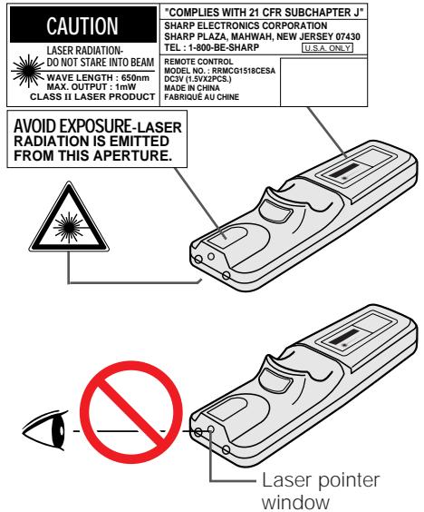
Cautions Concerning the Laser Pointer
The laser pointer on the remote control emits a laser beam from the laser pointer window. This is a Class II laser which may impair your sight if directed into the eyes. The three marks shown on the left are caution labels for the laser beam.
- Do not look into the laser pointer window or shine the laser beam on yourself or others. (The laser beam used in this product is harmless when directed onto the skin. However, be careful not to project the beam directly into the eyes.)
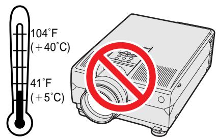
- Always use the laser pointer at temperatures between 41^ and 104^ (+5^ and +40^) .
- Use of controls or adjustments, or performance of procedures other than those specified herein may result in hazardous radiation exposure.
Cautions Concerning the Setup of the Projector
For minimal servicing and to maintain high image quality, SHARP recommends that this projector be installed in an area free from humidity, dust and cigarette smoke. When the projector is subjected to these environments, the lens and filter must be cleaned more often. Periodically the filter should be replaced and the projector should be cleaned internally. As long as the projector is properly maintained in this manner, use in these environments will not reduce the overall operation life. Please note that all internal cleaning must be performed by an Authorized Sharp Industrial LCD Products Dealer or Service Center.
Notes on Operation
- The exhaust vent, the lamp cage cover and adjacent areas may be extremely hot during projector operation. To prevent injury, do not touch these areas until they have sufficiently cooled.
- Allow at least 4 inches (10 cm) of space between the cooling fan (exhaust vent) and the nearest wall or obstruction.
- If the cooling fan becomes obstructed, a protection device will automatically turn off the projector lamp. This does not indicate a malfunction. Remove the projector power cord from the wall outlet and wait at least 10 minutes. Then turn on the power by plugging the power cord back in. This will return the projector to the normal operating condition.
Temperature Monitor Function
If the projector starts to overheat due to setup problems or a dirty air filter, "TEMP." and "X" will flash in the lower-left corner of the picture. If the temperature continues to rise, the lamp will turn off, the TEMPERATURE WARNING indicator on the projector will flash, and after a 90-second cooling-off period the power will shut off. Refer to "Lamp/Maintenance Indicators" on page 47, for details.
NOTE
- The cooling fan regulates the internal temperature, and its performance is automatically controlled. The sound of the fan may change during projector operation due to changes in the fan speed.
PDF operation manuals in all languages are included in the CD-ROM. To utilize these manuals, you need to install Adobe Acrobat Reader on your PC (Windows or Macintosh). If you have not installed Acrobat Reader yet, you can download it from the Internet (http://www.adobe.com) or install it from the CD-ROM.
To Install Acrobat Reader (English version) from the CD-ROM
For Windows:
① Insert the CD-ROM in the CD-ROM drive.
(2) Double click on the "My Computer" icon.
(3) Double click on the "CD-ROM" drive.
(4) Double click on the "manuals" folder.
⑤ Double click on the "acrobat" folder.
(6) Double click on the "windows" folder.
Double click on the installation program and follow the instructions on the screen.
For Macintosh:
(1) Insert the CD-ROM in the CD-ROM drive.
(2) Double click on the "CD-ROM" icon.
③ Double click on the "manuals" folder.
④ Double click on the "acrobat" folder.
⑤ Double click on the "mac" folder.
(6) Double click on the installation program and follow the instructions on the screen.
For other operating systems:
Please download Acrobat Reader from the Internet (http://www.adobe.com).
For other languages:
If you prefer using Acrobat Reader for other languages, please download the appropriate version from the Internet. (Please note that you do not have to have Acrobat Reader in your own language. You can read any pdf file using the English version of Acrobat Reader.)
Accessing the PDF Manuals
For Windows:
① Insert the CD-ROM in the CD-ROM drive.
(2) Double click on the "My Computer" icon.
(3) Double click on the "CD-ROM" drive.
④ Double click on the "manuals" folder.
⑤ Double click on the "xq-nv6xu" folder.
(6) Double click on the language (name of the folder) that you want to view.
Double click on the "nv6" pdf file to access the projector manuals.
Double click on the "saps" pdf file to access the Sharp Advanced Presentation Software manual.
(8) Double click on the pdf file.
For Macintosh:
① Insert the CD-ROM in the CD-ROM drive.
② Double click on the "CD-ROM" icon.
③ Double click on the "manuals" folder.
④ Double click on the "xg-nv6xu" folder.
(5) Double click on the language (name of the folder) that you want to view.
Double click on the "nv6" pdf file to access the projector manuals.
Double click on the "saps" pdf file to access the Sharp Advanced Presentation Software manual.
Double click on the pdf file.
NOTE
- If the desired pdf file cannot be opened by double clicking the mouse, please start Acrobat Reader first, then specify the desired file using the "File", "Open" menu.

For SHARP Assistance (U.S.A. only)
If you encounter any problems during setup or operation of this projector, first refer to the "Troubleshooting" section on page 49. If this operation manual does not answer your question, please call toll free 1-800-BE-SHARP (1-800-237-4277) for further assistance. Or, send us an e-mail at lcdsupport@sharplcd.com.
Our World Wide Web address is http://www.sharp-usa.com/

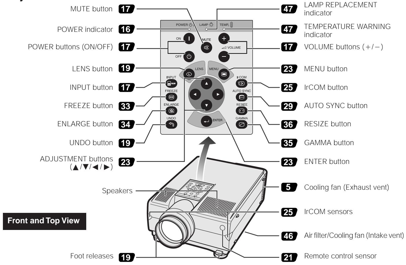
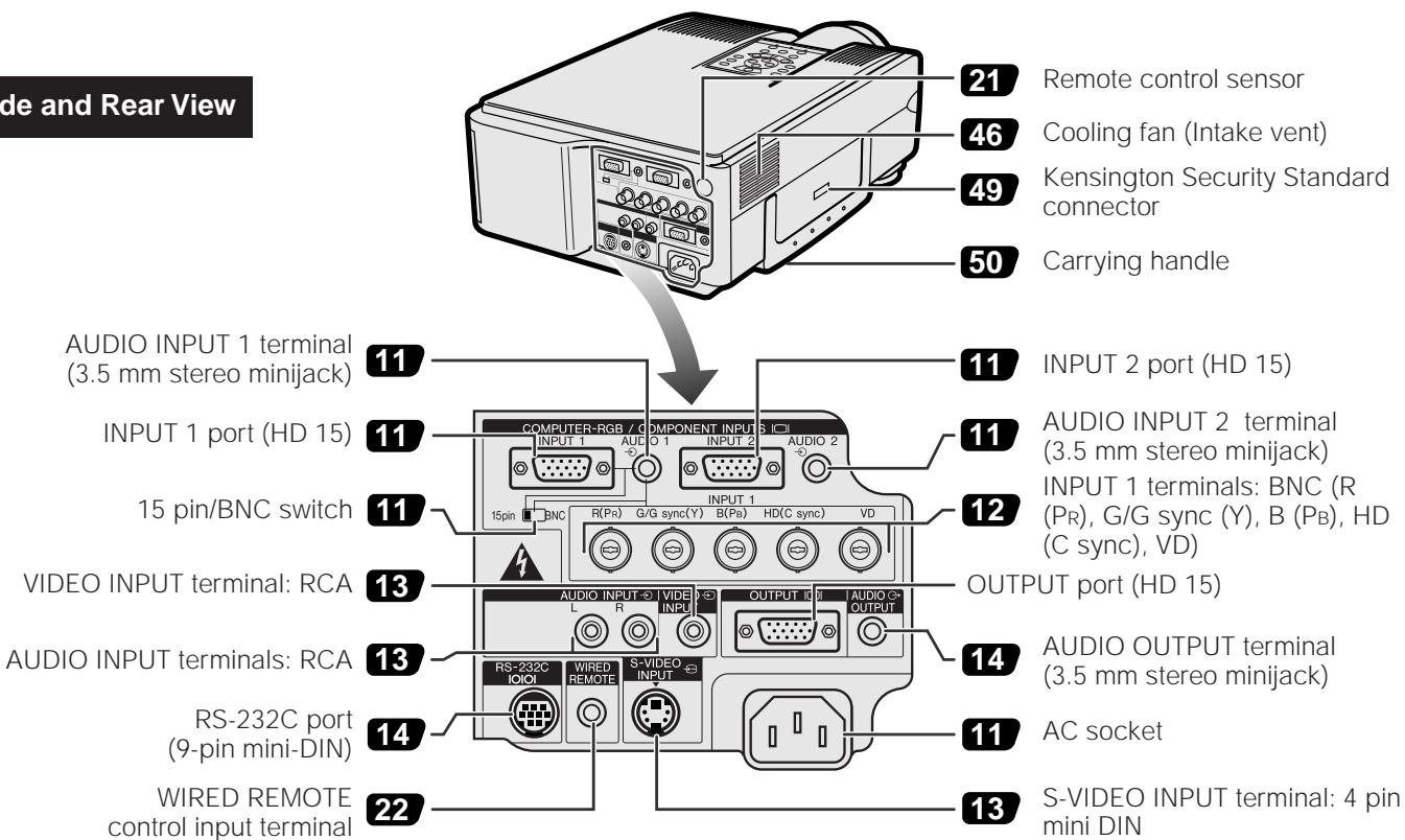
Numbers next to the part names refer to the main pages in this manual where the topic is explained.
Projector
Side and Rear View
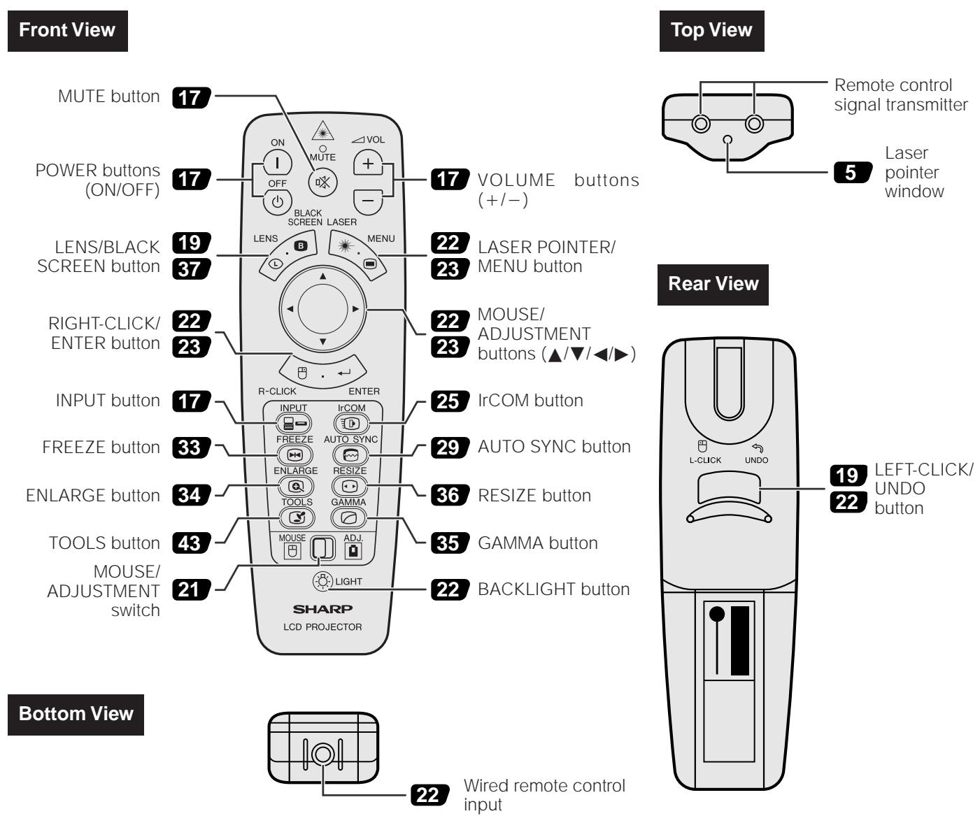
Remote Control
Inserting the batteries
| 1 Press in and downward on the arrow to remove the battery cover. | 2 Insert two AA size batteries for the remote control, making sure their polarities match the + and - marks inside the battery compartment. | 3 Insert the side tabs of the battery cover into their slots and press the cover in until it is properly seated. |
| Battery cover | Battery compartment | Battery cover |

Setup & Connections
Setting up the Projector
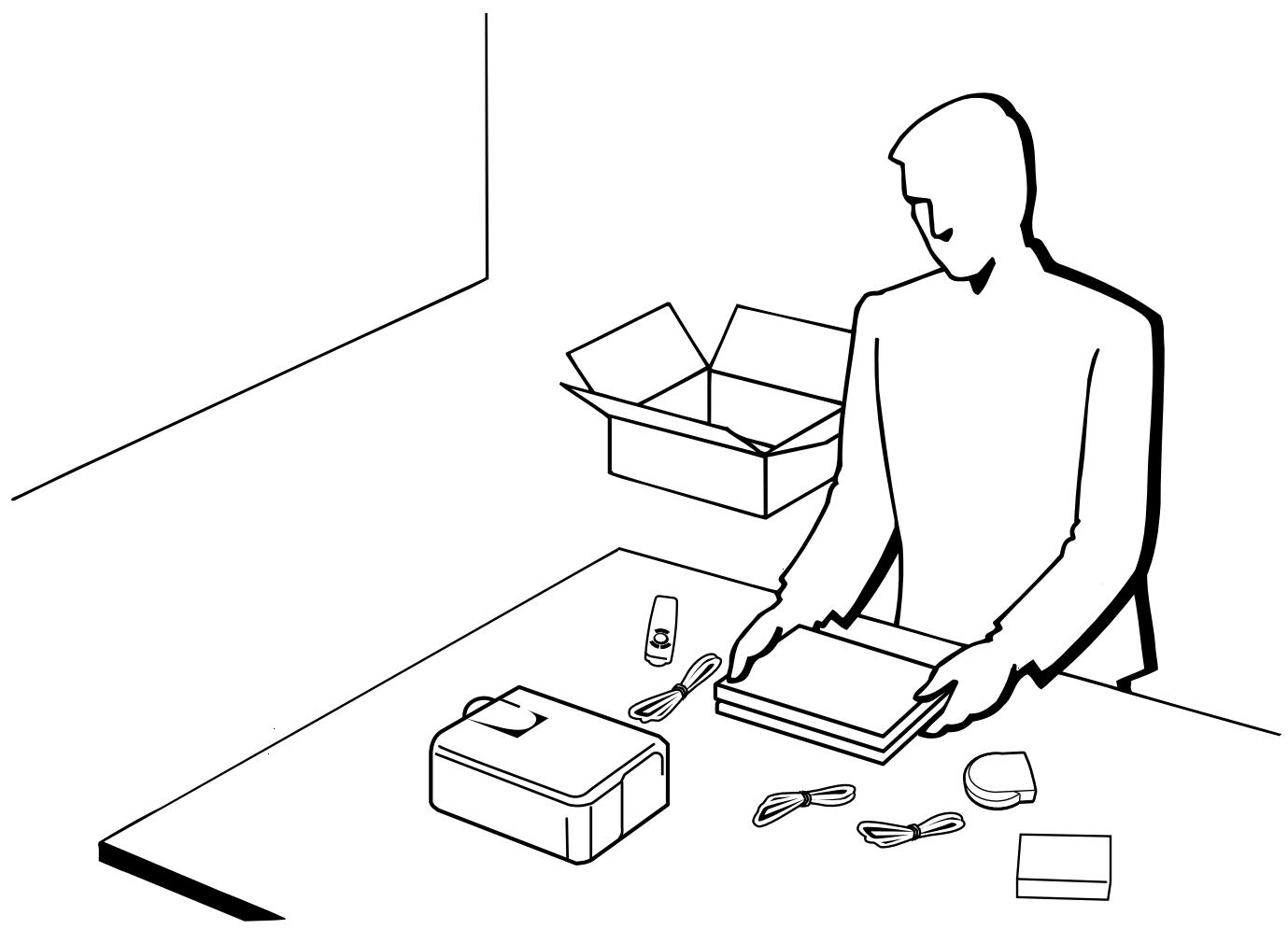
1. Supplied Accessories
Remote control RRMCG1518CESA
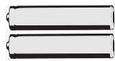
Two AA size batteries
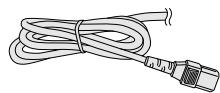
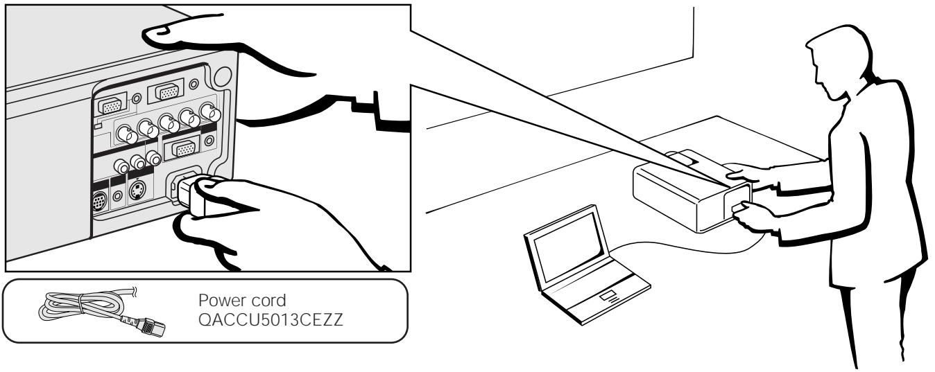
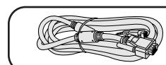
Power cord
QACCU5013CEZZ

Computer cable QCNW-5304CEZZ
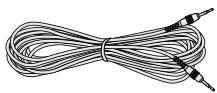
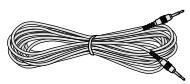
Computer audio cable QCNW-4870CEZZ

Three BNC-RCA adaptors QPLGJ0107GEZZ
Mouse control serial cable QCNW-5112CEZZ
Mouse control cable for IBM PS/2 QCNW-5113CEZZ
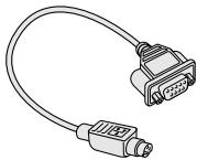
Mouse control cable for Mac QCNW-5114CEZZ

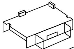
Remote mouse receiver RUNTK0661CEZZ
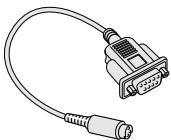
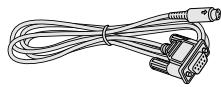
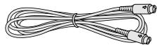
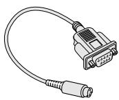
DIN-D-sub RS-232C cable QCNW-5288CEZZ
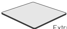
Extra air filter PFILD0080CEZZ

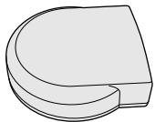
Lens cap PCAPH1056CESA
CD-ROM UDSKA0004CE01
LCD projector operation manual TINS-6737CEZZ
LCD projector quick reference TINS-6738CEZZ
Sharp Advanced Presentation Software operation manual TINS-6739CEZZ
Sharp Advanced Presentation Software quick reference TINS-6740CEZZ
IrDA driver installation instruction sheet TCAUZ3046CEZZ

2. Connecting the Projector
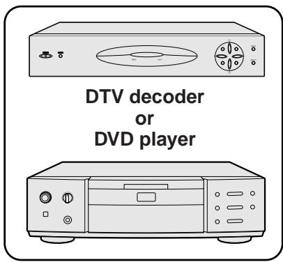
Connecting the Power Cord
Plug the supplied power cord into the AC socket on the back of the projector.
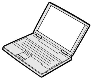
Connecting the Projector to a Computer
You can connect your projector to a computer for projection of full color computer images.

Computer cable QCNW-5304CEZZ
Computer audio cable QCNW-4870CEZZ
CAUTION
- Before connecting, be sure to turn both the projector and the computer off. After making all connections, turn the projector on first. The computer should always be turned on last.
NOTE
- Please read the computer's operation manual carefully.
- Refer to pages 55 and 56 "Input Signals (Recommended Timing)" for a list of computer signals compatible with the projector. Use with computer signals other than those listed may cause some of the functions not to work.
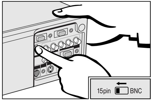
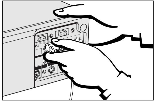
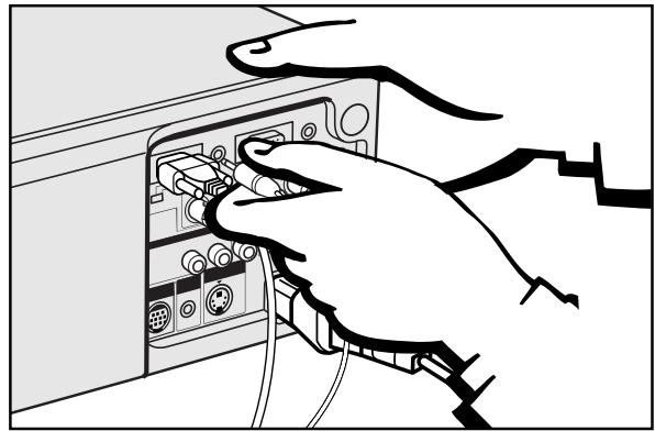
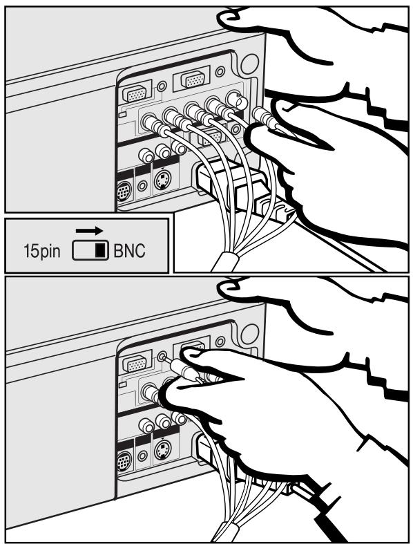
Connecting an IBM-PC or a Macintosh computer
(Slide the 15 pin/BNC switch on the rear terminals to the 15 pin position.)
Plug one end of the supplied computer cable into the INPUT 1 or 2 port on the projector and the other end into the Monitor output port on the computer, and secure the plugs by tightening the thumb screws.
When connecting this projector to a computer, select "Computer/RGB" for "Signal Type" on the GUI menu. (See page 40.)
NOTE
-
A Macintosh adaptor may be required for use with some Macintosh computers. Contact your nearest Authorized Sharp Industrial LCD Products Dealer or Service Center.
-
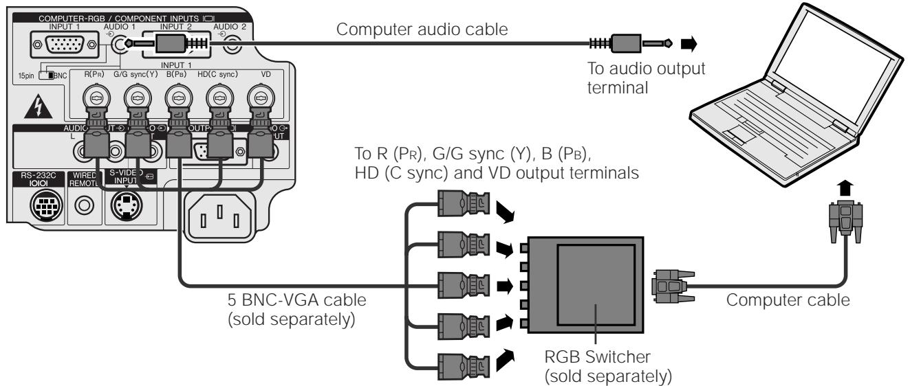
This projector uses a 5 BNC computer input to prevent a deterioration of image quality.
- Connect the R (PR) , G/G sync (Y), B (PB) , HD (C sync) and VD cables to the correct input terminals on the projector and an RGB switcher (sold separately) connected to the computer, or connect a 5 BNC-VGA cable (sold separately) directly from the input terminals on the projector to the computer.
Connecting other compatible computers
Computer cable QCNW-5304CEZZ
Computer audio cable QCNW-4870CEZZ
(Slide the 15 pin/BNC switch on the rear terminals to the BNC position.)
When connecting the projector to a compatible computer other than an IBM-PC (VGA/SVGA/XGA/SXGA/UXGA) or Macintosh (i.e. Workstation), a separate cable may be needed. Please contact your dealer for more information.
When connecting this projector to a computer, select "Computer/RGB" for "Signal Type" on the GUI menu. (See page 40.)
NOTE
- Connecting computers other than the recommended types may result in damage to the projector, the computer, or both.
- AUDIO INPUT 1 or 2 accepts INPUT 1 or 2 port input.
To RGB Switcher
"Plug and Play" function (when connecting to a 15 pin terminal)
- This projector is compatible with VESA-standard DDC 1/DDC 2B. The projector and a VESA DDC compatible computer will communicate their setting requirements, allowing for quick and easy setup.
- Before using the "Plug and Play" function, be sure to turn on the projector first and the connected computer last.
NOTE
- The DDC, Plug and Play function of this projector operates only when used in conjunction with a VESA DDC compatible computer.

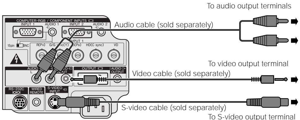
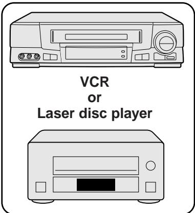
Connecting the Projector to Video Equipment
You can connect your projector to a VCR, laser disc player, DVD player, DTV decoder and other audiovisual equipment.

CAUTION
- Always turn off the projector while connecting to video equipment, in order to protect both the projector and the equipment being connected.
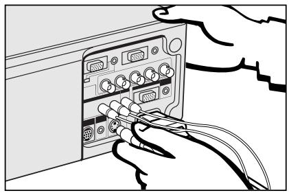
Connecting a VCR, laser disc player and other audiovisual equipment
The S-VIDEO INPUT terminal uses a video signal system in which the picture is separated into a color and a luminance signal to realize a higher-quality image.
NOTE
- If your video equipment does not have an S-video output terminal, use the conventional video output terminal.
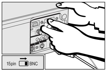
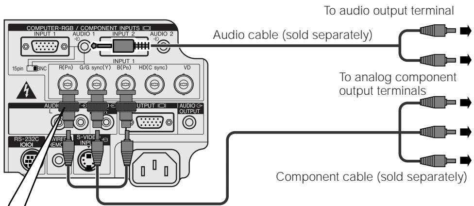
Connecting a DVD player, DTV decoder and other component video equipment
(Slide the 15 pin/BNC switch on the rear terminals to the BNC position.)
When connecting this projector to a DVD player or a DTV decoder, select "Component" for "Signal Type" on the GUI menu. (See page 40.)
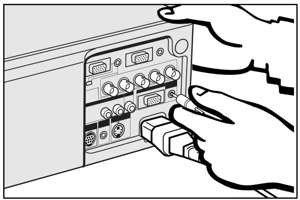
Connecting an amplifier and other audio components
CAUTION
- Always turn off the projector while connecting to audio components, in order to protect both the projector and the components being connected.
NOTE
- By using external audio components, the volume can be amplified for better sound.
Connecting RS-232C Port
When the RS-232C port on the projector is connected to a computer with an RS-232C cable (cross type, sold separately), the computer can be used to control the projector and check the status of the projector. See pages 52 and 53 for details.
Computer cable QCNW-5304CEZZ
Computer audio cable QCNW-4870CEZZ
DIN-D-sub RS-232C cable QCNW-5288CEZZ
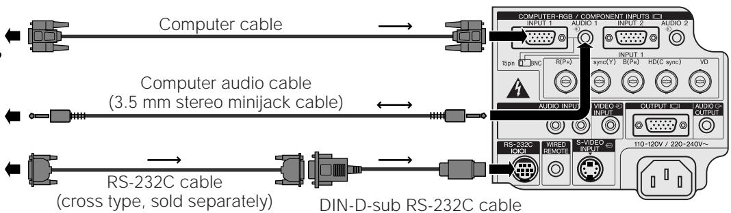
CAUTION
- Do not connect or remove RS-232C cable to or from the computer while it is on. This may damage your computer.
NOTE
- The wireless mouse or RS-232C function may not operate if your computer port is not correctly set up. Please refer to the operation manual of the computer for details on setting up/installing the correct mouse driver.
- The arrows (, ) indicate the direction of the signals.
- A Macintosh adaptor may be required for use with some Macintosh computers. Contact your nearest Authorized Sharp Industrial LCD Products Dealer or Service Center.

Connecting the Remote Mouse Receiver
- You can use the remote control as a remote mouse.
- When the RS-232C port on the projector is connected to a computer with an RS-232C cable (cross type, sold separately), the computer can be used to control the projector and check the status of the projector. See pages 52 and 53 for details.
IBM or IBM compatible PC
① Connect one end of the supplied mouse control cable to the corresponding terminal on the PC.
② Connect the other end to the remote mouse receiver.
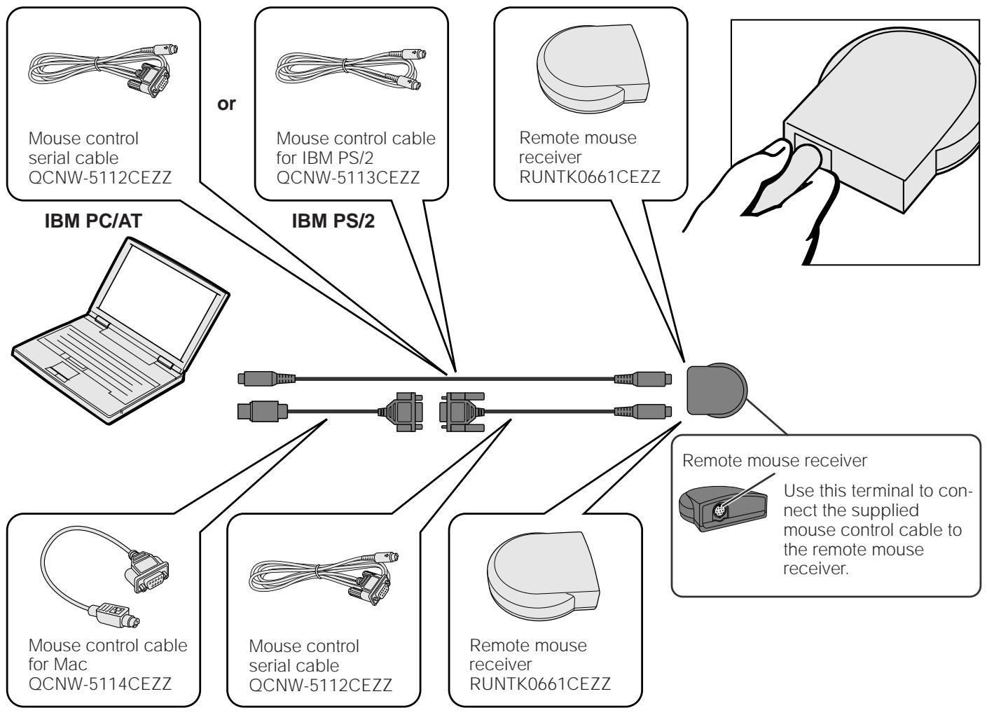
Macintosh
① Connect the mouse control serial cable to the remote mouse receiver.
② Connect the mouse control cable for Mac to the Mac ADB port on the Mac.
③ Connect the other end of the mouse control cable for Mac to the mouse control serial cable.
CAUTION
- Do not connect or remove the mouse control cables to or from the computer while it is on. This may damage your computer.
NOTE
- The wireless mouse functions can operate computers compatible with IBM PS/2, serial (RS-232C) or Apple ADB type mouse systems.


Operation
Basic Operations
1. Turning on/off the Power

Make the necessary connections before proceeding. Connect the power cord to a wall outlet.
The POWER indicator lights up red and the projector enters standby mode.
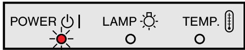
NOTE
- If the bottom filter cover is not securely installed, the POWER indicator flashes.


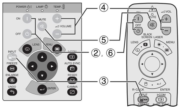
Press Power ON.
NOTE
- The flashing green LAMP REPLACEMENT indicator shows that the lamp is warming up. Wait until the indicator stops flashing before operating the projector.
- If the power is turned off and then immediately turned on again, it may take a short while before the lamp turns on.
- After the projector is unpacked and turned on for the first time, a slight odor may be emitted from the exhaust vent. This odor will soon disappear with use.
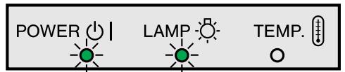
When the power is on, the LAMP REPLACEMENT indicator lights indicating the status of the lamp.
Green: Lamp is ready.
Flashing green: Warming up.
Red: Change the lamp.


Press INPUT to select the desired input mode.
Press INPUT again to change the mode.

INPUT1 Mode
INPUT 2 Mode
VIDEO Mode

NOTE
- When no signal is being received, "NO SIGNAL" will be displayed. When a signal that the projector is not preset to receive is being received, "NOT REG." will be displayed.


Press VOLUME +1- to adjust the volume.


Press MUTE to temporarily turn off the sound. Press MUTE again to turn the sound back on.


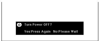
Press POWER OFF. Press POWER OFF again while the message is displayed.
NOTE
- If you accidentally pressed POWER OFF and do not want to turn off the power, wait until the power off screen disappears.
- When POWER OFF is pressed twice, the POWER indicator will light up red and the cooling fan will run for about 90 seconds. The projector will then enter standby mode.
- Wait until the cooling fan stops before disconnecting the power cord.
- The power can be turned on again by pressing POWER ON. When the power is turned on, the POWER indicator and the LAMP REPLACEMENT indicator light green.
- The POWER indicator flashes if the bottom filter cover is not securely installed.
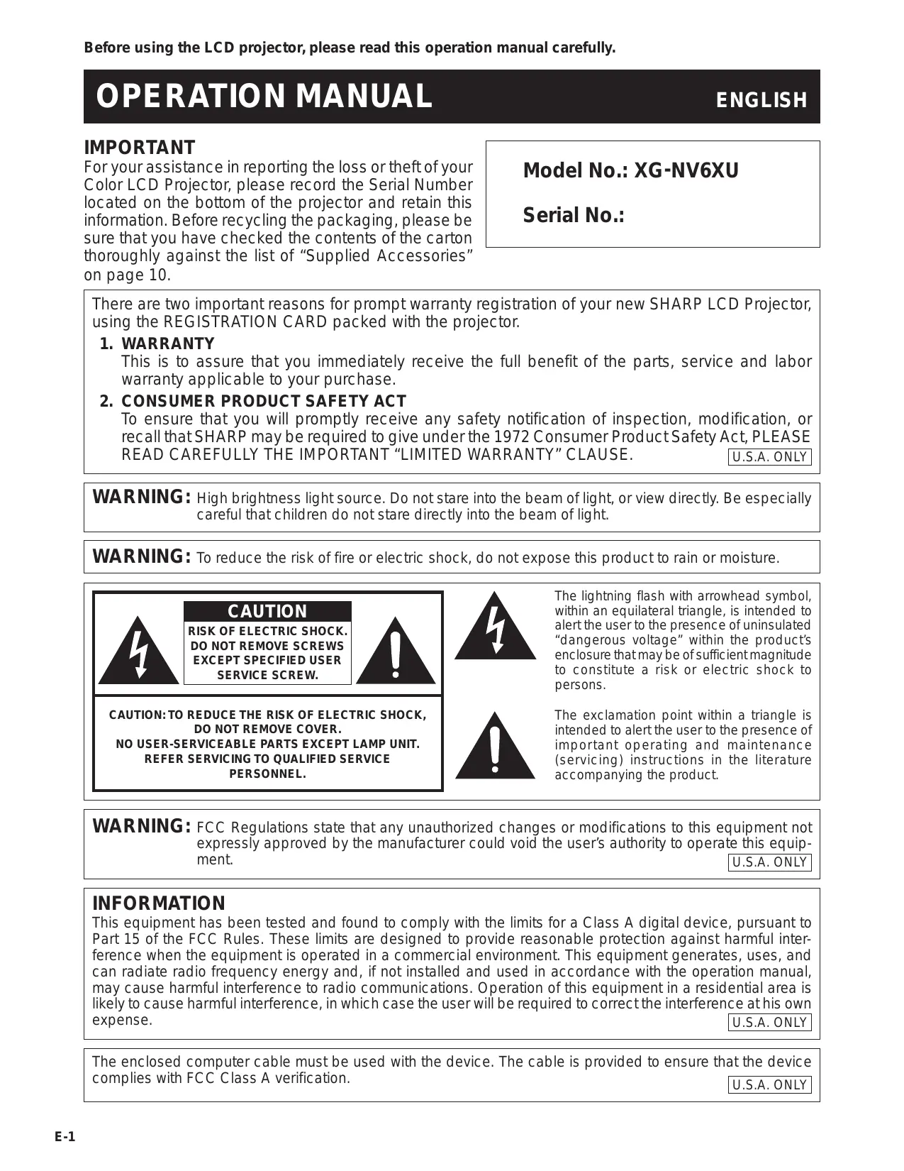
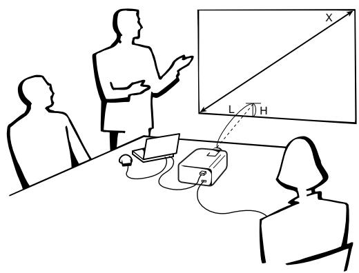
2. Setting up the Screen
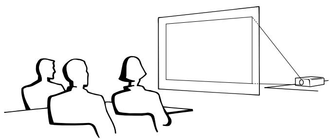
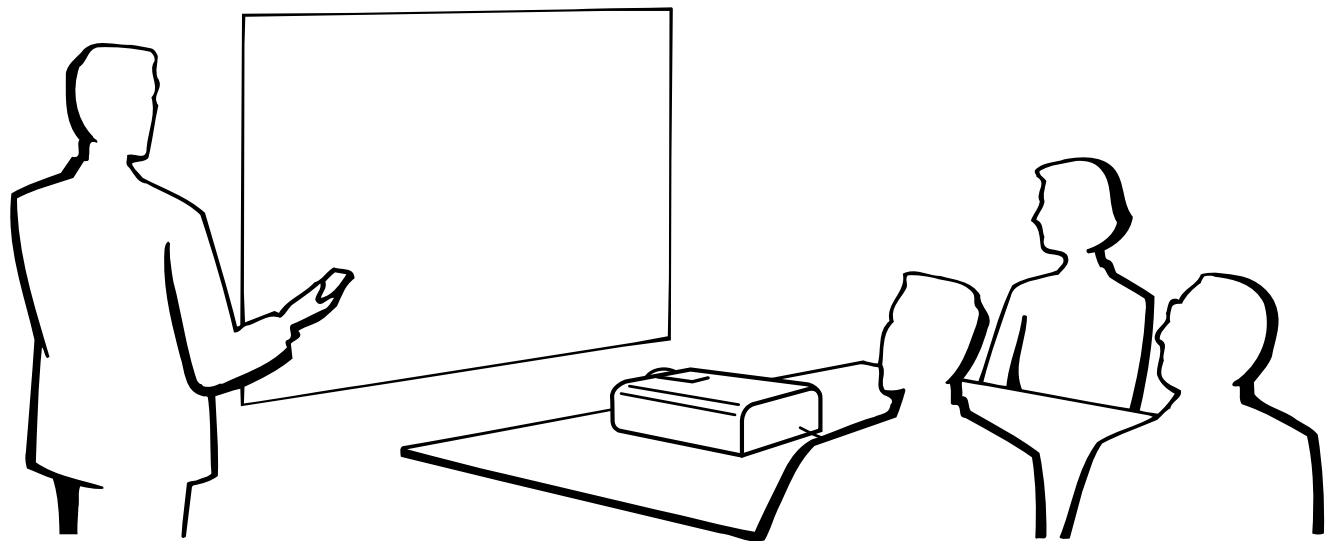
Position the projector perpendicular to the screen with all feet flat and level to achieve an optimal image. Move the projector forward or backward if the edges of the image are distorted.
NOTE
- The projector lens should be centered in the middle of the screen. If the lens center is not perpendicular to the screen, the image will be distorted, making viewing difficult.
- Position the screen so that it is not in direct sunlight or room light. Light falling directly onto the screen washes out colors, making viewing difficult. Close the curtains and dim the lights when setting up the screen in a sunny or bright room.
- A polarizing screen cannot be used with this projector.
Standard Setup (Front Projection)
Place the projector at the required distance from the screen according to the desired picture size (see the table below).
NOTE
- Optional wide and telephoto lenses from Sharp are available for specialized application. Please see your local Sharp Industrial LCD Products Dealer for details on the AN-T6EZ and AN-W6EZ lenses.
NORMAL Mode (4:3)
| Picture size | Projection distance | Distance from the lens center to the bottom of the image (H) | |||
| Diag. | Width | Height | Maximum | Minimum | |
| 300" | 240" | 180" | 47' (14.3 m) | 36' 2" (11.0 m) | 9" (22.9 cm) |
| 200" | 160" | 120" | 32' 2" (9.8 m) | 24' 3" (7.4 m) | 6" (15.2 cm) |
| 150" | 120" | 90" | 23' 6" (7.2 m) | 18' 4" (5.6 m) | 4 1/2" (11.4 cm) |
| 100" | 80" | 60" | 15' 11" (4.9 m) | 12' (3.7 m) | 3" (7.6 cm) |
| 84" | 67" | 50" | 13' 2" (4.0 m) | 10' 1" (3.1 m) | 2 33/64" (6.4 cm) |
| 72" | 58" | 43" | 11' 1" (3.4 m) | 8' 6" (2.6 m) | 2 5/32" (5.5 cm) |
| 60" | 48" | 36" | 9' 6" (2.9 m) | 7' 3" (2.2 m) | 1 51/64" (4.6 cm) |
| 40" | 32" | 24" | 6' 1" (1.9 m) | 4' 7" (1.4 m) | 1 13/64" (3.1 cm) |
The formula for picture size and projection distance
y_1 = (0.0482x - 0.0226)× 3.28
y_2 = (0.037x - 0.041)× 3.28
y_3 = 0.03x
x : Picture size (diag.) (inches)
y_t : Maximum projection distance (feet)
y_2 : Minimum projection distance (feet)
y_3 : Distance from the lens center to the bottom of the image (H) (inches)
WIDE Mode (16:9)
| Picture size | Projection distance | Distance from the lens center to the bottom of the image (H) | |||
| Diag. | Width | Height | Maximum | Minimum | |
| 300" | 261" | 147" | 51' 3" (15.6 m) | 39' 5" (12.0 m) | -14 45/64" (-37.4 cm) |
| 200" | 174" | 98" | 34' 5" (10.5 m) | 26' 5" (8.1 m) | -9 13/16" (-24.9 cm) |
| 150" | 131" | 74" | 25' 11" (7.9 m) | 19' 11" (6.1 m) | -7 11/32" (-18.7 cm) |
| 133" | 116" | 65" | 23' (7.0 m) | 17' 7" (5.4 m) | -6 33/64" (-16.6 cm) |
| 106" | 92" | 52" | 18' 3" (5.6 m) | 14' (4.3 m) | -5 13/64" (-13.2 cm) |
| 100" | 87" | 49" | 17' (5.2 m) | 13' 1" (4.0 m) | -4 29/32" (-12.5 cm) |
| 92" | 80" | 45" | 15' 10" (4.8 m) | 12' 1" (3.7 m) | -4 33/64" (-11.5 cm) |
| 84" | 73" | 41" | 14' 1" (4.3 m) | 10' 10" (3.3 m) | -4 1/8" (-10.5 cm) |
| 72" | 63" | 35" | 12' (3.7 m) | 9' 3" (2.8 m) | -3 17/32" (-9.0 cm) |
| 60" | 52" | 29" | 10' 2" (3.1 m) | 7' 10" (2.4 m) | -2 15/16" (-7.5 cm) |
| 40" | 35" | 20" | 6' 6" (2.0 m) | 5' (1.5 m) | -1 61/64" (-5.0 cm) |
The formula for picture size and projection distance
y_t = (0.0525x - 0.0546)× 3.28
y_2 = (0.0404x - 0.0397)× 3.28
y_3 = -0.049x
x : Picture size (diag.) (inches)
y_t : Maximum projection distance (feet)
y: Minimum projection distance (feet)
y_3 : Distance from the lens center to the bottom of the image (H) (inches)
NOTE
- There is an error of ± 3% in the formula above.
- Values with a minus (-) sign indicate the distance of the lens center below the bottom of the screen.

Using the Adjustment Feet
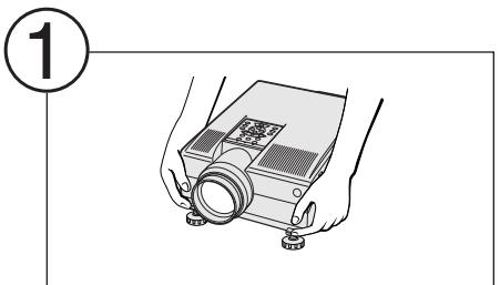
Press foot releases.
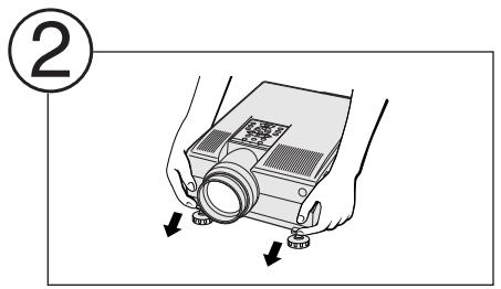
Adjust height of projector and remove hands from foot releases.

Rotate feet to make minor changes.
NOTE
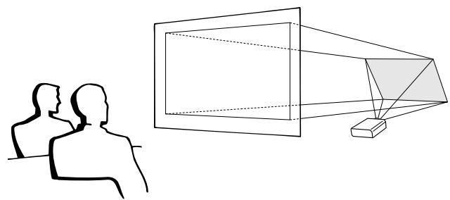
- The projector is adjustable up to approximately 5^ from the standard position.
- When the height of the projector is adjusted, the image may become distorted (keystoned), depending on the relative positions of the projector and the screen.
CAUTION
- Do not press the foot releases when the adjustment feet are extended without firmly holding the projector.
- Do not hold the lens when lifting or lowering the projector.
- When lowering the projector, be careful not to get your fingers caught in the area between the adjustment feet and the projector.
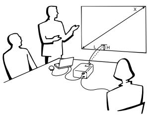
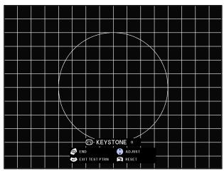
Digital Lens Adjustment
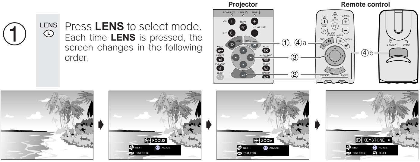


Press ENTER to display test pattern.
Press / / to make adjustments.
a. Press LENS until normal screen appears.
b. To reset the KEYSTONE setting, press UNDO.
NOTE
- Straight lines and the edges of the displayed image may appear jagged, when adjusting the KEYSTONE setting.
- Do not touch the lens when adjusting the focus or zoom.
Reversed Image Setup
Rear projection
- Place a translucent screen between the projector and the audience.
- Use the projector's menu system to reverse the projected image. (See page 42 for use of this function.)
Projection using a mirror
- Place a mirror (normal flat type) in front of the lens.
- Use the projector's menu system to reverse the projected image. (See page 42 for use of this function.)
- The image reflected from the mirror is projected onto the screen.
NOTE
- Optimal image quality is produced with the projector positioned perpendicular to the screen with all feet flat and level.
CAUTION
- When using a mirror, be sure to carefully position both the projector and the mirror so the light does not shine into the eyes of the audience.
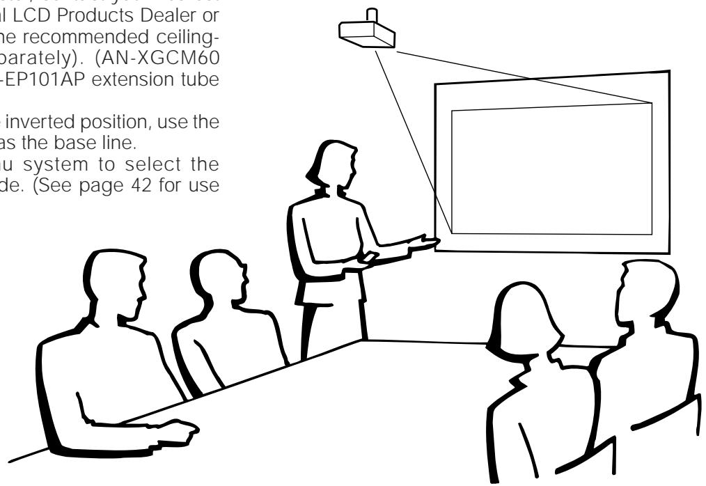
Ceiling-mount Setup
- It is recommended that you use the optional Sharp ceiling-mount bracket for this installation.
- Before mounting the projector, contact your nearest Authorized Sharp Industrial LCD Products Dealer or Service Center to obtain the recommended ceiling-mount bracket (sold separately). (AN-XGCM60 ceiling-mount bracket, AN-EP101AP extension tube for AN-XGCM60.)
- When the projector is in the inverted position, use the upper edge of the screen as the base line.
- Use the projector's menu system to select the appropriate projection mode. (See page 42 for use of this function.)
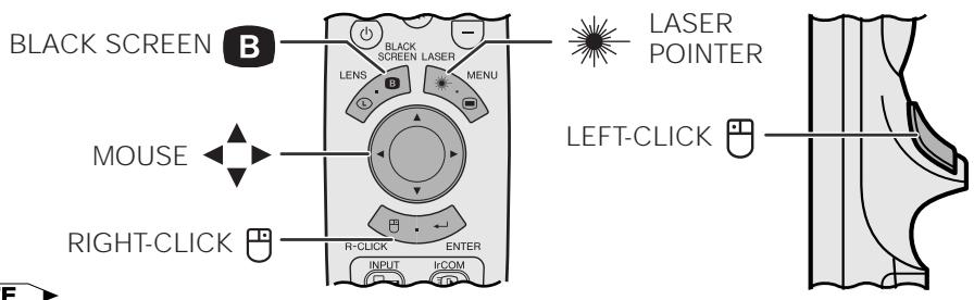
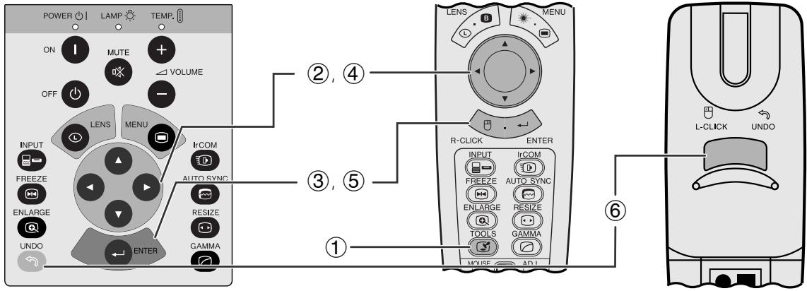
Using the Remote Control as a Wireless Mouse
The remote control has the following three functions:
- Projector control
- Wireless mouse
- Laser pointer
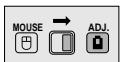
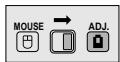
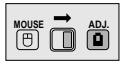
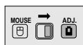
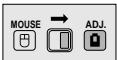
MOUSE/ADJUSTMENT switch (Remote control)
Wireless mouse Laser pointer
Projector control
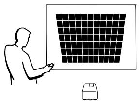
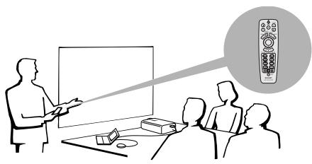
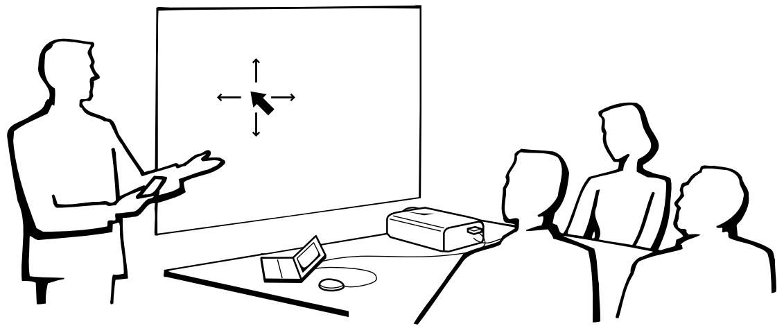
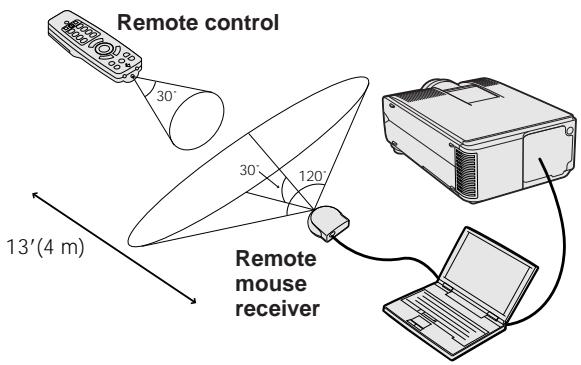
Remote Control/Mouse Receiver Positioning
- The remote control can be used to control the projector within the ranges shown below.
- The remote mouse receiver can be used with the remote control to control the mouse functions of a connected computer within the ranges shown below.
NOTE
- The signal from the remote control can be reflected off a screen for easy operation. However, the effective distance of the signal may differ due to the screen material.
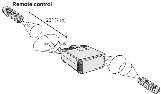
Controlling the Projector
Remote control
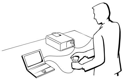
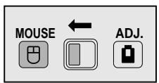
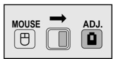
Using the Wireless Mouse
Use as a Wireless Mouse

Be sure the supplied remote mouse receiver is connected to your computer.
Slide the MOUSE/ADJUSTMENT switch to MOUSE.
Effective buttons in MOUSE mode
NOTE
- The wireless mouse may not operate correctly if your computer serial port is not correctly set up. Refer to the computer's operation manual for details of setting up/installing the mouse driver.
- For one-button mouse systems, use either the LEFT-CLICK or RIGHT-CLICK button.
LIGHT

Using the remote control in a dark room
Press BACKLIGHT, and the buttons will light up. Green lights refer to mouse operations, and red lights to projector adjustments.
| Button name | Position of MOUSE/ADJUSTMENT switch | |
| MOUSE←→ ADJ. | ||
| LASER POINTER/MENU | LASER POINTER (GREEN) | MENU (RED) |
| BLACK SCREEN/LENS | BLACK SCREEN (GREEN) | LENS (RED) |
| RIGHT-CLICK/ENTER | RIGHT-CLICK (GREEN) | ENTER (RED) |
| MOUSE/ADJUSTMENT | MOUSE (NOT LIT) | ADJUSTMENT (NOT LIT) |
| LEFT-CLICK/UNDO | LEFT-CLICK (NOT LIT) | UNDO (NOT LIT) |
| POWER ON/OFF | ON (RED) | |
| VOLUME + / - | ||
| MUTE | ||
| Button name | Position of MOUSE/ADJUSTMENT switch |
| MOUSE ☑ ←→ ADJ. ☑ | |
| INPUT | ON (RED) |
| IrCOM | |
| FREEZE | |
| AUTO SYNC | |
| ENLARGE | |
| RESIZE | |
| TOOLS | |
| GAMMA |
Use as a Laser pointer

Slide the MOUSE/ADJUSTMENT switch to MOUSE.

Press LASER POINTER ( ) to activate the laser pointer.
When the button is released, the light automatically goes off.
NOTE
- For safety, the laser pointer automatically goes off after 1 minute of continuous use. To turn it on, release LASER POINTER ( ) and press again.
Wired Remote Control
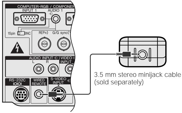
When the remote control cannot be used due to the range or positioning of the projector (rear projection, etc.), connect a 3.5mm stereo minijack cable (sold separately) from the wired remote control input on the bottom of the remote control to the WIRED REMOTE control input terminal on the rear of the projector.
NOTE
- The laser pointer and wireless mouse functions can still be operated with the wired remoto control.

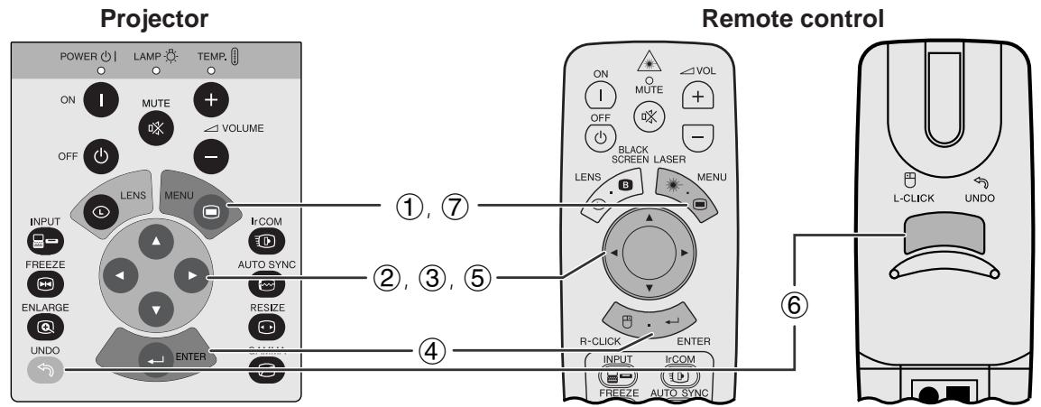
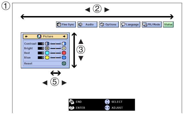
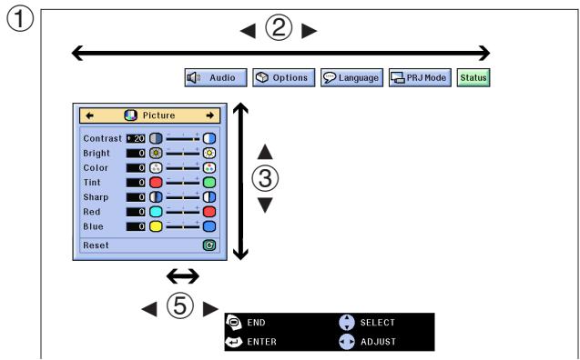
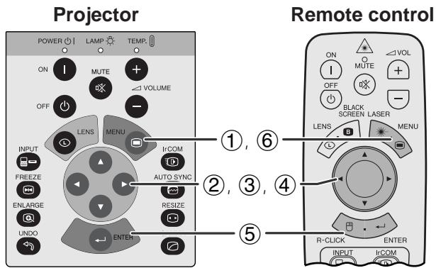
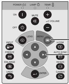
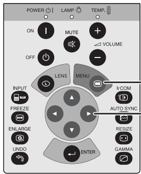
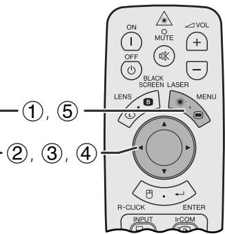
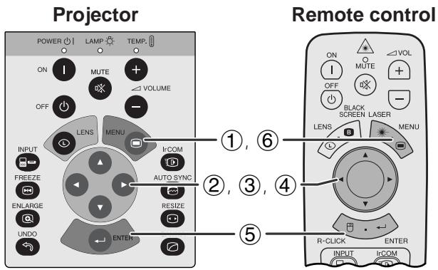
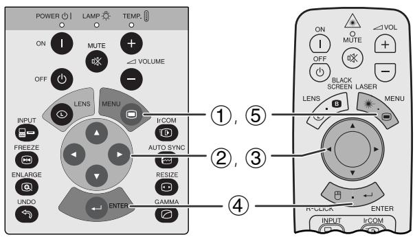
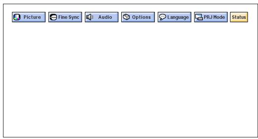
This projector has two sets of menu screens (INPUT/VIDEO) that allow you to adjust the image and various projector settings. These menu screens can be operated from the projector or the remote control with the following buttons.
GUI) On-screen Display
INPUT (COMPUTER/RGB) mode
VIDEO mode
(Slide the MOUSE/ADJUSTMENT switch on the remote control to the ADJ. position.)
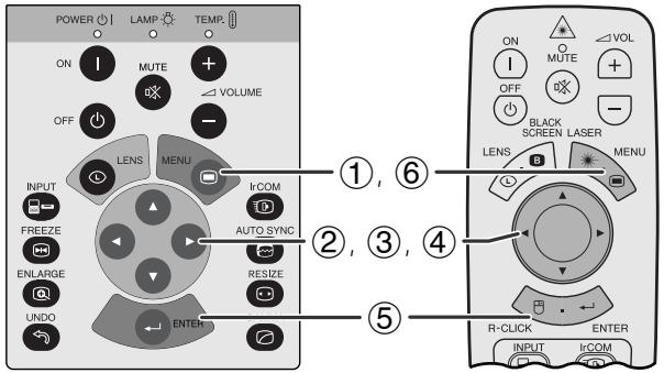
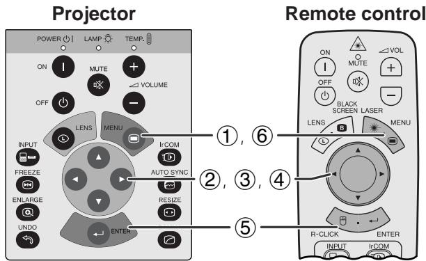
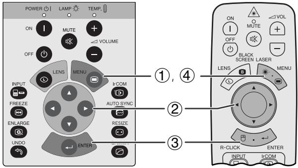
① Press MENU to display the INPUT or VIDEO mode menu bar.
(2) Press / to select an adjustment menu on the menu bar.
(3) Press / to select a specific adjustment item.
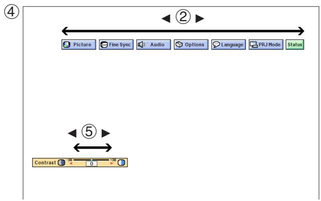
(4) To display a single adjustment item, press ENTER after selecting the item. Only the menu bar and the selected adjustment item will appear.
⑤ Press to adjust the item.
(6) Press UNDO to return to the previous screen.
⑦ Press MENU to exit from the GUI.
NOTE
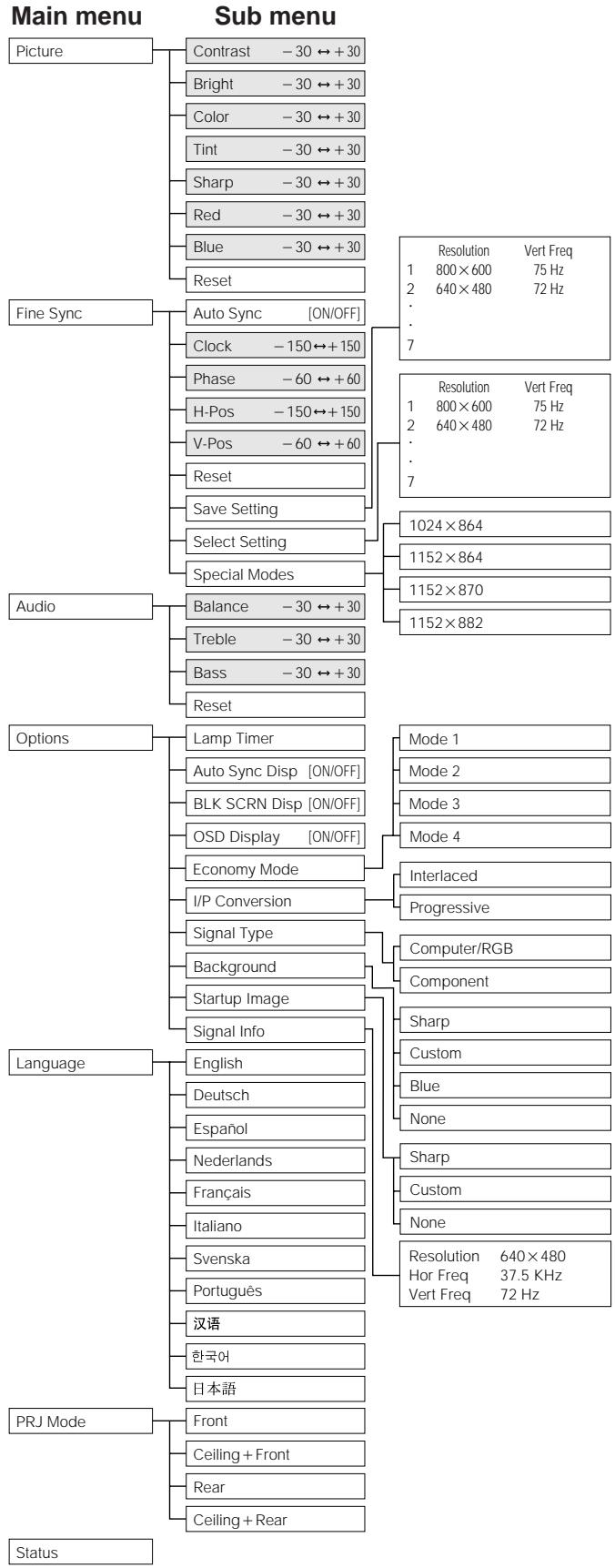
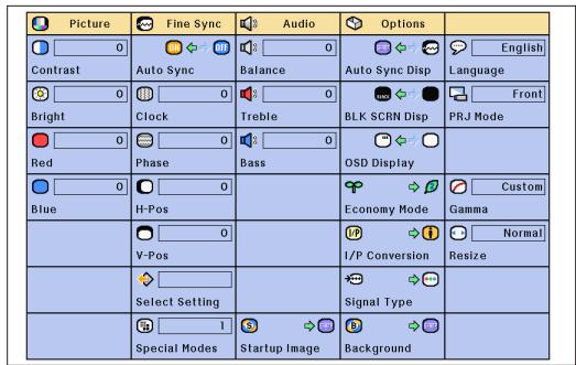
- For details on items on the menu screen, see the tree charts on the next page.
Items on the INPUT1 or INPUT2 Mode Menu Bar
Items on the VIDEO Mode Menu Bar
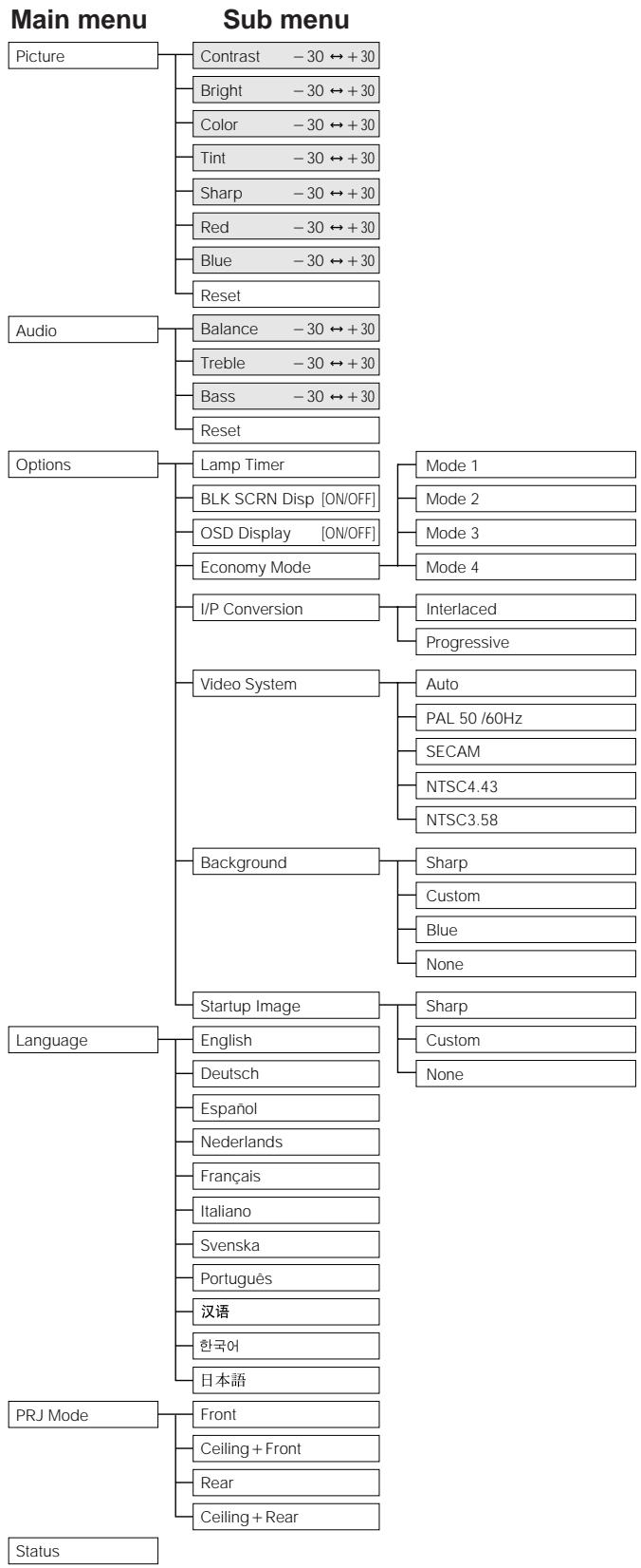
NOTE
- The resolution, vertical frequency and horizontal frequency figures displayed above are for example purposes only.
- "Color", "Tint", and "Sharp" appear only when Component input is selected in INPUT mode.
- Only the items highlighted in the tree charts above can be adjusted.
- To adjust the items under the sub menu, press after selecting the sub menu.

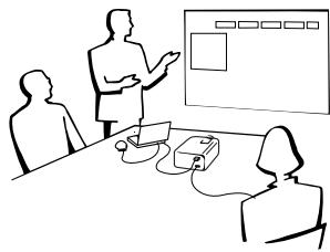
The IrCOM function can transfer still images from a computer or digital camera to the projector via infrared (wireless) communication.
Sharp Advanced Presentation Software
- This function requires the supplied Sharp Advanced Presentation Software (SAPS).
- Install the SAPS in the supplied CD-ROM on the computer.
- See the operation manual of the software for installation and operating instructions.
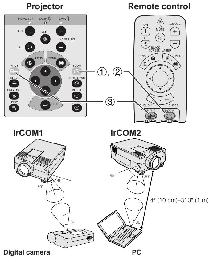
- Position the projector and the IrCOM transmitting device within the range shown on the left.
NOTE
-
To avoid transmission errors or changes in the image, ensure the following when setting up the projector and transmitting device.
-
The IrCOM sensors on both the projector and transmitting device are protected from direct sunlight or strong ambient light.
- The transmitting device has sufficient battery power.
- The projector and transmitting device are positioned within the designated operating range.
-
The IrCOM sensors on the projector and transmitting device are correctly aligned.
-
The distance between the projector and transmitting device may have to be less than 4'' (10 cm) depending on the transmitting device.
- When using the digital still camera, set it to the image transmission mode and set the computer to the image reception mode.
- Align the projector and transmitting device at the same height and angle at a distance of 4^ (10 cm) to 3^ 3^ (1 meter) with an unobstructed line of view.
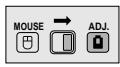
(Slide the MOUSE/ADJUSTMENT switch on the remote control to the ADJ. position.)
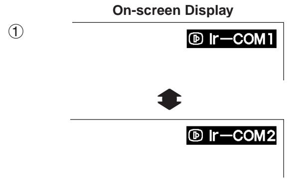
① Press IrCOM to enter the IrCOM mode. Each time IrCOM is pressed, the On-screen Display switches between "Ir-COM1" and "Ir-COM2".
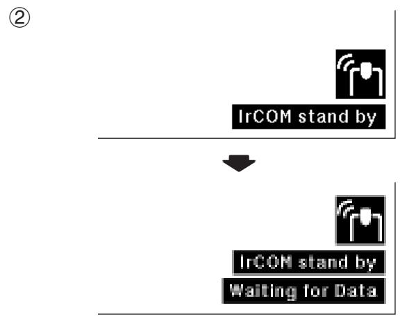
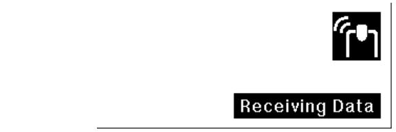
(2) And then the On-screen Display changes as shown on the left.
NOTE
- If the On-screen Display does not change as shown on the left, the projector may not be within the reception range from the IrCOM transmitting device.
③ Press INPUT to exit the IrCOM mode.
NOTE
- If the projector is unable to receive images from the IrCOM transmitting device, the On-screen display on the left will appear.
Projector
Remote control
GUI) On-screen Display
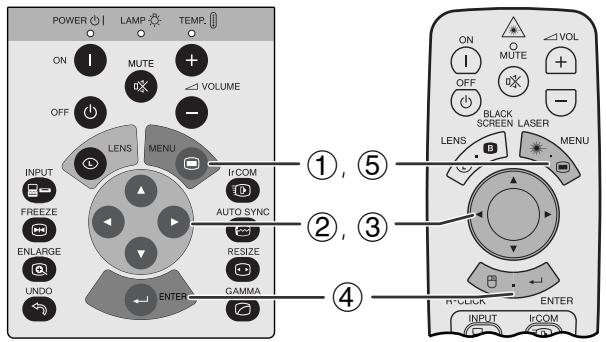
English is the preset language for the On-screen Display. It can be changed to English, German, Spanish, Dutch, French, Italian, Swedish, Portuguese, Chinese, Korean or Japanese.
(Slide the MOUSE/ADJUSTMENT switch on the remote control to the ADJ. position.)
① Press MENU.
② Press to select "Language".
(3) Press / to select the desired language.
④ Press ENTER to save the setting. The On-screen Display is now programmed to display in the language selected.
(5) To exit from the GUI, press MENU.

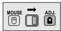
Selecting the Video Input System Mode (VIDEO mode only)
Projector
Remote control
(3)
(4)
C
GUI) On-screen Display
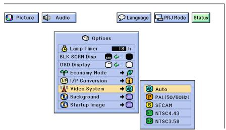
The video input system mode is preset to "Auto"; however, it can be changed to a specific system mode, if the selected system mode is not compatible with the connected audiovisual equipment.
(Slide the MOUSE/ADJUSTMENT switch on the remote control to the ADJ. position.)

① Press MENU.
② Press to select "Options".
③ Press / to select "Video System", and then press .
(4) Press / to select the desired video system mode.
(5) Press ENTER to save the setting.
(6) To exit from the GUI, press MENU.
NOTE
- When the system mode is set to "Auto", you may not receive a clear picture due to signal differences. Should this occur, switch to the video system you are viewing.
GUI) On-screen Display (COMPUTER/RGB input in INPUT mode)
①
(2)
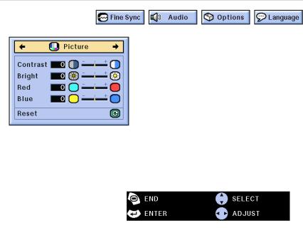
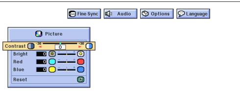
You can adjust the projector's picture to your preferences with the following picture settings.
Description of Adjustment Items
| Selected item | ▲ button | ▶ button |
| Contrast | For less contrast | For more contrast |
| Bright | For less brightness | For more brightness |
| Color | For less color intensity | For more color intensity |
| Tint | Skin tones become purplish | Skin tones become greenish |
| Sharp | For less sharpness | For more sharpness |
| Red | For weaker red | For stronger red |
| Blue | For weaker blue | For stronger blue |
| Reset | All image adjustment items are returned to the factory preset settings. | |
NOTE
- "Color", "Tint" and "Sharp" do not appear for COMPUTER/ RGB input in INPUT mode.
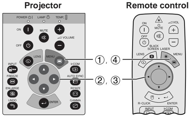
(Slide the MOUSE/ADJUSTMENT switch on the remote control to the ADJ. position.)
① Press MENU. Menu bar and "Picture" menu screen appear. GUI operation guide is also displayed.
② Press / to select a specific adjustment item.
③ Press to move the 1 mark of the selected adjustment item to the desired setting.
(4) To exit from the GUI, press MENU.
NOTE
- To reset all adjustment items, select "Reset" on the "Picture" menu screen and press ENTER.
- The adjustments can be stored separately in the "INPUT 1", "INPUT 2" and "VIDEO" modes.
- For COMPONENT input in INPUT mode, "Sharp" is adjustable only when a DVD player is connected.
(GUI) On-screen Display
(2)
(3)
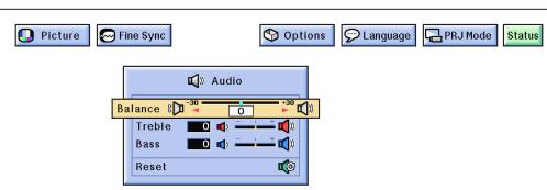
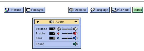
This projector's audio is factory preset to standard settings. However, you can adjust it to suit your own preferences by adjusting the following audio settings.
Description of Adjustment Items
| Selected item | ▲ button | ▲ button |
| Balance | Increased audio from the left speaker | Increased audio from the right speaker |
| Treble | For weaker treble | For stronger treble |
| Bass | For weaker bass | For stronger bass |
| Reset | All audio adjustment items are returned to the factory preset settings. | |
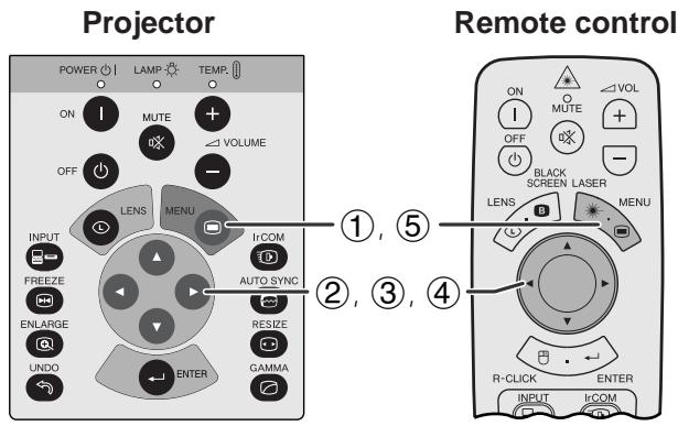
(Slide the MOUSE/ADJUSTMENT switch on the remote control to the ADJ. position.)
① Press MENU. Menu bar and "Picture" menu screen appear. GUI operation guide is also displayed.
② Press to select "Audio".
(3) Press / to select a specific adjustment item.
④ Press to move the mark of the selected adjustment item to the desired setting.
(5) To exit from the GUI, press MENU
NOTE
- To reset all adjustment items, select "Reset" on the "Audio" menu screen and press ENTER.
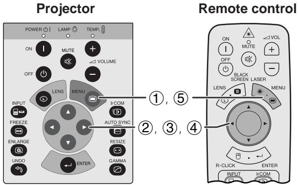
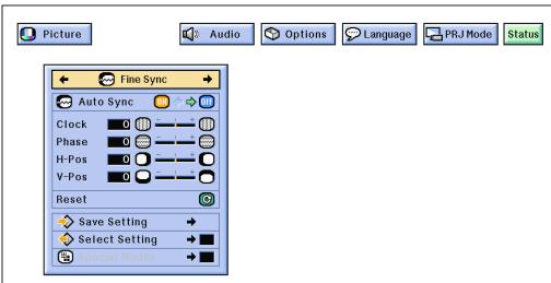
When displaying computer patterns which are very detailed (tiling, vertical stripes, etc.), interference may occur between the LCD pixels, causing flickering, vertical stripes, or contrast irregularities in portions of the screen. Should this occur, adjust "Clock", "Phase", "H-Pos" and "V-Pos" for optimum computer image.
Description of Adjustment Items
| Selected item | Description |
| Clock | Adjusts vertical noise. |
| Phase | Adjusts horizontal noise (similar to tracking on your VCR). |
| H-Pos | Centers the on-screen image by moving it to the left or right. |
| V-Pos | Centers the on-screen image by moving it up or down. |
NOTE
- Computer image adjustment can be made easily by pressing AUTO SYNC (2). See the next page for details.
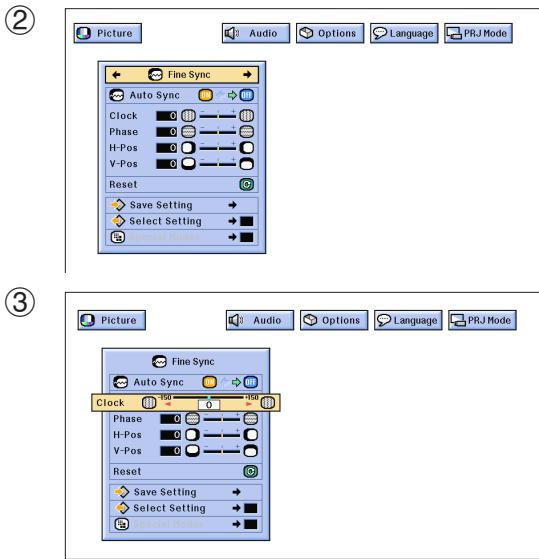
(GUI) On-Screen Display
(Select the desired computer input mode with INPUT.)
(Slide the MOUSE/ADJUSTMENT switch on the remote control to the ADJ. position.)
① Press MENU. Menu bar and “Picture” menu screen appear. GUI operation guide is also displayed.
② Press to select "Fine Sync".
(3) Press to select a specific adjustment item.
④ Press to move the 1 mark of the selected adjustment item to the desired setting.
(5) To exit from the GUI, press MENU.
NOTE
- To reset all adjustment items, select "Reset" on the "Fine Sync" menu screen and press ENTER.
(GUI) On-screen Display
On-screen Display
(GUI) On-screen Display
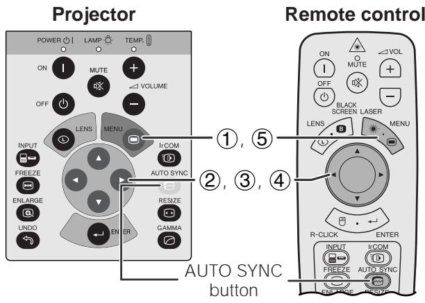
Auto Sync Adjustment
Used to automatically adjust a computer image.
- Auto Sync adjustment can be made manually by pressing AUTO SYNC, or automatically by setting "Auto Sync" to "ON" in the projector's GUI menu.
When "Auto Sync" is set to "ON":
- The sync adjustment is automatically made each time the projector is turned on while connected to a computer or the input selection is changed.
- The Auto Sync adjustment setting previously made is cleared when the projector's setting is changed.
(Slide the MOUSE/ADJUSTMENT switch on the remote control to the ADJ. position.)

① Press MENU.
② Press to select "Fine Sync".
③ Press / to select "Auto Sync".
④ Press to select "ON".
(5) To exit from the GUI, press MENU.
NOTE
Automatic adjustments can be made by pressing AUTO SYNC.
- When the optimum image cannot be achieved with Auto Sync adjustment, use manual adjustments. (See the previous page.)
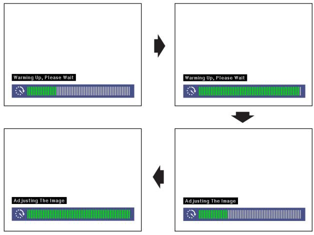
During Auto Sync adjustment, the On-screen Display changes as shown on the left.
NOTE
- Auto Sync adjustment may take some time to complete, depending on the image of the computer connected to the projector.
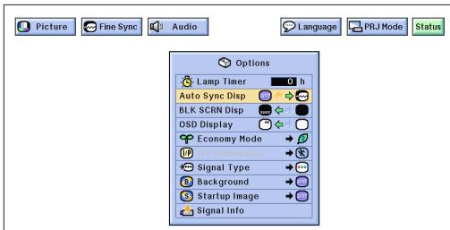
Auto Sync Display Function
Normally, an image is not superimposed during Auto Sync adjustment. You can, however, choose to superimpose a background image during Auto Sync adjustment.
(Slide the MOUSE/ADJUSTMENT switch on the remote control to the ADJ. position.)
① Press MENU.
② Press / to select "Options".
③ Press to select "Auto Sync Disp".
④ Press / to select “□” to superimpose a background image or “ ” to remove the background image during Auto Sync adjustment.
(5) To exit from the GUI, press MENU.

(GUI) On-screen Display
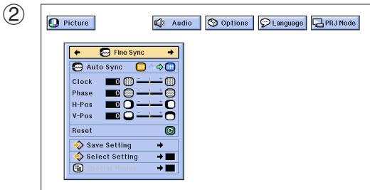
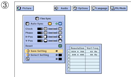
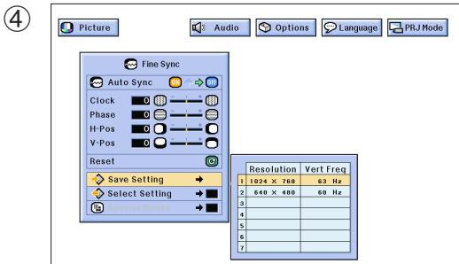
Saving and Selecting Adjustment Settings
This projector allows you to store up to seven adjustment settings for use with various computers. Once these settings are stored, they can be easily selected each time you connect the computer to the projector.
Saving the adjustment setting
(Slide the MOUSE/ADJUSTMENT switch on the remote control to the ADJ. position.)
① Press MENU.
② Press to select "Fine Sync".
(3) Press / to select "Save Setting", and then press .
④ Press / to select the desired memory location of the setting.
(5) Press ENTER to save the setting.
(6) To exit from the GUI, press MENU.
Selecting a saved setting
(Slide the MOUSE/ADJUSTMENT switch on the remote control to the ADJ. position.)
① Press MENU.
② Press to select "Fine Sync".
(3) Press / to select "Select Setting", and then press .
④ Press / to select the desired memory setting.
⑤ Press ENTER to select the setting.
(6) To exit from the GUI, press MENU.
NOTE
- If the memory position has not been set, the resolution and frequency will not be displayed.
- When selecting the stored adjustment setting with "Select Setting", the computer system should match the stored setting.

Projector
GUI) On-screen Display
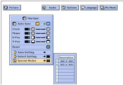
Special Mode Adjustment
Ordinarily, the type of input signal is detected and the correct resolution mode is automatically selected. However, for some signals, "Special Modes" on the "Fine Sync" menu screen may need to be changed to match the computer display mode.
(Slide the MOUSE/ADJUSTMENT switch on the remote control to the ADJ. position.)
① Press MENU.
② Press to select "Fine Sync".
③ Press to select "Special Modes".
④ Press / to select the optimal resolution mode.
(5) Press ENTER to save the setting.
(6) To exit from the GUI, press MENU.
NOTE
- Avoid displaying computer patterns which repeat every other line (horizontal stripes). (Flickering may occur, making the image hard to see.)
- When inputting DTV 480P signals, select "480P" in step ④ above.


Freeze Function
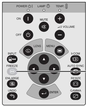
Projector
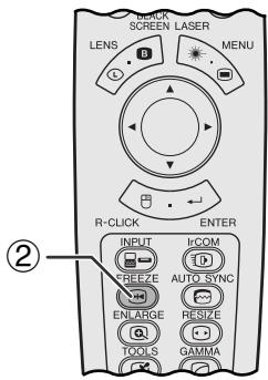
Remote control
1 ①
This function allows you to instantly freeze a moving image. This is useful when you want to display a still image from a computer or video, giving you more time to explain the image to the audience.
You can also use this function to display a still image from a computer while you make preparations for the next computer images to be presented.
(1) Press FREEZE to freeze the image.
(2) Press FREEZE again to return to the moving image.
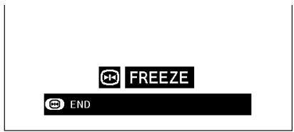
On-screen Display
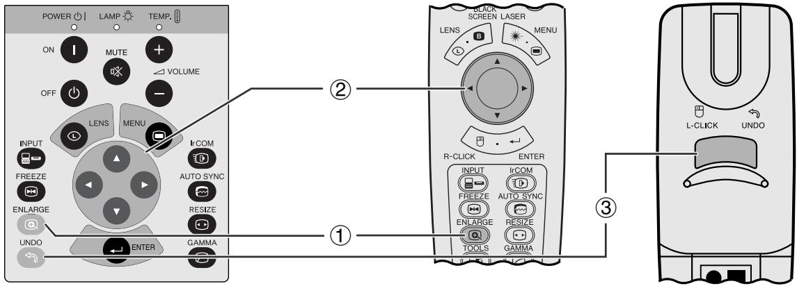
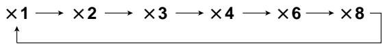
Projector
Remote control
This function allows you to magnify a specific portion of an image. This is useful when you want to display a detailed portion of the image.
On-screen Display


(Slide the MOUSE/ADJUSTMENT switch on the remote control to the ADJ.)

① Press ENLARGE. Each time ENLARGE is pressed, the image will be magnified.
(2) When the image is magnified, you can pan and scan around the image by using / / .
NOTE
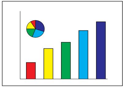
Each time ENLARGE is pressed, image magnification toggles as shown below.
- If the input signal is changed during digital image magnification, the image will return to × 1 . The input signal is changed
(a) when INPUT is pressed,
(b) when the input signal is interrupted, or
(c) when the input resolution and refresh rate changes.
(3) To return to × 1 , press UNDO.
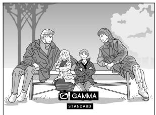
STANDARD
GAMMA 1
GAMMA 2
CUSTOM
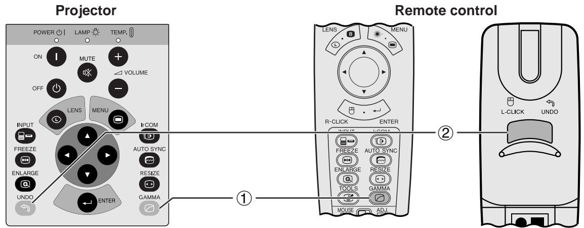
On-screen Display


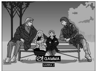


- Gamma is an image quality enhancement function that offers a richer image by brightening the darker portions of the image without altering the brightness of the brighter portions.
- Four gamma settings are available to allow for differences in the images played and in the brightness of the room.
- When you are watching images with frequent, dark scenes, such as a film or concert, or when you are watching images in a bright room, this feature makes the dark scenes easier to see and gives the impression of greater depth in the image.
Gamma Modes
| Selected Mode | Gamma mode |
| STANDARD | Standard picture without gamma correction. |
| GAMMA 1 | Brightens darker portions of image. |
| GAMMA 2 | Gives greater depth to darker portions of image. |
| CUSTOM | Allows you to adjust gamma value using Sharp Advanced Presentation Software. |
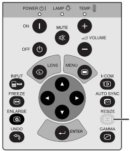
(Slide the MOUSE/ADJUSTMENT switch on the remote control to the ADJ. position.)
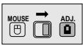
① Press GAMMA. Each time GAMMA is pressed, the gamma level toggles as shown on the left.
(2) To return to the standard image, press UNDO while “GAMMA” is displayed on the screen.
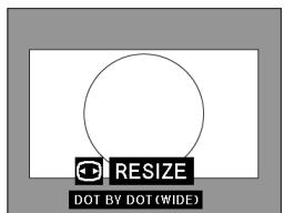
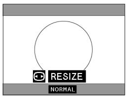
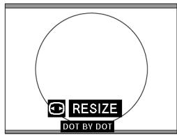
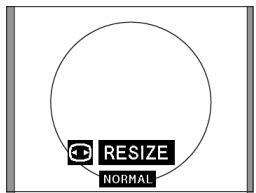
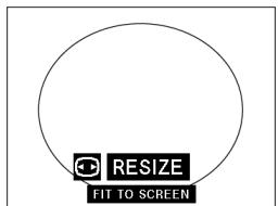
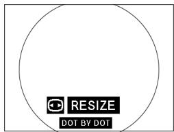
This function allows you to modify or customize the picture display mode to enhance the input image. Depending on the input signal, you can choose NORMAL, WIDE, DOT BY DOT, DOT BY DOT (WIDE), or FIT TO SCREEN image.
NOTE
Each time RESIZE is pressed, the picture mode changes as shown below.
Projector
RESIZE button
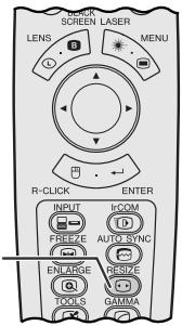
Remote control
EXAMPLE
| DTV | COMPUTER | ||
| MODE | 4:3 | 16:9 | SXGA |
| INPUT SIGNAL | 480 P | 720 P | |
| NORMAL | 1024 × 768 | 1024 × 576 | 960 × 768 |
| WIDE | 1024 × 576 | — | 1024 × 768 |
| DOT BY DOT | 640 × 480 | 1280 × 720 | 1280 × 1024 |
| DOT BY DOT (WIDE) | 853 × 480 | — | — |
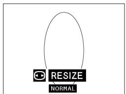
NORMAL
WIDE
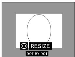
DOT BY DOT
DOT BY DOT (WIDE)
For DTV decoder RGB signal in 4:3 aspect ratio.

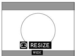


For DTV decoder RGB signal in 16:9 aspect ratio.

For COMPUTER/RGB signal without 4:3 aspect ratio.


NOTE
- "FIT TO SCREEN" is displayed only when SXGA signals that are not in 4:3 aspect ratio are input.
- DOT BY DOT mode displays images in their native resolution and not expanded to fit the LCD resolution.
- To return to NORMAL mode, press UNDO while "RESIZE" is displayed on the screen.
Projector
Remote control
Projected Image
GUI) On-screen Display
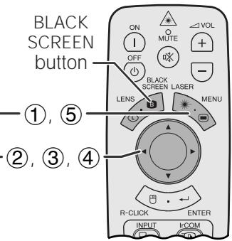
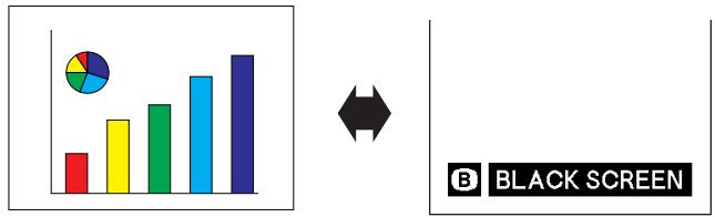
This function can be used to superimpose a black screen over the projected image.
Blacking out the Projected Image
Press BLACK SCREEN. "BLACK SCREEN" is displayed on the screen. To return to the original projected image, press BLACK SCREEN again.
NOTE
- To use the remote control to operate this function, slide the MOUSE/ADJUSTMENT switch to the MOUSE position before pressing BLACK SCREEN.
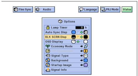
Turning off the On-screen Display
The On-screen Display ("BLACK SCREEN") that appears during black screen can be turned off. When "BLK SCRN Disp" is set to "■" in the GUI menu, "BLACK SCREEN" will not be displayed during function.
(Slide the MOUSE/ADJUSTMENT switch on the remote control to the ADJ. position.)
① Press MENU.
② Press / to select "Options".
③ Press to select "BLK SCRN Disp".
④ Press / to select “ ” to turn on or “ ” to turn off the function.
⑤ To exit from the GUI, press MENU.

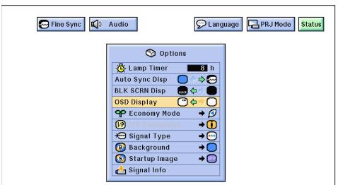
On-screen Display Override Function
Projector
Remote control
GUI) On-screen Display
This function allows you to turn off the on-screen messages that appear during "input select" and the "IrCOM" function. Once "OSD Display" is set to "○" in the GUI menu, the on-screen messages will not appear when INPUT and IrCOM are pressed.
(Slide the MOUSE/ADJUSTMENT switch on the remote control to the ADJ. position.)
① Press MENU.
② Press to select "Options".
③ Press / to select "OSD Display".
④ Press to select "O" to turn on or "O" to turn off the On-screen Display.
(5) To exit from the GUI, press MENU.
Projector
Remote control
GUI) On-screen Display
On-screen Display
Power OFF in 5 min.

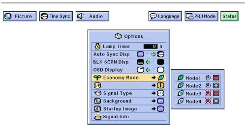
This function allows you to reduce the power consumption when the projector is off.
Economy Modes
| Selected mode | Automatic Power Shutoff | RS232C/Monitor out |
| Mode 1 | ON | OFF |
| Mode 2 | ON | ON |
| Mode 3 | OFF | OFF |
| Mode 4 | OFF | ON |
NOTE
- The projector is factory preset to Mode 2.
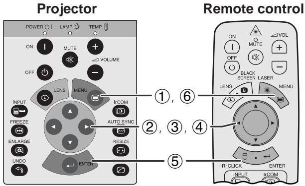
(Slide the MOUSE/ADJUSTMENT switch on the remote control to the ADJ. position.)
① Press MENU.
② Press to select "Options".
(3) Press / to select "Economy Mode", and then press .
④ Press / to select the desired mode.
⑤ Press ENTER to save the setting.
(6) To exit from the GUI, press MENU.
Automatic Power Shutdown Function
When no input signal is detected for more than 15 minutes, the projector will automatically shut off. The on-screen message on the left will appear five minutes before the power is automatically turned off.
CA
CAUTION
- Select Mode 2 or Mode 4 when using the Sharp Advanced Presentation Software (supplied).
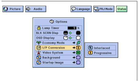
GUI) On-screen Display
This function allows you to select either an interlaced display or a progressive display of a video signal. The progressive display projects a smooth video image.
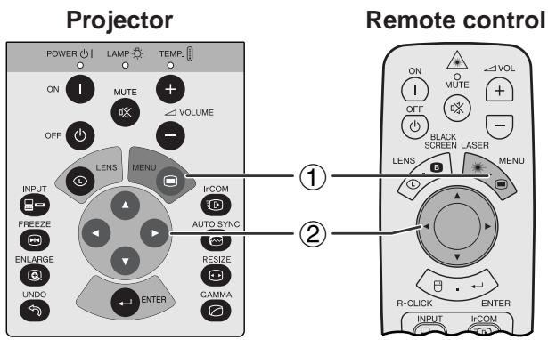
(Slide the MOUSE/ADJUSTMENT switch on the remote control to the ADJ. position.)
① Press MENU.
② Press to select "Options".
(3) Press / to select "I/P Conversion", and then press .
④ Press / to select "Interlaced" or "Progressive".
(5) Press ENTER to save the setting.
(6) To exit from the GUI, press MENU.

Checking the Lamp Usage Time
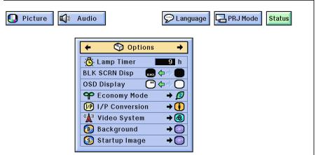
GUI) On-screen Display
This function allows you to check the accumulated lamp usage time.
(Slide the MOUSE/ADJUSTMENT switch on the remote control to the ADJ. position.)

① Press MENU.
② Press to select "Options". The lamp usage time will be displayed.
NOTE
- It is recommended that the lamp be replaced after approximately 2,000 hours of usage. See pages 48 and 49 for lamp replacement.
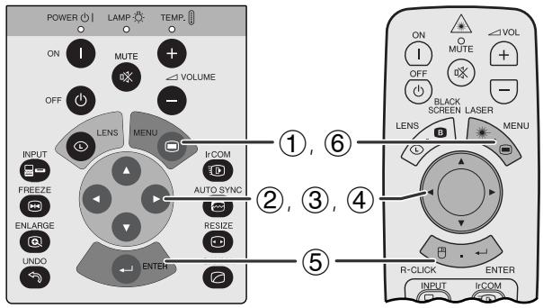
Projector
Remote control
teen Display
This function allows you to select the input signal type.
(Slide the MOUSE/ADJUSTMENT switch on the remote control to the ADJ. position.)
① Press MENU.
② Press to select "Options".
③ Press to select "Signal Type", and then press .
④ Press / to select "Computer/RGB" or "Component".
(5) Press ENTER to save the setting.
(6) To exit from the GUI, press MENU.

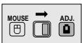
Checking the Input Signal
Projector
Remote control
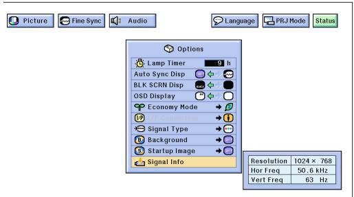
GUI) On-screen Display
This function allows you to check the current input signal information.
(Slide the MOUSE/ADJUSTMENT switch on the remote control to the ADJ. position.)
① Press MENU.
② Press to select "Options".
(3) Press / to select "Signal Info" to display the current input signal.
(4) To exit from the GUI, press MENU.
NOTE
- In VIDEO mode, the resolution and frequency settings will not be displayed.
GUI) On-screen Display
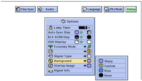
This function allows you to select the image displayed when no signal is being sent to the projector.
Description of Background Images
| Selected item | Background image |
| Sharp | SHARP default image |
| Custom | User customized image (i.e. company logo) |
| Blue | Blue screen |
| None | Black screen |
(Slide the MOUSE/ADJUSTMENT switch on the remote control to the ADJ. position.)
① Press MENU
(2) Press to select "Options".
(3) Press / to select "Background", and then press
(4) Press to select the background image you want to display on the screen.
⑤ Press ENTER to save the setting.
(6) To exit from the GUI, press MENU
NOTE
- By selecting "Custom", the projector can display a custom image (i.e. your company logo) as the background image. Custom image must be 256-color BMP file with a picture size of 1,024 × 768 or lower. Please see the Sharp Advanced Presentation Software operation manual for how to save (or change) a custom image.

Selecting a Startup Image
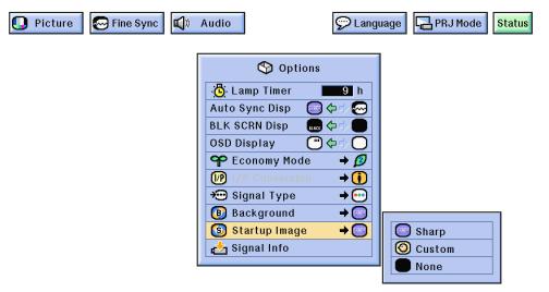
GUI) On-screen Display
- This function allows you to specify the image to be displayed upon the projector's startup.
- A custom image (i.e. your company logo) can be loaded on the projector via IrCOM or an RS-232C cable. See pages 14 and 25 in this operation manual, and also the supplied Sharp Advanced Presentation Software operation manual for detailed instructions.
Description of Startup Images
| Selected item | Startup image |
| Sharp | SHARP default image |
| Custom | User customized image (i.e. company logo) |
| None | Black screen |
(Slide the MOUSE/ADJUSTMENT switch on the remote control to the ADJ. position.)
① Press MENU
② Press to select "Options"
③ Press / to select "Startup Image", and then press .
④ Press / to select the startup image you want to display on the screen.
(5) Press ENTER to save the setting.
(6) To exit from the GUI, press MENU
NOTE
- By selecting "Custom", the projector can display a custom image (i.e. your company logo) as the startup image. Custom image must be 256-color BMP file with a picture size of 1,024 × 768 or lower. Please see the Sharp Advanced Presentation Software operation manual for how to save (or change) a custom image.
Projector
Remote control
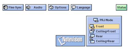
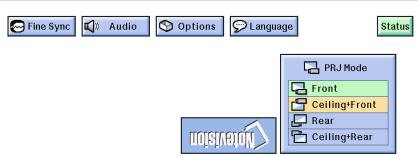
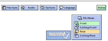
GUI) On-screen Display
When Selecting "Front"
When Selecting "Ceiling + Front"
When Selecting "Rear"
When Selecting "Ceiling + Rear"
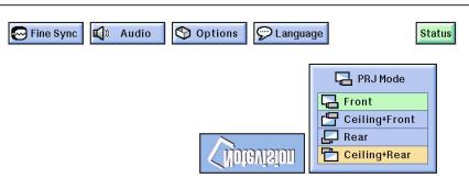
This projector is equipped with a reverse/invert image function which allows you to reverse or invert the projected image for various applications.
Description of Projected Images
| Selected item | Projected image |
| Front | Normal image |
| Ceiling + Front | Inverted image |
| Rear | Reversed image |
| Ceiling + Rear | Reversed and inverted image |
(Slide the MOUSE/ADJUSTMENT switch on the remote control to the ADJ. position.)

① Press MENU.
② Press to select "PRJ Mode".
(3) Press / to select the desired projection mode.
④ Press ENTER to save the setting.
⑤ To exit from the GUI, press MENU.
NOTE
- This function is used for the reversed image and ceiling-mount setups. See page 20 for these setups.
Projector
On-screen Display
Menu Window
Projector
Remote control
When selecting Sharp default image
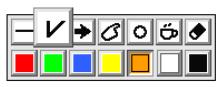
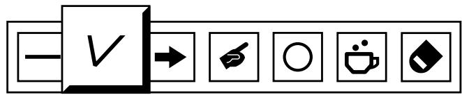
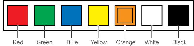
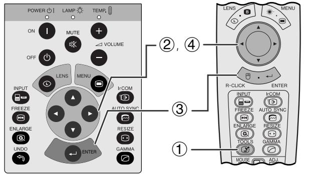
This projector is equipped with presentation tools. These will help you emphasize keypoints within your presentation.
(Slide the MOUSE/ADJUSTMENT switch on the remote control to the ADJ. position.)

① Press TOOLS to display the presentation tools menu window on the screen.
(2) Press / / to select the desired tool and color.
(3) Press ENTER to select it.
(4) Once the tool is displayed on the screen, press / / to move it around the screen.
⑤ Press ENTER to stamp the tool on the screen.
(6) Use UNDO to individually delete tools stamped on the screen.
NOTE
- You can stamp each tool as many times as you want on the screen.
- To clear all the stamped presentation tools on the screen, press / / to select "☑" and ENTER.
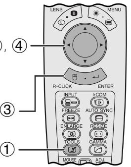
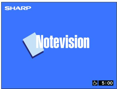
Displaying the break time
(Slide the MOUSE/ADJUSTMENT switch on the remote control to the ADJ. position.)

① Press TOOLS to display the presentation tools menu window on the screen.
② Press / / / to select "窗口" in the menu window.
(3) Press ENTER to start counting down the break time.
(4) Press to increase or to decrease the break time.
NOTE
- The break time is displayed against the background image selected in "Selecting a Startup Image". (See page 41.)
Projector
Remote control
(GUI) On-screen Display
(2)
(3)
This function can be used to display all the adjusted settings on the screen simultaneously.
(Slide the MOUSE/ADJUSTMENT switch on the remote control to the ADJ. position.)

① Press MENU.
② Press / to select "Status".
③ Press ENTER to display all the adjusted settings.
(4) To exit from the GUI, press MENU.

Maintenance & Troubleshooting

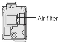
- This projector is equipped with two air filters to ensure the optimal operating condition of the projector.
- The air filters should be cleaned every 100 hours of use. Clean the filters more often when the projector is used in a dusty or smoky location.
- Have your nearest Authorized Sharp Industrial LCD Products Dealer or Service Center exchange the filter (PFILD0080CEZZ) when it is no longer possible to clean it.
Bottom View
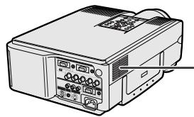
Side and Rear View
Air filter (not removable)
Cleaning and replacing the bottom air filter
| 1 Unplug the power cord. | 2 Remove the bottom filter cover. | 3 Remove the air filter. |
| Turn over the projector. Press the tab and lift open the filter cover in the direction of the arrow. | Grasp the air filter between your fingers and lift it out of the filter cover. | |
| 4 Clean the air filter. | 5 Replace the air filter. | 6 Replace the filter cover. |
| Clean the dust off the air filter and cover with a vacuum cleaner extension hose. | Place the air filter underneath the tabs on the filter frame. | Insert the tab on the end of the filter cover into the filter cover opening and press the filter cover into position. |
| Tab |
NOTE
- Be sure the filter cover is securely installed. The power will not turn on unless it is correctly installed.
Cleaning the side air filter (not removable)
If dust or dirt has collected inside the air filter, clean the filter with a vacuum cleaner extension hose.
NOTE
- The side air filter cannot be removed.

Maintenance Indicators
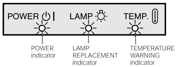
- The warning lights on the projector indicate problems inside the projector.
- There are two warning lights: a TEMPERATURE WARNING indicator which warns that the projector is too hot, and a LAMP REPLACEMENT indicator which lets you know when to change the lamp.
- If a problem occurs, either the TEMPERATURE WARNING indicator or the LAMP REPLACEMENT indicator will light up red. After turning off the power, follow the procedures given below.
| Maintenance Indicator | Condition | Problem | Possible Solution |
| TEMPERATURE WARNING indicator | The internal temperature is abnormally high. | •Blocked air intake. | •Relocate the projector to an area with proper ventilation. |
| •Clogged air filter. | •Clean the filter. (See page 46.) | ||
| •Cooling fan breakdown. •Internal circuit failure. | •Take the projector to your nearest Authorized Sharp Industrial LCD Products Dealer or Service Center for repair. | ||
| LAMP REPLACEMENT indicator | The lamp does not light up. | •Burnt-out lamp. •Lamp circuit failure. | •Carefully replace the lamp. (See pages 48 and 49.) •Take the projector to your nearest Authorized Sharp Industrial LCD Products Dealer or Service Center for repair. |
| POWER indicator | The POWER indicator flashes in red when the projector is on. | •The bottom filter cover is open. | •Securely install the bottom filter cover. |
NOTE
- If the TEMPERATURE WARNING indicator lights up, follow the above possible solutions and then wait until the projector has cooled down completely before turning the power back on. (At least 5 minutes.)
- If the power is turned off and then turned on again, as during a brief rest, the LAMP REPLACEMENT indicator may be triggered, preventing the power from going on. Should this occur, take the power cord out of the wall outlet and put it back in again.
Lamp
The lamp in this projector operates for approximately 2,000 cumulative hours, depending on the usage environment. It is recommended that the lamp be replaced after 1,900 cumulative hours of use or when you notice a significant deterioration of the picture and color quality. The lamp usage time can be checked with the On-screen Display (see page 39).
CAUTION
- Intense light hazard. Do not attempt to look into the aperture and lens while the projector is operating.
NOTE
- As the usage environment can vary significantly, the projector lamp may not operate for 2,000 hours.
It is recommended that the lamp be replaced after approximately 2,000 cumulative hours of use or when you notice a significant deterioration of the picture and color quality. Carefully change the lamp by following the steps below.
If the new lamp does not light after replacement, take your projector to the nearest Authorized Sharp Industrial LCD Products Dealer or Service Center for repair. Purchase a replacement lamp unit (lamp/cage module) of the current type BQC-XGNV6XU/1 from your nearest Authorized Sharp Industrial LCD Products Dealer or Service Center. Then carefully change the lamp by following the instructions below. If you wish, you may have the lamp replaced at your nearest Authorized Sharp Industrial LCD Products Dealer or Service Center.
IMPORTANT NOTE TO U.S. CUSTOMERS:
The lamp included with this projector is backed by a 90-day parts and labor limited warranty. All service of this projector under warranty, including lamp replacement, must be obtained through an Authorized Sharp Industrial LCD Products Dealer or Service Center. For the name of the nearest Authorized Sharp Industrial LCD Products Dealer or Service Center, please call toll-free: 1-800-BE-SHARP (1-800-237-4277). U.S.A. ONLY
Removing and installing the lamp unit
CAUTION
- Do not remove the lamp cage directly after operation of the projector. The lamp may be extremely hot. Wait at least one hour after the power cord is disconnected to allow the surface of the lamp cage to fully cool before removing the lamp cage.
- Be sure to remove the lamp cage by the handle. Be sure not to touch the glass surface of the lamp cage or the inside of the projector.
- To avoid injury to yourself and damage to the lamp, be sure to carefully follow the steps below.
- Before or after replacing the lamp, be sure to clean the air filters. See page 46 for cleaning the air filters.
| 1 Turn off the power. | 2 Disconnect the power cord. | 3 Slide the lamp cage cover out. |
| Press POWER OFF. Wait until the cooling fan stops. | Unplug the power cord from the AC socket. | Turn over the projector and un-fasten the user service screw that secures the lamp cage cover. Then slide the cover in the direction of the arrow. |
| OFF OR OFF | User service screw | |
| 4 Remove the lamp cage. | 5 Replace the lamp cage (after changing the lamp). | 6 Slide the lamp cage cover in. |
| Remove the securing screws from the lamp cage. Hold the lamp cage by the handle and pull it towards you. | Press the lamp cage firmly into the lamp cage compartment. Fasten the securing screws. | Slide the lamp cage cover in the direction of the arrow. Then fasten the user service screw. |
| Securing screw Sequencing screws | User service screw |

Resetting the lamp timer
| 1 Connect the power cord. | 2 Reset the lamp timer. | |
| Plug the power cord into the AC socket of the projector. | While pressing▼, ▷ and ENTER on the projector, press POWER ON on the projector. | "LAMP 0000H" is displayed, indicating that the lamp timer is reset. |
NOTE
- Reset the lamp timer only after replacing the lamp.

Using the Kensington Lock
Kensington Security Standard connector
This projector has a Kensington Security Standard connector for use with a Kensington MicroSaver Security System. Refer to the information that came with the system for instructions on how to use it to secure the projector.

Troubleshooting
| Problem | Check |
| No picture and no sound. | • Projector power cord is not plugged into the wall outlet. • The bottom filter cover is not securely installed. • Selected input is wrong. (See pages 17.) • Cables improperly connected to rear panel of the projector. (See pages 11-15.) • Remote control batteries have run down. (See page 8.) • Remote control's MOUSE/ADJUSTMENT switch is set to MOUSE. |
| Sound is heard but no picture appears. | • Cables improperly connected to rear panel of the projector. (See pages 11-15.) • "Contrast" and "Bright" adjustments are set to minimum position. (See page 27.) • On-screen Display ("BLACK SCREEN") is turned off and Black Screen function is turned on, creating a black image. (See page 37.) |
| Color is faded or poor. | • "Color" and "Tint" adjustments are not correct. (See page 27.) |
| Picture is blurred. | • Adjust the focus. (See page 19.) • Projection distance is too long or too short to allow for proper focus. (See page 18.) |
| Picture appears but no sound is heard. | • Cables improperly connected to rear panel of the projector. (See pages 11-15.) • Volume is set to minimum. (See page 17.) |
| An unusual sound is occasionally heard from the cabinet. | • If the picture is normal, the sound is due to cabinet shrinkage caused by temperature changes. This will not affect operation or performance. |
| Maintenance indicator lights up. | • Refer to "Lamp/Maintenance Indicators" on page 47. |
| Data cannot be received via IrCOM. | • Distance and angle between the projector and transmitting device are out of the designated range. (See page 25.) • Refer to the operation manual of the transmitting device. • Refer to the section "Troubleshooting" in the operation manual of the supplied software. |
| Picture noise appears. | • Adjust the phase setting. (See page 29.) • Noise may appear when used with certain computers. Set the NOISE FILTER to ON using the RS-232C command. (See pages 52 and 53.) |
| 480P images do not appear. | • Set the resolution mode to 480P. (See page 32.) |
| Color is distorted. | • Change the input signal type. (See page 40.) |
| Lens comes off. | • Align the mark on the lens with the corresponding mark on the projector, push the lens firmly in place, and rotate to the right. |

Appendix

Optional Lenses

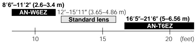
Wide-zoom lens AN-W6EZ

Tele-zoom lens AN-T6EZ
Optional wide and telephoto lenses from Sharp are also available for specialized application. Please see your local Sharp Industrial LCD Products Dealer for details on the AN-W6EZ and AN-T6EZ. (Refer to the lens operation manual when attaching the lens.)
100" Screen Project Distance

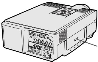
Transporting the Projector
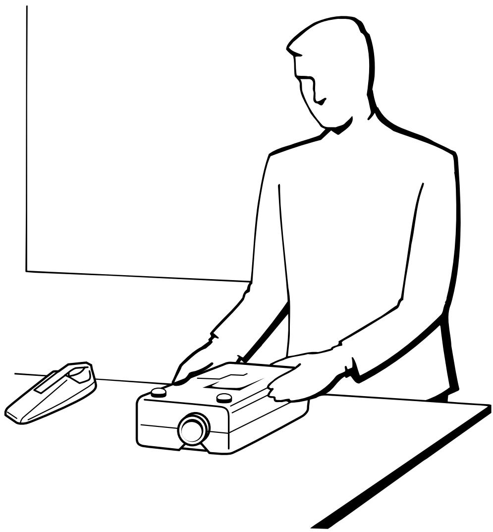
Using the Carrying Handle
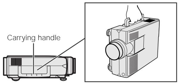
When transporting the projector, carry it by the carrying handle on the side.
CAUTION
- Always put on the lens cap to prevent damage to the lens when transporting the projector.
- Do not lift or carry the projector by the lens or the lens cap as this may damage the lens.

Analog Computer 1 and 2 Signal Input Ports: 15-pin mini D-sub female connector
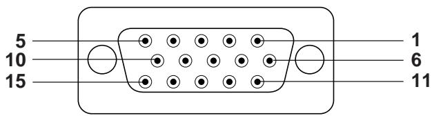
Computer Input
Analog
- Video input (red)
- Video input (green/sync on green)
- Video input (blue)
- Reserve input 1
- Composite sync
- Earth (red)
- Earth (green/sync on green)
-
Earth (blue)
-
Not connected
- GND
- GND
- Bi-directional data
- Horizontal sync signal
- Vertical sync signal
- Data clock
RS-232C Port: 9-pin D-sub male connector of the DIN-D-sub RS-232C cable
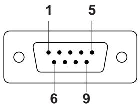
| Pin No. | Signal | Name | I/O | Reference |
| 1 | CD | Not connected | ||
| 2 | RD | Receive Data | Input | Connected to internal circuit |
| 3 | SD | Send Data | Output | Connected to internal circuit |
| 4 | ER | Not connected | ||
| 5 | SG | Signal Ground | Connected to internal circuit | |
| 6 | DR | Data Set Ready | Output | Not connected |
| 7 | RS | Request to Send | Output | Connected to internal circuit |
| 8 | CS | Clear to Send | Input | Connected to internal circuit |
| 9 | CI | Not connected |
RS-232C Terminal: 9-pin mini DIN connector
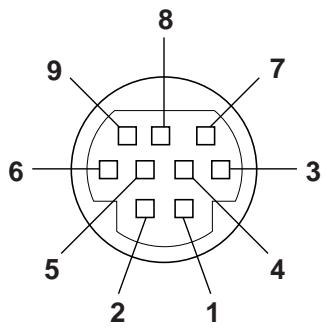
| Pin No. | Signal | Name | I/O | Reference |
| 1 | VCC | +3.3V (Reserved) | Output | Not connected |
| 2 | RD | Receive Data | Input | Connected to internal circuit |
| 3 | SD | Send Data | Output | Connected to internal circuit |
| 4 | EXIR | Detector of Option Unit (Reserved) | Input | Not connected |
| 5 | SG | Signal Ground | Connected to internal circuit | |
| 6 | ERX | IR Receive Signal from IR Amplifier (Reserved) | Input | Not connected |
| 7 | RS | Request to Send | Output | Connected to internal circuit |
| 8 | CS | Clear to Send | Input | Connected to internal circuit |
| 9 | ETX | IR Transmit Signal (Reserved) | Output | Not connected |
PC control
A computer can be used to control the projector by connecting an RS-232C cable (cross type, sold separately) to the projector. (See page 14 for connection.)
Communication conditions
Set the serial port settings of the computer to match that of the table on the next page.
Signal format: Conforms to RS-232C standard.
Baud rate: 9,600 bps
Data length: 8 bits
Parity bit: NON
Stop bit: 1 bit
Flow control: None
Basic format
Commands from the computer are sent in the following order: command, parameter, and return code. After the projector processes the command from the computer, it sends a response code to the computer.
Command format
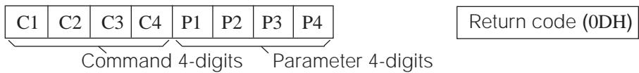
Response code format
Normal response
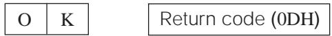
Problem response (communication error or incorrect command)

When more than one code is being sent, send each command only after the OK response code for the previous command from the projector is verified.
NOTE
- When using the computer control function of the projector, the projector operating status cannot be read to the computer. Therefore, confirm the status by transmitting the display commands for each adjustment menu and checking the status with the On-screen Display. If the projector receives a command other than a menu display command, it will execute the command without displaying the On-screen Display.
Commands
EXAMPLE
- When "BRIGHT" of INPUT 1 IMAGE ADJUSTMENT is set to -10.
Computer
| R | A | B | R | - | - | 1 | 0 | ↓ |
| CONTROL ITEM | COMMAND | PARAMETER | CONTROL CONTENTS | ||||||
| C1 | C2 | C3 | C4 | P1 | P2 | P3 | P4 | ||
| AUTO POWER OFF | A | P | O | W | - | - | - | 0 | AUTO POWER OFF |
| A | P | O | W | - | - | - | 1 | AUTO POWER ON | |
| POWER SETTING | P | O | W | R | - | - | - | 0 | POWER OFF (STANDBY) |
| P | O | W | R | - | - | - | 1 | POWER ON | |
| INPUT SWITCHING | I | V | E | D | - | - | - | 1 | VIDEO |
| I | R | G | B | - | - | - | 1 | INPUT1 | |
| I | R | G | B | - | - | - | 2 | INPUT2 | |
| I | C | O | M | - | - | - | 1 | IrCOM1 | |
| I | C | O | M | - | - | - | 2 | IrCOM2 | |
| INPUT CHECK | I | C | H | K | - | - | - | 0 | INPUT CHECK |
| LENS ADJUSTMENT | L | N | F | O | - | * | * | * | LENS FOCUS (-30 - +30) |
| L | N | Z | O | - | * | * | * | LENS ZOOM (-30 - +30) | |
| K | E | Y | S | * | * | * | * | KEYSTONE (-127 - +127) | |
| CONTROL ITEM | COMMAND | PARAMETER | CONTROL CONTENTS | ||||||
| C1 | C2 | C3 | C4 | P1 | P2 | P3 | P4 | ||
| LANGUAGE SELECTION | M | E | L | A | _ | _ | _ | 1 | ENGLISH |
| M | E | L | A | _ | _ | _ | 2 | DEUTSCH | |
| M | E | L | A | _ | _ | _ | 3 | ESPAÑOL | |
| M | E | L | A | _ | _ | _ | 4 | NEDERLANDS | |
| M | E | L | A | _ | _ | _ | 5 | FRANÇAIS | |
| M | E | L | A | _ | _ | _ | 6 | ITALIANO | |
| M | E | L | A | _ | _ | _ | 7 | SVENSKA | |
| M | E | L | A | _ | _ | _ | 8 | 日本語 | |
| M | E | L | A | _ | _ | _ | 9 | PORTUGUES | |
| M | E | L | A | _ | _ | 1 | 0 | 汉语 | |
| M | E | L | A | _ | _ | 1 | 1 | 한국어 | |
| VIDEO SYSTEM SELECTION | M | E | S | Y | _ | _ | _ | 1 | AUTO |
| M | E | S | Y | _ | _ | _ | 2 | PAL (50/60 Hz) | |
| M | E | S | Y | _ | _ | _ | 3 | SECAM | |
| M | E | S | Y | _ | _ | _ | 4 | NTSC 4.43 | |
| M | E | S | Y | _ | _ | _ | 5 | NTSC 3.58 | |
| VIDEO IMAGE ADJUSTMENT | V | A | P | I | _ | * | * | * | CONTRAST (-30 - +30) |
| V | A | B | R | _ | * | * | * | BRIGHT (-30 - +30) | |
| V | A | C | O | _ | * | * | * | COLOR (-30 - +30) | |
| V | A | T | I | _ | * | * | * | TINT (-30 - +30) | |
| V | A | S | H | _ | * | * | * | SHARPNESS (-30 - +30) | |
| V | A | R | E | _ | _ | _ | 1 | RESET | |
| V | A | R | D | _ | * | * | * | RED (-30 - +30) | |
| V | A | B | E | _ | * | * | * | BLUE (-30 - +30) | |
| V | A | R | E | _ | _ | _ | 0 | VIDEO DISPLAY | |
| V | A | R | E | _ | _ | _ | 1 | RESET | |
| BACKGROUND SELECTION | I | M | B | G | _ | _ | _ | 1 | SHARP |
| I | M | B | G | _ | _ | _ | 2 | CUSTOM | |
| I | M | B | G | _ | _ | _ | 3 | BLUE | |
| I | M | B | G | _ | _ | _ | 4 | NONE | |
| STARTUP IMAGE SELECTION | I | M | S | I | _ | _ | _ | 1 | SHARP |
| I | M | S | I | _ | _ | _ | 2 | CUSTOM | |
| I | M | S | I | _ | _ | _ | 3 | NONE | |
| VOLUME ADJUSTMENT | V | O | L | A | _ | _ | * | * | VOLUME (00 - 60) |
| M | U | T | E | _ | _ | _ | 0 | MUTE OFF | |
| M | U | T | E | _ | _ | _ | 1 | MUTE ON | |
| AUDIO ADJUSTMENT | A | A | B | L | _ | * | * | * | BALANCE (-30 - +30) |
| A | A | T | E | _ | * | * | * | TREBLE (-30 - +30) | |
| A | A | B | A | _ | * | * | * | BASS (-30 - +30) | |
| A | A | R | E | _ | _ | _ | 0 | AUDIO DISPLAY | |
| A | A | R | E | _ | _ | _ | 1 | RESET | |
| INPUT 1 IMAGE ADJUSTMENT | R | A | P | I | _ | * | * | * | CONTRAST (-30 - +30) |
| R | A | B | R | _ | * | * | * | BRIGHT (-30 - +30) | |
| R | A | R | D | _ | * | * | * | RED (-30 - +30) | |
| R | A | B | E | _ | * | * | * | BLUE (-30 - +30) | |
| R | A | R | E | _ | _ | _ | 0 | INPUT 1 DISPLAY | |
| R | A | C | O | _ | * | * | * | COLOR (-30 - +30) | |
| R | A | T | I | _ | * | * | * | TINT (-30 - +30) | |
| R | A | S | H | _ | * | * | * | SHARPNESS (-30 - +30) | |
| R | A | R | E | _ | _ | _ | 1 | RESET | |
| INPUT 2 IMAGE ADJUSTMENT | R | B | P | I | _ | * | * | * | CONTRAST (-30 - +30) |
| R | B | B | R | _ | * | * | * | BRIGHT (-30 - +30) | |
| R | B | R | D | _ | * | * | * | RED (-30 - +30) | |
| R | B | B | E | _ | * | * | * | BLUE (-30 - +30) | |
| R | B | R | E | _ | _ | _ | 0 | INPUT 2 DISPLAY | |
| R | B | C | O | _ | * | * | * | COLOR (-30 - +30) | |
| R | B | T | I | _ | * | * | * | TINT (-30 - +30) | |
| R | B | S | H | _ | * | * | * | SHARPNESS (-30 - +30) | |
| R | B | R | E | _ | _ | _ | 1 | RESET | |
| INPUT AUTO SYNCHRONIZATION | A | A | D | J | _ | _ | _ | 0 | AUTO SYNC OFF |
| A | A | D | J | _ | _ | _ | 1 | AUTO SYNC ON | |
| A | D | J | S | _ | _ | _ | 1 | AUTO SYNC START | |
| CONTROL ITEM | COMMAND | PARAMETER | CONTROL CONTENTS | ||||||
| C1 | C2 | C3 | C4 | P1 | P2 | P3 | P4 | ||
| INPUT ADJUSTMENT | I | N | C | L | * | * | * | * | CLOCK (-150 - +150) |
| I | N | P | H | _ | * | * | * | PHASE (-60 - +60) | |
| I | A | H | P | * | * | * | * | H-POS (-150 - +150) | |
| I | A | V | P | _ | * | * | * | V-POS (-60 - +60) | |
| I | A | R | E | _ | _ | _ | 0 | COMPUTER INPUT DISPLAY | |
| I | A | R | E | _ | _ | _ | 1 | RESET | |
| SCREEN SETTING | I | M | D | I | _ | _ | _ | 0 | OSD DISPLAY OFF |
| I | M | D | I | _ | _ | _ | 1 | OSD DISPLAY ON | |
| I | M | R | E | _ | _ | _ | 0 | REVERSE OFF | |
| I | M | R | E | _ | _ | _ | 1 | REVERSE ON | |
| I | M | I | N | _ | _ | _ | 0 | INVERT OFF | |
| I | M | I | N | _ | _ | _ | 1 | INVERT ON | |
| I | M | A | S | _ | _ | _ | 0 | AUTO SYNC DISPLAY OFF | |
| I | M | A | S | _ | _ | _ | 1 | AUTO SYNC DISPLAY ON | |
| I | M | I | P | _ | _ | _ | 0 | I/P CONVERSION INTERLACED | |
| I | M | I | P | _ | _ | _ | 1 | I/P CONVERSION PROGRESSIVE | |
| INPUT1 SIGNAL TYPE SELECTION | I | A | S | I | _ | _ | _ | 1 | RGB |
| I | A | S | I | _ | _ | _ | 2 | COMPONENT | |
| INPUT2 SIGNAL TYPE SELECTION | I | B | S | I | _ | _ | _ | 1 | RGB |
| I | B | S | I | _ | _ | _ | 2 | COMPONENT | |
| INPUT GAMMA SELECTION | G | A | M | R | _ | _ | _ | 1 | STANDARD |
| G | A | M | R | _ | _ | _ | 2 | GAMMA1 | |
| G | A | M | R | _ | _ | _ | 3 | GAMMA2 | |
| G | A | M | R | _ | _ | _ | 4 | CUSTOM | |
| VIDEO GAMMA SELECTION | G | A | M | V | _ | _ | _ | 1 | STANDARD |
| G | A | M | V | _ | _ | _ | 2 | GAMMA1 | |
| G | A | M | V | _ | _ | _ | 3 | GAMMA2 | |
| G | A | M | V | _ | _ | _ | 4 | CUSTOM | |
| VIDEO CONFIRMATION | S | Y | S | E | _ | _ | _ | 0 | DISPLAY |
| BLACK SCREEN | I | M | B | K | _ | _ | _ | 0 | BLACK SCREEN OFF |
| I | M | B | K | _ | _ | _ | 1 | BLACK SCREEN ON | |
| I | M | B | O | _ | _ | _ | 0 | BLACK SCREEN DISPLAY OFF | |
| I | M | B | O | _ | _ | _ | 1 | BLACK SCREEN DISPLAY ON | |
| SCREEN MODE MEMORY | M | E | M | S | _ | _ | _ | * | SAVE SETTING (1-7) |
| M | E | M | L | _ | _ | _ | * | SELECT SETTING (1-7) | |
| INPUT1 RESIZE | R | A | S | R | _ | _ | _ | 1 | NORMAL |
| R | A | S | R | _ | _ | _ | 2 | WIDE/FIT TO SCREEN | |
| R | A | S | R | _ | _ | _ | 3 | DOT BY DOT | |
| R | A | S | R | _ | _ | _ | 4 | DOT BY DOT (WIDE) | |
| INPUT2 RESIZE | R | B | S | R | _ | _ | _ | 1 | NORMAL |
| R | B | S | R | _ | _ | _ | 2 | WIDE/FIT TO SCREEN | |
| R | B | S | R | _ | _ | _ | 3 | DOT BY DOT | |
| R | B | S | R | _ | _ | _ | 4 | DOT BY DOT (WIDE) | |
| VIDEO RESIZE | R | A | S | V | _ | _ | _ | 1 | NORMAL |
| R | A | S | V | _ | _ | _ | 2 | WIDE | |
| R | A | S | V | _ | _ | _ | 3 | DOT BY DOT | |
| NOISE FILTER | N | F | I | L | _ | _ | _ | 0 | FILTER OFF |
| N | F | I | L | _ | _ | _ | 1 | FILTER ON | |
NOTE
- If a dash () appears in the parameter column, enter a space. If an asterisk (^) appears, enter a value in the range indicated in brackets under CONTROL CONTENTS.
- INPUT ADJUSTMENT can only be set in the displayed computer mode.
- Noise may appear when used with certain computers. Set the NOISE FILTER to ON using the RS-232C command.

Specifications of wired remote control input
- 3.50 minijack
External: +5V (1 A)
Internal: GND
Function and transmission codes
| No. | Control Item | System Code | Data Code | External Code | ||||||||||||
| (Function) | C1 | C2 | C3 | C4 | C5 | C6 | C7 | C8 | C9 | C10 | C11 | C12 | C13 | C14 | C15 | |
| 1 | POWER ON | 1 | 0 | 1 | 1 | 0 | 0 | 1 | 1 | 0 | 1 | 0 | 1 | 0 | 1 | 0 |
| 2 | POWER OFF | 1 | 0 | 1 | 1 | 0 | 0 | 1 | 1 | 0 | 1 | 0 | 0 | 1 | 1 | 0 |
| 3 | VOLUME - | 1 | 0 | 1 | 1 | 0 | 1 | 0 | 1 | 0 | 1 | 0 | 0 | 0 | 1 | 0 |
| 4 | VOLUME + | 1 | 0 | 1 | 1 | 0 | 0 | 0 | 1 | 0 | 1 | 0 | 0 | 0 | 1 | 0 |
| 5 | MUTE | 1 | 0 | 1 | 1 | 0 | 1 | 1 | 1 | 0 | 1 | 0 | 0 | 0 | 1 | 0 |
| 6 | MENU | 1 | 0 | 1 | 1 | 0 | 0 | 0 | 1 | 0 | 0 | 0 | 1 | 1 | 1 | 0 |
| 7 | LENS | 1 | 0 | 1 | 1 | 0 | 1 | 1 | 0 | 1 | 0 | 0 | 0 | 1 | 1 | 0 |
| 8 | TOOLS | 1 | 0 | 1 | 1 | 0 | 0 | 1 | 0 | 1 | 0 | 1 | 1 | 1 | 1 | 0 |
| 9 | BLACK SCREEN | 1 | 0 | 1 | 1 | 0 | 1 | 0 | 0 | 1 | 0 | 1 | 1 | 0 | 1 | 0 |
| 10 | ENTER | 1 | 0 | 1 | 1 | 0 | 1 | 1 | 1 | 0 | 1 | 0 | 1 | 0 | 1 | 0 |
| 11 | UNDO | 1 | 0 | 1 | 1 | 0 | 1 | 0 | 0 | 1 | 1 | 0 | 1 | 0 | 1 | 0 |
| No. | Control Item | System Code | Data Code | External Code | ||||||||||||
| (Function) | C1 | C2 | C3 | C4 | C5 | C6 | C7 | C8 | C9 | C10 | C11 | C12 | C13 | C14 | C15 | |
| 12 | IrCOM | 1 | 0 | 1 | 1 | 0 | 1 | 1 | 1 | 0 | 1 | 1 | 0 | 1 | 1 | 0 |
| 13 | INPUT | 1 | 0 | 1 | 1 | 0 | 1 | 1 | 0 | 0 | 1 | 0 | 0 | 0 | 1 | 0 |
| 14 | FREEZE | 1 | 0 | 1 | 1 | 0 | 1 | 0 | 1 | 1 | 0 | 0 | 0 | 1 | 1 | 0 |
| 15 | ENLARGE | 1 | 0 | 1 | 1 | 0 | 1 | 0 | 1 | 1 | 0 | 1 | 1 | 0 | 1 | 0 |
| 16 | AUTO SYNC | 1 | 0 | 1 | 1 | 0 | 0 | 1 | 0 | 1 | 1 | 1 | 1 | 1 | 1 | 0 |
| 17 | ADJUST▲ | 1 | 0 | 1 | 1 | 0 | 0 | 0 | 1 | 1 | 1 | 0 | 0 | 1 | 1 | 0 |
| 18 | ADJUST▼ | 1 | 0 | 1 | 1 | 0 | 1 | 0 | 1 | 1 | 1 | 0 | 0 | 1 | 1 | 0 |
| 19 | ADJUST▲ | 1 | 0 | 1 | 1 | 0 | 0 | 0 | 0 | 0 | 1 | 0 | 1 | 0 | 1 | 0 |
| 20 | ADJUST▲ | 1 | 0 | 1 | 1 | 0 | 1 | 1 | 1 | 1 | 0 | 0 | 1 | 0 | 1 | 0 |
| 21 | RESIZE | 1 | 0 | 1 | 1 | 0 | 0 | 1 | 1 | 1 | 1 | 0 | 1 | 0 | 1 | 0 |
| 22 | GAMMA | 1 | 0 | 1 | 1 | 0 | 0 | 0 | 0 | 0 | 0 | 0 | 1 | 0 | 1 | 0 |
NOTE
- To operate the mouse, left-click and right-click functions through the wired remote control input, connect the cable from the WIRED REMOTE control input terminal on the projector to the remote control. The codes for these functions are complex and are, therefore, not listed here.
Wired remote control function code
LSB
MSB
| C1 | System Code | C5 | C6 | Data Code | C13 | C14 | C15 |
| 1 | 0 | 1 | 0 | * | * | 1 | 0 |
- System codes C1 to C5 are fixed at "10110".
- Codes C14 and C15 are reverse confirmation bits, with "10" indicating "Front" and "01" indicating "Rear".
Sharp remote control signal format
Transmission format: 15-bit format
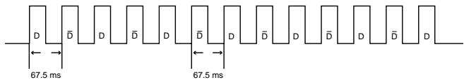
Wave form of output signal: Output using Pulse Position Modulation
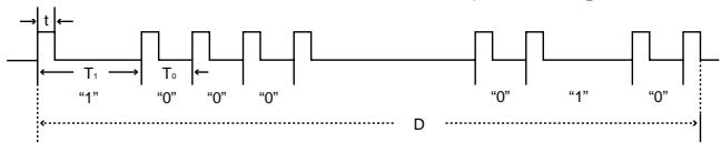
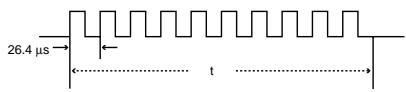
- t = 264 s
- Pulse carrier frequency = 455/12 kHz
- To = 1.05 ms
- Duty ratio = 1:1
- T1 = 2.10 ms
Transmission control code
15 bit
| C1 | C2 | C3 | C4 | C5 | C6 | C7 | C8 | C9 | C10 | C11 | C12 | C13 | C14 | C15 |
| System Address | Function Key Data Bit | Data Expansion | Mask | Data Determination | ||||||||||
| D to D Common Data Bit | Reverse in D | |||||||||||||
Example of Reverse D to
| D | C1 | C2 | C3 | C4 | C5 | C6 | C7 | C8 | C9 | C10 | C11 | C12 | C13 | C14 | C15 |
| 1 | 0 | 1 | 1 | 0 | 1 | 0 | 0 | 0 | 0 | 0 | 0 | 0 | 1 | 0 |
| C1 | C2 | C3 | C4 | C5 | C6 | C7 | C8 | C9 | C10 | C11 | C12 | C13 | C14 | C15 |
| 1 | 0 | 1 | 1 | 0 | 0 | 1 | 1 | 1 | 1 | 1 | 1 | 1 | 0 | 1 |

The computer output signal timing of different types of computer signals are shown below for reference.
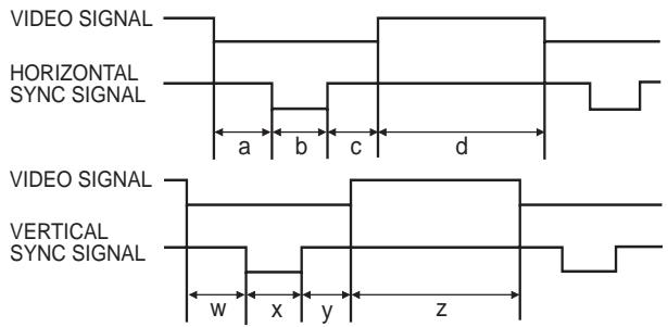
For IBM and compatibles
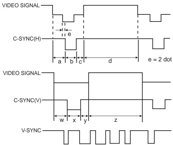
For Macintosh Series
The following is a list of compatible VESA standards. Please note that this projector also accepts signals outside of the VESA standards.
NOTE
- Depending on the mode selected, the projector may clearly display images under 130Hz .
| MODE | VIDEO | HSYNC | VSYNC | |||||||||||||||||||
| FRONTPORCHa | SYNCb | BACKPORCHc | VIDEOPERIODd | 1H(a+b+c+d) | 1dot | 1/H | 1/dot | LEVEL | FRONTPORCHw | SYNCx | BACKPORCHy | VIDEOPERIODz | 1V(w+x+y+z) | 1/V | LEVEL | |||||||
| dot | line | LEVEL | TYPE | dot | dot | dot | dot | dot | μs | ns | kHz | MHz | H | H | H | H | H | ms | Hz | |||
| VGA | VESASTandard | 640 | 350 | R·G·B | 32 | 64 | 96 | 640 | 832 | 26.4 | 31.7 | 37.861 | 31.500 | TTL | 32 | 3 | 60 | 350 | 445 | 11.8 | 85.080 | TTL |
| 640 | 400 | 32 | 64 | 96 | 640 | 832 | 26.4 | 31.7 | 37.861 | 31.500 | 1 | 3 | 41 | 400 | 445 | 11.8 | 85.080 | |||||
| 720 | 400 | 36 | 72 | 108 | 720 | 936 | 26.4 | 28.2 | 37.927 | 35.500 | 1 | 3 | 42 | 400 | 446 | 11.8 | 85.039 | |||||
| IndustryStandard | 640 | 480 | 8 | 96 | 40 | 640 | 800 | 31.8 | 39.7 | 31.469 | 25.175 | 2 | 2 | 25 | 480 | 525 | 16.7 | 59.940 | ||||
| VESASTandard | 640 | 480 | 16 | 40 | 120 | 640 | 832 | 26.4 | 31.7 | 37.861 | 31.500 | 1 | 3 | 20 | 480 | 520 | 13.7 | 72.809 | ||||
| 640 | 480 | 16 | 64 | 120 | 640 | 840 | 26.7 | 31.7 | 37.500 | 31.500 | 1 | 3 | 16 | 480 | 500 | 13.3 | 75.000 | |||||
| 640 | 480 | 56 | 56 | 80 | 640 | 832 | 23.1 | 27.8 | 43.269 | 36.000 | 1 | 3 | 25 | 480 | 509 | 11.8 | 85.008 | |||||
| SVGA | VESASTandard | 800 | 600 | 24 | 72 | 128 | 800 | 1,024 | 28.4 | 27.8 | 35.156 | 36.000 | 1 | 2 | 22 | 600 | 625 | 17.8 | 56.250 | |||
| 800 | 600 | 40 | 128 | 88 | 800 | 1,056 | 26.4 | 25.0 | 37.879 | 40.000 | 1 | 4 | 23 | 600 | 628 | 16.6 | 60.317 | |||||
| VESASTandard | 800 | 600 | 56 | 120 | 64 | 800 | 1,040 | 20.8 | 20.0 | 48.077 | 50.000 | 37 | 6 | 23 | 600 | 666 | 13.9 | 72.188 | ||||
| 800 | 600 | 16 | 80 | 160 | 800 | 1,056 | 21.3 | 20.2 | 46.875 | 49.500 | 1 | 3 | 21 | 600 | 625 | 13.3 | 75.000 | |||||
| 800 | 600 | 32 | 64 | 152 | 800 | 1,048 | 18.6 | 17.8 | 53.674 | 56.250 | 1 | 3 | 27 | 600 | 631 | 11.8 | 85.061 | |||||
| XGA | IndustryStandard | 1,024 | 768 | 8 | 176 | 56 | 1,024 | 1,264 | 28.2 | 22.3 | 35.522 | 44.900 | 0 | 4 | 20 | 768 | 817 | 23.0 | 43.479 | |||
| VESASTandard | 1,024 | 768 | 24 | 136 | 160 | 1,024 | 1,344 | 20.7 | 15.4 | 48.363 | 65.000 | 3 | 6 | 29 | 768 | 806 | 16.7 | 60.004 | ||||
| VESASTandard | 1,024 | 768 | 24 | 136 | 144 | 1,024 | 1,328 | 17.7 | 13.3 | 56.476 | 75.000 | 3 | 6 | 29 | 768 | 806 | 14.3 | 70.069 | ||||
| 1,024 | 768 | 16 | 96 | 176 | 1,024 | 1,312 | 16.7 | 12.7 | 60.023 | 78.750 | 1 | 3 | 28 | 768 | 800 | 13.3 | 75.029 | |||||
| 1,024 | 768 | 48 | 96 | 208 | 1,024 | 1,376 | 14.6 | 10.6 | 68.677 | 94.500 | 1 | 3 | 36 | 768 | 808 | 11.8 | 84.997 | |||||
| SXGA | VESASTandard | 1,152 | 864 | 64 | 128 | 256 | 1,152 | 1,600 | 14.8 | 9.3 | 67.500 | 108.000 | 1 | 3 | 32 | 864 | 900 | 13.3 | 75.000 | |||
| 1,280 | 960 | 96 | 112 | 312 | 1,280 | 1,800 | 16.7 | 9.3 | 60.000 | 108.000 | 1 | 3 | 36 | 960 | 1,000 | 16.7 | 60.000 | |||||
| 1,280 | 960 | 64 | 160 | 224 | 1,280 | 1,728 | 11.6 | 6.7 | 85.938 | 148.500 | 1 | 3 | 47 | 960 | 1,011 | 11.8 | 85.002 | |||||
| 1,280 | 1,024 | 48 | 112 | 248 | 1,280 | 1,688 | 15.6 | 9.3 | 63.981 | 108.000 | 1 | 3 | 38 | 1,024 | 1,066 | 16.7 | 60.020 | |||||
| 1,280 | 1,024 | 16 | 144 | 248 | 1,280 | 1,688 | 12.5 | 7.4 | 79.976 | 135.000 | 1 | 3 | 38 | 1,024 | 1,066 | 13.3 | 75.025 | |||||
| 1,280 | 1,024 | 64 | 160 | 224 | 1,280 | 1,728 | 11.0 | 6.3 | 91.146 | 157.500 | 1 | 3 | 44 | 1,024 | 1,072 | 11.8 | 85.024 | |||||
| UXGA | VESASTandard | 1,600 | 1,200 | 64 | 192 | 304 | 1,600 | 2,160 | 13.3 | 6.2 | 75.000 | 162.000 | 1 | 3 | 46 | 1,200 | 1,250 | 16.7 | 60.000 | |||
| 1,600 | 1,200 | 64 | 192 | 304 | 1,600 | 2,160 | 12.3 | 5.7 | 81.250 | 175.500 | 1 | 3 | 46 | 1,200 | 1,250 | 15.4 | 65.000 | |||||
| 1,600 | 1,200 | 64 | 192 | 304 | 1,600 | 2,160 | 11.4 | 5.3 | 87.500 | 189.000 | 1 | 3 | 46 | 1,200 | 1,250 | 14.3 | 70.000 | |||||
| 1,600 | 1,200 | 64 | 192 | 304 | 1,600 | 2,160 | 10.7 | 4.9 | 93.750 | 202.500 | 1 | 3 | 46 | 1,200 | 1,250 | 13.3 | 75.000 | |||||
| 1,600 | 1,200 | 64 | 192 | 304 | 1,600 | 2,160 | 9.4 | 4.4 | 106.250 | 229.500 | 1 | 3 | 46 | 1,200 | 1,250 | 11.8 | 85.000 | |||||
| MODE | VIDEO | HSYNC | VSYNC | ||||||||||||||||||||
| FRONTPORCHa | SYNCb | BACKPORCHc | VIDEOPERIODd | 1H(a+b+c+d) | 1dot | 1/H | 1/dot | LEVEL | FRONTPORCHw | SYNCx | BACKPORCHy | VIDEOPERIODz | 1V(w+x+y+z) | 1/N | LEVEL | ||||||||
| dot | line | LEVEL | TYPE | dot | dot | dot | dot | dot | μs | ns | kHz | MHz | H | H | H | H | H | ms | Hz | ||||
| MacintoshTM | 13'Monitor | 640 | 480 | 0.7 Vp-p75 Ω load | R·G·B | 64 | 64 | 96 | 640 | 864 | 28.6 | 33.1 | 35.000 | 30.2400 | TTL | 3 | 3 | 39 | 480 | 525 | 15.0 | 66.670 | TTL |
| 16'Monitor | 832 | 624 | 31 | 65 | 224 | 832 | 1,152 | 20.1 | 17.5 | 49.693 | 57.246 | 1 | 3 | 39 | 624 | 667 | 13.4 | 74.502 | |||||
| 19'Monitor | 1,024 | 768 | 35 | 96 | 173 | 1,024 | 1,328 | 16.7 | 12.5 | 60.000 | 79.760 | 3 | 3 | 30 | 768 | 804 | 13.4 | 74.700 | |||||
| 21'Monitor | 1,152 | 870 | 36 | 128 | 140 | 1,152 | 1,456 | 14.5 | 10.0 | 68.887 | 100.300 | 3 | 3 | 39 | 870 | 915 | 13.3 | 75.287 | |||||
| 66Hz | 1,152 | 900 | 29 | 128 | 195 | 1,152 | 1,504 | 14.8 | 10.8 | 61.795 | 92.940 | 2 | 4 | 31 | 900 | 937 | 14.3 | 69.950 | |||||
| 76Hz | 1,152 | 900 | 16 | 96 | 208 | 1,152 | 1,472 | 13.9 | 9.5 | 71.713 | 105.561 | 2 | 8 | 33 | 900 | 943 | 13.1 | 76.048 | |||||
| 84Hz | 1,152 | 900 | 24 | 96 | 168 | 1,024 | 1,312 | 14.1 | 10.8 | 70.838 | 92.940 | 2 | 8 | 33 | 800 | 843 | 11.9 | 84.031 | |||||
| DTV | 480I | 640 | 480 | R·G·B/COMPONENT | - | - | - | - | - | - | - | 15.734 | - | - | - | - | - | - | - | 59.940 | |||
| 480P | 640 | 480 | - | - | - | - | - | - | - | 31.469 | - | - | - | - | - | - | - | 59.940 | |||||
| 720P | 1,280 | 720 | - | - | - | - | - | - | - | 44.955 | - | - | - | - | - | - | - | 59.740 | |||||
| 1080I | 1,920 | 1,080 | - | - | - | - | - | - | - | 33.716 | - | - | - | - | - | - | - | 59.940 | |||||
NOTE
- This projector may not be able to display images from notebook computers in simultaneous (CRT/LCD) mode. Should this occur, turn off the LCD display on the notebook computer and output the display data in "CRT only" mode. Details on how to change display modes can be found in your notebook computer's operation manual.
- This projector can receive 640 × 350 VESA format VGA signals, however, " 640 × 400 " will appear on the screen.
- When receiving 1,600 × 1,200 VESA format UXGA signals, sampling occurs and the image is displayed with 1,024 lines, causing part of the image to be blocked.
Product type LCD Projeetor
Model XG-NV6XU
Video system PAL/SECAM/NTSC 3.58/NTSC 4.43/DTV 480P/DTV 720P/DTV 1080I
Display method LCD panel × 3 RGB optical shutter method
LCD panel Panel size: 1.3'' (20.0 [H] × 26.6 [W] mm) Display method: Translucent TN liquid crystal panel Drive method: TFT (Thin Film Transistor) Active Matrix panel No. of dots: 786,432 dots (1,024 [H] × 768 [V])
Lens 1-1.3x zoom lens, F1.7-2.3, f = 49.1-63.8 mm
Projection lamp 150 W UHP lamp
Contrast ratio 250:1
Video input signal RCA Connector:VIDEO, composite video, 1.0 Vp-p, sync negative, 75 terminated RCA Connector: AUDIO, 0.5 Vrms more than 22k (stereo)
S-video input signal 4-pin mini DIN connector Y (luminance signal): 1.0 Vp-p, sync negative, 75 terminated C (chrominance signal): Burst 0.286 Vp-p, 75 terminated
Component input signal BNC Connector (INPUT 1) Y: 1.0 Vp-p, sync negative, 75 terminated PB: 0.7 Vp-p, 75 terminated Pr: 0.7 Vp-p, 75 terminated
Horizontal resolution 520 TV lines (video input), 750 TV lines (DTV 720P input, Dot by Dot)
Audio output 2 W + 2 W (stereo) RGB separate/composite sync/sync on green type analog input: 0 - 0.7Vp - p positive, 75 terminated STEREO MINJACK: AUDIO, 0.5 Vrms, more than 22k (stereo) Horizontal Sync. SIGNAL: TTL level (positive/negative) or composite sync (Apple only) VERTICAL SYNC. SIGNAL: Same as above
Pixel clock 12-230 MHz
Vertical frequency 43-200 Hz
Horizontal frequency 15-126 kHz
Computer control signal 9-pin mini-DIN male connector (RS-232C Input Port)
Speaker system 1^31 / 32^ (5 cm) round × 2 Rated voltage AC 110-120/220-240 V
Input current 2.4 A/1.2 A
Rated frequency 50/60 Hz
Power consumption 265 W
Operating temperature 41^ to 104^(+5^ to +40^) Storage temperature -4^ to 140^(-20^ to +60^) Plastic
I/R carrier frequency 38 kHz
Laser pointer of remote control Wave length: 650~nm/ Max. output: 1mW/ Class II Laser Product
Dimensions (approx.) 10^9 / 32^ (W)× 5^5 / 64^ (H)× 14^1 / 64^ (D)(261× 129× 356mm) main body only) 10^9 / 32^ (W)× 5^3 / 4^ (H)× 16^13 / 64^ (D)(261× 146× 411.5mm) including adjustment feet and projecting parts)
Weight (approx.) 15.9 lbs. (7.2 kg)
Supplied accessories Remote control, Two AA size batteries, Power cord (11' 10^ , 3.6 m), Computer cable (9' 10^ , 3 m), Three BNC-RCA adaptors, Computer audio cable (9' 10^ , 3 m), Mouse control serial cable ( 3'3'' , 1 m), Mouse control cable for IBM PS/2 ( 3'3'' , 1 m), Mouse control cable for Mac (6 ^45 / 64^ , 17 cm), DIN-D-sub RS-232C cable (6 ^45 / 64^ , 15 cm), Remote mouse receiver, Extra air filter, Lens cap (attached), CD-ROM, LCD projector operation manual, LCD projector quick reference, Sharp Advanced Presentation Software operation manual, Sharp Advanced Presentation Software quick reference, IrDA driver installation instruction sheet
Replacement parts Standard lens unit (CLNS-0169CE01), Lamp unit (Lamp/cage module) (BQC-XGNV6XU/1), Remote control (RRMCG1518CESA), AA size batteries, Power cord (QACCU5013CEZZ), Computer cable (QCNW-5304CEZZ), BNC-RCA adaptors (OPLGJ0107GEZZ), Computer audio cable (QCNW-4870CEZZ), Mouse control serial cable (QCNW-5112CEZZ), Mouse control cable for IBM PS/2 (QCNW-5113CEZZ), Mouse control cable for Mac (QCNW-5114CEZZ), DIN-D-sub RS-232C cable (QCNW-5288CEZZ), Remote mouse receiver (RUNTK0661CEZZ), Air filter (PFILD0080CEZZ), Lens cap (PCAPH1056CESA), CD-ROM (UDSKA0004CE01), LCD projector operation manual (TINS-6737CEZZ), LCD projector quick reference (TINS-6738CEZZ), Sharp Advanced Presentation Software operation manual (TINS-6739CEZZ), Sharp Advanced Presentation Software quick reference (TINS-6740CEZZ), IrDA driver installation instruction sheet (TCAUZ3046CEZZ)
This SHARP projector uses LCD (Liquid Crystal Display) panels. These very sophisticated panels contain 786,432 pixels ( × RGB) TFTs (Thin Film Transistors). As with any high technology electronic equipment such as large screen TVs, video systems and video cameras, there are certain acceptable tolerances that the equipment must conform to.
This unit has some inactive TFTs within acceptable tolerances which may result in illuminated or inactive dots on the picture screen. This will not affect the picture quality or the life expectancy of the unit. If you have any questions about this matter, please call toll free 1-800-BE-SHARP (1-800-237-4277). U.S.A. ONLY
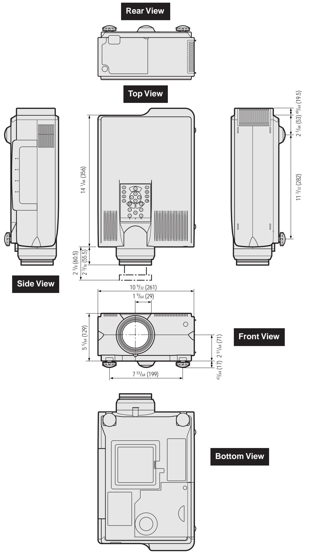

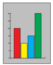
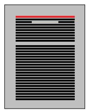

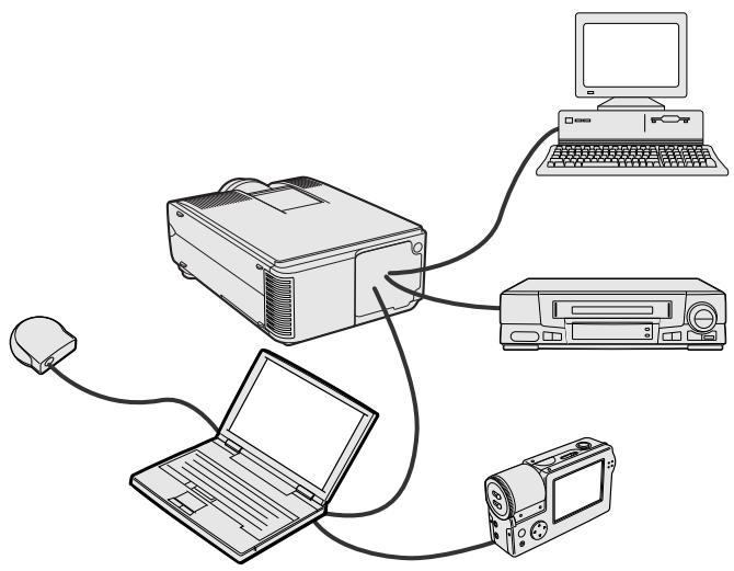

Electronic presentations are one of the most effective tools presenters can use to persuade an audience. There are several ways to enhance your presentation and maximize your effectiveness. The following are guidelines to help you create and deliver a dynamic presentation.
a. Types of Presentations
Computer Presentations
- To present basic information such as graphs, spreadsheets, documents and images, use word processing and spreadsheet applications.
- To convey more complex information and create more dynamic presentations which allow you to control the pace of your delivery, utilize software such as Astound®, Freelance®, Persuasion® or PowerPoint®.
- For high-end multimedia and interactive presentations, use software such as Macromedia Director®.
NOTE
- Astound®, Freelance®, Persuasion®, PowerPoint® and Macromedia Director® are trademarks of their respective companies.
Video Presentations
Use of video equipment, such as a VCR, DVD player and laser disc player, can be effective for delivering instructional or illustrative information that is difficult to present.
Digital Cameras and Personal Digital Assistants (PDAs)
For highly compact and portable presentations, still cameras, digital video cameras, document cameras and PDAs are ideal for transferring data without cumbersome conversions.
Multimedia Presentations
You can integrate all of the above methods for a full multimedia presentation including video, audio, computer applications and World Wide Web information.
Wireless Presentations
Use any IrDA/IrTranP compatible source such as a laptop, digital camera or PDA to project still images quickly and effortlessly without the use of cables.
b. Creative Presentations
Oftentimes presenters do not take advantage of the many subtle ways they can manipulate their electronic slides to more effectively persuade the audience.
Color has a great effect on the audience during a presentation. When used correctly and legibly, studies show that background & foreground colors establish an emotional tone for a presentation, help viewers understand and retain information, and influence an audience to take a desired course of action.
Color Considerations
- Choose legible colors.
Text and graphics colors need sufficient contrast. - Use darker colors for the background since a lighter background can create uncomfortable glare. (Yellow on black creates an ideal contrast.)
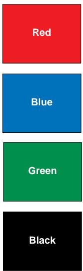

Sans-serif Serif
- Background colors can subconsciously affect the audience:
Red—increases viewers' pulse and breathing and encourages risk taking but can also be associated with financial loss.
Blue—has a calming and conservative affect on the audience but can also create boredom among corporate audiences that are often inundated with this background color.
Green-stimulates interaction.
Black—conveys finality and certainty. Use it as a transitional color between slides when moving from one idea to another.
- Foreground colors create a major impact on how well an audience understands and remembers a message.
- Use one or two bright colors for emphasis.
- Highlight important messages.
- The eye has a difficult time reading certain colored text on certain colored backgrounds. For example, text and background colors in red and green, and blue and black make for difficult viewing.
Colorblind individuals may find it difficult to distinguish between red and green, brown and green, and purple and blue. Avoid using these colors together.
Fonts
- One of the most common mistakes in any type of presentation visual is the selection of type fonts that are too small, too thin, or too difficult to read.
- If you are not sure how well a given font will read on a screen at various sizes, try this: Draw a 6'' × 8'' box on a piece of paper and print out several lines of text inside the box with your computer printer at 300 or 600 dpi resolution. Vary the sizes of text to simulate headline, body and text call-outs for any charts or graphs. Hold the printout at arm's length. This is how your text will look on a 4' (1.2 meters)-wide screen at 10' (3 meters), on a 7.5' (2.3 meters)-wide screen at 20' (6.1 meters) and a 12' (3.7 meters)-wide screen at 30' (9.1 meters). If you cannot read the text easily, you should put less copy on your visuals or use larger typefaces.
- Design your visuals so that they are visible by the viewer in the last row.
- Nothing will ruin your presentation faster than misspell words. Take the time to proofread and edit your work before your visuals become a permanent part of your presentation.
- Mixed case text is easier to read than text which is displayed in capital letters.
- Another important attribute of fonts is whether any particular face is serif or sans-serif. Serifes are small, usually horizontal cross strokes that are added to the end of a letter's main strokes. Because of their ability to coax the eye along the line of type, fonts with serifs are generally acknowledged to be more readable.

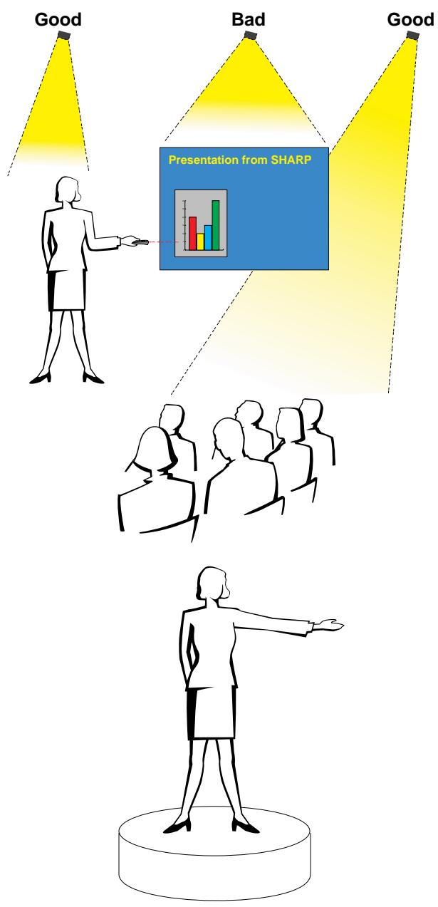
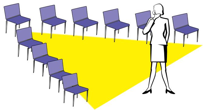
c. Set-Up
When giving a presentation, you need to set the stage both figuratively and literally for success. The way you set up a presentation room will have a great impact on the audience's perception of you and your message. By manipulating the placement and use of the following tools, you will improve the impact of your presentation.
Lighting—Good lighting is an important component of a successful presentation. You should strive to create an unequal distribution of light. An audience should always see as much of the presenter's face as possible, so most of the light should be focused on you. Because it is important for you to be able to read the audience's faces and body language, some light should be shed upon them. However, no light should shine on the screen.
Stage—When presenting on the same level surface that your audience is on, most people can only see the top one-third of your body. Therefore, it is recommended that when giving a presentation to an audience of 25 or more, you stand on a stage or platform. As more of your body is visible, the easier it is to communicate with an audience.
Podiums—The best presenters avoid podiums because they hide 75% of the body and restrict movement. However, many people feel more comfortable with a podium to hold their notes and hide their discomfort. If you must use a podium, angle it at 45 degrees to the audience so that you are not completely hidden.
Visuals—It is imperative that you make sure your visuals are large enough and projected far enough for the audience to see. Eight times the height of an image is the optimal viewing distance to read 24 point type. The bottom of a screen should be at least 6' (1.8 meters) above the floor.
Screen—The screen should always be in the center of the room so that all audience members can see it. Because people read from left to right, you should always stand to the audience's left when discussing visuals.
Seating—Arrange seating according to the dynamics of your presentation. If the presentation is more than half-a-day, use classroom style seating—a chair and a desk. If you would like to encourage audience interaction, use chevron seating, angling the chairs into a "V" shape. When you have a very small audience, a "U" shaped arrangement will increase interchange.

d. Rehearsing & Delivery
- The best time to rehearse is the day or evening before, not a couple of hours before, and the best place to rehearse is in the actual room. Rehearsing a speech in a small office is not the same as standing up in front of 100 people in a hotel ballroom or classroom.
- Due to varying processor speeds of computers, practice your slide transitions for proper timing.
- Whenever possible, set up your equipment well in advance to allow adequate time to resolve any unexpected issues such as lighting, power, seating and audio.
- Thoroughly check every piece of equipment you bring along. Make sure you have fresh batteries in your remote controls and laptop computer. Fully charge your computer's battery before the presentation and connect your AC adaptor for added safety.
- Make sure you are completely familiar with the control panel on your projector and remote controls.
- If you are using a microphone, check it out before hand and walk around to see where you might have problems with feedback. Avoid standing in these problem areas during your presentation.

e. Presentation Tips
- Before beginning, visualize yourself delivering an outstanding presentation.
- Know your speech, memorizing at least the first three minutes of your presentation will allow you to focus on your rhythm and pacing.
- Speak to early arrivals to help you build a rapport with the audience and make you feel more comfortable.
- Do not be overly dependent on your visuals by reciting what your audience is already reading. Know your material well enough to be able to deliver the presentation with ease. Use your visuals to emphasize keypoints.
- Be sure to project your voice clearly and use eye contact to maintain audience attention.
- Do not wait until halfway through your presentation to get your point across. If you wait and try to create a "build-up", you may lose some of your audience along the way.
- Keep your audience's attention. As most people only focus for 15 to 20 minutes during a one-hour presentation, it is important to recapture their attention periodically. Use phrases like, "This is critical to my point" or "This is absolutely fundamental" to remind them you are saying something they need to hear.
Aspect ratio
Width and height ratio of an image. The normal aspect ratio of a computer and video image is 4 : 3 . There are also wide images with an aspect ratio of 16 : 9 and 21 : 9 .
Auto sync
Optimizes projected computer images by automatically adjusting certain characteristics.
Background
Initial setting image projected when no signal is being input.
Clock
Clock adjustment is used to adjust vertical noise when clock level is incorrect.
Compatibility
Ability to use with various image signal modes.
Composite sync
Signal combining horizontal and vertical sync pulses.
Digital keystone correction
Function to digitally correct a distorted image when the projector is set up at an angle.
Dot by dot
Mode that projects images in their native resolution.
Fit to screen
Function to adjust an image without keeping a native aspect ratio other than 4 : 3 , and project it in a 4 : 3 ratio .
Freeze
Function to freeze a moving image.
GUI
Graphical User Interface. User interface with graphics that allow easier operation.
I/P conversion
Function to convert an image between "Interlaced" and "Progressive" scan displays.
Intelligent compression and expansion
High quality resizing of lower and higher resolution images to fit the projector's native resolution.
IrCOM
Function to transmit still images from a computer, hand-held PC or digital still camera via infrared communication for "Wireless Presentations".
IrDA
Standard protocol for wireless communication.
IrTranP
Standard format (protocol) for transmission of images.
Magnification
Digitally zooms in on a portion of an image.
Portable Document Format. Documentation format used to transfer text and images from the CD-ROM.
Phase
Phase shift is a timing shift between isomorphic signals with the same resolution. When phase level is incorrect, the projected image typically displays horizontal flicker.
Presentation tools
Helpful tools used to emphasize keypoints throughout a presentation.
RS-232C
Function to control the projector from the computer by using the RS-232C ports on the projector and computer.
Startup image
The image displayed when the projector is turned on.
Status function
Displays the settings of each adjustment item.
Sync
Synchronizes the resolution and phase shift of two signals. When receiving an image with a resolution different from that of the computer, the projected image may be distorted.
Sync on green
Video signal mode of a computer which overlaps horizontal and vertical sync signal to green color signal pin.
Wireless mouse
Function to operate the mouse control of the computer with the supplied remote control.
XGA resolution
The resolution with 1,024 × 768 pixels that uses the signal of an IBM/AT compatible (DOS/V) computer.

A
AC socket 11
ADJUSTMENT buttons 23
Air filter 46
Aspect ratio 36
Audio adjustments 28
AUDIO INPUT 1 terminal 11
AUDIO INPUT 2 terminal 11
AUDIO INPUT terminals 13
AUDIO OUTPUT terminal 14
Automatic power shutoff function 38
Auto sync adjustment 30
AUTO SYNC button 29
B
Background 41
BACKLIGHT button 22
BLACK SCREEN button 37
BNC-RCA adaptors 13
C
Carrying handle 50
Ceiling-mount 20
Ceiling ^+ Rear 42
Clock 29
Computer audio cable 11
Computer cable 11
Cooling fan (Exhaust vent) 5
Cooling fan (Intake vent) 7
D
Digital keystone correction 3
DIN-D-sub RS-232C cable 14
Dot by dot 36
E
ENLARGE button 34
ENTER button 23
Extra air filter 10
F
15 pin/BNC switch 11
Fit to screen 36
Foot releases 19
FREEZE button 33
G
GAMMA button 35
GUI (Graphical User Interface) 23
1
INPUT 1 port 11
INPUT 1 terminals 12
INPUT 2 port 11
INPUT button 17
Intelligent compression and expansion 3
I/P conversion 39
IrCOM 25
IrCOM button 25
IrCOM sensors 25
IrDA 59
IrTranP 59
K
Kensington Security Standard connector 49
L
LAMP REPLACEMENT indicator 47
LASER POINTER button 22
Laser pointer window 5
LEFT-CLICK button 22
LENS button 19
Lens cap 50
M
MENUButton 23
MOUSE/ADJUSTMENT switch 21
MOUsE buttons 22
Mouse control cable for IBM PS/2 15
Mouse control cable for Mac 15
Mouse control serial cable 15
MUTE button 17
0
On-screen display language 26
OUTPUT port 7
P
PDF 6
Phase 29
Picture adjustments 27
POWER buttons 17
Power cord 11
POWERindicator 16
Presentation tools 43
R
Rear projection 20
Remote control 21
Remote control sensor 21
Remote control signal transmitter 8
Remote mouse receiver 21
RESIZE button 36
RIGHT-CLICK button 22
RS-232C port 14
s
Sharp Advanced Presentation Software (SAPS) 25
Speakers 7
Startup image 41
Status function 44
S-VIDEO INPUT terminal 13
Sync 30
Sync on green 51
T
TEMPERATURE WARNING indicator 47
TOOLS button 43
U
UNDO button 19
V
VIDEO INPUT terminal 13
VOLUME buttons 17
W
Wired remote control input 22
WIRED REMOTE control input terminal 22
Wireless mouse 21
X
XGA resolution 3
SHARP CORPORATION
OSAKA, JAPAN