AS01346FP - Television Allsee - Free user manual and instructions
Find the device manual for free AS01346FP Allsee in PDF.

User questions about AS01346FP Allsee
0 question about this device. Answer the ones you know or ask your own.
Ask a new question about this device
Download the instructions for your Television in PDF format for free! Find your manual AS01346FP - Allsee and take your electronic device back in hand. On this page are published all the documents necessary for the use of your device. AS01346FP by Allsee.
USER MANUAL AS01346FP Allsee
text_image
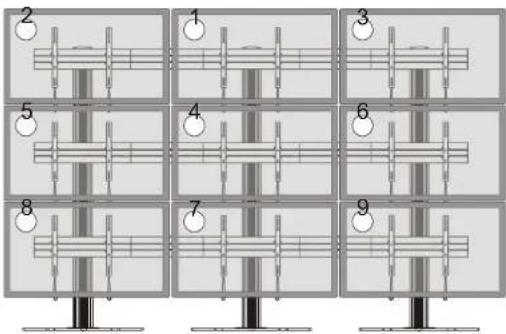
Diagram showing nine numbered musical instrument positions arranged in a grid, likely for playing or recording purposes.Note: The displays are installed by the numerical order given.
text_image
Diagram showing nine labeled mechanical or structural components arranged in a grid, with numbered annotations indicating positions.Note: The angle of displays are adjusted by the numerical order given.
Maintenance
- Check that the bracket is secure and safe to use at regular intervals (at least every three months)
- Please contact your distributor if you have any questions.
INSTALLATION MANUAL
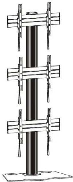
Video Wall Stand and Accessories
natural_image
Technical line drawing of a vertical structural component with multiple horizontal supports (no text or symbols)Optional Accessories

text_image
AS01K Note: The accessories are not standard equipped. The accessories will be selected according to user requirement.
CAUTION: DO NOT EXCEED RATED LISTED WEIGHT, SERIOUS INJURY OR PROPERTY DAMAGE MAY OCCUR!
AS01346FP

300x300/400x200 400x400/600x400


ISSUED: OCT. 2014
NOTE: Read the entire instruction manual before you start installation and assembly.

WARNING
- Do not begin the installation until you have read and understood all the instructions and warnings contained in this installation sheet. If you have any questions regarding any of the instructions or warnings, please contact your local distributor.
- This mounting bracket was designed to be installed and utilised ONLY as specified in this manual. Improper installation of this product may cause damage or serious injury.
- Always use an assistant or mechanical lifting equipment to safely lift and position the equipment.
- Tighten screws firmly, but do not over tighten. Over tightening can cause damage to the items, This greatly reduces their holding power.
- This product is intended for indoor use only. Using this product outdoors could lead to product failure and personal injury.
IMPORTANT: Ensure that you have received all parts according to the component checklist prior to installation. If any parts are missing or faulty, telephone your local distributor for a replacement.
AS01346FP


text_image
column (x1) E rubber pad (x4) F connecting plate (x1) G top cover (x1) H iron expansion bolt (x6) I cable clamp (x12) J M8x16 (x4) K M8x16 (x6) L M8x40(x4) M 3mm Allen key (x1) N 4mm Allen key (x1) O 5mm Allen key (x1) P 6mm Allen key (x1) QPackage M (x3)


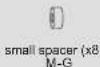

AS01K (The following accessories are optional)
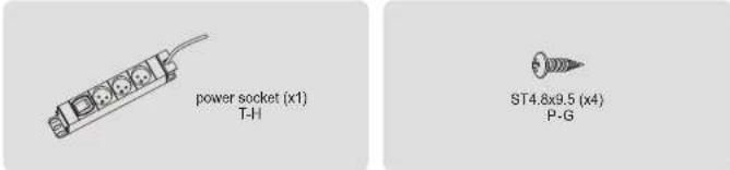
text_image
power socket (x1) T-H ST4.8x9.5 (x4) P-G- Installing the Rubber Pads
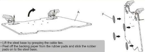
text_image
• Lift the steel base by grasping the cable ties. • Peel off the backing paper from the rubber pads and stick the rubber pads on to the steel base.- For the model AS01K installation
(Assembly based on the accessories selected by user.)
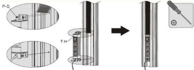
text_image
P-G T-HAttach the power socket to the back of column using the appropriate screws. Tighten all screws with a phillips screwdriver.
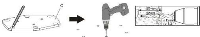
3a. For Concrete Floor Mounting
text_image
Technical diagram showing a mechanical assembly with labeled components and a 3D profile view of a drill bit with dimensional annotations.Mark the exact location of mounting holes and pre-drill these mounting holes with a 12mm drilling bit to at least 62mm in depth. Remove the dust in the holes.

text_image
Diagram showing a mechanical component with labeled parts and an arrow indicating transformation or assembly.First tighten the iron expansion bolts with an Allen key, and then loosen the iron expansion bolts in order to separate the bolts and the expansion tubes.
text_image
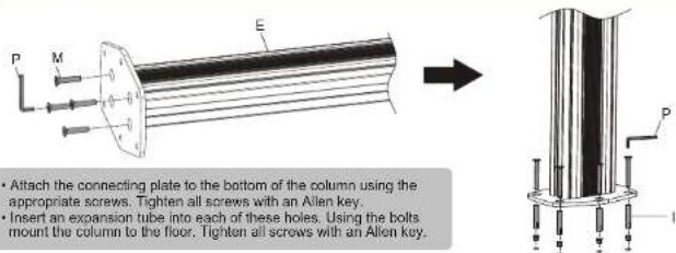
P M E Attach the connecting plate to the bottom of the column using the appropriate screws. Tighten all screws with an Allen key. Insert an expansion tube into each of these holes. Using the bolts mount the column to the floor. Tighten all screws with an Allen key.3b. For the Floor Stand Mounting

text_image
Remove the cable ties.Attach the column to the steel base using the appropriate screws. Tighten all screws with an Allen key.
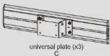
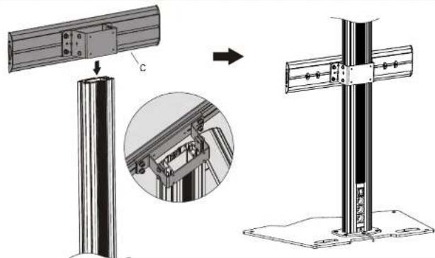
- Installing the Universal Plates
natural_image
Technical illustration of a metal frame assembly with a cylindrical base and a cross-shaped structure, showing structural details (no text or symbols)Insert the universal plates to the column along the column rails respectively. NOTE: With the arrow pointing upward.
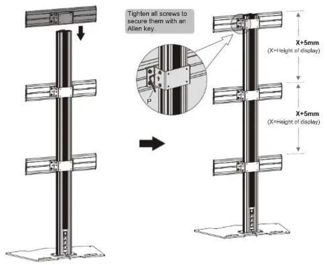
text_image
Tighten all screws to secure them with an Allen key. X+5mm (X=Height of display) X+5mm (X=Height of display)- Installing the Top Cover
text_image
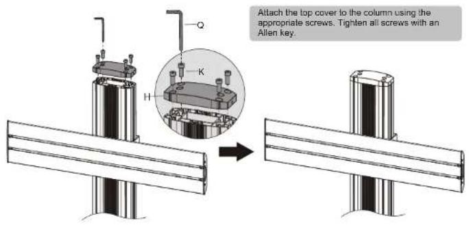
Attach the top cover to the column using the appropriate screws. Tighten all screws with an Allen key.5
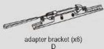
- Installing the Adapter Brackets
text_image
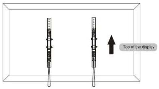
Top of the display6-1 For Flat Back Screens

text_image
Technical diagram showing assembly of two mechanical components with labeled parts and a magnified view of the assembly.6
6-2 For Recessed Back Screens or to Access A/V Inputs

text_image
Technical diagram showing mechanical assembly with labeled components and corresponding schematic diagrams of motor configurations.Note: Choose the appropriate screws, washers and spacers (if necessary) according to the type of screens.
- Position the adapter brackets as close as possible to the center of the displays.
- Screw the adapter brackets onto the displays.
Tighten all screws but do not over tighten.
- Hanging the Displays onto the Universal Plates
text_image
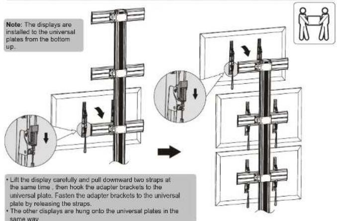
Note: The displays are installed to the universal plates from the bottom up. • Lift the display carefully and pull downward two straps at the same time, then hook the adapter brackets to the universal plate. Fasten the adapter brackets to the universal plate by releasing the straps. • The other displays are hung onto the universal plates in the same way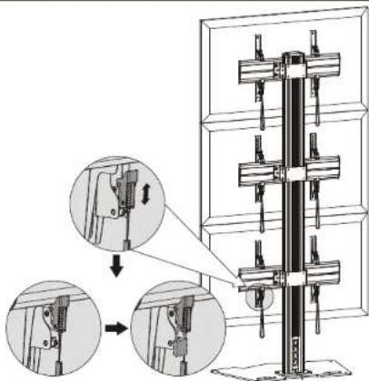
text_image
Technical diagram showing mechanical assembly steps with magnified views of componentsUse the padlocks to prevent the displays from being stolen (The padlocks are not included).
- Micro-Adjustment
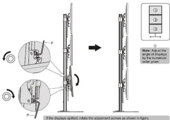
text_image
If the displays uplifted, rotate the adjustment screws as shown in figure. Note: Adjust the angle of displays by the numerical order given.
text_image
Technical diagram illustrating mechanical assembly with labeled components and directional arrows indicating motion or assembly.If the displays tilted down, rotate the adjustment screws as shown in figure.

text_image
up down Note: Leave a one millimeter gap between the displays.Rotate the adjustment screws as shown in figure to make a one millimeter gap left between the displays.
- Cable Management
natural_image
Mechanical assembly diagram showing two stages of a mechanical clamp or bracket assembly, with magnified views highlighting internal components (no text or symbols present)Insert the cable clamps horizontally into the plate slots, then turn the cable clamps to the vertical to secure them.

natural_image
Technical line drawing of a three-tier mechanical assembly with vertical supports and mounting brackets (no text or symbols)Run the cables through the cable clamps and the rubber strip.
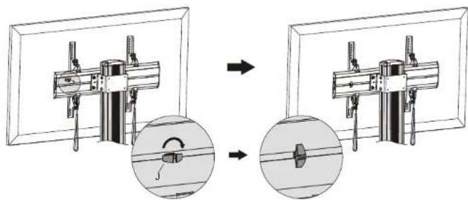
10. Adjustment

text_image
+3° -3°11. Multi-screen Combination Solution
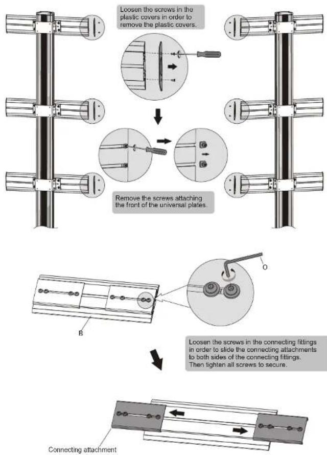
flowchart
graph TD
    A["Loosen the screws in the plastic covers in order to remove the plastic covers."] --> B["Remove the screws attaching the front of the universal plates."]
    B --> C["Connecting attachment"]
    C --> D["Leosen the screws in the connecting fittings in order to slide the connecting attachments to both sides of the connecting fittings. Then tighten all screws to secure."]
text_image
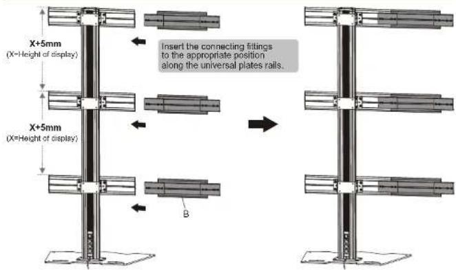
X+5mm (X=Height of display) Insert the connecting fittings to the appropriate position along the universal plates rails. X+5mm (X=Height of display) B
text_image
Note: Make sure that the universal plates are at the same level with each other. X+5mm (X=Height of display) X+5mm (X=Height of display) Use the connecting fittings to assemble the other stand. Note: Make sure that the stands are in alignment. Note: The position which the connecting fittings insert to the universal plate is determined by the size of displays. Smaller display Larger display or O Use the connecting fittings to assemble the other stand.Tighten all screws to secure them.
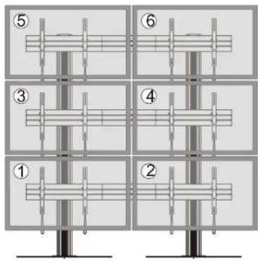
text_image
Diagram showing six labeled mechanical or structural assembly steps, numbered 1 to 6, with vertical supports and internal components.Note: The displays are installed by the numerical order given.

text_image
1mm Note: Leave a one millimeter gap between the displays. ① ② ③ ④ ⑤ ⑥ 1mmNote: The angle of displays are adjusted by the numerical order given.