GCV05 - Vacuum Cleaner MAKITA - Free user manual and instructions
Find the device manual for free GCV05 MAKITA in PDF.

User questions about GCV05 MAKITA
0 question about this device. Answer the ones you know or ask your own.
Ask a new question about this device
Download the instructions for your Vacuum Cleaner in PDF format for free! Find your manual GCV05 - MAKITA and take your electronic device back in hand. On this page are published all the documents necessary for the use of your device. GCV05 by MAKITA.
USER MANUAL GCV05 MAKITA
natural_image
Line drawing of a portable air purifier device with attached cable and control panel (no text or symbols)SPECIFICATIONS
| Model: GCV05 | ||
| Capacity Filter bag 2.0 L (0.53 gal.) | ||
| Maximum air volume(With hose ø32 mm (1-1/4") x 1.0 m (3-15/16")) | 2.4 m^3/min (84.8 cu.ft/min) | |
| Vacuum 18 kPa | ||
| Dimensions (L x W x H)(excluding the harness, with BL4040) | 233 mm x 150 mm x 375 mm(9-1/8" x 5-7/8" x 14-3/4") | |
| Rated voltage D.C. 36 V - 40 V max | ||
| Net weight 4.1 - 5.3 kg (9.0 - 11.7 lbs) | ||
• Due to our continuing program of research and development, the specifications herein are subject to change without notice.
- Specifications may differ from country to country.
- The weight does not include accessories but battery cartridge(s). The lightest and heaviest combination weight of the appliance and battery cartridge(s) are shown in the table.
- The length of supplied hose varies depending on the countries.
Applicable battery cartridge and charger
| Battery cartridge BL4020 / BL4025 / BL4040 / BL4050F / BL4080F | |
| Charger DC40RA / DC40RB / DC40RC |
• Some of the battery cartridges and chargers listed above may not be available depending on your region of residence.
WARNING: Only use the battery cartridges and chargers listed above. Use of any other battery cartridges and chargers may cause injury and/or fire.
WARNING: Do not use a corded power supply such as battery adapter or portable power pack with this appliance. The cable of such power supply may hinder the operation and result in personal injury.
SAFETY WARNINGS
IMPORTANT SAFETY INSTRUCTIONS
When using an electrical appliance, basic precautions should always be followed, including the following:
READ ALL INSTRUCTIONS BEFORE USING THIS APPLIANCE.
WARNING
To reduce the risk of fire, electric shock or injury:
- Do not leave appliance when battery fitted. Remove battery from appliance when not in use and before servicing.
- Do not use on wet surfaces. Do not expose to rain. Store indoors.
- Do not allow to be used as a toy. Close attention is necessary when used by or near children.
- Use only as described in this manual. Use only manufacturer's recommended attachments.
-
Do not use with damaged battery. If appliance is not working as it should, has been dropped, damaged, left outdoors, or dropped into water, return it to a service center.
-
Do not handle appliance with wet hands.
- Do not put any object into openings. Do not use with any opening blocked; keep free of dust, lint, hair, and anything that may reduce air flow.
- Keep hair, loose clothing, fingers, and all parts of body away from openings and moving parts.
- Turn off all controls before removing the battery cartridge.
- Use extra care when cleaning on stairs.
- Do not use to pick up flammable or combustible liquids, such as gasoline, or use in areas where they may be present.
- Do not pick up anything that is burning or smoking, such as cigarettes, matches, or hot ashes.
- Do not use without dust collecting bag in place.
- Do not charge the battery outdoors.
- Prevent unintentional starting. Ensure the switch is in the off-position before connecting to battery pack, picking up or carrying the appliance. Carrying the appliance with your finger on the switch or energizing appliance that have the switch on invites accidents.
- Disconnect the battery pack from the appliance before making any adjustments, changing accessories, or storing appliance. Such preventive safety measures reduce the risk of starting the appliance accidentally.
- Recharge only with the charger specified by the manufacturer. A charger that is suitable for one type of battery pack may create a risk of fire when used with another battery pack.
- Use appliances only with specifically designated battery packs. Use of any other battery packs may create a risk of injury and fire.
- When battery pack is not in use, keep it away from other metal objects, like paper clips, coins, keys, nails, screws or other small
metal objects, that can make a connection from one terminal to another. Shorting the battery terminals together may cause burns or a fire.
- Under abusive conditions, liquid may be ejected from the battery; avoid contact. If contact accidentally occurs, flush with water. If liquid contacts eyes, additionally seek medical help. Liquid ejected from the battery may cause irritation or burns.
- Do not use a battery pack or appliance that is damaged or modified. Damaged or modified batteries may exhibit unpredictable behaviour resulting in fire, explosion or risk of injury.
- Do not expose a battery pack or appliance to fire or excessive temperature. Exposure to fire or temperature above 130 °C may cause explosion.
- Follow all charging instructions and do not charge the battery pack or appliance outside of the temperature range specified in the instructions. Charging improperly or at temperatures outside of the specified range may damage the battery and increase the risk of fire.
- Have servicing performed by a qualified repair person using only identical replacement parts. This will ensure that the safety of the product is maintained.
- Do not modify or attempt to repair the appliance or the battery pack except as indicated in the instructions for use and care.
- Do not use a corded power supply such as battery adapter or portable power pack with this machine. The cable of such power supply may hinder the operation and result in personal injury.
SAVE THESE
INSTRUCTIONS.
This appliance is intended for commercial use.
ADDITIONAL SAFETY RULES
- Read this instruction manual and the charger instruction manual carefully before use.
-
Do not vacuum the following:
-
Flammable liquid (kerosene, gasoline, solvents such as benzine, thinner, etc.)
- Hot substances that are burning or smoking (cigarettes, matches, incense sticks, candles, hot ashes), sparks and metal dust generated by cutting or grinding metal, etc.
- Flammable material (toner, paint, spray, etc.)
• Foam like carpet cleaning agent, etc. (they may cause explosion or fire)
• Explosive or pyrophoric substances (nitroglycerin, aluminum, magnesium, titanium, zinc, red phosphorus, yellow phosphorus, celluloid, etc. and their dust, gas or steam) - Sharp objects (glass, cutlery, wood splinter, metal, stone, nail, razor, push pin, etc.)
• Solidifying and conductive fine powder (metal or carbon powder) - Dehumidifier
• Large amount of powder (flour, fire extinguisher powder, etc.) - Substances that cause toxic symptoms
- Aggressive chemicals (acid, leach, etc.)
- Liquid or damp garbage, including vomit and excreta
- Asbestos
- Pesticides
Such action may cause fire, injury and/or property damage.
To reduce your exposure to these chemicals, always wear approved respiratory protection such as dust masks that are specially designed to filter out microscopic particles. Direct the exhaust air away from your face and body.
NOTE: Read the OSHA regulation on silica dust to understand the requirements needed to reduce exposure to silica dust at the job-site. Specific rules apply to the drilling, demolition cutting and grinding materials that contain silica. All OSHA requirements regarding reducing silica dust can be found at the OSHA website: www.osha.gov.
- Stop operation immediately if you notice anything abnormal.
- If you drop or strike the cleaner, check it carefully for cracks or damage before operation.
- Do not bring close to stoves or other heat sources.
- Do not block the intake hole or vent holes.
Symbols
The followings show the symbols used for tool.
| v | volts |
| - | direct current |
Important safety instructions for battery cartridge
- Before using battery cartridge, read all instructions and cautionary markings on (1) battery charger, (2) battery, and (3) product using battery.
- Do not disassemble or tamper with the battery cartridge. It may result in a fire, excessive heat, or explosion.
- If operating time has become excessively shorter, stop operating immediately. It may result in a risk of overheating, possible burns and even an explosion.
-
If electrolyte gets into your eyes, rinse them out with clear water and seek medical attention right away. It may result in loss of your eyesight.
-
Do not short the battery cartridge:
(1) Do not touch the terminals with any conductive material.
(2) Avoid storing battery cartridge in a container with other metal objects such as nails, coins, etc.
(3) Do not expose battery cartridge to water or rain.
A battery short can cause a large current flow, overheating, possible burns and even a breakdown.
- Do not store and use the tool and battery cartridge in locations where the temperature may reach or exceed 50 °C (122 °F).
- Do not incinerate the battery cartridge even if it is severely damaged or is completely worn out. The battery cartridge can explode in a fire.
- Do not nail, cut, crush, throw, drop the battery cartridge, or hit against a hard object to the battery cartridge. Such conduct may result in a fire, excessive heat, or explosion.
- Do not use a damaged battery.
- The contained lithium-ion batteries are subject to the Dangerous Goods Legislation requirements.
For commercial transports e.g. by third parties, forwarding agents, special requirement on packaging and labeling must be observed.
For preparation of the item being shipped, consulting an expert for hazardous material is required.
Please also observe possibly more detailed national regulations.
Tape or mask off open contacts and pack up the battery in such a manner that it cannot move around in the packaging.
- When disposing the battery cartridge, remove it from the tool and dispose of it in a safe place. Follow your local regulations relating to disposal of battery.
-
Use the batteries only with the products specified by Makita. Installing the batteries to non-compliant products may result in a fire, excessive heat, explosion, or leak of electrolyte.
-
If the tool is not used for a long period of time, the battery must be removed from the tool.
- During and after use, the battery cartridge may take on heat which can cause burns or low temperature burns. Pay attention to the handling of hot battery cartridges.
- Do not touch the terminal of the tool immediately after use as it may get hot enough to cause burns.
- Do not allow chips, dust, or soil stuck into the terminals, holes, and grooves of the battery cartridge. It may result in poor performance or breakdown of the tool or battery cartridge.
- Unless the tool supports the use near high-voltage electrical power lines, do not use the battery cartridge near a high-voltage electrical power lines. It may result in a malfunction or breakdown of the tool or battery cartridge.
- Keep the battery away from children.
SAVE THESE INSTRUCTIONS.
CAUTION: Only use genuine Makita batteries. Use of non-genuine Makita batteries, or batteries that have been altered, may result in the battery bursting causing fires, personal injury and damage. It will also void the Makita warranty for the Makita tool and charger.
Tips for maintaining maximum battery life
- Charge the battery cartridge before completely discharged. Always stop tool operation and charge the battery cartridge when you notice less tool power.
- Never recharge a fully charged battery cartridge. Overcharging shortens the battery service life.
- Charge the battery cartridge with room temperature at 10 °C - 40 °C ( 50 °F - 104 °F ). Let a hot battery cartridge cool down before charging it.
- When not using the battery cartridge, remove it from the tool or the charger.
- Charge the battery cartridge if you do not use it for a long period (more than six months).
FUNCTIONAL DESCRIPTION
⚠️CAUTION: Always be sure that the appliance is switched off and the battery cartridge is removed before adjusting or checking function on the appliance.
Installing or removing battery cartridge
⚠️CAUTION: Always switch off the tool before installing or removing of the battery cartridge.
⚠️CAUTION: Hold the tool and the battery cartridge firmly when installing or removing battery cartridge. Failure to hold the tool and the battery cartridge firmly may cause them to slip off your hands and result in damage to the tool and battery cartridge and a personal injury.
text_image
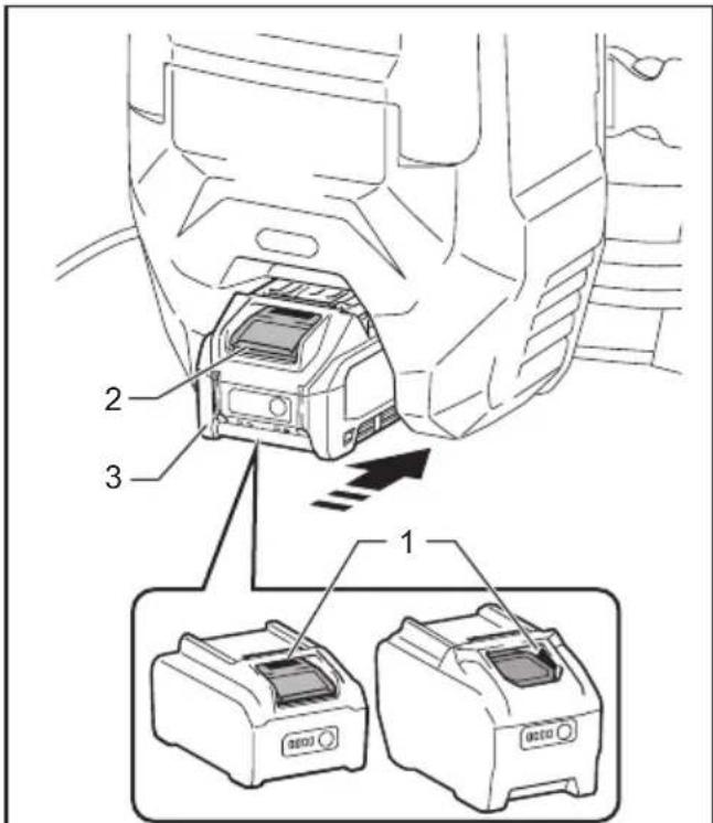
Diagram showing a device with labeled parts and two separate devices, likely illustrating a mechanical or electronic assembly.Fig.1
▶ 1. Red indicator 2. Button 3. Battery cartridge
To remove the battery cartridge, slide it from the tool while sliding the button on the front of the cartridge.
To install the battery cartridge, align the tongue on the battery cartridge with the groove in the housing and slip it into place. Insert it all the way until it locks in place with a little click. If you can see the red indicator as shown in the figure, it is not locked completely.
CAUTION: Always install the battery cartridge fully until the red indicator cannot be seen. If not, it may accidentally fall out of the tool, causing injury to you or someone around you.
CAUTION: Do not install the battery cartridge forcibly. If the cartridge does not slide in easily, it is not being inserted correctly.
Indicating the remaining battery capacity
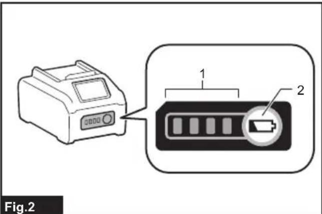
Press the check button on the battery cartridge to indicate the remaining battery capacity. The indicator lamps light up for a few seconds.
text_image
Fig.2▶ 1. Indicator lamps 2. Check button
| Indicator lamps Remaining | capacity | ||
| Lighted Off | Blinking | ||
| 75% to 100% | |||
| 50% to 75% | |||
| 25% to 50% | |||
| 0% to 25% | |||
| Charge the battery. | |||
| The battery may have malfunctioned. | |||
NOTE: Depending on the conditions of use and the ambient temperature, the indication may differ slightly from the actual capacity.
NOTE: The first (far left) indicator lamp will blink when the battery protection system works.
Indicating the remaining battery capacity

text_image
1 2 MOSSO▶ 1. Battery indicator 2. ⏻ button
Fig.3
Press the ⏻ button to indicate the remaining battery capacities.
| Battery indicator status Remaining | battery capacity | ||
| On | [HH8E]Off | [5020K]Blinking | |
 | 50% to 100% | ||
 | 20% to 50% | ||
 | 0% to 20% | ||
 | Charge the battery | ||
Off
Blinking
Appliance / battery protection system
The appliance is equipped with appliance / battery protection system. This system automatically cuts off power to the motor to extend appliance and battery life. In this situation, the battery indicator lights up as following table.
| Battery indicator status Status | |||
| On | Off | Blinking | |
| [H22Y] | Overload protection (battery) / Overheat protection (battery) / Overdischarge protection | ||
 | Overheat protection (appliance) | ||
The appliance and the LED light will automatically stop during operation if the appliance or battery is placed under one of the following conditions:
Overload protection
When the appliance / battery is operated in a manner that causes it to draw an abnormally high current, the appliance automatically stops. In this situation, turn the appliance off and stop the application that caused the appliance to become overloaded. Then turn the appliance on to restart.
Overheat protection
When the appliance / battery is overheated, the appliance stops automatically. In this situation, let the appliance / battery cool down before turning the appliance on again.
Overdischarge protection
When the battery capacity becomes low, the appliance stops automatically. If the product does not operate even when the switches are operated, remove the batteries from the appliance and charge the batteries.
Protections against other causes
Protection system is also designed for other causes that could damage the appliance and allows the appliance to stop automatically. Take all the following steps to clear the causes, when the appliance has been brought to a temporary halt or stop in operation.
- Turn the appliance off, and then turn it on again to restart.
- Charge the battery(ies) or replace it/them with recharged battery(ies).
- Let the appliance and battery(ies) cool down.
If no improvement can be found by restoring protection system, then contact your local Makita Service Center.
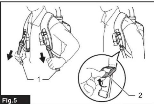
Adjusting belts
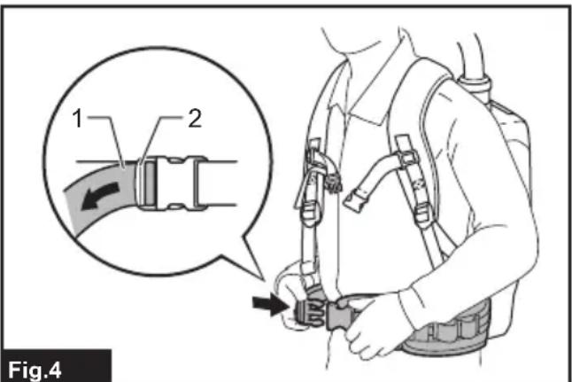
The tightness of the shoulder belts, upper and lower belts can be adjusted. Put your arms through the shoulder belts first then fasten the lower and upper belts. To tighten, pull the end of the strap as illustrated. To loosen, pull up the end of the fastener.
Lower belt
text_image
1 2 Fig.4▶ 1. Strap 2. Fastener
Shoulder belts

text_image
Fig.5 1 2▶ 1. Strap 2. Fastener
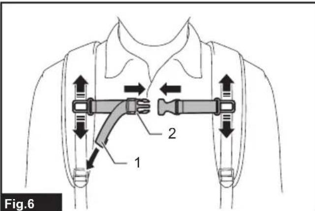
Upper belt

text_image
Fig.6 1 2▶ 1. Strap 2. Fastener
Carrying hook
⚠️CAUTION: Use the hanging/mounting parts for their intended purposes only. Using for unintended purpose may cause accident or personal injury.
Always grab the carrying hook when handling the vacuum cleaner body.

natural_image
Technical line drawing of a mechanical component with labeled parts (no text or symbols beyond label)▶ 1. Carrying hook
Switch action
text_image
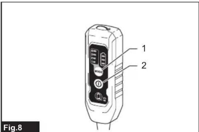
1 2 Fig.8▶ 1. Suction power change button 2. ON/OFF button
To start the cleaner, simply push the ON/OFF button. To switch off, push the ON/OFF button again.
You can change the suction power of the cleaner in four steps by pushing the suction power change button. Each push on this button repeats the 1 to 4 mode in a cycle.
| Level Indication Mode | ||
| 1 |  | Quiet mode |
| 2 |  | Normal speed mode |
| 3 |  | High speed mode |
| 4 |  | Max speed mode |
NOTE: You can change the suction power before turning on the cleaner.
NOTE: The cleaner starts the operation with the same suction power as the last operation.
NOTE: If you remove the battery immediately after turning off the appliance, while the motor is rotating, the cleaner may not start the operation with the same suction power as the last operation.
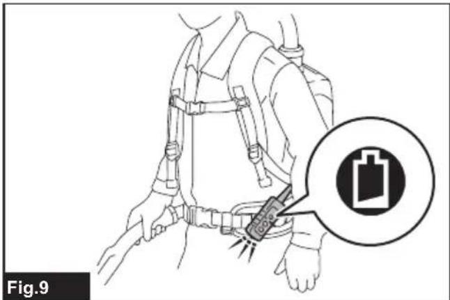
LED light
LED light is installed in the head of the switch box to ease the operations in dark places. Press and hold button to turn the light on. To turn off, press and hold button again.
text_image
Fig.9CAUTION: Do not look in the light or see the source of light directly. Never aim the light to other people's eyes.
NOTE: The LED light is automatically turned off when the vacuum cleaner is not operated for more than 10 minutes.
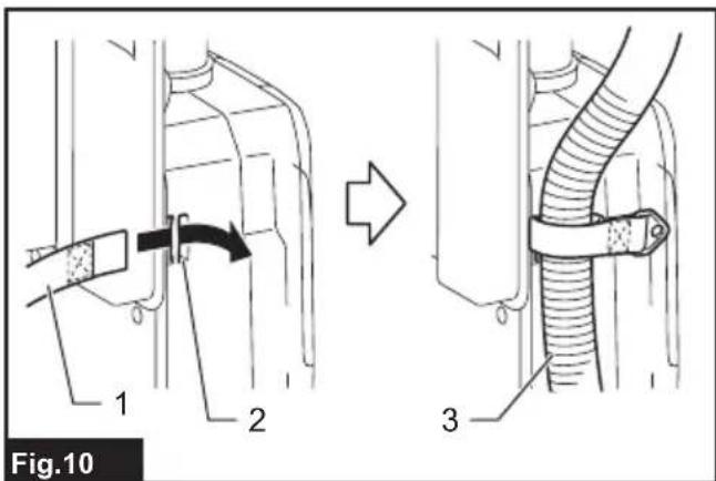
Hose band
Hose band can be used for holding the hose or free nozzle.
To secure the hose to the vacuum cleaner body, pass the hose band through the slot on the body. You can attach the hose band on either side.
text_image
Fig.10 1 2 3▶ 1. Hose band 2. Slot 3. Hose
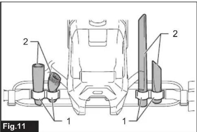
The loop on the lower belt can be used for carrying nozzles as illustrated.
text_image
2 2 1 1 Fig.11▶ 1. Loop 2. Nozzles
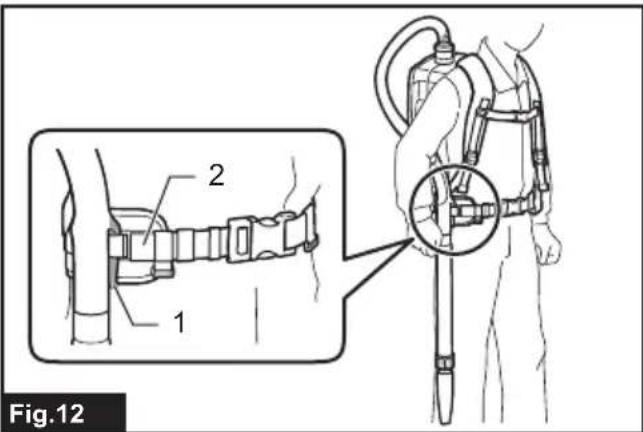
Hose hook
When you suspend the operation, the hook on the bent pipe assembly can be used for hanging the wand on the lower belt.
text_image
Fig.12▶ 1. Hook 2. Lower belt
ASSEMBLY
⚠️CAUTION: Always be sure that the appliance is switched off and the battery cartridge is removed before carrying out any work on the appliance.
Assembling hose
Insert the hose cuff into the vacuum cleaner body and turn it clockwise.

text_image
Fig.13▶ 1. Hose cuff 2. Vacuum cleaner body
Using as a cleaner
Attaching bent pipe assembly
Optional accessory
NOTE: You don't need to perform this procedure if your model comes with the bent pipe assembly attached to the hose.
NOTE: There are two types of bent pipe assembly; the one for slide-type extension wand and the one for ring-type extension wand. If you prepare the bent pipe assembly, choose the one for your desired extension wand type.
The bent pipe assembly is used for connecting the extension wand or nozzle for vacuum cleaning to this product.
If you want to use this product as the vacuum cleaner, attach the bent pipe assembly to the hose.
To attach, unscrew the front cuff from the hose and fasten the sleeve of bent pipe assembly onto the hose. To remove, loosen the sleeve of bent pipe assembly from the hose.
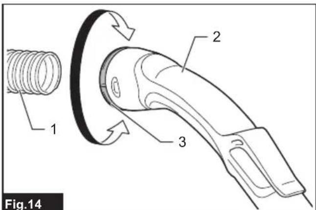
text_image
Fig.14▶ 1. Hose 2. Bent pipe assembly 3. Sleeve
Assembling nozzle and wand
Optional accessory
NOTE: The type of the nozzle and wand included in the product varies depending on countries. In some countries, the nozzle and wand are not included.
- Twist and insert the nozzle to the extension wand.

text_image
Fig.15▶ 1. Extension wand 2. Free nozzle 3. T-shape nozzle 4. T-shape nozzle (slim)
NOTE: By twisting the nozzle while inserting, the nozzle can be attached to the extension wand securely.
NOTE: For the model with 38 mm hose and front cuff 38, attach the supplied nozzle to the aluminum bending pipe / aluminum straight pipe.
- Follow the procedures below, depending on the type of the extension wand :
NOTE: The slide-type extension wand and the ring-type extension wand are not compatible with each other. If you want to change the slide-type extension wand to the ring-type extension wand or vice versa, change the bent pipe assembly also.
For the slide-type extension wand
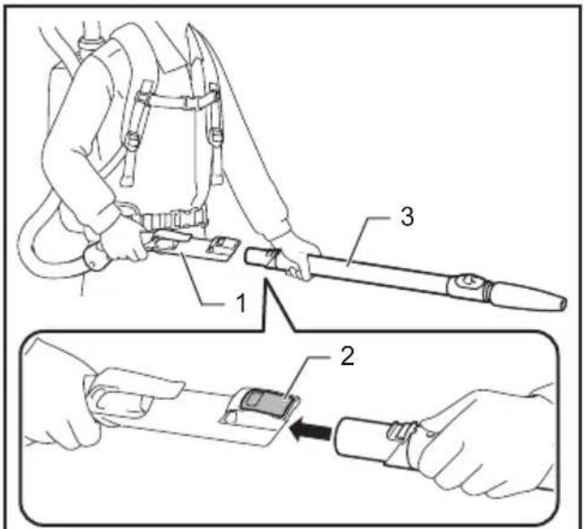
Shoulder the vacuum cleaner body then insert the extension wand into the bent pipe assembly until it clicks. To disconnect, extract the extension wand with pressing the button.
text_image
Technical diagram showing a hand holding a tool with labeled parts, including a 3D view and a close-up of the component being inserted.Fig.16
▶ 1. Bent pipe assembly 2. Button 3. Slide-type extension wand
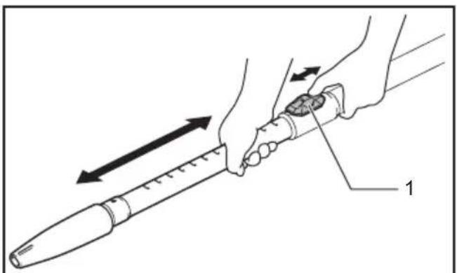
The length of the wand can be adjusted. With pressing the slide button, adjust the wand length. The length is locked when releasing the slide button.
natural_image
Illustration of a hand holding a pen-like tool with directional arrows indicating movement or force (no text or symbols present)Fig.17
▶ 1. Slide button
For the ring-type extension wand
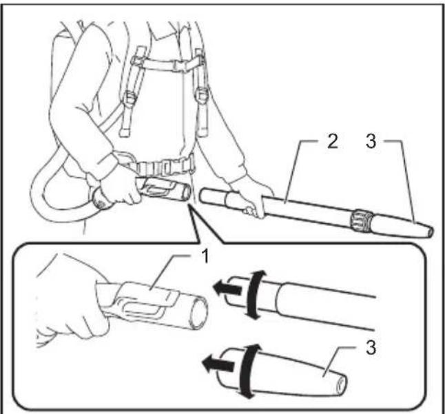
Shoulder the vacuum cleaner body then twist and insert the extension wand into the bent pipe assembly. To disconnect, twist and extract it.
text_image
Technical diagram showing a person using a tool to adjust or install a cylindrical device, with labeled parts 1, 2, and 3.Fig.18
▶ 1. Bent pipe assembly 2. Ring-type extension wand 3. Free nozzle
NOTE: The free nozzle can be attached to the bent pipe assembly without pipe lock directly.
The length of the wand can be adjusted. Loosen the ring on the wand and adjust the wand length. Tighten the ring at your desired length.

text_image
Fig.19 1▶ 1. Ring
For the aluminum bending pipe / aluminum straight pipe
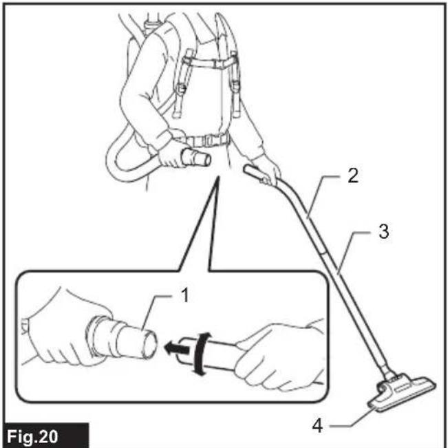
(Only for the model with 38 mm hose and front cuff 38) Shoulder the vacuum cleaner body then twist and insert the pipe into the front cuff. To disconnect, twist and extract it.
text_image
Fig.20 1 2 3 4▶ 1. Front cuff 38 2. Aluminum bending pipe
- Aluminum straight pipe 4. Nozzle
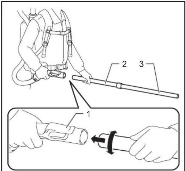
For the two aluminum straight pipes
Shoulder the vacuum cleaner body then twist and insert the pipes. To disconnect, twist and extract it.
text_image
Technical diagram showing a mechanical assembly with labeled parts, including a tool and a close-up of a cylindrical component.Fig.21
▶ 1. Bent pipe assembly 2. Aluminum straight pipe 1
- Aluminum straight pipe 2
Connecting the tool
NOTE: If the bent pipe assembly is attached to the hose, remove it beforehand.
To connect a tool to the cleaner, the dedicated hose and/or additional parts are required. Depending on your cleaner model, you need to replace the hose and/or prepare additional parts.
Refer to the following table for details.
| Supplied hose diameter | Hose end type A | Action |
| ø28 mm |  without part without part | Attach the front cuff. |
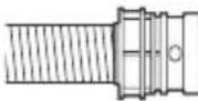 with snap-on part with snap-on part | Replace the hose end (snap-on part) with the front cuff.The hose end can be removed by turning it counterclockwise. | |
| ø32 mm | 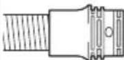 -with snap-on part -with snap-on part | Replace the hose with the one for dust extraction (ø28 mm, with front cuff). |
| ø38 mm |  with snap-on part with snap-on part | Replace the hose with the one for dust extraction (ø28 mm, with front cuff). |
 with front cuff 38 with front cuff 38 | Attach the joint 22-38 or the front cuff 24. |
NOTE: Always use a suitable front cuff. When using the front cuff 24, attach it to the front cuff 22 that is connected to the hose.
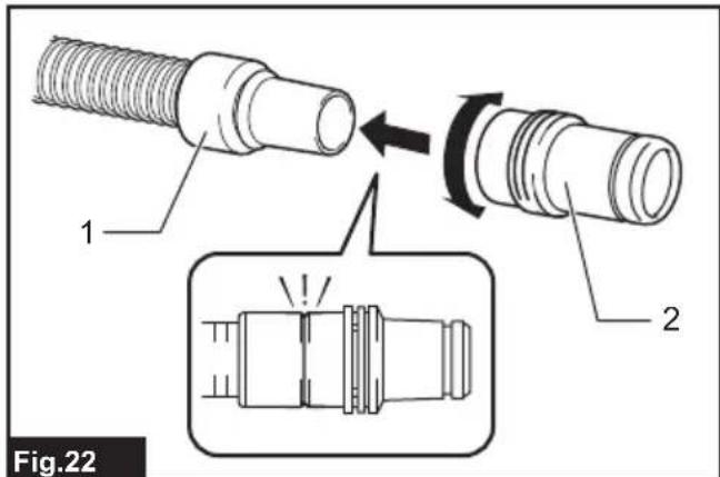
text_image
Fig.22▶ 1. Front cuff 22 2. Front cuff 24
When using 28 mm dust extraction hose
- Attach the front cuff to the hose for dust extraction. When connecting the front cuff, make sure that it is securely screwed on the hose.
- Connect the front cuff to the tool's extraction outlet.
text_image
Technical diagram showing a person using a hose and valve, with labeled parts 1, 2, and 3 illustrating mechanical assembly or installation.Fig.23
▶ 1. Front cuff 2. Extraction outlet 3. Hose
The front cuff can be detached by turning it counterclockwise while holding the hose.
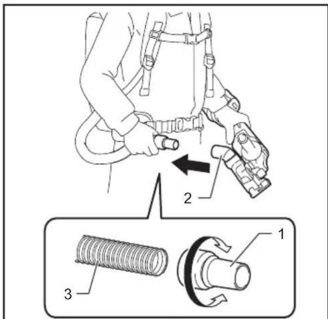
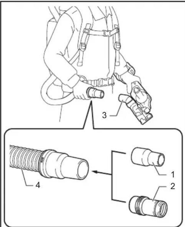
When using 38 mm hose with front cuff 38
- Twist and insert the joint or the front cuff to the inlet part on the hose, depending on the tool that you are going to connect.
- Connect the front cuff to the tool's extraction outlet.
text_image
Technical diagram showing a medical or industrial device with labeled parts including hoses and tubing, including numbered annotations.Fig.24
▶ 1. Joint 2. Front cuff 3. Extraction outlet 4. Hose
To remove the joint and the front cuff, follow the installation procedures in reverse.
Installing filter bag / dust bag
Optional accessory
CAUTION: Do not use a damaged filter bag. Always use the vacuum cleaner with the filter bag properly installed. Otherwise the vacuumed dust or particles may be exhausted from the cleaner and they may cause respiratory disease to the operator.
NOTICE: When the filter bag is already full, replace with new one. When the dust bag is already full, empty it. Continuous use with the filter bag/dust bag full results in reduced suction power.
NOTICE: To prevent dust from getting into the motor:
— Make sure that the filter bag/dust bag is installed before use.
— Do not use a broken or ripped bag.
Otherwise the motor may be broken.
NOTICE: Do not fold the cardboard at its opening when installing the filter bag/dust bag.
NOTICE: The filter bag/dust bag for the cleaner is an important component for maintaining the appliance performance. Using non-genuine filter bag/dust bag may cause smoke or ignition.
NOTE: When the filter bag/dust bag is not installed in the cleaner, the front cover does not close completely.

text_image
Fig.25- Unlock the lever and open the dust box cover.
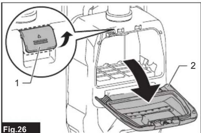
text_image
1 2 Fig.26▶ 1. Lever 2. Dust box cover
- Insert the filter bag into the slit on the upper side of the room as illustrated.

text_image
1 2 Fig.27▶ 1. Slit 2. Filter bag
When using the dust bag, insert the brim of the dust bag into the slit.
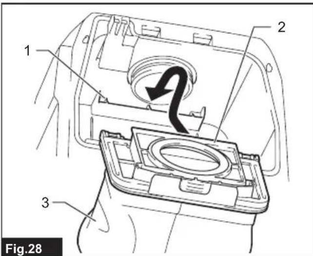
text_image
1 2 3 Fig.28▶ 1. Slit 2. Brim 3. Dust bag
- Align the hole of the filter bag with the hose cuff and push the cardboard portion to the end. Make sure that the rubber ring on the filter bag goes over the rim on the hose cuff.
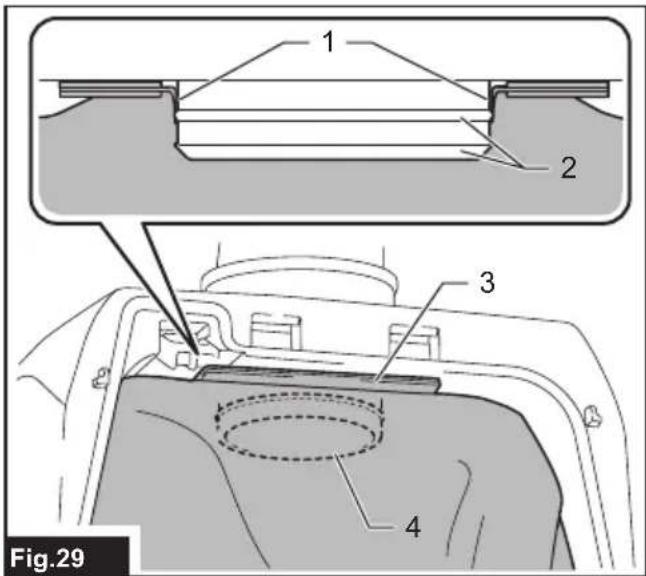
text_image
1 2 3 4 Fig.29▶ 1. Rubber ring on the filter bag 2. Rim on the hose cuff 3. Cardboard portion of the filter bag 4. Hose cuff
- Lock the dust box cover certainly.
⚠️CAUTION: Be careful not to pinch your fingers when hooking the latch, and when closing the dust box cover.
OPERATION
WARNING: Operators shall be adequately instructed on the use of the vacuum cleaner.
WARNING: This vacuum cleaner is not suitable for picking up hazardous dust.
⚠️CAUTION: This cleaner is for dry use only.
⚠CAUTION: Always insert the battery cartridge all the way until it locks in place. If you can see the red indicator on the upper side of the button, it is not locked completely. Insert it fully until the red indicator cannot be seen. If not, it may accidentally fall out of the tool, causing injury to you or someone around you.
⚠CAUTION: During operation, be conscious of the vacuum cleaner on your back. You may lose your balance if the vacuum cleaner body bumps against a wall or the hose is hooked by an obstacle.
- Shoulder the vacuum cleaner body and fasten lower and upper belts. Adjust the tightness as necessary.
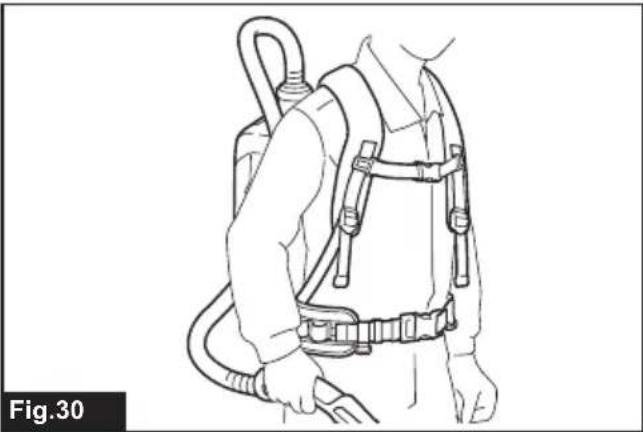
natural_image
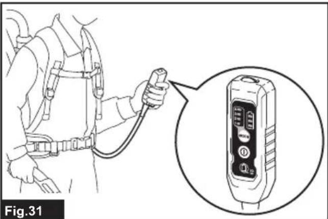
Line drawing of a person wearing a full-body safety harness (no text or symbols)- Press ① button to start vacuuming. If you want to change the suction power, press button until the desired suction power is selected. Press button to stop.
text_image
Fig.31During the operation, hook the switch box on the D-ring or the loop on the lower belt. The hook can be slanted for lighting forward when hooked on the loop.

text_image
1 2 Fig.32- D-ring 2. Loop
NOTE: The vacuum cleaner and the LED light will automatically switches off when the appliance / battery protection system works due to the overheat of the appliance / battery, or the reduced air-flow into the machine caused by clogged hose, pipe, filter or other reasons. In this case, remove the cause of the problem before restarting. For more information, refer to the section "Appliance / battery protection system".
- Replace the filter bag when it becomes full. Open the lid and take out the filter bag. Pull the strip on the side of the opening to shut the filter bag and dispose of the filter bag in whole.

text_image
Fig.33 1- Strip
When using a dust bag, take out the dust bag and dispose of the dust by releasing the latch.
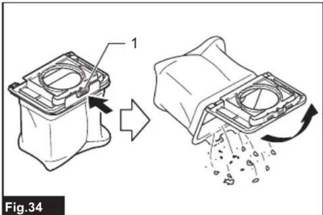
text_image
1 Fig.34- Latch
NOTICE: Periodically check the filter bag if it is full. Continuous use with the filter bag full results in reduced suction power.
NOTICE: Do not use an used filter bag. The filter bag is designed for single use. Using filter bag repeatedly may cause clogging of the filter and results in damage to the cleaner. If you want to use the bag repeatedly, use a dust bag.
MAINTENANCE
CAUTION: Always be sure that the appliance is switched off and the battery cartridge is removed before attempting to perform inspection or maintenance.
NOTICE: Never use gasoline, benzine, thinner, alcohol or the like. Discoloration, deformation or cracks may result.
To maintain product SAFETY and RELIABILITY, repairs, any other maintenance or adjustment should be performed by Makita Authorized or Factory Service Centers, always using Makita replacement parts.
Cleaning the HEPA filter
CAUTION: Do not use the vacuum cleaner without a HEPA filter or continue to use dirty or damaged HEPA filter. Vacuumed dust or particles may be exhausted from the cleaner and they may cause respiratory disease to the operator.
NOTICE: To keep optimum suction power and clean exhaust, clean the HEPA filter periodically. If enough suction power is not obtained even after the cleaning, replace the HEPA filter with new one.
NOTICE: To prevent the HEPA filter from being damaged, do not use following tools and similar items for cleaning :
— Air duster
— High pressure washer
— Tools made of hard materials such as a metallic brush
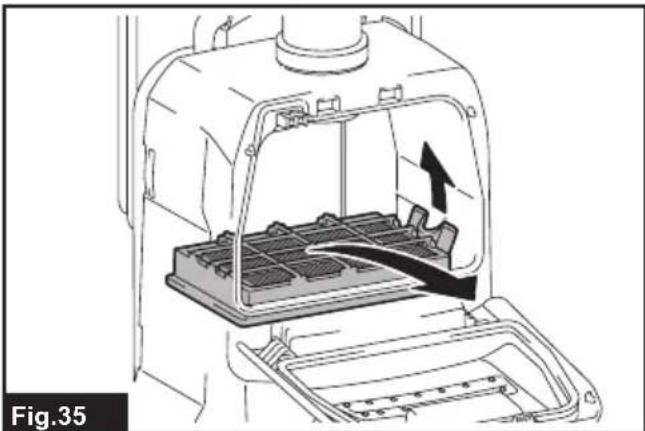
- Open the lid and take out the filter bag. Release the hook on the HEPA filter and remove it from the vacuum cleaner body.
natural_image
Technical line drawing of a mechanical device with internal components and an upward arrow indicating motion (no text or symbols)-
Beat the dust off from the HEPA filter. The HEPA filter can be washed with water. Rinse away the dust and particles on the HEPA filter every 1 or 2 month. After that, dry the HEPA filter completely in a shaded and well-ventilated place to prevent unpleasant odor or malfunctions.
-
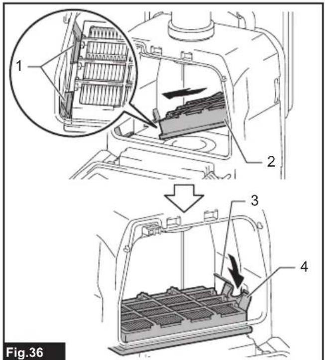
To install the HEPA filter, insert the side without the flap into the holder then push the HEPA filter downward until the flap is secured by the rib.
text_image
1 2 3 4 Fig.36▶ 1. Holder 2. HEPA filter 3. Rib 4. Flap
Cleaning the dust bag
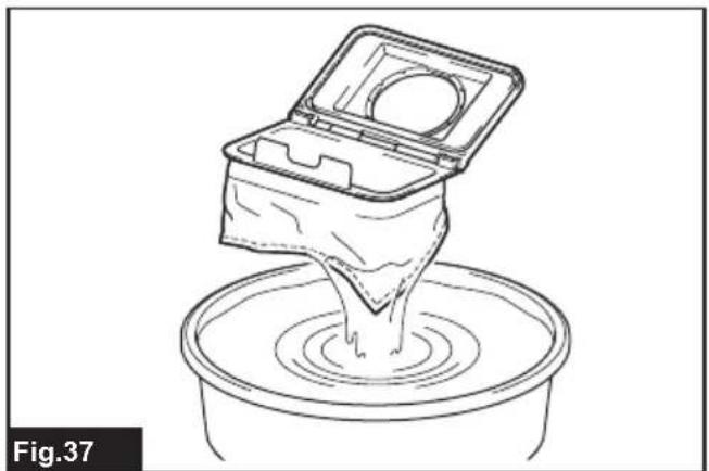
Regularly clean the dust bag with soap and water. Turn the dust bag inside out and remove the sticky dust. Wash lightly by hand and rinse well with water. Dry completely before installing to the vacuum cleaner.
natural_image
Line drawing of a container pouring liquid into a basin (no text or symbols)NOTICE: Wet dust bag lowers the vacuuming performance as well as the life of the motor.
Clearing the clog
When clearing the clog, remove the hose or the extension wand, or the bent pipe assembly to check inside.
Removing/attaching the snap-on type bent pipe assembly
To remove, pull the bent pipe assembly while pressing both of the tab on the hose end.
To attach, insert the hose end into the bent pipe assembly. Make sure that the tabs on the hose end snap into the holes on the bent pipe assembly.

text_image
Fig.38▶ 1. Hose end 2. Tab 3. Hole 4. Bent pipe assembly
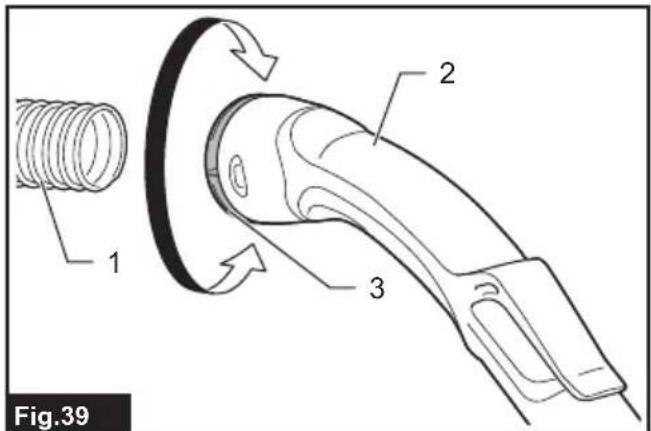
Removing/attaching the screw-in type bent pipe assembly
To remove, loosen the sleeve of bent pipe assembly from the hose.
To attach, fasten the sleeve of bent pipe assembly onto the hose.
text_image
Fig.39 1 2 3▶ 1. Hose 2. Bent pipe assembly 3. Sleeve
OPTIONAL ACCESSORIES
CAUTION: These accessories or attachments are recommended for use with your Makita tool specified in this manual. The use of any other accessories or attachments might present a risk of injury to persons. Only use accessory or attachment for its stated purpose.
If you need any assistance for more details regarding these accessories, ask your local Makita Service Center.
- Hose (for vacuum cleaner type)
- Hose (for dust extraction type)
- Extension wand
- Free nozzle
- T-shape nozzle
-
Seat nozzle
-
Corner nozzle
- Shelf brush
- Round brush
- Bent pipe assembly
- Filter bag
- Dust bag
- Front cuff
- HEPA filter
- Pipe
- Harness cover
- Cyclone attachment
- Makita genuine battery and charger
NOTE: Some items in the list may be included in the tool package as standard accessories. They may differ from country to country.
Cyclone attachment
NOTE: When using the cyclone attachment with this appliance, the bent pipe is also required.

text_image
1 Fig.40▶ 1. Cyclone attachment
About the cyclone attachment
Using the cleaner with the cyclone attachment installed reduces the amount of dust that enters the dust bag, which helps to prevent the suction force from weakening. In addition, cleaning after use is also simple.
⚠️CAUTION: Always be sure that the tool is switched off and the battery cartridge is removed before carrying out any work on the tool. If the battery cartridge is left inserted, the cleaner may start unexpectedly and result in injury.
⚠CAUTION: Clean the mesh filter of the cyclone attachment and the dust bag of the cleaner unit when they become clogged.
Continued use in the clogged condition may result in heating or smoke.
NOTICE: When the cyclone attachment is attached, do not use the cyclone attachment in the horizontal or upward facing condition. Doing so may cause the mesh filter to become clogged.
NOTICE: Always use the cleaner with the dust bag installed, even when using the cyclone attachment. Using the cleaner without the dust bag installed may result in a motor malfunction.
NOTE: Check that the cyclone attachment, cleaner, and straight pipe are locked properly before use.
NOTE: Empty the dust case of the cyclone attachment and the dust bag of the cleaner when dust has accumulated. Continued use will result in weakened suction force.
NOTE: You can use the cyclone attachment with or without lock function.
NOTE: To install or remove the cyclone attachment, refer to the section "Using as a cleaner".
Disposing of dust
When dust has accumulated up to the full line of the dust case, follow the procedure below and dispose of the dust.
- Hold the dust case firmly, press and hold the two buttons, and remove the dust case.

text_image
Fig.41 1 2 3 4 ① ②▶ 1. Full line 2. Dust case 3. Button (two locations) 4. Mesh filter
-
Dispose of the dust inside the dust case and remove any dust and powder adhered to the surface of the mesh filter.
-
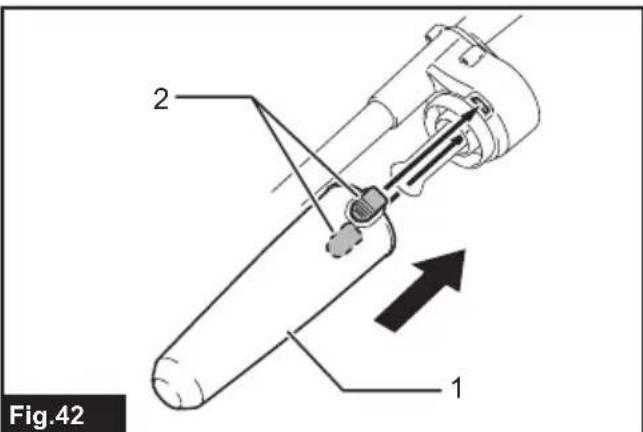
Insert the dust case all the way until the two buttons lock with a click.
text_image
Fig.42 1 2▶ 1. Dust case 2. Button (two locations)
NOTE: Check that the cyclone attachment, cleaner, and straight pipe are locked properly before restarting operation.
NOTE: If the suction force does not recover even after disposing of the dust and cleaning the mesh filter, check whether dust has accumulated in the dust bag of the cleaner or clogging has occurred.
Cleaning
When the dust case becomes dirty or the mesh filter is clogged, remove and wash them with water. (Refer to "Disposing of dust" for the removal procedure.)
Dry the parts thoroughly before reinstallation and use.

text_image
1 2 Fig.43▶ 1. Dust case 2. Mesh filter
When the mesh filter gets dirty badly, clean it in the following procedures.
- Turn the mesh filter counterclockwise and remove it while the hooks are unlocked.

text_image
Fig.44▶ 1. Mesh filter 2. Hook
-
Remove the dust on the mesh filter and then wash it with water. After that, dry it thoroughly.
-
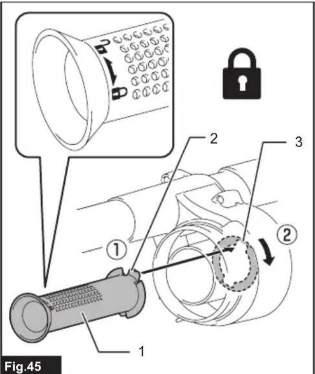
Insert the mesh filter into the base while the hooks are aligned with the port. Turn the mesh filter clockwise until the hooks are locked with a click. Make sure that the mesh filter is installed securely.
text_image
Fig.45 1 2 3 2 1▶ 1. Mesh filter 2. Hook 3. Port
MAKITA LIMITED WARRANTY
Please refer to the annexed warranty sheet for the most current warranty terms applicable to this product. If annexed warranty sheet is not available, refer to the warranty details set forth at below website for your respective country.
United States of America: www.makitatools.com
Canada: www.makita.ca
Other countries: www.makita.com
ESPECIFICACIONES
text_image
Diagram showing a device with labeled parts and two separate devices, likely illustrating a mechanical or electrical assembly.text_image
1 2 Fig.3text_image
1 2 Fig.4▶ 1. Correa 2. Sujetador
Correas para hombro
text_image
Fig.5 1 2- Correa 2. Sujetador
Correa superior
text_image
Fig.6 1 2- Correa 2. Sujetador
Gancho de sujeción
natural_image
Technical diagram of a car seatbelt device with labeled component (no text or symbols beyond label)- Gancho de sujeción
text_image
1 2 MODOC Fig.8text_image
Fig.10 1 2 3- Abrazadera de la manguera 2. Ranura 3. Manguera
text_image
Fig.11 1 2 1 2 1- Bucle 2. Boquillas
text_image
1 2 3 4 Fig.15▶ 1. Tubo de extensión 2. Boquilla amplia 3. Boquilla T 4. Boquilla T (delgada)
text_image
Technical diagram showing a hand holding a tool with labeled parts, including a 3D view and a close-up of the tool's internal structure.Fig.16
text_image
Technical diagram showing a person using a tool to adjust or install a cylindrical device, with labeled parts 1, 2, and 3.Fig.18
text_image
Fig.20 1 2 3 4- Boca delantera 38 2. Tubo curvo de aluminio
- Tubo recto de aluminio 4. Boquilla
text_image
Technical diagram showing a person using a safety harness to adjust a tool, with labeled parts 1, 2, and 3.Fig.21
text_image
Technical diagram showing a person wearing a harness and connected to two labeled cylindrical components with numbered parts.Fig.24
text_image
1 2 Fig.26text_image
1 2 Fig.27▶ 1. Hendidura 2. Bolsa del filtro
text_image
1 2 3 Fig.28▶ 1. Hendidura 2. Reborde 3. Bolsa recolectora de polvo
text_image
1 2 3 4 Fig.29natural_image
Line drawing of a person wearing a full-body safety harness (no text or symbols)natural_image
Illustration of a person in full-body safety harness using a handheld device, with an inset close-up showing the device's internal components (no text or symbols)text_image
1 2 Fig.32natural_image
Technical line drawing of a mechanical device with internal components and an arrow indicating motion (no text or symbols)text_image
1 2 3 4 Fig.36▶ 1. Soporte 2. Filtro HEPA 3. Varilla 4. Lengüeta
natural_image
Line drawing of a container with liquid being poured into a basin (no text or symbols)natural_image
Illustration of a handheld device with a close-up inset showing its mechanical components (no text or symbols)- Colector ciclónico
text_image
Fig.41 1 2 3 4 ① ②text_image
Fig.42 1 2text_image
1 2 Fig.43▶ 1. Caja para polvo 2. Filtro de malla
Some dust created by power sanding, sawing, grinding, drilling, and other construction activities contains chemicals known to the State of California to cause cancer, birth defects or other reproductive harm. Some examples of these chemicals are:
- lead from lead-based paints,
• crystalline silica from bricks and cement and other masonry products, and
• arsenic and chromium from chemically-treated lumber.
Your risk from these exposures varies, depending on how often you do this type of work. To reduce your exposure to these chemicals: work in a well ventilated area, and work with approved safety equipment, such as those dust masks that are specially designed to filter out microscopic particles.