
92-3300P - Installation Kit Metra - Free user manual and instructions
Find the device manual for free 92-3300P Metra in PDF.

| Product Type | Installation Kit |
| Brand | Metra |
| Model | 92-3300P |
| Category | Car Audio Installation Kit |
| Compatible Vehicles | Chevrolet (specific models not listed, likely 2003 era) |
| Compatible Receiver Types | DIN and Shaft-Mount Receivers |
| Parts Included | Kit frame, trimplate, support tray, mounting brackets (4), 1/4 inch hex screws (4), studs (2), 3/8 inch nuts (2) |
| Material | Plastic (kit frame and trimplate), metal (brackets and hardware) |
| Color | Black (typical) |
| Dimensions (Kit Frame) | Approximately 7 x 5 x 2 inches (estimated for DIN standard) |
| Weight | Approximately 0.5 lb (0.23 kg) |
| Installation Difficulty | Moderate; requires basic tools and careful trimming for some models |
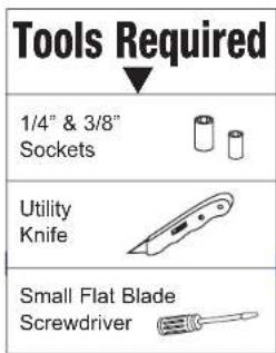
| Tools Required | Utility knife, hex key (or small wrench), screwdriver |
| Additional Hardware Required (not included) | Shaft nuts and spacers for shaft-mount receivers (supplied by receiver manufacturer) |
| Documentation | Free PDF manual available (3 pages, English) |
| Special Features | Supports both DIN and shaft-mount installations; trimplate can be cut to create DIN opening |
| Safety | Use appropriate tools and ensure secure mounting to avoid vibration |
| Compliance | Meets aftermarket installation standards |
Frequently Asked Questions - 92-3300P Metra
User questions about 92-3300P Metra
0 question about this device. Answer the ones you know or ask your own.
Ask a new question about this device
Download the instructions for your Installation Kit in PDF format for free! Find your manual 92-3300P - Metra and take your electronic device back in hand. On this page are published all the documents necessary for the use of your device. 92-3300P by Metra.
USER MANUAL 92-3300P Metra
Before starting, compare items on your invoice with items received. Carefully check through packaging material.
If an item is missing, please call:
Crutchfield at 1-888-955-6000
120 92-3300P
Chevrolet
Revision 09/17/03
Parts Supplied:
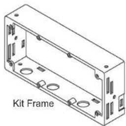
natural_image
Isometric line drawing of a rectangular enclosure with multiple circular holes and mounting holes (no text or symbols)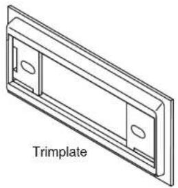
natural_image
Technical line drawing of a trimplate component (no text or symbols)
natural_image
Isometric line drawing of a support tray component (no text or symbols on the diagram itself)
Mounting Brackets

(4) 1/4" Hex Screws
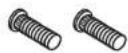
(2) Studs

(2) 3/8" Nuts
Kit assembly instructions are on the following pages.

CRUTCHFIELD®
Copyright 2003 Crutchfield Corporation
Installation Kit
120 92-3300P
Chevrolet
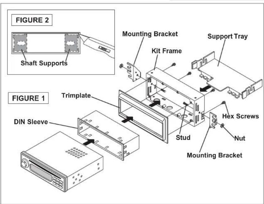
DIN Receiver Assembly
- Press posts on trimplate into holes on kit frame to snap parts together and secure with hex screws (Figure 1).
- Use a utility knife to cut out shaft supports in trimplate to create a DIN opening (Figure 2).
- Push clips on support tray into slots on rear of kit frame to secure (Figure 1).
- Secure side mounting brackets to kit frame with studs and nuts supplied (Figure 1).
- Remove DIN sleeve from receiver and slide into opening in trimplate. Secure sleeve to trimplate by bending the securing tabs (Figure 3).
- Slide receiver into sleeve/kit assembly.

CRUTCHFIELD®
Copyright 2003 Crutchfield Corporation
Installation Kit
120 92-3300P
Chevrolet
Shaft Receiver Assembly
- Press posts on trimplate into holes on kit frame to snap parts together and secure with hex screws (Figure 1).
- Push clips on support tray into slots on rear of kit frame to secure (Figure 1).
- Secure side mounting brackets to kit assembly with studs and nuts supplied (Figure 1).
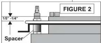
- Choose the proper spacers (supplied with your order) to allow receiver nosepiece to extend 1/8" to 1/4" beyond face of trimplate (Figure 2).
- Insert receiver shafts (with spacers in place) through openings in trimplate. Secure receiver and faceplate with shaftnuts supplied with receiver.
- Attach control knobs.
FIGURE 1


CRUTCHFIELD®
Copyright 2003 Crutchfield Corporation


Brand : Metra
Model : 92-3300P
Category : Installation Kit