PrimeSHOT - Video Conferencing System LEGRAND - Free user manual and instructions
Find the device manual for free PrimeSHOT LEGRAND in PDF.

User questions about PrimeSHOT LEGRAND
0 question about this device. Answer the ones you know or ask your own.
Ask a new question about this device
Download the instructions for your Video Conferencing System in PDF format for free! Find your manual PrimeSHOT - LEGRAND and take your electronic device back in hand. On this page are published all the documents necessary for the use of your device. PrimeSHOT by LEGRAND.
USER MANUAL PrimeSHOT LEGRAND
natural_image
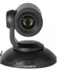
Black Vaddi camera on a stand with blue background (no text or symbols visible)Complete Manual for the
PrimeSHOT 20 HDMI
PTZ Camera
Document 411-0022-30 Rev B
July 2018
Contents
Overview 1.
What's in this Guide.1....
Features 1
Unpacking the Camera 2.
A Quick Look at the Camera.3....
Front of the Camera 3.
Back of the Camera 4.
Video Resolution Setting 4
Installation 5
Before You Install the Camera.5....
Don't Void Your Warranty! 5.
Cabling Notes.5....
Installing the Thin Profile Wall Mount 6
About Ceiling-Mounted Cameras 6
Basic Connection Diagram.... 6
RS-232 Serial Communication....7
Installing the Camera 8
Powering Up the Camera....9
Status Light 9
Using the Remote Control 10
Quick Reference 10
Details 11
Storing a Preset Using the Remote 11
Clearing a Preset Using the Remote 11
Web Interface 12
Browser Support 12
User Access 13
Administrative Access 13
Web Interface Quick Reference 14
Compact Menu View 14
System Administration 15
Configuring Network Settings.... 15
Setting Time Zone and NTP Server 16
Managing Access and Passwords 17
Adding Room Information to the Screen 18
Rebooting the Camera 19
Saving or Restoring a Configuration 19
Starting a Firmware Update 20
Contacting Vaddio Technical Support 21
Viewing Diagnostic Logs 21
Configuring Camera Behavior 22
Storing Preset Positions Including Custom Home 22....
Adjusting the Color Settings 23
Adjusting the Focus 24
Setting the Speeds of Camera Movements 24.
Setting Pan Direction 24
Enabling or Disabling Streaming 25
Configuring IP Streaming 26
Advanced IP Streaming Settings 28
Setting Other Camera Behaviors 29
Operating the Camera 30
Moving the Camera 30
Zooming In or Out 30
Moving the Camera to a Preset Position 30
Stopping or Resuming Video 31
Managing the Camera Ready State 31
Telnet Serial Command API 32
camera home 33
camera pan 33
camera tilt 34
camera zoom 35
camera focus 35
camera preset 36
camera ccu get 37
camera ccu set 38
camera ccu scene 39
camera led 39
camera recalibrate 39
camera standby 40
video mute 40
streaming settings get 41
network settings get 41
network ping....42
system reboot 42
system factory-reset 43
version 43
help 44
history 44
exit 44
RS-232 Control 45
Camera Movement, Zoom, and Focus Commands 45
Movement, Zoom, and Focus Inquiry Commands 47
Color and Light Management Commands 48
Shutter Speed Values (CAM_Shutter).50
Iris Values (CAM_Iris).51
Iris Gain and Gain Limit Values (CAM_Gain).51.
Color and Light Management Inquiry Commands 52
Other Commands 52
Other Inquiry Commands 53
Specifications 54
Troubleshooting and Care 55
Status Light 56
Restoring Default Camera Settings 57
Operation, Storage, and Care 57
Compliance Statements and Declarations of Conformity 58
FCC Part 15 Compliance 58
ICES-003 Compliance 58
European Compliance 59
Warranty Information 60
Photo Credits 61
Index 62
Overview
This guide covers the PrimeSHOT™ 20 HDMI PTZ camera:
■ PrimeSHOT 20 HDMI (black), North America – 999-30420-000
■ PrimeSHOT 20 HDMI (white), North America – 999-30420-000W
■ PrimeSHOT 20 HDMI (black), Europe and UK – 999-30420-001
■ PrimeSHOT 20 HDMI (white), Europe and UK–999-30420-001W
■ PrimeSHOT 20 HDMI (black), Australia and New Zealand – 999-30420-009
■ PrimeSHOT 20 HDMI (white), Australia and New Zealand – 999-30420-009W
■ PrimeSHOT 20 HDMI (black) with HDMI Extenders, North America – 999-30 300
■ PrimeSHOT 20 HDMI (white) with HDMI Extenders, North America – 999-30420-300W
■ PrimeSHOT 20 HDMI (black) with HDMI Extenders, Europe and UK – 999-30420-301
■ PrimeSHOT 20 HDMI (white) with HDMI Extenders, Europe and UK – 999-30420-301W
■ PrimeSHOT 20 HDMI (black) with HDMI Extenders, Australia and New Zealand – 999-30420-309
■ PrimeSHOT 20 HDMI (white) with HDMI Extenders, Australia and New Zealand – 999-30420-309W
natural_image
Close-up of a black audio recording device with a lens and stand (no visible text or symbols)What's in this Guide
This guide covers
■ Unpacking and installation
■ The system's physical features
■ Configuration and system administration
■ Controlling the camera using the IR remote or web interface
■ Controlling the camera using Telnet or RS-232 commands
■ Specifications
■ Troubleshooting and maintenance
■ Warranty and compliance/conformity information
For your convenience, the information you need to install this product is also available in the smaller, standalone Installation Guide for the PrimeSHOT 20 HDMI PTZ Camera.
Download manuals, dimensional drawings, and other information from www.vaddio.com/support.
Features
■ PTZ camera for medium to large venues such as houses of worship and lecture theaters
■ 2.12 Megapixel effective, native 1080p/60 full HD image sensor
■ 20x optical zoom, 55° horizontal field of view (wide end)
■ Simultaneous HDMI 1.3, S-Video, and IP streaming outputs
■ Precise pan and tilt movements at up to 90° per second
■ Presenter-friendly IR remote control
■ Integration-ready Telnet or serial RS-232 control
■ Full administrative control via web interface; manage the camera remotely while monitoring the stream separately
Unpacking the Camera
Make sure you received all the items you expected.


Caution
Always support the camera's body when lifting or moving it. Lifting the camera by its head or will damage it.
999-30420-000 - PrimeSHOT 20 HDMI (black), North America
999-30420-000W - PrimeSHOT 20 HDMI (white), North America
999-30420-001 - PrimeSHOT 20 HDMI (black), Europe and UK
999-30420-001W - PrimeSHOT 20 HDMI (white), Europe and UK
999-30420-009 - PrimeSHOT 20 HDMI (black), Australia and New Zealand.
999-30420-009W - PrimeSHOT 20 HDMI (white), Australia and New Zealand
■ PrimeSHOT 20 HDMI camera
■ Thin Profile Wall Mount with mounting hardware
■ Vaddio IR Remote Commander
■ 12 VDC, 3.0 Amp power supply with AC cord set(s)
■ Quick-Start Guide

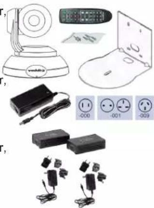
natural_image
Illustration of various household appliances including a remote control, switch, battery pack, and electrical outlets (no text or symbols visible)999-30420-300 - PrimeSHOT 20 HDMI (black) with HDMI Extender, North America
999-30420-300W - PrimeSHOT 20 HDMI (white) with HDMI Extender North America
999-30420-301 - PrimeSHOT 20 HDMI (black) with HDMI Extender, Europe and UK
999-30420-301W - PrimeSHOT 20 HDMI (white) with HDMI Extender, Europe and UK
999-30420-309 - PrimeSHOT 20 HDMI (black) with HDMI Extender, Australia and New Zealand
999-30420-309W - PrimeSHOT 20 HDMI (white) with HDMI Extender, Australia and New Zealand
■ PrimeSHOT 20 HDMI camera
■ Thin Profile Wall Mount with mounting hardware
■ Vaddio IR Remote Commander
■ 12 VDC, 3.0 Amp power supply with AC cord set(s)
■ Quick-Start Guide
■ C2G HDMI Extender Transmitter unit
■ C2G HDMI Extender Receiver unit
■ 5VDC 1.0A Extender power supply with regional plugs, quantity 2
■ 1 ft (0.3 m) HDMI cable
■ C2G HDMI Extenders User Booklet
natural_image
Product catalog image showing various electronic devices and accessories (no readable text or symbols)A Quick Look at the Camera
This section covers the physical features of the camera.
Front of the Camera
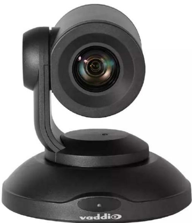
natural_image
Black Vaddi camera on a tripod stand, no visible text or symbols on the device bodyCamera and Zoom Lens: The PrimeSHOT 20 HDMI camera features a 20x optical zoom lens.
IR sensor: Receives signals from the IR remote. Make sure there's nothing directly in front of the camera base, and point the remote at the camera.
Status light: The multi-colored LED indicates the camera's current state. This light can be turned off.
■ Blue - Camera is active
■ Red - Tally
■ Purple – Standby mode or booting
■ Yellow – Firmware update is in progress
■ Blinking red – Video mute is on (UC color scheme only)
■ Blinking yellow – Motor out of calibration
■ Blinking purple - Error
Note
By default, the camera's status light is active during normal operation; however, it can be configured to remain off when the camera is powered up. The camera may be sending video even if the inc off.
Back of the Camera
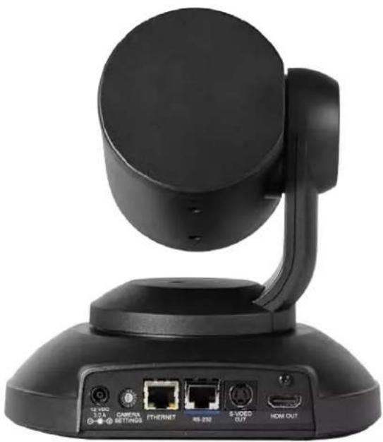
natural_image
Black remote control device with ports and antenna (no visible text or symbols)From left to right:
■ Power connector – Connect the 12 VDC, 3 A power supply shipped with the camera.
- Rotary switch – Select the video output resolution.
- Ethernet connector – Connect to the network.
■ RS-232 connector – Optional. Connect to a camera controller to manage the camera.
■ S-Video connector - S-Video output; can be set to NTSC or PAL.
■ HDMI connector - HDMI 1.3 video output.
Video Resolution Setting
Use the rotary switch on the back of the camera to set the desired HDMI output resolution.
| 0 | 720p/59.94 | B | 1080p/50 |
| 1 | 1080i/59.94 | 9 | |
| 2 | 1080p/59.94 | A | |
| 3 | 720p/60 | B | |
| 4 | 1080i/60 | C | |
| 5 | 1080p/60 | D | |
| 6 | 720p/50 | E | |
| 7 | 1080i/50 | F |
The S-Video output can be set to PAL or NTSC in the administrative interface (see Setting Other Camera Behaviors). Default is NTSC.
Installation
This section covers:
■ Selecting the location for the camera
■ Installing the mount
■ Connecting the camera
■ Mounting the camera
Before You Install the Camera
- Choose a mounting location that will optimize camera performance. Consider camera viewing angles,
lighting conditions, line-of-sight obstructions, and in-wall obstructions where the camera is to be mounted.
■ Ensure that the camera body can move freely and will normally point away from the ceiling and lights.
The camera will not perform well if it is pointed toward a light source such as a light fixture or window.
■ Follow the installation instructions included with the camera mount.
Don't Void Your Warranty!
Caution
This product is for indoor use. Do not install it outdoors or in a humid environment without the protective enclosure. Do not allow it to come into contact with any liquid.
Use only the power supply included with this product. Using a different one will void the warran could create unsafe operating conditions or damage the product.
Do not install or operate this product if it has been dropped, damaged, or exposed to liquids. It is things happen, return it to Vaddio for safety and functional testing.
Cabling Notes
Note
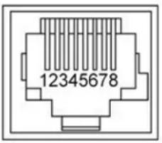
Use standard RJ-45 connectors and a good crimping tool. Do not use pass-through RJ-45 connectors. Poorly crimped connectors can damage the connectors on the product, cause intermittent connections, and degrade signal quality. Test cable pin-outs and continuity before connected them.
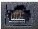
Intact - will make reliable contact with cable connector
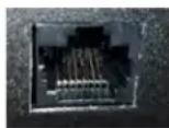
Damaged – Bent contact fingers will NOT make reliable contact with cable connector
Pro Tip
Label all cables at both ends.
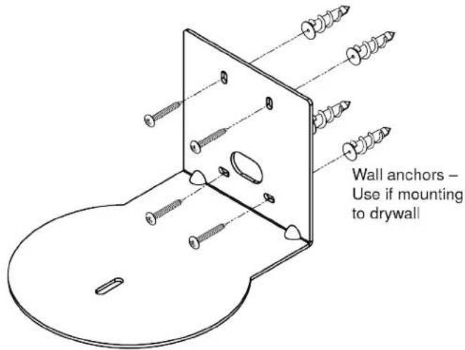
Installing the Thin Profile Wall Mount
The PrimeSHOT 20 HDMI camera is shipped with a Thin Profile Wall Mount. Other mounting options are available as well. Contact us if you don't have the camera mount you need.
You can install the camera wall mount to a 2-gang wall box or directly to the drywall.
■ If you mount it to drywall, use the wall anchors provided with the wall mount.
■ If you mount it to a wall box, use the cover plate screws supplied with the wall box.
If you install the camera wall mount to drywall, use the wall anchors provided with the mount.
About Ceiling-Mounted Cameras
If you use an inverted mount, set the camera's Image Flip soft DIP switch ON. See Setting Other Camera Behaviors.
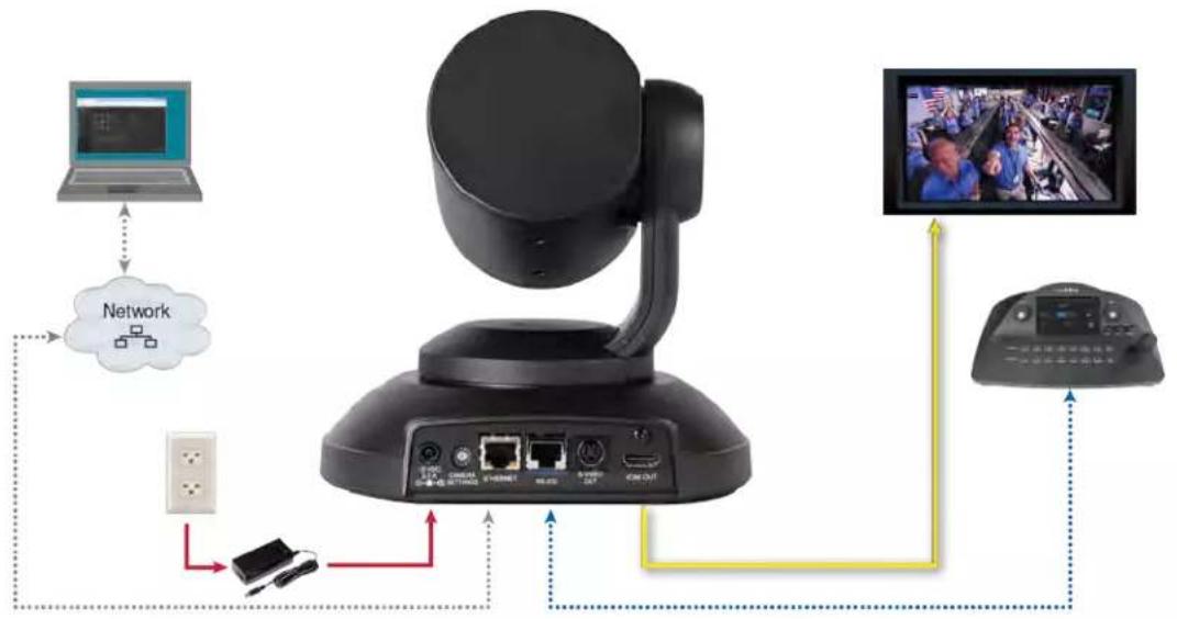
Basic Connection Diagram
The Quick-Start Guide for the PrimeSHOT 20 HDMI PTZ Camera provides additional information.
flowchart
graph TD
    A["Desktop"] --> B["Network"]
    B --> C["Port 1"]
    B --> D["Port 2"]
    B --> E["Port 3"]
    B --> F["Port 4"]
    B --> G["Port 5"]
    B --> H["Port 6"]
    B --> I["Port 7"]
    B --> J["Port 8"]
    B --> K["Port 9"]
    B --> L["Port 10"]
    B --> M["Port 11"]
    B --> N["Port 12"]
    B --> O["Port 13"]
    B --> P["Port 14"]
    B --> Q["Port 15"]
    B --> R["Port 16"]
    B --> S["Port 17"]
    B --> T["Port 18"]
    B --> U["Port 19"]
    B --> V["Port 20"]
    B --> W["Port 21"]
    B --> X["Port 22"]
    B --> Y["Port 23"]
    B --> Z["Port 24"]
    B --> AA["Port 25"]
    B --> AB["Port 26"]
    B --> AC["Port 27"]
    B --> AD["Port 28"]
    B --> AE["Port 29"]
    B --> AF["Port 30"]
RS-232 Serial Communication
The RS-232 serial port (RJ-45, color-coded blue) on the camera's back panel enables third-party control.
| Parameter Value | |
| Communication Speed 9600 bps (default) | |
| Number of start bits 1 | |
| Number of stop bits 1 | |
| Number of data bits 8 | |
| Parity None | |
| Flow control None |
Connector pin-out:
■ Pin 1: Not used
■ Pin 2: Not used
■ Pin 3: Not used
■ Pin 4: Not used
■ Pin 5: Not used
■ Pin 6: GND
■ Pin 7: RXD (from TXD of control source)
■ Pin 8: TXD (to RXD of control source)
Caution:
Check Cat-5 cables for continuity before using them. Using the wrong pin-out may damage the c system and void the warranty. Pro tip: Label your cables.
Installing the Camera
Caution
Before you start, be sure you can identify all cables correctly. Connecting a cable to the wrong result in equipment damage.
Caution:
Check Cat-5 cables for continuity before using them. Using the wrong pin-out may damage the c system and void the warranty. Pro tip: Label your cables.
-
Verify that you have set the switch on the back of the camera to the desired video resolution.
-
Route the cables through the opening in the mounting shelf and connect them to the camera.
Caution:
Use the power supply shipped with the camera. Using a different power supply will damage the and void the warranty, and may create an unsafe operating condition.
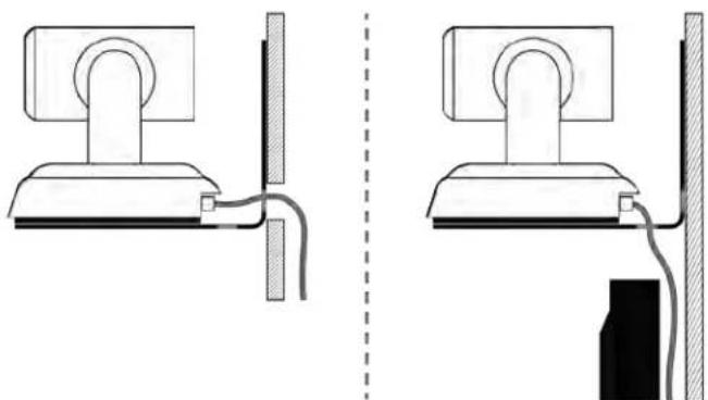
- Place the camera on the mount.
natural_image
Diagram showing two views of a computer monitor mounted on a stand, connected by wires (no text or symbols present)- Attach the camera to the mount using the mounting screw supplied with the camera.
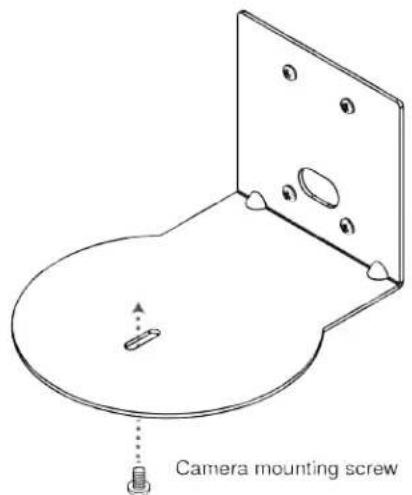
Image for illustration only; not to scale. Camera and mount details may differ.
Note
If the camera is jostled or bumped, it may require a pan-tilt reset.
Powering Up the Camera
Connect camera power.
The camera will initialize and move. This will take a few seconds. When an image is available, the camera is ready to accept control information.
Status Light
The light in the camera's base indicates its current state.
■ Blue – Camera is active
■ Purple – Standby mode or booting
■ Yellow – Firmware update is in progress
■ Blinking red – Video mute is on (UC color scheme only)
■ Blinking yellow – Motor out of calibration
■ Blinking purple - Error
Caution
Do not remove power or reset the camera while the indicator is yellow, showing a firmware upa progress. Interrupting a firmware update can make the camera unusable.
Note
By default, the camera's status light is active during normal operation; however, it can be configured to remain off when the camera is powered up. The camera may be sending video even if the inc off.
Using the Remote Control
The remote provides basic camera control.
Quick Reference
| What do you need to do? Button(s) | |
| Power on or standby Power (green button at top right) | |
| Select the camera to control (if this re controls more than one) | Camera Select buttons 1 through 3 (second row on the remote) |
| Discover the camera's IP address | Data Screen button (top left) – press and hold for 3 seconds |
| Move the camera Arrow buttons and Home button (dark red) | |
| Move the camera to a preset position | Position Preset buttons 1 through 6 (bottom two rows) |
| Focus the camera Auto Focus button | (near arrow buttons)Manual Focus buttons Near and Far (below Zoom Speed buttons) |
| Change zoom speed | Zoom speed buttons – Slow T and W or Fast T and W for telephoto (zoom in) and wide-angle (zoom out) modes (center) |
| Adjust for excess light behind the cam subject | Back Light button (top center) |
| Correct a motor calibration fault condition (blinking yellow light) | Pan-Tilt Reset button (center right, beside arrow buttons) |
Details
The remote provides the following functions:
Data Screen – Press and hold for 3 seconds to display the camera's IP addr MAC address on the near-end display. Press momentarily to dismiss the informa
Power indicator – Shows power on, IR transmission, and battery level.
Power - Switch the selected camera on or off.
Back Light - Use or turn off back light compensation.
Camera Select – In multi-camera installations, selects the camera to be contr See Setting Other Camera Behaviors for information on configuring the camera as camera 1, 2, or 3.
Pan/Tilt (arrow button) controls and Home button - Control the camera position.
Std. Pan and Rev. Pan - Control how the camera responds to the arrow Helpful for ceiling-mounted cameras and installations where the camera will point the person using the remote.
Pan/Tilt Reset – Recalibrate the pan and tilt motors. If the camera gets jostler may need to push this button to ensure that the camera moves accurately to its and preset positions.
Auto Focus - Switch the camera to Auto-Focus mode.
Zoom Speed - Select Slow or Fast movements for telephoto and wide-angle shots.
■ T (slow and fast) – Telephoto
■ W (slow and fast) – Wide-angle
Manual Focus – Switch the camera to Manual Focus mode.
Near (-) adjustment - Moves the focus nearer when in manual focus mode.
Far (+) adjustment – Moves the focus farther when in manual focus mode.
Position Presets 1 through 6 - Move the camera to a predefined position.
Preset - Save the camera's current position as one of the numbered presets.
Reset - Clear the saved position presets.
The web interface offers greater control over camera movements to presets, and provides additional presets.
Storing a Preset Using the Remote
Set up the shot using the pan, tilt, and zoom controls. Then hold down the Preset button and press one of the numbered preset buttons.
Clearing a Preset Using the Remote
Press and hold the Reset button while pressing the preset number you want to clear.

Web Interface
The camera's web interface allows control via a network connection, using a browser. Password-protected pages provide administrative access to tasks such as setting passwords, changing the IP address, viewing diagnostics, and installing firmware updates. The user login (or guest access, if it is enabled) provides access to camera controls similar to those available from the IR remote.
You will need to know the camera's IP address to use the web interface. If the LAN has a DHCP server, the camera will get its IP address, gateway and routing information automatically and you will be able to browse to it. If not, you will need to configure the camera to use a static IP address.
To display the camera's IP address:
- Point the remote at the camera and press the Data Screen button. The camera overlays its IP address and MAC address on the video output.
- Press the button again to dismiss the information display.
If the address is 169.254.1.1, the camera is using its default IP address and you will need to configure it for your network. You can configure the camera's static IP address either through the network or from a computer connected directly to its Ethernet port. You may need a crossover cable.
Note
Work with your IT department to determine the correct IP address, subnet mask, and gateway info
To access the web interface:
Enter the IP address or hostname in your browser's address bar. If you use the hostname, you may need to enter http://or https://as a prefix to keep the browser from treating it as a search query.
Browser Support
We have tested this product with these web browsers:
Chrome®
■ Microsoft® Internet Explorer®
■ Safari®
■ Firefox®
We test using the browser version available from the vendor at that time. Older versions of these browsers are likely to work, and other browsers may also work.
User Access
By default, the web interface opens to the Controls page without requiring a login; but if the administrator has changed the guest access setting, you will need to log in. The default user password is password.
Only the camera control page is available with user-level access.
Administrative Access
If you are on the Controls screen, you're logged in at the user level, or guest access is enabled and you're not logged in at all. Open the menu to log in as admin.

The default admin password is password.
Logging in as Admin gives you access to configuration and system administration tasks:
■ Camera – Additional control over camera behavior related to camera zoom and color management.
■ Streaming – Set up IP (H.264) streaming to meet your organization's requirements.
■ Room Labels – Information to display on the web interface screens, including the conference room name and phone number and the in-house number for AV assistance.
■ Networking – Ethernet configuration.
■ Security – Set passwords and manage guest access.
■ Diagnostics – View or download logs when troubleshooting issues.
■ System – View firmware version and hardware switch settings, access soft DIP switches, reboot, restore factory defaults, and run firmware updates.
- Help – Tech support contact information and a link to the product information library on the Vaddio website.
- Logout – Leave the web interface in a password-protected state. If guest access is on, this returns the web interface to the Controls page at guest access level.
Web Interface Quick Reference
Where to find the controls you need right now.
| What do you need? Go to this page | |
| Camera operation■ Stop sending video (video mute)■ Enter or exit standby mode | (any page) |
| Access management■ Guest access■ Account passwords■ Automatic logout for idle sessions | Security |
| IP streaming settings Streaming | |
| Other IP settings■ Hostname■ DHCP or static addressing■ Static: IP address, subnet mask, gateway | Networking |
| Date and time, time zone, and NTP server Networking | |
| Information about the camera■ Room location and phone number■ Help desk phone number | Room Labels |
| Vaddio Technical Support contact information Help | |
| Diagnostic logs Diagnostics |
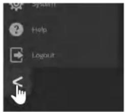
Compact Menu View
By default, the navigation buttons in the administrative interface display an icon and a text label.
The web interface provides a compact view of the menu buttons along with the standard view. The button at the bottom of the menu toggles between the two views.
System Administration
Administrative tasks are on these pages:
■ Networking – Network configuration, date/time, and time zone settings
■ Security – Passwords, guest access, other IT security-related settings
■ Room Labels – Helpful information to display in the web interface
■ System – Controls to reboot, reset to factory defaults, and run firmware updates
■ Help – Contact information for Vaddio Technical Support and links to more information
■ Diagnostics – Logs to help Vaddio Technical Support troubleshoot issues
Configuring Network Settings
NETWORKING PAGE
Caution
Consult your IT department before editing network settings. Errors in network configuration can make camera and its IP stream inaccessible from the network. Do not change DHCP/Static addressing, address, subnet mask, or gateway unless you are very familiar with the characteristics and config the network where you install the camera.
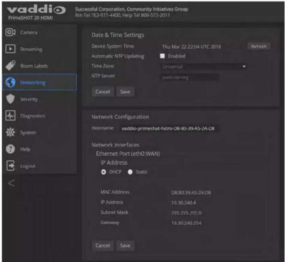
Editable network settings include:
■ The camera's hostname
■ Choice of static IP addressing or DHCP addressing
■ IP address, subnet mask, and gateway, if static IP addressing is used
If your network supports hostname resolution, you may find it convenient to change the camera's hostname.
DHCP is the default setting, but the camera will use the default address of 169.254.1.1 if no DHCP server is available. You will only be able to enter the IP address, subnet mask, and gateway if you set IP Address to Static.
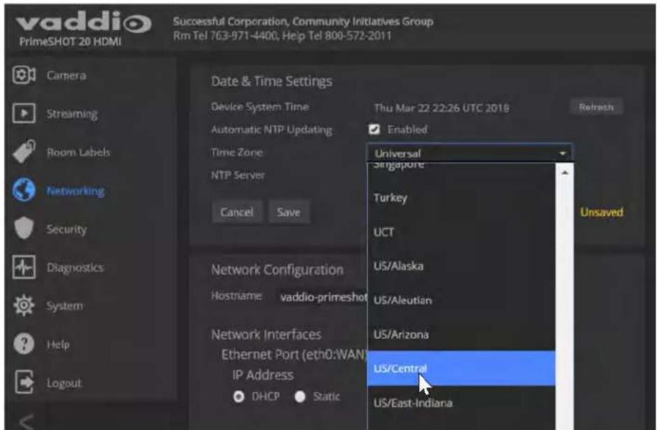
Setting Time Zone and NTP Server
NETWORKING PAGE
Using automatic NTP updating ensures that the timestamps in the camera's diagnostic log are accurate. Specifying your time zone may make it easier to match logged events with other actions and external events.
- To make the time zone and NTP server editable, enable Automatic NTP Updating.
- Select the desired time zone from the list.
- If desired, specify the NTP server to use. If you are not sure about this, use the default.
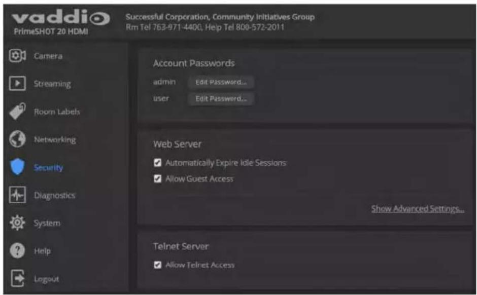
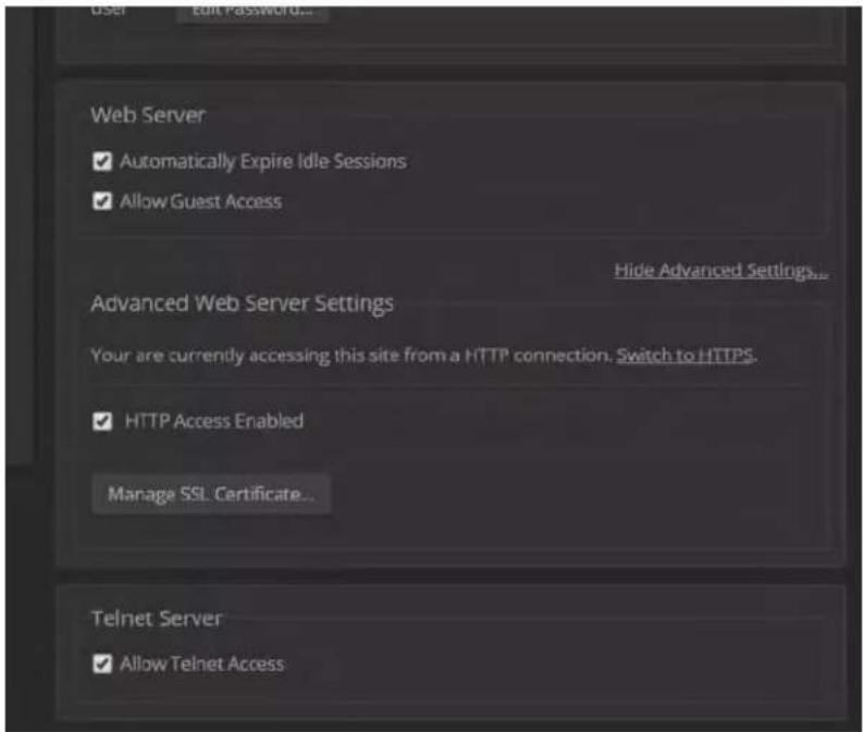
Managing Access and Passwords
SECURITY PAGE
Things you can do on this page:
- Allow people to access the Controls screen without logging on (Allow Guest Access) – this is enabled by default
- Set whether inactive sessions log off automatically or not (Automatically Expire Idle Sessions) – by default, inactive sessions expire after 30 minutes
■ Change the password for the admin account (default is password)
■ Change the password for the user account (default is password)
■ Disable Telnet access
The Security page also provides advanced settings for web access, to configure the camera to comply with your organization's network security policies.
Note
For best security, Vaddio strongly recommends changing the user and admin passwords. Using the default passwords leaves the product vulnerable to tampering. Be sure you have a way to find the passwords after changing them.
Advanced settings include:
■ Use HTTPS connection/Use HTTP connection
■ HTTP Access Enabled (selected by default)
■ Manage SSL Certificate
Note
Consult your IT department before disabling Telnet access or making any changes to the Advance settings.
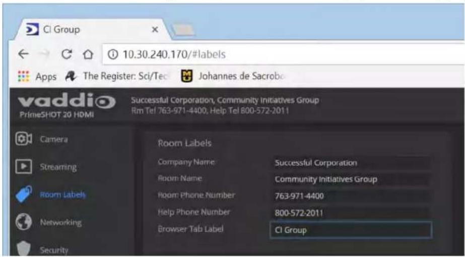
Adding Room Information to the Screen
ROOM LABELS PAGE
Enter your organization's name, the conference room name and phone number, and the number for people to call for in-house A/V support. This information is displayed on every page of the web interface.
Rebooting the Camera
SYSTEM PAGE, FIRMWARE TAB
This can help if the camera stops responding as you expect. In the System Utilities section, select Reboot.
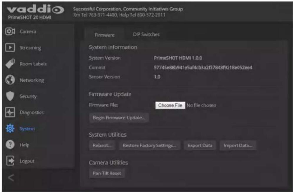
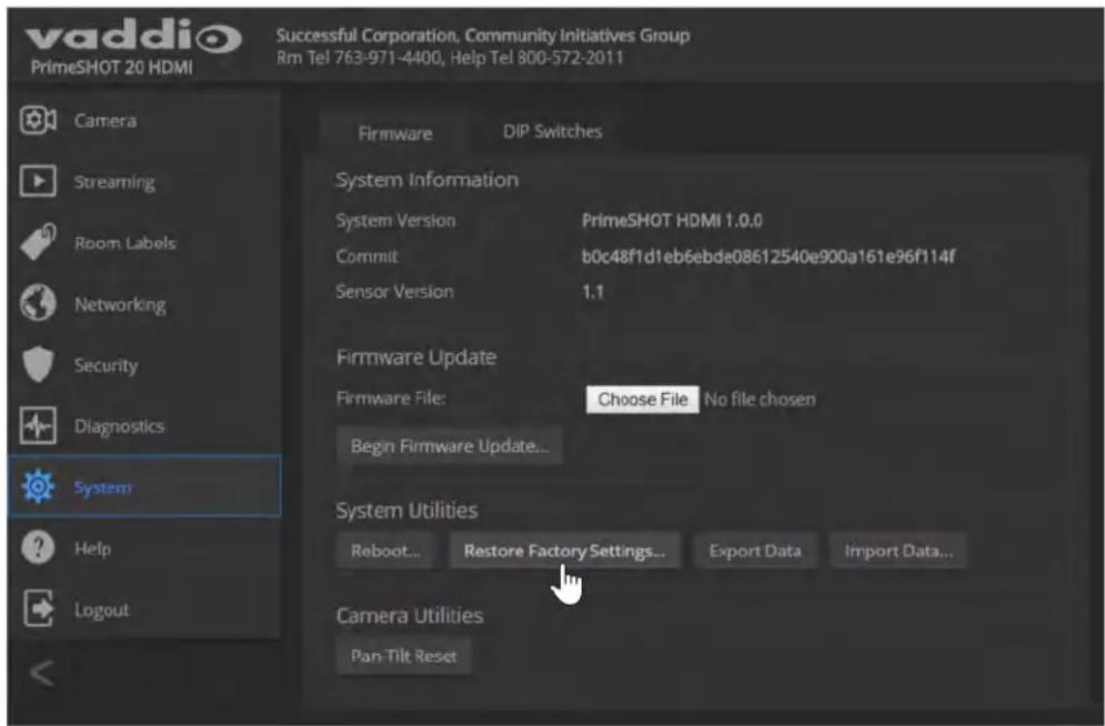
Saving or Restoring a Configuration
SYSTEM PAGE, FIRMWARE TAB
If you need to configure several cameras the same way, you can configure the first one, export its configuration, and then import the configuration to the other cameras. The export downloads to your computer as a .dat file. The filename is the camera's hostname.
Note
If the camera is using an older software version, it may be unable import a configuration that from a camera using a different version of software.
Starting a Firmware Update
SYSTEM PAGE, FIRMWARE TAB
-
Be sure you have downloaded the appropriate update file to your computer.
-
Select Choose File. In the box that opens, select the update file.
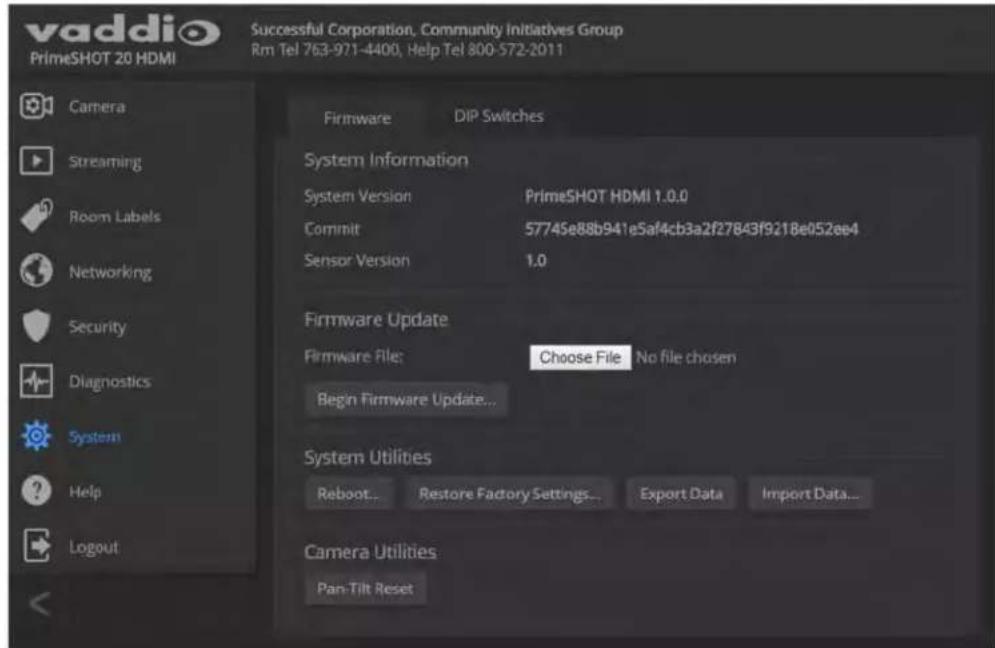
-
Select Begin Firmware Update.
-
READ the information in the Confirm dialog box and be sure you understand it. It may seem boring, but it could save you some time and aggravation.
-
When you are ready to start the update, select Continue. A progress message box opens and the indicator light on the front of the camera turns yellow to show the firmware update is in progress. If the update process presents warnings or error messages, read them carefully.
The camera reboots when the update is complete.
- Contact Vaddio Technical Support if you encounter any problems with the update.
Caution
Do not remove power or reset the camera while the indicator is yellow, showing a firmware upa progress. Interrupting a firmware update can make the camera unusable.
Contacting Vaddio Technical Support
HELP PAGE
If you can't resolve an issue using your troubleshooting skills (or the Troubleshooting table in this manual), we are here to help.
You'll find information for contacting Vaddio Technical Support on the Help screen.

Viewing Diagnostic Logs
DIAGNOSTICS PAGE
If you encounter a problem that you can't solve, your Vaddio technical support representative may ask you to download and email the log file available from the Diagnostics screen.
![vaddio PrimeSHOT 20 HDMI Successful Corporation, Community Initiatives Group Rm Tel 763-971-4400, Help Tel 800-572-2011 Camera Streaming Room Labels Networking Security Diagnostics System Help Logput Diagnostics May 18:18:39:01 vaddio-corvus [0.890740] sdcti-pittal: SOKT platform and DP driver helper May 18:18:39:01 vaddio-corvus [0.905570] mxc0: no vmmc regulator found May 18:18:39:01 vaddio-corvus [0.909567] mxc0: no vmmc regulator found May 18:18:39:01 vaddio-corvus [0.953697] mxc0: SOKT controller on w0100000.ps7-sdiq [w0100000.ps7-sdiq] using AOKI May 18:18:39:01 vaddio-corvus [0.967447] ledrig-cpu, registered to indicate activity on CPUs May 18:18:39:01 vaddio-corvus [0.966663] nf contrack version U.S.D (DDI2 buckets, 24048 max) May 18:18:39:01 vaddio-corvus [0.953110] ip_tables: (C) 2000-2006 NetFilter Core Team May 18:18:39:01 vaddio-corvus [0.998431] TCP: cubic registered May 18:18:39:01 vaddio-corvus [1.001661] Initializing XFERA netlink socket May 18:18:39:01 vaddio-corvus [1.005954] HFT: Registered protocol family 37 May 18:18:39:01 vaddio-corvus [1.018356] HDTQ: HDT-IO ViAN Support v1.8 May 18:18:39:01 vaddio-corvus [1.014707] Registering SNP/SNPR emulation handler May 18:18:39:01 vaddio-corvus [1.026265] regulator-dummy: disabling May 18:18:39:01 vaddio-corvus [1.028873] ALSA device list: May 18:18:39:01 vaddio-corvus [1.031839] No soundcards found. May 18:18:39:01 vaddio-corvus [1.035273] mxc0: new high speed SD card at address b368 May 18:18:39:01 vaddio-corvus [1.041283] mcbikb: mwc@b368 AF ID 4/7 PMB May 18:18:39:01 vaddio-corvus [1.054966] mmcikb: p1 p2 p3 p4 < p5 p6 p7 p8 > May 18:18:39:01 vaddio-corvus [1.062149] VFS: Mounted root (extA filesystem) readonly on device i79-2. May 18:18:39:01 vaddio-corvus [1.071853] devtmpfs: mounted May 18:18:39:01 vaddio-corvus [1.074926] Freezing unused kernel memory: 16K (cBA4400 - cBA5e900) May 18:18:39:01 vaddio-corvus [1.941390] lirc_gpio lirc_gpio@ lirc_dev: driver lirc_gain registered at minon = 0 May 18:18:39:01 vaddio-corvus [1.940775] lirc_gpio: driver registered! May 18:18:39:01 vaddio-corvus [1.955134] lirc_gpio: using active low receiver on GPIO pin 75 May 18:18:39:01 vaddio-corvus [3.077675] random: dd urandou read with S4 bits of entropy available May 18:18:39:01 vaddio-corvus [7.000610] random: nonblocking pool is initialized May 18:18:39:08 vaddio-corvus [11.55A399] scomacs.e00B-400.ps7-ethernet: Set clk = D-IO May 18:18:39:08 vaddio-corvus [11.55B47] scomacs.e00B-400.ps7-ethernet: link up (TBB/FARL) Download Refresh Clear Restore Auto-Refresh](/content/2026/06/1206021/images/4a0084695215a897c311ec3739310d674356b5eeb7dfddfa17c580094d41cb01.jpg)
Configuring Camera Behavior
Basic camera configuration tasks are available on the Camera page:
■ Set a custom Home position and other presets
■ Adjust for the lighting in the room
■ Set pan, tilt, and zoom speeds
Other camera configuration tasks are available on these pages:
■ Streaming – IP streaming settings
■ System (DIP Switches tab) – How the camera responds to the remote, status light behavior, image flip, and other settings
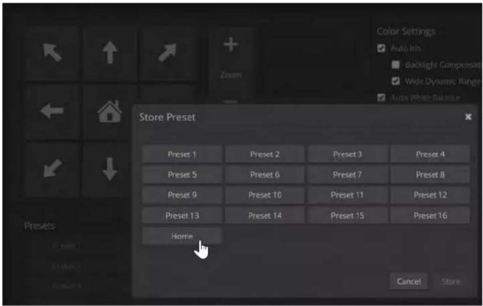
Storing Preset Positions Including Custom Home
- Set up the camera shot, then use the Store button to open the Store Preset box.
- Select one of the preset buttons - either a numbered preset or the Home button.
- To save the current CCU settings along with the camera position, check Store with Current Color Settings.
- Store the preset.
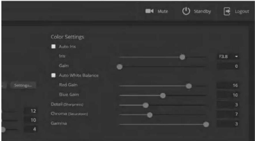
Adjusting the Color Settings
Fine-tune the color and lighting as needed using the Color Settings controls.
■ Auto Iris allows the camera to compensate automatically for the light level. Clear this box to adjust iris and gain manually.
■ Backlight Compensation (available with Auto Iris) reduces contrast to adjust for bright light behind the main subject of the shot. This setting can't be used with Wide Dynamic Range.
- Wide Dynamic Range (available with Auto Iris) increases the contrast between the brightest and darkest areas. This setting can't be used with Backlight Compensation.
■ Auto White Balance adjusts color automatically. Clear this box to adjust red gain and blue gain manually.
■ Red Gain and Blue Gain (available when Auto White Balance is not selected) provide manual color adjustment.
■ Detail adjusts the image sharpness. If the video looks grainy or "noisy," try a lower Detail setting.
■ Chroma adjusts the color intensity.
■ Gamma adjusts the range between bright areas and shadows.
If you make a change that you don't like, start over by selecting and then deselecting Auto White Balance.
Adjusting the Focus
Open the Focus control to select Auto-focus, or to set manual focus with the + (near) and - (far) buttons.
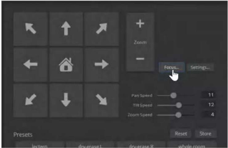
Setting the Speeds of Camera Movements
To set speeds for movements to presets:
In the Global Preset Speeds section, set the speeds for movements to presets.
To set speeds for movements using the arrow buttons:
Use the speed sliders to adjust the speed of movements that you control with the buttons for pan, tilt, and zoom. For tight shots, slower is usually better.
Setting Pan Direction
By default, the arrow buttons move the camera in the direction that viewers at the far end would see. If you face the camera and use the left arrow button, the camera pans to your right.
To switch the camera pan direction to the near end point of view, use the Settings button to open the pan and tilt direction box. Then set Pan Direction to Inverted.
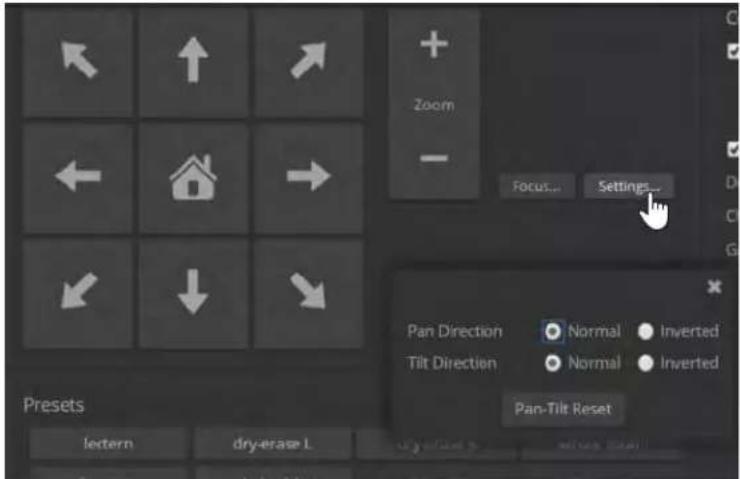
Note
To change tilt direction, please use the soft DIP switch on the System page.
Enabling or Disabling Streaming
STREAMING PAGE
IP streaming is enabled by default. Clear the Enable IP Streaming checkbox to change this.
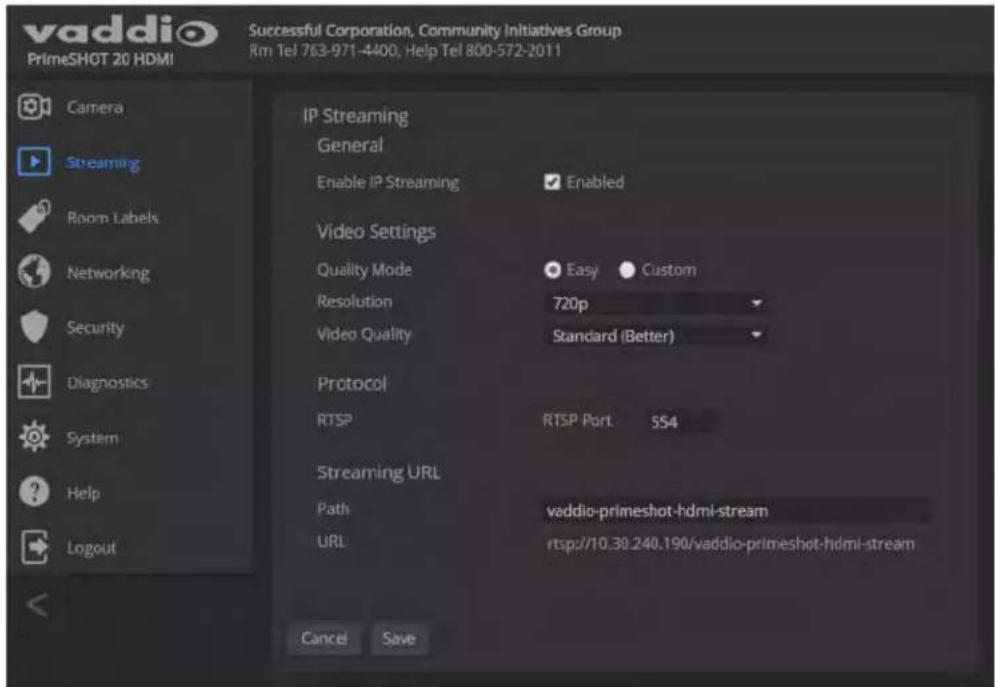
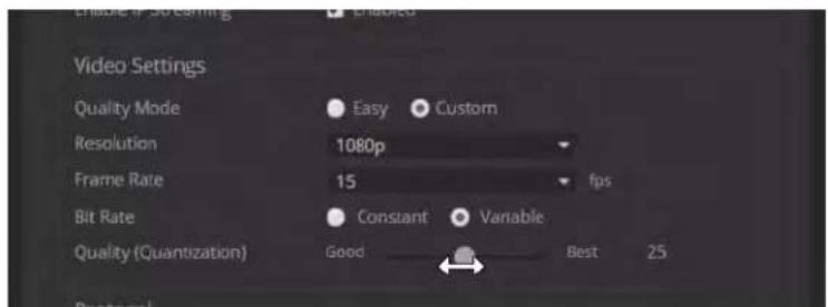
Configuring IP Streaming
STREAMING PAGE
Note
The web interface presents all the possible streaming resolutions values, but the IP stream cannot higher than the value set with the video resolution switch on the back of the camera. (See Video Resolution for information on setting the switch.) If the selected value is out of range, the camera will adjust the streaming resolution.
If you are not sure about these settings, start with the defaults.
-
Select the video Quality Mode: Easy or Custom. Easy takes care of most settings automatically; Custom provides additional control.
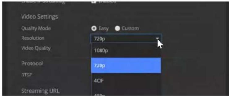
-
Select the desired IP streaming resolution.
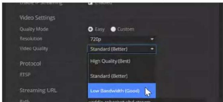
- Easy quality mode only: Select Video Quality.
- Custom quality mode only: Select the desired IP streaming frame rate.
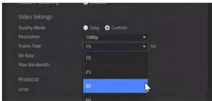
-
Custom quality mode only: Select Constant or Variable Bit Rate.
-
Custom quality mode, Constant Bit Rate only: Set Max Bandwidth.
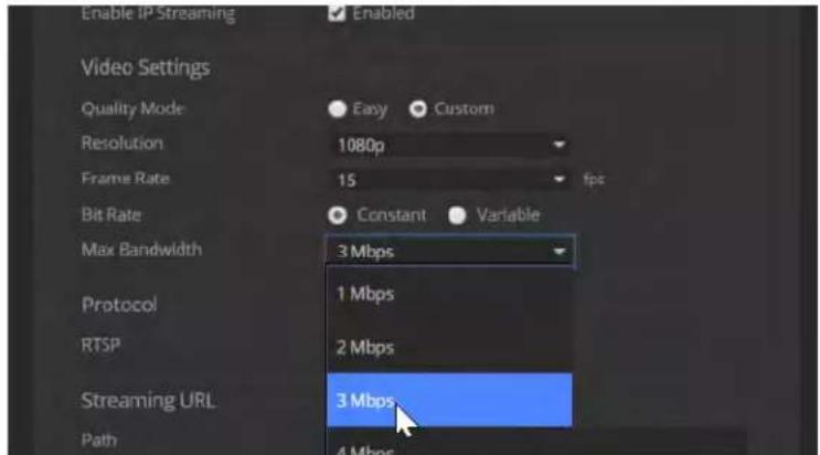
- Custom quality mode, Variable bit rate only: Set the Quality (Quantization) slider.
Advanced IP Streaming Settings
Consult your IT department before changing these.
RTSP port: Vaddio strongly recommends using the default RTSP port number unless you need to change it. Consult your IT department.
Streaming URL: Edit the path to change the portion of the streaming URL that appears after the IP address, if necessary.
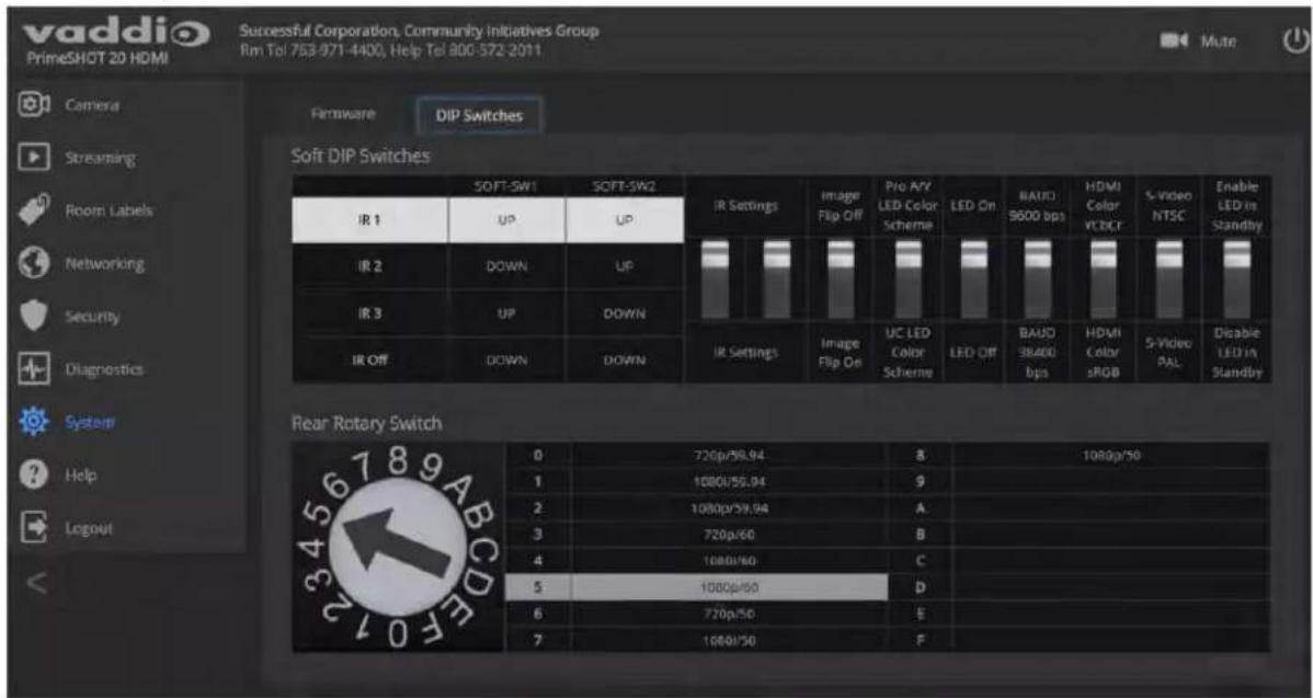
Setting Other Camera Behaviors
SYSTEM PAGE, DIP SWITCHES TAB
The DIP Switches tab of the System page provides access to these features via soft switches:
Camera ID (IR Settings) – The IR Remote Commander can control up to three cameras in the same room with different IR frequencies. Use IR Settings switches 1 and 2 to select the frequency to identify the camera as camera 1, 2, or 3; then use the Camera Select buttons at the top of the remote to select the camera you want to control.
Image Flip - If mounting the camera upside-down, set IMAGE FLIP ON.
Baud Rate (9600 bps or 38400 bps) - RS-232 serial communication rate.
HDMI color - YCbCr (default) or sRGB.
LED color scheme – Status light color codes for Pro AV (broadcast) or UC (unified conferencing); set to Pro AV by default, to follow the standard for broadcast cameras. At this time, the two color schemes are functionally identical on this camera.
LED on/off – In most cases, Vaddio recommends leaving the status light on, to let people in the room know whether the camera is currently sending video.
S-Video NTSC/PAL - US (NTSC) or European (PAL) format.
Enable/Disable LED in Standby Mode – If the LED is enabled in standby (low-power) mode, it illuminates purple when the camera is in standby mode. If the LED is disabled, it turns off when the camera is in standby mode.
Note
By default, the camera's status light is active during normal operation; however, it can be configured to remain off when the camera is powered up. The camera may be sending video even if the inc off.
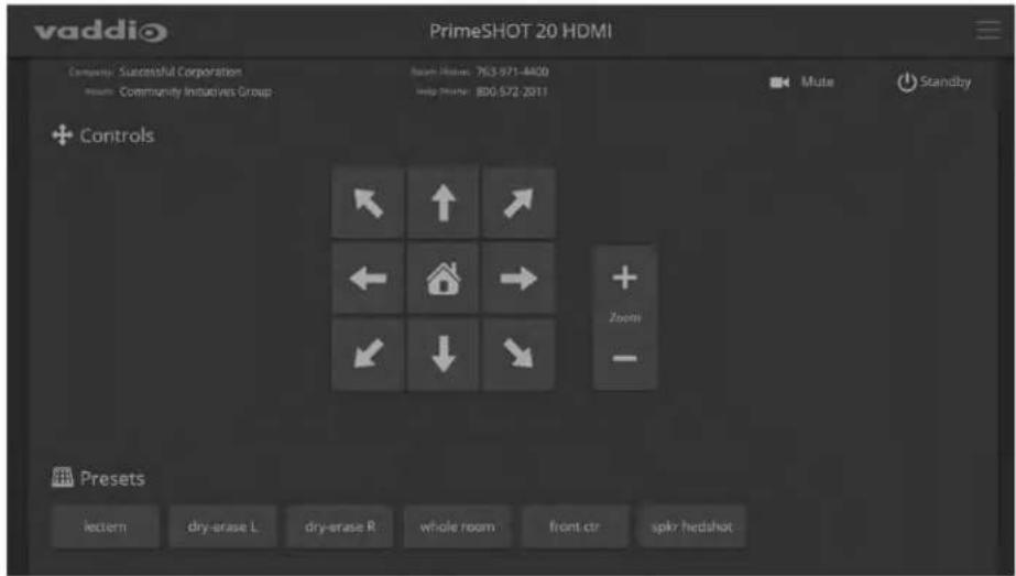
Operating the Camera
CONTROLS PAGE (USER OR GUEST ACCESS)
The Controls page provides most of the same controls as the IR Remote Commander:
■ Pan, tilt, zoom, or return to home position
■ Stop or resume transmitting live camera video (video mute)
■ Put the camera in standby or bring it back to the ready state
■ Move to camera presets, if any have been stored
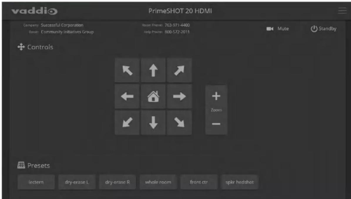
Moving the Camera
Use the arrow buttons for camera pan and tilt. The center button moves the camera to the home position.
Zooming In or Out
Use the Zoom + button to zoom in and the Zoom - button to zoom out.
Moving the Camera to a Preset Position
Use the Preset buttons (if available) to move the camera to any of its programmed positions. Presets are only available if they have been set in the administrative interface.
Stopping or Resuming Video
Use the Mute button to temporarily stop video from the camera without placing it in standby. Remember that the mute button does not mute the room's microphones. In video mute mode, the camera transmits blue or black video, with a message that the video is muted.
Managing the Camera Ready State
Use the Standby button to switch between low-power (standby) and ready states.
Telnet Serial Command API
The Vaddio Telnet command API allows an external device such as an AMX or Crestron presentation system to control the camera.
Note
When you connect via Telnet, you must log in using the account.
The command format follows a get/set structure. Here are some examples:
| Command | camera pan right |
| Response | OK> |
| Command | camera focus mode auto |
| Response | OK> |
| Command | camera ccu get iris |
| Response | iris 6OK> |
Use a question mark as a command parameter to bring up a list of commands, subcommands, or command parameters. For example:
> camera focus ?
near Focus the camera near far Focus the camera far stop Stop the camera focus mode Camera focus mode
Things you might need to know about control via Telnet session:
■ Command lines are terminated with a carriage return.
■ All ASCII characters (including carriage returns) are echoed to the terminal program and appended with the VT100 string ESC[J (hex 1B 5B 4A), which most terminal programs automatically strip.
■ CTRL-5 Clears the current serial buffer on the device.
Typographical conventions:
■ n {x | y | z} - Choose x, y, or z.
■ n
■ n < x - y > - Valid range of values is from x through y.
■ n [optional] - Parameter is not required.
camera home
| Synopsis camera | home |
| Example | >camera homeOK> |
camera pan
Moves the camera horizontally
| Synopsis camera | pan { left [] | right [] | stop | get | set[] } | |
| Options | left | Moves the camera left. |
| right | Moves the camera right. | |
| speed <1 - 24> Optional: Specifies the pan speed as an integer(1 to 24). Default speed is 12. | ||
| stop | Stops the camera's horizontal movement. | |
| setSets the camera's absolute pan position indegrees, as a floating point value betweenapproximately -160.00 and 160.00.This is the minimum range. Individual camerasmay have slightly more travel before they reachtheir physical limits. | ||
| get Returns the camera's absolute pan position indegrees, as a floating point value betweenapproximately -160.00 (left) and 160.00 (right). | ||
| Examples | >camera pan leftOK>Pans the camera left at the default speed.>camera pan right 20OK>Pans the camera right using a speed of 20.>camera pan stopOK>Stops the camera's horizontal motion. | |
camera tilt
Moves the camera vertically.
| Synopsis camera | tilt{ up [] | down [] | stop | get | set[] } | |
| Options | up | Moves the camera up. |
| down | Moves the camera down. | |
| speed <1 - 20> Optional: Specifies the tilt speed as an integer (1 to 20). Default speed is 10. | ||
| stop | Stops the camera's vertical movement. | |
| setSets the camera's absolute tilt position in degrees, as a floating point value between approximately -30.00 and 90.00. This is the minimum range; individual cameras may have an additional degree or two of travel before they reach their physical limits. | ||
| get Returns the camera's absolute tilt position in degrees, as a floating point value between approximately -30.00 (down) and 90.00 (up). | ||
| Examples | >camera tilt upOK>Tilts the camera up at the default speed.>camera tilt down 20OK>Tilts the camera down at a speed of 20.>camera tilt 15.25 12OK>Tilts the camera to position 15.25 at a speed of 12. | |
camera zoom
Moves the camera in toward the subject or out away from the subject.
| Synopsis camera | zoom { in [] | out [] | stop | get | set} | |
| Options | in | Zooms the camera in. |
| out | Zooms the camera out. | |
| stop | Stops the camera's zoom movement. | |
| setSets the camera's | zoom level as a floating point value between 1 and 20. | |
| getReturns the camera's zoom setting as a floating point value between 1 and 20. | ||
| Examples | >camera zoom inOK>camera zoom stopOK>Stops the camera's zoom motion. | |
camera focus
Changes the camera focus.
| Synopsis camera | focus { near [] | far [] stop | mode {get | auto | manual} } | |
| Options | near | Brings the focus nearer to the camera. Can only be used when camera is in manual mode. |
| far | Moves the focus farther from the camera. Can only be used when camera is in manual mode. | |
| speed <1 - 8> Optional: integer | (1 to 8) specifies the focus speed. | |
| mode [get | auto | manual] | Returns the current focus mode, or specifies automatic or manual focus. | |
| stop | Stops the camera's focus movement. | |
Examples | camera focus nearOK>Brings the focus near at the default speed.camera focus far 7OK>Moves the focus farther from the camera at a speed of 7.camera focus mode getauto_focus: onOK>Returns the current focus mode. | |
camera preset
Moves the camera to the specified preset, or stores the current camera position and optionally CCU information.
| Synopsis camera | preset { recall | store} [1 - 16] [save-ccu] | |
| Options recall | [1 - 16] Moves the camera to the specified preset. | |
| store [1 - 16] Stores the current camera position as the specified preset. | ||
| save-ccu | Optional: Saves the current CCU (color and lighting) settings as part of the preset. If no specified, the last color settings are used w recalled. | |
| Examples | >camera preset recall 3OK>Moves the camera to preset 3.>camera preset store 1OK>Saves the camera's current position as preset 1. | |
camera ccu get
Returns CCU (lighting and color) information.
| Synopsis camera | ccu get | |
Options | auto_white_balance | Returns the current state of the auto white balance setting (on or off). |
| red_gain | Returns the red gain value as an integer (0 to 20). | |
| blue_gain | Returns the blue gain value as an integer (0 to 20). | |
| backlight_compensation | Returns the current state of the backlight compensation setting (on or off). | |
| iris | Returns the iris value as an integer (0 to 11). | |
| auto_iris | Returns the current auto-iris state (on or off). | |
| gain | Returns the gain value as an integer (1 to 10). | |
| detail | Returns the detail value as an integer (0 to 10). | |
| chroma | Returns the chroma value as an integer (0 to 20). | |
| wide_dynamic_range | Returns the current setting for Wide Dynamic Range (on or off). | |
| all | Returns all current CCU settings. | |
| Examples | >camera ccu get irisiris 6OK>Returns the current iris value.>camera ccu get red_gainred_gain 201OK>Returns the current red gain value.>camera ccu get allauto_iris onauto_white_balance onbacklight_compensation offblue_gain 10chroma 7detail 3gain 2iris 9red_gain 10wide_dynamic_range onOK>Returns all current CCU settings. | |
camera ccu set
Sets the specified CCU (lighting) information.
| Synopsis camera | ccu set | |
Options auto_white | te_balance {on | off} Sets the | current state of the auto white balance setting (on or off). Auto white balance overrides red gain and blue gain manual settings. |
| red_gain <0 - 20> Sets the red gain value as an integer (0 to 20). Can only be used when auto white balance is off. | ||
| blue_gain <0 - 20> Sets the blue gain value as an integer (0 to 20). Can only be used when auto white balance is off. | ||
| backlight_compensation {on | off} | Sets the current state of the backlight compensation setting (on or off). Can only be used when wide dynamic range mode is off. | |
| iris <0 - 11> Sets the iris value as an integer (0 to 11). Can only be used when auto-iris is off. | ||
| auto_iris {on | off} Sets the auto-iris state (on or off). Auto-iris disables manual iris and gain when it is on. | ||
| gain <1 - 10> Sets gain value as an integer (1 to 10). Can only be used when auto-iris is off. | ||
| detail <0 - 10> Sets the detail value as an integer (0 to 10). | ||
| chroma <0 - 20> Sets the chroma value as an integer (0 to 20). | ||
| wide_dynamic_range {on | off} Sets Wide Dynamic Range mode on or off. Can only be used when backlight compensation is off. | ||
| Examples | >camera ccu set auto_iris offOK>Turns off auto-iris mode, returning the camera to manual iris control.>camera ccu set red_gain 10OK>Sets the red gain value to 10. | |
camera ccu scene
Stores the current CCU scene or recalls the specified ccu scene.
| Synopsis camera | ccu scene {recall {factory <1 - 6> | custom <1 - 3>} | store custom <1 - 3>} | |
| Options recall | factory <1 - 6>recall custom <1 - 3> | Recalls the camera to the specified scene (factory 1 - 6 or custom 1 - 3). |
| store custom <1 - 3> Saves | the current scene as the specified custom scene. | |
| Examples | >camera ccu scene recall factory 2OK>Sets the camera to use factory CCU scene 2.>camera ccu scene store custom 1OK>Saves the current CCU scene as custom CCU scene 1. | |
camera led
Set or change the behavior of the indicator light.
| Synopsis camera | led {get | off | on} | |
| Options | get | Returns the indicator light's current state (on or off). |
| off | Disables the indicator light. | |
| on | Enables the indicator light. | |
| Examples | >camera led offOK>Disables the indicator light. You cannot tell by looking at the camera whether it is sending video.>camera led getled: onOK>Returns the current state of the indicator light. | |
camera recalibrate
Recalibrates the pan and tilt motors. This is typically done in response to a motor fault indication or error message.
| Synopsis camera | recalibrate |
| Example | >camera recalibrateOK> |
camera standby
Set or change camera standby status.
| Synopsis camera | standby {get | off | on | toggle} | |
| Options | get | Returns the camera's current standby state. |
| off | Brings the camera out of standby (sleep) mode. | |
| on | Stops video and puts the camera in standby mode. | |
| toggle | Changes the camera's standby state - if it was not in standby mode, it enters standby; if it was in standby mode, it "wakes up." | |
| Examples | >camera standby offOK>Brings the camera out of standby mode.>camera standby get standby: onOK>Returns the current standby state. | |
video mute
Gets or sets the camera's video mute status. When video is muted, the camera sends blue or black video with an on-screen message stating that video mute is on. This can be desirable when preparing the room, or when privacy is needed.
Note
In systems with audio, this command does not affect the audio.
| Synopsis video mute {get | off | on | toggle} | ||
| Options | get | Returns the current video mute status. |
| off | Unmutes the video. (Normal video resumes.) | |
| on | Mutes the video. (Blue or black screen with message) | |
| toggle | Changes the camera's video mute status. | |
| Examples | >video mute getmute: offOK>Returns video mute status.>video mute onOK>Transmits blue or black video. | |
streaming settings get
Retrieves IP streaming settings. These are configured in the web interface.
| Synopsis streaming settings get | ||
| Parameters | IP Custom_Frame_Rate | Frame rate selected in Custom quality mode. |
| IP Custom_Resolution | Resolution selected in Custom quality mode. | |
| IP Enabled | True if IP streaming is enabled, False if it is not. | |
| IP Port | The RTSP port number used for IP streaming. Default is 554. | |
| IP Preset_Quality | Video quality selected in Easy video quality mode. | |
| IP Preset_Resolution | Resolution selected in Easy video quality mode. | |
| IP Protocol | The IP streaming protocol in use. | |
| IP URL | The URL where the stream is available. | |
| IP Video_Mode | Video quality mode selected (preset or custom) | |
| Example | >streaming settings getIP Custom_Frame_Rate 15IP Custom_Resolution 1080pIP Enabled trueIP Port 554IP Preset_Quality Standard (Better)IP Preset_Resolution 720pIP Protocol RTSPIP URL vaddio-primeshot-hdmi-streamIP Video_Mode presetOK>Returns the current streaming settings. | |
network settings get
Returns the camera's current network settings and MAC address.
| Synopsis | network settings get |
| Example | network settings getName eth0:WANMAC Address 00:1E:C0:F6:CA:7BIP Address 192.168.1.67Netmask 255.255.255.0VLAN DisabledGateway 192.168.1.254OK> |
network ping
Sends an ICMP ECHO_REQUEST to the specified IP address.
| Synopsis network | ping [count] [size] | |
| Options | The number of ECHO_REQUEST | packets to send. Default is five packets. |
| The size of each ECHO_ | REQUEST packet. Default is 56 bytes. | |
| The IP address | where the ECHO_REQUEST packets will be sent. | |
| Examples | >network ping 192.168.1.66PING 192.168.1.66 (192.168.1.66): 56 data bytes64 bytes from 192.168.1.66: seq=0 ttl=64 time=0.476 ms64 bytes from 192.168.1.66: seq=1 ttl=64 time=0.416 ms64 bytes from 192.168.1.66: seq=2 ttl=64 time=0.410 ms64 bytes from 192.168.1.66: seq=3 ttl=64 time=0.410 ms64 bytes from 192.168.1.66: seq=4 ttl=64 time=3.112 ms--- 192.168.1.66 ping statistics ---5 packets transmitted, 5 packets received, 0% packet lossround-trip min/avg/max = 0.410/0.964/3.112 ms>Sends five ECHO_REQUEST packets of 56 bytes each to the host at 192.168.1.66. | |
| >network ping count 10 size 100 192.168.1.1Sends 10 ECHO_REQUEST packets of 100 bytes each to the host at 192.168.1.1.The command returns data in the same form as above. | ||
system reboot
Reboots the system either immediately or after the specified delay. Note that a reboot is required when resetting the system to factory defaults (system factory-reset).
| Synopsis system | reboot [] | |
| Options | The number of seconds to delay the reboot. | |
system factory-reset
Gets or sets the factory reset status. When the factory reset status is on, the system resets to factory defaults on reboot.
| Synopsis system | factory-reset {get | on | off} | |
| Options | get | Returns the camera's current factory reset status. |
| on | Enables factory reset on reboot and returns he camera's current factory reset status. | |
| off | Disables factory reset on reboot and returns he camera's current factory reset status. | |
| Examples | >system factory-reset getfactory-reset (software): offfactory-reset (hardware): offOK>Returns the factory reset status.This evaluates the most recent system factory-reset on or off command, if one has been received, then reads the rear panel rotary switchand returns the status on if it is in the D position.>system factory-reset onfactory-reset (software): onfactory-reset (hardware): offOK>Enables factory reset upon reboot.NoteThis command does not initiate a factory reset. The factory reset takes place on next reboot. | |
version
Returns the current firmware version.
| Synopsis version | |
| Example | >versionCommit b0c31c48ff4f1d128ceb6cf7ebd0c2861cf440edSensor Version 1.1System Version PrimeSHOT HDMI 1.0.0OK> |
help
Displays an overview of the CLI syntax.
| Synopsis help | |
Example | help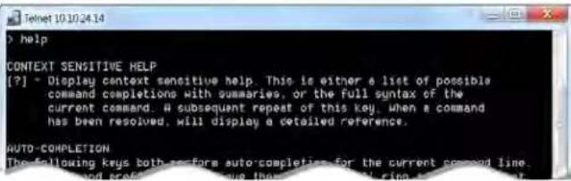 |
history
Returns the most recently issued commands from the current Telnet session. Since many of the programs read user input a line at a time, the command history is used to keep track of these lines and recall historic information.
| Synopsis history | ||
| OptionsInteger value specifying the maximum number of commands to return. | ||
| Examples | historyDisplays the current command buffer.history 5Sets the history command buffer to remember the last 5 unique entries. | |
Additional information | You can navigate the command history using the up and down arrow keysThis command supports the expansion functionality from which previous commands can be recalled from within a single session. History expansion performed immediately after a complete line is read.Examples of history expansion:* !! Substitute the last command line.* !4 Substitute the 4th command line (absolute as per 'history' command* !-3 Substitute the command line entered 3 lines before (relative) | |
exit
Ends the command session and closes the socket.
| Synopsis exit | |
| Example | exit |
RS-232 Control
The Vaddio Control Protocol is similar to the ^® VISCA command set in order to be compatible with several popular control devices. Not all VISCA commands are supported and there are Vaddio-specific commands in the following command and inquiry lists.
For RS-232 communication settings and connector pin-out, see RS-232 Serial Communication.
Camera Movement, Zoom, and Focus Commands
| Command Set | Command Command Packet Comments | |
| CAM_Zoom Stop | 8x 01 04 07 00 FF Variable speed: p = 0 (low) to 7(high)Tele (std) 8x 01 04 07 02 FFWide (std) 8x 01 04 07 03 FFTele (variable) 8x 01 04 07 2p FFWide (variable) 8x 01 04 07 3p FFDirect 8x 01 04 47 0p 0q 0r 0s FFCorresponds to camera zoom in Telnet API | |
| CAM_Focus | Stop 8x 01 04 08 00 FF Variable speed: p = 0 (low) to 7(high)Far (std) 8x 01 04 08 02 FFNear (std) 8x 01 04 08 03 FFFar (variable) 8x 01 04 08 2p FFNear (variable) 8x 01 04 08 3p FFDirect 8x 01 04 48 0p 0q 0r 0s FFAuto Focus 8x 01 04 38 02 FFManual Focus 8x 01 04 38 03 FFAuto/Manual 8x 01 04 08 10 FFOne Push Trigger 8x 01 04 18 01 FFNear Limit 8x 01 04 28 0p 0q 0r 0s FFCorresponds to camera focus in Telnet API | |
| Pan-TiltDrive Up | 8x 01 06 01 vv ww 03 01 FF vv= Pan speed (01h-18h) | ww=Tilt speed (01h-14h) |
| Down 8x 01 06 01 vv ww 03 02 FF | ||
| Left 8x 01 06 01 vv ww 01 03 FF | ||
| Right 8x 01 06 01 vv ww 02 03 FF | ||
| UpLeft 8x 01 06 01 vv ww 01 01 FF | ||
| UpRight 8x 01 06 01 vv ww 02 01 FF | ||
| DownLeft 8x 01 06 01 vv ww 01 02 FF | ||
| DownRight 8x 01 06 01 vv ww 02 02 FF | ||
| Stop 8x 01 06 01 vv ww 03 03 FF | ||
| Absolute Position 8x 01 06 02 vv ww 0Y 0Y 0Y 0Y 0Y0Y0Y0Y = Pan position (90E2h-6BD8h)0Z0Z0Z0Z = Tilt position (EB99h-3D59h) | ||
| Home 8x 01 06 04 FF | Returns the camera to its default position | |
| Pan-TiltDrive | Reset 81 01 06 05 FF | Resets/recalibrates the pan and tilt motors |
| Corresponds to camera recalibrate in Telnet API | ||
| Pan-Tilt-ZoomDrive | Up 8x 01 06 0A vv ww rr 03 01 03 FF | vv= Pan speed (01h-18h)ww=Tilt speed (01h-14h)rr=Zoom speed (00h - 07h) |
| Down 8x 01 06 0A vv ww rr 03 02 03 FF | ||
| Left 8x 01 06 0A vv ww rr 01 03 03 FF | ||
| Right 8x 01 06 0A vv ww rr 02 03 03 FF | ||
| In 8x 01 06 0A vv ww rr 03 03 | 01 FF | |
| Out 8x 01 06 0A vv ww rr 03 03 | 02 FF | |
| Stop 8x 01 06 0A vv ww rr 03 03 | 03 FF | |
| Home 8x 01 06 0C FF | Returns the camera to the default position and zoom | |
| Pan-Tilt-ZoomDrive | Absolute Position 8x 01 06 0B vv ww 0Y 0Y 0Y 0Y 0Y 0Y0Y0Y0Y = Pan position (90E2h-6BD8h)0Z0Z0Z0Z = Tilt position (EB99h-3D59h)0R0R0R0R = Zoom position (04000h) | |
| CAM_Memory Re | set 8x 01 04 3F 00 0p FF p= preset number(0h-0Fh) | |
| Set 8x 01 04 3F 01 0p FF | ||
| Set with 'scene' | 8x 01 04 3F 21 0p FF | |
| Recall 8x 01 04 3F 02 0p FF | ||
| Corresponds to camera preset in Telnet API. | ||
Movement, Zoom, and Focus Inquiry Commands
| Inquiry Command Command Response Packet | Comments | ||
| CAM_ZoomPosInq | 8x 09 04 47 FF | y0 50 0p 0q 0r 0s FF | pqrs: Zoom position |
| CAM_FocusPosInq | 8x 09 04 48 FF | y0 50 0p 0q 0r 0s FF | pqrs: Focus position |
| CAM_FocusModelInq | 8x 09 04 38 FF | y0 50 02 FF | Auto focus |
| y0 50 03 FF | Manual focus | ||
| Corresponds to camera focus mode get in Telnet API. | |||
| Pan-TiltPosInq | 8x 09 06 12 FF | y0 50 0w 0w 0w 0w 0z 0z FF | zw0zww= Pan positionzzzz=Tilt Position |
| CAM_MemoryInq | 8x 09 04 3F FF | y0 50 pp FF | pp: Preset number recalled last (00h - 0Fh) |
| CAM_MemoryStatusInq | 8x 09 04 3F 0p FF | y0 50 0p 0q 0r 0s FF | p: Preset number (00h - 0Fh)q: mode (00-std, 10-std /wccu)rs: speed (0x1-0x18) 1 - 24 |
| CAM_MemSavelInq | 8x 09 04 23 0X FF | y0 50 0p 0q 0r 0s FF | X: 00h to 0Fh (preset number)pqrs: 0000h to FFFFh (Data) |
| CAM_PTZ_PresetSpeedInq | 8x 09 7E 01 0B | FF y0 50 p q r FF | p:pan speed (01h-18h)q:tilt speed (01h-14h)r:zoom speed (0h-07h) |
Color and Light Management Commands
| Command Set | Command Command Packet Comments | |
| CAM_WB Auto 8x 01 04 35 00 | FF Normal auto | |
| Manual 8x 01 | 04 35 05 FF Manual control mode | |
| Corresponds to camera ccu set auto_white_balance in Telnet API. | ||
| CAM_RGain Reset 8x 01 04 03 | 00 FF Manual control of red gainpq = red gain (00h - 14h) | |
| Up | 8x 01 04 03 02 FF | |
| Down | 8x 01 04 03 03 FF | |
| Direct | 8x 01 04 43 00 00 0p 0q FF | |
| Corresponds to camera ccu set red_gain in Telnet API. | ||
| CAM_BGain | Reset 8x 01 04 04 00 FF Manual control of blue gainpq = blue gain (00h - 14h) | |
| Up | 8x 01 04 04 02 FF | |
| Down | 8x 01 04 04 03 FF | |
| Direct | 8x 01 04 44 00 00 0p 0q FF | |
| Corresponds to camera ccu set blue_gain in Telnet API. | ||
| CAM_AE | Auto 8x 01 04 39 00 FF Auto exposure mode | |
| Manual 8x 01 | 04 39 03 FF Manual control mode | |
| Corresponds to camera ccu set auto_iris in Telnet API. | ||
| CAM_Shutter | Reset 8x 01 04 0A 00 FF Shutter settingpq = shutter position (00h - 15h)SeeShutter Speed Values-CAM_Shutter Command | |
| Up | 8x 01 04 0A 02 FF | |
| Down | 8x 01 04 0A 03FF | |
| Direct | 8x 01 04 4A 00 00 0p 0q FF | |
| CAM_Iris | Reset 8x 01 04 0B 00 FF Irissettingpq = iris position(0h, 05h-11h)SeeIris Values - CAM_IrisCommand | |
| Up | 8x 01 04 0B 02 FF | |
| Down | 8x 01 04 0B 03 FF | |
| Direct | 8x 01 04 4B 00 00 0p 0q FF | |
| Corresponds to camera ccu set iris in Telnet API. | ||
| CAM_Gain | Reset 8x 01 04 0C 00 FF Irisgain settingpq = gain position (01h - 0Fh)p = gain limit (04h-0Fh)SeeIris Gain and Gain LimitValues - CAM_Gain Command | |
| Up | 8x 01 04 0C 02 FF | |
| Down | 8x 01 04 0C 03 FF | |
| Direct | 8x 01 04 4C 00 00 0p 0q FF | |
| +Gain Limit | 8x 01 04 2C 0p FF | |
| Corresponds to camera ccu set gain in Telnet API. | ||
| CAM_BackLight | On | 8x 01 04 33 02 FF Backlight compensation On/Off |
| Off | 8x 01 04 33 03 FF | |
| Corresponds to camera ccu set backlight_compensation in Telnet API. | ||
| Command Set | Command Com | mand Packet Comments | |
| CAM_WD On 8x | 01 04 3D 02 | FF Wide Dynamic Range On | |
| Off 8x 01 04 | 3D 03 FF Wide Dynamic Range Off | ||
| Corresponds to camera ccu set wide_dynamic_range in Telnet API. | |||
| CAM_Aperture Reset | 8x 01 04 | 02 00 FF Aperture setting | pq = aperture position (0h-0fh) |
| Up 8x 01 04 | 02 01 FF | ||
| Down | 8x 01 04 02 02 FF | ||
| Direct 8x 01 04 | 42 00 00 0p 0q FF | ||
| Corresponds to camera ccu set detail in Telnet API. | |||
| CAM_Chroma | Direct 8x 01 | 7E 55 00 00 0p 0q FF | pq: 00h - 14h |
| Corresponds to camera ccu set chroma in Telnet API. | |||
| CAM_Gamma | - | 8x 01 04 5B 0p FF | p = gamma setting (0: std,1: straight) |
| Corresponds to camera ccu set gamma in Telnet API. | |||
Shutter Speed Values (CAM_Shutter)
| Value 60/59.94/30/29.97 fps | 50/25 fps | ||
| 0x15 | 1/10000 | 1/10000 | |
| 0x14 | 1/6000 | 1/6000 | |
| 0x13 | 1/4000 | 1/3500 | |
| 0x12 | 1/3000 | 1/2500 | |
| 0x11 | 1/2000 | 1/1750 | |
| 0x10 | 1/1500 | 1/1250 | |
| 0x0F | 1/1000 | 1/1000 | |
| 0x0E | 1/725 | 1/600 | |
| 0x0D | 1/500 | 1/425 | |
| 0x0C | 1/350 | 1/300 | |
| 0x0B | 1/250 | 1/215 | |
| 0x0A | 1/180 | 1/150 | |
| 0x09 | 1/125 | 1/120 | |
| 0x08 | 1/100 | 1/100 | |
| 0x07 | 1/90 | 1/75 | |
| 0x06 | 1/60 | 1/50 | |
| 0x05 | 1/30 | 1/25 | |
| 0x04 | 1/15 | 1/12 | |
| 0x03 | 1/8 | 1/6 | |
| 0x02 | 1/4 | 1/3 | |
| 0x01 | 1/2 | 1/2 | |
| 0x00 | 1/1 | 1/1 | |
Iris Values (CAM_Iris)
| Value Iris | |
| 0x11 F1.6 | |
| 0x10 F2 | |
| 0x0F F2.4 | |
| 0x0E F2.8 | |
| 0x0D F3.4 | |
| 0x0C F4 | |
| 0x0B F4.8 | |
| 0x0A F5.6 | |
| 0x09 F6.8 | |
| 0x08 F8 | |
| 0x07 F9.6 | |
| 0x06 F11 | |
| 0x05 F14 | |
| 0x00 CLOSED |
Iris Gain and Gain Limit Values (CAM_Gain)
| Iris Gain Iris Gain Limit | |||||
| Value Steps Gain in dB | Value Steps Gain in dB | ||||
| 0x0F 28 77.8 | 0x0F | 28 77.8 | |||
| 0x0E 26 44.4 | 0x0E | 26 44.4 | |||
| 0x0D 24 41.0 | 0x0D | 24 41.0 | |||
| 0x0C 22 37.5 | 0x0C | 22 37.5 | |||
| 0x0B 20 34.1 | 0x0B | 20 34.1 | |||
| 0x0A 18 30.7 | 0x0A | 18 30.7 | |||
| 0x09 16 27.3 | 0x09 | 16 27.3 | |||
| 0x08 14 23.9 | 0x08 | 14 23.9 | |||
| 0x07 12 20.5 | 0x07 | 12 20.5 | |||
| 0x06 10 17.1 | 0x06 | 10 17.1 | |||
| 0x05 8 | 13.7 | 0x05 8 | 13.7 | ||
| 0x04 6 | 10.2 | 0x04 6 | 10.2 | ||
| 0x03 4 | 6.8 | ||||
| 0x02 2 | 3.4 | ||||
| 0x01 0 | 0 | ||||
Color and Light Management Inquiry Commands
| Inquiry Command Command Response | Packet Comments | ||
| CAM_WBModelnq 8x 09 | 04 35 FF y0 50 | 00 FF Auto | |
| y0 50 05 FF Manual | |||
| CAM_RGainlnq 8x 09 04 | 43 FF y0 50 00 | 00 0p 0q FF pq: Red | gain |
| CAM_BGainlnq 8x 09 04 | 44 FF y0 50 00 | 00 0p 0q FF pq: Blue | gain |
| CAM_AEModelnq 8x 09 | 04 39 FF y0 50 | 00 FF Auto | |
| y0 50 03 FF Manual | |||
| CAM_ShutterPoslnq | 8x 09 04 4A FF | y0 50 00 00 0p 0q FF | pq: Shutter position |
| CAM_IrisPoslnq | 8x 09 04 4B FF | y0 50 00 00 0p 0q FF | pq: Iris position |
| CAM_GainPoslnq 8x 09 | 04 4C FF y0 | 50 00 00 0p 0q FF pq: | Gain position |
| CAM_WDModelnq | 8x 09 04 3D FF | y0 50 02 FF | On |
| y0 50 03 FF Off | |||
| CAM_BackLightModelnq | 8x 09 04 33 FF | y0 50 02 FF On | |
| y0 50 03 FF Off | |||
| CAM_Aperturelnq | 8x 09 04 42 FF | y0 50 00 00 0p 0q FF | pq: Aperture gain |
| CAM_Chromalnq | 8x 09 7E 55 FF | y0 50 05 00 00 00 0p FF | p: 0-Eh |
| CAM_GammaInq | 8x 09 04 5B FF | y0 50 0p FF Gamma | p: 00h, 01h |
Other Commands
| Command Set | Command | Command Packet | Comments |
| CommandCancel | 8x 2p FF | p= socket (1 or 2) | |
| CAM_Power | On | 8x 01 04 00 02 FF | Power on |
| Off | 8x 01 04 00 03 FF | Power off | |
| Corresponds to camera standby in Telnet API. | |||
| CAM_Tally | On | 8x 01 7E 01 0A 00 02 FF | |
| Off | 8x 01 7E 01 0A 00 03 FF | ||
| CAM_NR | - | 8x 01 04 53 0p FF | p = noise reduction level (0: off,1 -5) |
| CAM_Mute | On | 8x 01 04 75 02 FF | Video mute on/off |
| Off | 8x 01 04 75 03 FF | ||
| Toggle 8x 01 | 04 75 10 FF | ||
| Corresponds to video mute in Telnet API. | |||
Other Inquiry Commands
| Inquiry Command Command Response Packet Comments | |||
| CAM_PowerInq 8x 09 04 00 FF y0 50 02 FF On | |||
| Corresponds to camera standby get in Telnet API | |||
| CAM_TallyInq 8x 09 7E | 01 0A FF y0 50 | 02 FF On | |
| y0 50 03 FF Off | |||
| CAM_NRInq 8x 09 04 53 FF y0 50 0p FF Noise reduction p: 00h to 05h | |||
| CAM_MuteModelInq 8x 09 04 75 FF y0 50 02 FF On | |||
| Corresponds to video mute get in Telnet API | |||
| IPAddressInq | 8x 09 08 4E 00FF | 900 50 49 50 00 00 000p 0q 0q 0q 0r 0r 00s FF | ppqqrrrss = IP addressExample: 90 50 49 50 00 0000 00 01 00 00 03 00 02 04 0001 09 00 FF = 10.30.240.190 |
| Vaddio_ModelInq | 8x 09 08 0e FF | 90 50 04 68 00 00 00 FF | PrimeSHOT 20 HDMI |
Specifications
Camera and Image
| Image device 1/3-type CMOS sensor Pixels 2.12 million (effective) | |||
| Video Resolutions HDMI 1.3:1080p/60/59.94/501080i/60/59.94/50720p/60/59.94/50 | S-Video:480i (NTSC)576i (PAL) | H.264 IP Streaming:1080p/30/25/15720p/60/30/25/154CIF/60/30/25/15640x480/60/30/25/15360p/60/30/25/15CIF/60/30/25/15 | |
| Pan angle and speed | ± 160°, up to 90°/sec | Tilt angle and speed | +90° -30°, up to 90°/sec |
| Horizontal FOV | 20x optical zoom, 55° horizontal field of view (wide end) to 2.9° at 20x zoom (tele end) | ||
| Lens characteristics f=4.7mm to 94mm, F1.6 to F3.5 | |||
| Min. working distance | 50 cm (wide), 1.5 m (tele) | Min. illumination | 100+ lux recommended |
| Aperture/detail | 10 steps | Gain | Auto or manual |
| Backlight compensation | On or off | White balance | Auto or manual |
| Focusing system | Auto or manual | Noise reduction | Auto |
| Sync system | Internal | S/N ratio | Over 50 dB (AGC off) |
| Remote management | Web interface, Telnet | Power | 12 VDC, 3 A |
Physical and Environmental
| Height | 6.3 in. (163 mm) | Operating temperature | 0°C to +40°C (32°F to 104°F) |
| Width | 7.0 in. (178* mm) | Operating humidity (relative) | 20% to 80% non-condensing |
| Depth | 5.5 in. (145 mm) | Storage temperature | -5°C to +60°C (-23°F to 140°F) |
| Weight | 3.0 lbs.(1.36 kg) | Storage humidity (relative) | 20% to 80% non-condensing |
Specifications are subject to change without notice.
Troubleshooting and Care
When the camera doesn't behave as you expect, check the indicator light on the front before you do anything else.
Use this table to determine whether it's time to call Vaddio Technical Support.
| What is it doing? Possible causes Check and correct | ||
| Nothing.The light on the front is off no video is available. | At least one of the cables is bad. | Check using known good cables. |
| The wall outlet is not active.(Check by finding out if it powers something else, such as a laptop or phone charger.) | Use a different outlet. | |
| The camera or its power support is bad. | Contact your reseller or Vaddio Technical Support. | |
| The light on the front of the camera is off but the web interface and video are available. | The status light is turned off. | You can turn it on again using the LED soft DIP switch on the System page, or using the Telnet command camera led on. |
| The camera is not responding to the remote and the light yellow. | A firmware update is in progress. | Wait a few minutes, and try again when the light turns blue. |
| The camera does not respond to the remote, but the web interface is available. | The remote is not using the same IR channel as the camera. | Push the Camera Select 1 button on the remote. |
| The batteries in the remote dead. | Put new batteries in the remote. | |
| The camera responds to the remote but the web interface is not available. | The camera is not using the address you browsed to. | Press the Data Screen button on the remote to see camera information. |
| The camera's web UI is available but the camera does not respond to commands via RS-232 connection. | The RS-232 cable is not connected, or is bad. | Connect a known good cable. |
| The camera's RS-232 settings don't match the settings on controlling device. | Check the settings at both ends to be there they match. The camera's baud rate can be viewed but not changed on the System page in the web UI. | |
| The camera loses all its settings when power is cycle | The rotary switch is in the position. (Verify on the DIP Switches tab of the System page.) | Set the rotary switch to a valid video resolution. See Video Resolution Settings for more information. |
| No H.264 video stream. IP streaming is not enabled. Enable IP streaming: Streaming page in the web interface. | ||
| Status light blinks yellow Pan or tilt motor is out of calibration | Reset the pan and tilt motors. See Correct a Motor Calibration Error. | |
Correct a Motor Calibration Error
If the web interface presents an error message about the motors, or if the camera's status light is blinking yellow, you will need to reset the pan and tilt motors.
- On the Camera Controls page, select Settings to open the pan and tilt settings box; OR
On the System page, go to the Firmware tab if you are on a different tab.
- Select Pan-Tilt Reset. The motors recalibrate. This takes a few seconds.
Status Light
The light in the camera's base indicates its current state.
■ Blue – Camera is active
■ Purple – Standby mode or booting
- Yellow – Firmware update is in progress
■ Blinking red – Video mute is on (UC color scheme only)
■ Blinking yellow – Motor out of calibration
■ Blinking purple - Error
Caution
Do not remove power or reset the camera while the indicator is yellow, showing a firmware upa progress. Interrupting a firmware update can make the camera unusable.
Note
By default, the camera's status light is active during normal operation; however, it can be configured to remain off when the camera is powered up. The camera may be sending video even if the incn off.
Restoring Default Camera Settings
Factory reset clears most settings and returns soft DIP switches (on the DIP Switches tab of the System page) to their default positions.
Using the rotary switch on the back of the camera: Disconnect power, set the switch to the D position, and reconnect power. Wait for the camera to finish booting. Then disconnect power again, return the switch to the desired resolution setting, and reconnect power.
From the web interface: Log on using the admin account, go to the System page's Firmware tab, and select Restore Factory Settings.
Operation, Storage, and Care
For smears or smudges on the product, wipe with a clean, soft cloth. Use a lens cleaner on the lens. Do not use any abrasive chemicals.
Keep this device away from food and liquids.
Do not operate or store the device under any of the following conditions:
■ Temperatures above 40^ C ( 104^ F) or below 0^ C ( 32^ F)
■ High humidity, condensing or wet environments
■ Inclement weather
■ Severe vibration
■ Between converging tectonic plates
■ Dry environments with an excess of static discharge
Do not attempt to take this product apart. There are no user-serviceable components inside.
Compliance Statements and Declarations of Conformity
Compliance testing was performed to the following regulations:
| FCC Part 15 (15.107, 15.109), Subpart B Class A | |
| ICES-003, Issue 54: 2012 Class A | |
| EMC Directive 2004/108/EC Class A | |
| EN 55032: 2015 Class A | |
| EN 55024: November 2010 Class A | |
| KN22 2008 (CISPR 22: 2006) Class A | |
| KN24 2008 (CISPR 24: 1997 + A1: 2000 + A2: 2002) Class A | |
| IEC 60950-1:2005 (2nd Edition); Am 1: 2009 + Am 2: 2013 Safety | |
| EN 60950-1: 2006 + A11: 2009 + A1: 2010 + A12: 2011 + A2: 2013 Safety |
FCC Part 15 Compliance
This equipment has been tested and found to comply with the limits for a Class A digital device, pursuant to Part 15, Subpart B, of the FCC Rules. These limits are designed to provide reasonable protection against harmful interference when the equipment is operated in a commercial environment. This equipment generates, uses, and can radiate radio frequency energy and, if not installed and used in accordance with the instruction manual, may cause harmful interference to radio communications. Operation of this equipment in a residential area is likely to cause harmful interference in which case the user will be required to correct the interference at his/her own expense.
Operation is subject to the following two conditions: (1) This device may not cause interference, and (2) This device must accept any interference including interference may cause undesired operation of the device.

Changes or modifications not expressly approved by Vaddio can affect emission compliance and could void the user's authority to operate this equipment.
ICES-003 Compliance
This digital apparatus does not exceed the Class A limits for radio noise emissions from digital apparatus set out in the Radio Interference Regulations of the Canadian Department of Communications.
This product has been evaluated for Electromagnetic Compatibility under the EMC Directive for Emissions and Immunity and meets the requirements for a Class A digital device. In a domestic environment this product may cause radio interference in which case the user may be required to take adequate measures.
Standard(s) To Which Conformity Is Declared:
CE
EMC Directive 2004/108/EC
EN 55022: December 2010 Conducted and Radiated Emissions
EN 55024: November 2010 Immunity
EN 61000-4-2: 1995 + Amendments A1: 1998 + A2: 2001 Electrostatic Discharge
EN 61000-4-3: 2006 + A1: 2008 Radiated Immunity
EN 61000-4-4: 2004 + Corrigendum 2006 Electrical Fast Transients
EN 61000-4-5: 2006 Surge Immunity
EN 61000-4-6: 2009 Conducted Immunity
EN 61000-4-8: 2010 Power Frequency Magnetic Field
EN 61000-4-11: 2004
Voltage Dips, Interrupts and
Fluctuations
KN22 2008 (CISPR 22: 2006) Conducted and Radiated Emissions
KN24 2008 (CISPR 24: 1997 + A1: 2000 + A2: 2002) IT Immunity Characteristics
EN 61000-4-2 Electrostatic Discharge
EN 61000-4-3 Radiated Immunity
EN 61000-4-4 Electrical Fast Transients
EN 61000-4-5 Surge Immunity
EN 61000-4-6 Conducted Immunity
EN 61000-4-8 Power Frequency Magnetic Field
EN 61000-4-11
Voltage Dips, Interrupts and
Fluctuations
IEC 60950-1: 2005 (2nd Edition); Am 1: 2009 + Am 2: 2013
Safety
EN 60950-1: 2006 + A11: 2009 + A1: 2010 + A12: 2011 + A2:
Safety
2013
Warranty Information
See Vaddio Warranty, Service and Return Policies posted on support.vaddio.com for complete details.
Hardware* warranty: Two (2) year limited warranty on all parts and labor for Vaddio manufactured products. Vaddio warrants its manufactured products against defects in materials and workmanship for a period of two years from the day of purchase, to the original purchaser, if Vaddio receives notice of such defects during the warranty. Vaddio, at its option, will repair or replace products that prove to be defective. Vaddio manufactures its hardware products from parts and components that are new or equivalent to new in accordance with industry standard practices.
Exclusions: The above warranty shall not apply to defects resulting from improper or inadequate maintenance by the customer, customers applied software or interfacing, unauthorized modifications or misuse, mishandling, operation outside the normal environmental specifications for the product, use of the incorrect power supply, modified power supply or improper site operation and maintenance. OEM and special order products manufactured by other companies are excluded and are covered by the manufacturer's warranty.
Vaddio Customer Service: Vaddio will test, repair, or replace the product or products without charge if the unit is under warranty. If the product is out of warranty, Vaddio will test then repair the product or products. The cost of parts and labor charge will be estimated by a technician and confirmed by the customer prior to repair. All components must be returned for testing as a complete unit. Vaddio will not accept responsibility for shipment after it has left the premises.
Vaddio Technical Support: Vaddio technicians will determine and discuss with the customer the criteria for repair costs and/or replacement. Vaddio Technical Support can be contacted by email at support@vaddio.com or by phone at one of the phone numbers listed on support.vaddio.com.
Return Material Authorization (RMA) number: Before returning a product for repair or replacement request an RMA from Vaddio's technical support. Provide the technician with a return phone number, e-mail address, shipping address, product serial numbers and original purchase order number. Describe the reason for repairs or returns as well as the date of purchase. See the General RMA Terms and Procedures section for more information. RMAs are valid for 30 days and will be issued to Vaddio dealers only. End users must return products through Vaddio dealers. Include the assigned RMA number in all correspondence with Vaddio. Write the assigned RMA number clearly on the shipping label of the box when returning the product. All products returned for credit are subject to a restocking charge without exception. Special order product are not returnable.
Voided warranty: The warranty does not apply if the original serial number has been removed or if the product has been disassembled or damaged through misuse, accident, modifications, use of incorrect power supply, use of a modified power supply or unauthorized repair.
Shipping and handling: Vaddio will not pay for inbound shipping transportation or insurance charges or accept any responsibility for laws and ordinances from inbound transit. Vaddio will pay for outbound shipping, transportation, and insurance charges for all items under warranty but will not assume responsibility for loss and/or damage by the outbound freight carrier. If the return shipment appears damaged, retain the original boxes and packing material for inspection by the carrier. Contact your carrier immediately.
Products not under warranty: Payment arrangements are required before outbound shipment for all out of warranty products.
Photo Credits
This guide may include some or all of these photos.
European Space Agency (ESA) astronaut Samantha Cristoforetti, a Flight Engineer with Expedition 42, photographs the Earth through a window in the Cupola on the International Space Station
By NASA - https://blogs.nasa.gov/ISS_Science_Blog/2015/03/06/women-in-space-part-two-whats-gender-got-to-do-with-it/, Public Domain, https://commons.wikimedia.org/w/index.php?curid=38834990
Carl Sagan, Bruce Murray, Louis Friedman (founders) and Harry Ashmore (advisor), on the occasion of signing the papers formally incorporating The Planetary Society
By credit NASA JPL - JPL, Public Domain, https://commons.wikimedia.org/w/index.php?curid=1180927
Main Control Room / Mission Control Room of ESA at the European Space Operations Centre (ESOC) in Darmstadt, Germany
By European Space Agency - ESOC flickr, Credit: ESA - Jürgen Mai, CC BY-SA 3.0-igo, https://commons.wikimedia.org/w/index.php?curid=36743173
Expedition 42 on orbit crew portrait, International Space Station, Mar. 7, 2015 – Barry Wilmore
(Commander) Top, Upside down, to the right cosmonaut Elena Serova, & ESA European Space Agency Samantha Cristoforetti. Bottom center US astronaut Terry Virts, top left cosmonauts Alexander Samokutyaev and Anton Shkaplerov.
By NASA - https://www.flickr.com/photos/nasa2explore/16166230844/, Public Domain, https://commons.wikimedia.org/w/index.php?curid=38931301
European Space Agency astronaut Luca Parmitano, Expedition 36 flight engineer, outside the International Space Station
By NASA - http://spaceflight.nasa.gov/gallery/images/station/crew-36/html/iss036e016704.html, Public Domain, https://commons.wikimedia.org/w/index.php?curid=27263573
Chris Cassidy, Luca Parmitano, and Karen Nyberg, ISS, 2013. Photo Credit: NASA
Nicolas Altobelli, Rosetta Scientist at ESA's European Space Astronomy Centre, Villanueva de la Cañada, Madrid, Spain
By European Space Agency - Nicolas Altobelli talks to the media, CC BY-SA 3.0-igo, https://commons.wikimedia.org/w/index.php?curid=36743144
Andrea Accomazzo, ESA Rosetta Spacecraft Operations Manager, providing a live update from the Main Control Room at ESA's European Space Operations Centre, Darmstadt, Germany during the Rosetta wake-up day.
By European Space Agency - Live update from the Main Control Room, CC BY-SA 3.0-igo, https://commons.wikimedia.org/w/index.php?curid=36743150
Sleeping goose
By ladypine - Own work, CC BY-SA 3.0, https://commons.wikimedia.org/w/index.php?curid=1695227
Index
A
admin password 13, 17
changing 17
default 13
anatomy of the camera 3
auto focus 24, 35
auto iris 23, 37-38
auto white balance 23, 37-38
B
backing up a configuration 19
backlight compensation 23, 37-38
bandwidth 26
bit rate (IP streaming setting) 26
blue gain 23, 37-38
browser compatibility 12
C
cable connectors 5
calibration fault, correcting 39, 56
camera mount 5-6, 8
installing 6
camera placement 5
camera select 10-11
camera specifications 54
camera standby position 31
capabilities 1, 54
CCU scenes 39
custom 39
recalling 39
CCU settings 36-38
ceiling-mounted cameras 6
cheat sheet 10-11, 14
web interface 14
chroma setting 23, 37-38
cleaning 57
color codes for status light 9, 56
color settings 23, 37-39
storing and recalling 39
command history 44
command set, RS-232 (VISCA) 45, 47-48, 50-53
compatibility, browsers 12
configuration, saving or restoring 19
connection example 6
connector identification 4
connector pin-out, RS-232 7
Constant Bit Rate 26
controls available to admin 13
controls available to non-admin user 13
Controls page (web) 30
custom home position 22
D
damage, preventing 2, 5, 7
default IP address 12
default settings, restoring 43, 57
detail setting 23, 37-38
DHCP 15
diagnosing issues 42, 55
diagnostic logs 21
Diagnostics page (web) 21
DIP switches 29
soft 29
directional controls 10-11, 30
F
factory defaults, restoring 43, 57
fault isolation 42, 55
firmware update 20
firmware version 43
focus 10-11, 24, 35
Frame Rate (IP streaming setting) 26
G
gain 23
blue 23
red 23
gamma setting 23
getting help 21
guest access 17
H
Help page (web) 21
home position 22, 30, 33
custom 22
hostname 15
|
importing a configuration 19
inactive sessions (web interface) 17
indicator light 9, 29, 39, 56
behavior 29, 39
color scheme 29
enabling/disabling 29
meaning of colors 9, 56
information, conference room 18
installation 6, 8
camera 8
camera mount 6
installation, typical 6
inverted installation 6
IP address 10-12, 15
default 12, 15
discovering 12
IP streaming 25-26, 41
enabling/disabling 25
settings 26, 41
IR remote 10-11
iris settings 37-38
L
labels, room 18
LED control 39
light, status indicator 9, 29, 39, 56
behavior 29, 39
color scheme 29
enabling/disabling 29
meaning of colors 9, 56
lighting settings 37-38
location of the camera 5
locations of connectors 4
log files 21
login, admin 13
low-power (standby) state 31, 40
low-power state 39
M
manual focus 10-11, 24, 35
Max Bandwidth (IP streaming setting) 26
motor calibration 39, 56
mount 5-6, 8
mounting the camera 5, 8
muting 31, 40
video 31, 40
N
navigation buttons, hiding/showing 14
network configuration 12, 15, 41
current 41
default 15
Networking page (web) 15
NTP server 16
0
operating environment 5, 57
P
packing lists 2
page 15, 17-18, 21, 30
Controls 30
Diagnostics 21
Help 21
Networking 15
Room Labels 18
Security 17
pan 10-11, 24, 30, 33
direction 24
speed 24, 33
pan/tilt recalibration 39, 56
pan/tilt/zoom 24
part numbers 2
passwords 13, 17
admin, default 13
user, default 13
performance specifications 54
physical and environmental specifications 54
pin-out, RS-232 connector 7
ping command 42
power on/power off 10-11, 31, 40
precautions 5
for operating the system 5
presets 10-11, 22, 30, 36
clearing 11
moving to 30, 36
setting 11, 22, 36
pro A/V status light color scheme 29
product capabilities 1, 54
product returns and repairs 60
Q
quick reference 10-11, 14
remote control 10
Vaddio IR Remote Commander 11
web interface 14
R
ready state 31, 40
rebooting 19, 42
recalibration, pan and tilt 39, 56
red gain 23, 37-38
regulatory information 58
remote control 10-11
requirements 5
installation 5
mounting 5
reset 39, 56 See also rebooting; restoring default settings
pan and tilt motors 39, 56
resolution 4, 26
IP streaming 26
switch setting 4
restoring a configuration 19
restoring default settings 43, 57
RJ-45 connectors 5
room information 18
Room Labels page (web) 18
rotary switch settings 4
RS-232 commands 45, 47-48, 50-53
setting values 50-51
RS-232 connector pin-out 7
RS-232 serial connection 7
S
saving a configuration 19
Security page (web) 17
setting up and storing shots 22
settings, default, restoring 43, 57
shelf-mounted cameras 8
shelf, camera mount 6
site requirements 5
soft DIP switches 29
software update 20
solving problems 55
specifications 54
speed 10-11, 24, 33-35
focus 35
pan 24, 33
tilt 24, 34
zoom 10-11, 24, 35
standby (low-power) state 31, 40
static IP address 15
status light 9, 29, 39, 56
behavior 29, 39
color scheme 29
enabling/disabling 29
meanings of colors 9, 56
storage environment 57
storing a configuration 19
streaming 25-26, 41
configuring 26
enabling/disabling 25
settings 41
supported web browsers 12
switch settings 6, 29
in web interface 29
switch, video resolution 4
syntax help, Telnet commands 44
T
technical specifications 54
technical support 21
telnet commands
typographical conventions 32
Telnet commands 32-44
syntax help 32, 44
Telnet session 32, 44
ending 44
history 44
temperature, operating and storage 57
third-party control 7, 32
tilt 10-11, 24, 30, 34
speed 24
time zone 16
troubleshooting 42, 55
U
UC conferencing status light color scheme 29
update 20
user password 13, 17
changing 17
default 13
V
Vaddio IR Remote Commander 10-11
Variable Bit Rate 26
version, firmware 43
video mute 31, 40
Video Quality (IP streaming setting) 26
video resolution setting 4
virtual DIP switches 29
VISCA commands 45, 47-48, 50-53
visual packing list 2
visual parts identification 3
W
wall mount 6
installing 6
warranty 5, 60
web browsers supported 12
web interface 14-15, 17-18, 21, 30
Controls page 30
Diagnostics page 21
Help page 21
navigation button labels 14
Networking page 15
Room Labels page 18
Security page 17
Z
zoom 10-11, 24, 30, 35
speed 10-11, 24, 35
Vaddio is a brand of Milestone AV Technologies · www.milestone.com
Phone 800.572.2011 / +1.763.971.4400 · Fax +1.763.971.4464 · Email info@vaddio.com
Visit us at support.vaddio.com for firmware updates, specifications, drawings, manuals, technical support information, and more.
Vaddio and PrimeSHOT are trademarks or registered trademarks of Milestone AV Technologies. The terms HDMI and HDMI High-Definition Multimedia Interface, and the HDMI logo, are trademarks or registered trademarks of HDMI Licensing LLC in the United States and other countries. All other brand names or marks are used for identification purposes and are trademarks of their respective owners.
In British Columbia, Milestone AV Technologies ULC carries on business as MAVT Milestone AV Technologies ULC.
©2018 Milestone AV Technologies
vaddio®