DocCAM 20 HDBT - Camera LEGRAND - Free user manual and instructions
Find the device manual for free DocCAM 20 HDBT LEGRAND in PDF.

User questions about DocCAM 20 HDBT LEGRAND
0 question about this device. Answer the ones you know or ask your own.
Ask a new question about this device
Download the instructions for your Camera in PDF format for free! Find your manual DocCAM 20 HDBT - LEGRAND and take your electronic device back in hand. On this page are published all the documents necessary for the use of your device. DocCAM 20 HDBT by LEGRAND.
USER MANUAL DocCAM 20 HDBT LEGRAND
natural_image
Close-up of a ceiling-mounted electronic component with a green lens, mounted on a textured wall (no text or symbols visible)Installation Guide for the
DocCAM 20 HDBT
Ceiling-Mounted Document Camera
Document 411-0017-31 Rev E
May 2018
Contents
Overview .1
What's in this Guide 1.
Features 1
Unpacking the Camera 2....
A Quick Look at the Camera 3.
Features of Interest During Installation 4.
Connector Panel 4
Features of Interest During Operation 5
Installing the Camera 6
Don't Void Your Warranty! 6
Cabling Notes 6
Pre-Installation Functional Check 7
Basic Connection Diagram 7
Options for Power and Other Connections 8
About Installation Height and Viewing Area 9
Selecting the Installation Area 9
Things You Will Need for the Installation.... 10
Installing the Camera in a Suspended Tile...Ceiling.... 10
Preparing the Tile Ceiling.... 10
Completing the Installation in a Tile_Ceiling 11
Installing the Camera in a Hard_Ceiling 11
Preparing the Hard Ceiling.... 11
Completing the Installation in a Hard Ceiling 12
Powering Up the Camera.... 13
Status Light 14
Next Steps 14
Compliance Statements and Declarations of Conformity 15
FCC Part 15 Compliance 15
ICES-003 Compliance 16
European Compliance 16
Warranty Information 17
Index 18
Overview
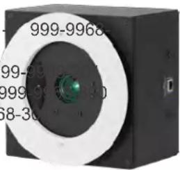
This guide describes installation and related information for the DocCAM 20 HDBTceiling-mounted document camera:
■ Camera only, worldwide - 999-9968-000
■ Camera with OneLINK HDMI camera extension, North America 200
■ Camera with OneLINK HDMI camera extension, Europe/UK – 999-
■ Camera with OneLINK Bridge A/V interface, North America – 999
■ Camera with OneLINK BridgeA/V interface, Europe/UK – 999-9968-30
natural_image
Close-up of a black rectangular electronic device with a circular lens and green lens, no visible text or symbols.What's in this Guide
This guide covers:
■ Unpacking the camera
■ Tips for a successful installation
■ Information on mounting and connecting the camera
■ Camera power-on
Complete product information is available in the Integrator's Complete Guide to the DocCAM 20 HDBT Ceiling-Mounted Document Camera.
Download manuals, dimensional drawings, and other information from www.vaddio.com/support.
Features
■ Exmor® 1/2.8 type, high-speed, low-noise image sensor for 2.38 megapixels total, full HD (native 1080p/60)
■ 20x optical zoom with horizontal field of view from 60° (wide end) to 3.3° (tele end)
■ Low-power laser pointer for centering
■ Superior low-light performance (0.4 Lux)
■ Web interface for remote administration and operation, integration-ready Telnet and serial RS-232 control, presenter-friendly IR remote control
■ Use with a OneLINK device for power, video, and control:
OneLINK HDMI – uncompressed HDMI video, bidirectional RS-232 connectivity for camera control via third-party equipment, passes IP stream from the camera
OneLINK Bridge – OneLINK HDMI capabilities plus uncompressed USB 3.0 streaming, HD-SDI output, and audio routed up to the camera and injected into the IP stream
Camera assembly numbers 998-9968-001 and 998-9968-100:
Class 1 Laser Product (IEC 60825-1:2014)
This product contains a Class 3 laser.
Unpacking the Camera
Note
This camera is shipped with a mounting kit for use in suspended acoustic tile ceilings. If you the camera in a hard ceiling (such as gypsum board), you will need mounting kit 998-2225-152.
Make sure you receive all the items you expected.
DocCAM 20 HDBT, camera only
999-9968-000 - worldwide
Note
No power option is provided with this kit. The PoE- mid-span power injector part numbers 451-0800-055 (North America) and 451-0800-155 (Europe and UK) are compatible with this camera. OneLINK devices are also compatible, and more flexibility in installation.
natural_image
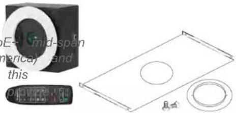
Technical illustration of a mechanical component with circular holes and a small inset view (no text or symbols)■ DocCAM 20 HDBT camera
■ Trim ring with mounting screws
■ Tile support brace
■ IR remote
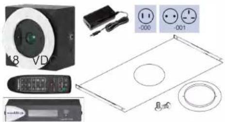
DocCAM 20 HDBT with OneLINK HDMI
999-9968-200 - North America
999-9968-201 – Europe/UK
■ DocCAM 20 HDBT camera
■ OneLINK HDMI Receiver kit – includes receiver, power supply and AC cord set(s)
■ Trim ring with mounting screws
■ Tile support brace
■ IR remote
natural_image
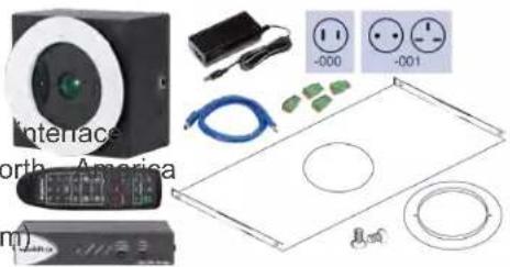
Product line drawings of electronic devices including a CD, remote control, and display panels (no text or symbols)DocCAM 20 HDBT with OneLINK Bridge
999-9968-300 - North America
999-9968-301 - Europe/UK
■ DocCAM 20 HDBT camera
■ OneLINK Bridge AV Interface kit – includes AV Interface 48 VDC power supply and AC cord set for North America
■ 3-position Phoenix-type connectors (qty. 4)
■ USB 3.0 cable, type A to type B, 6 ft (1.8
■ Trim ring with mounting screws
■ Tile support brace
■ IR remote
natural_image
Product display panel with electronic devices, wires, and circular components (no readable text or symbols)A Quick Look at the Camera
The DocCAM 20 HDBT ceiling-mounted document camera is designed for recessed mounting. The features of interest during installation are not visible after the installation is complete.
Camera assembly numbers 998-9968-001 and 998-9968-100:
Class 1 Laser Product (IEC 60825-1:2014)
Camera assembly numbers 998-9968-001 and 998-9968-100:
Note
This product contains a Class 1, 650 nm red laser pointer.
This product contains a Class 3 (5 mw) 650 nm red laser which produces visible laser radiation direct eye exposure. Do not look at the laser aperture during camera operation.
All DocCAM 20 HDBT part numbers:
Use of controls or adjustments or performance of procedures other than those specified herein may in hazardous laser radiation exposure.
Features of Interest During Installation
■ Camera enclosure - 8 x 8 x 5.1 inches (20.3 x 20.3 x 12.9 cm).
- Bezel ring – Extends 0.5 inch from the front face of the camera enclosure; includes threaded holes to attach the trim ring.
- OneLINK/HDBaseT connector – For power and all connectivity. When installed, the connector side points in the direction that the top of the document or other camera subject will face.
- Fasteners for conduit box – For installations that require all cabling to be routed through conduit. The conduit box is not supplied with this product.
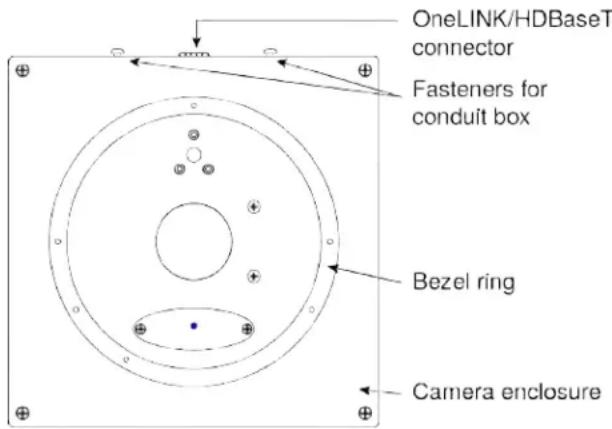
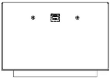
Connector Panel
The DocCAM 20 HDBT has one connector, the OneLINK/HDBaseT connector. When installed, the connector points in the direction of the top of the document or other camera subject – usually audience.
The camera has no physical switches. Hardware configuration is via the web interface.
This is it: The Art of Easy.
natural_image
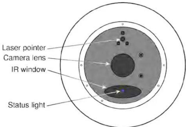
Simple line drawing of a monitor with two small icons at the top (no text or symbols)Features of Interest During Operation
In a typical installation, only the items inside the bezel ring are visible.
■ Camera lens - 20x optical zoom lens for crisp detail.
- Laser pointer – Shows where the camera image is centered. Use the remote to turn on the laser pointer.
- IR window – Sensors in the camera face receive signals from the remote. Point the remote toward the camera; precision is not necessary.
■ Status light – The multicolored LED indicates the camera's current state.
Laser controls are available to remote operators using the web interface. Keep your eyes out of path.
Installing the Camera
This section covers:
■ Connections and pre-installation functional check
■ Selecting the location for the camera
■ Preparing the ceiling
■ Installing the camera
Don't Void Your Warranty!
Caution
This product is for indoor use. Do not install it outdoors or in a humid environment without the protective enclosure. Do not allow it to come into contact with any liquid.
Do not install or operate this product if it has been dropped, damaged, or exposed to liquids. It is things happen, return it to Vaddio for safety and functional testing.
Use the power supply, power injector, or camera extension device included with or recommended with this product. For products with power supplies, using the wrong power supply will void the and could create unsafe operating conditions or damage the product. Note that power supplies for products may look nearly identical – always check the label for the output voltage.
Cabling Notes
Use Cat-5e or better cable and standard RJ-45 connectors (568B termination). We recommend usir quality connectors and a high-quality crimping tool.
Caution
Check Cat-5 cables for continuity before using them. Using the wrong pin-out may damage the c system and void the warranty.
Note
Use standard RJ-45 connectors and a good crimping tool. Do not use pass-through RJ-45 connec Poorly terminated cables can damage the connectors on the product, cause intermittent connections, degrade signal quality. Test cable pin-outs and continuity before connecting them.
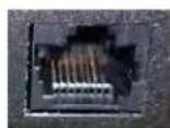
Intact - will make reliable conta with cable connector
Damaged - Bent contact fingers will NOT make reliable contact with cable connector

Pro Tip
To prevent tragic mishaps, label both ends of every cable.
Pre-Installation Functional Check
Before you install the camera, verify that it powers up and sends video. Referring to the basic diagrams, connect the camera and verify that video is available on the connected display.
When you have verified that the camera operates properly, disconnect it and continue with the in
Camera assembly numbers 998-9968-001 and 998-9968-100:
Note
This product contains a Class 1, 650 nm red laser pointer.
This product contains a Class 3 laser.
All DocCAM 20 HDBT part numbers:
Use of controls or adjustments or performance of procedures other than those specified herein may in hazardous laser radiation exposure.
The diagram below shows basic connections with a OneLINK Bridge AV Interface providing camera control, and video from the camera to other devices.
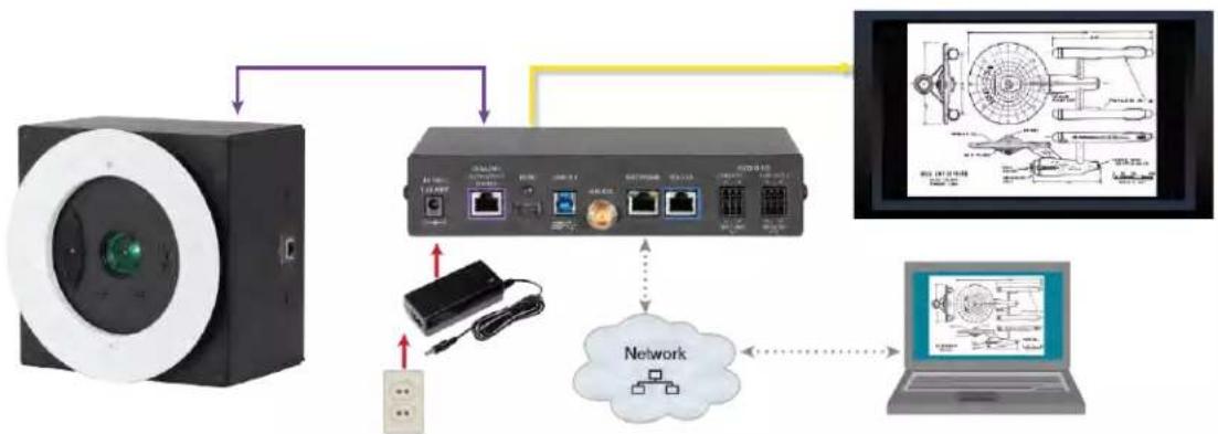
flowchart
graph TD
    A["Camera"] --> B["Network Device"]
    B --> C["Laptop"]
    B --> D["Hardware Interface"]
    D --> E["Computer Panel"]
    B --> F["User Interface"]
    F --> G["Device Icon"]
    style A fill:#f9f,stroke:#333
    style B fill:#ccf,stroke:#333
    style C fill:#cfc,stroke:#333
    style D fill:#fcc,stroke:#333
    style E fill:#ffc,stroke:#333
    style F fill:#cff,stroke:#333
    style G fill:#fcf,stroke:#333
Note
The OneLINK device is recommended but not required; the camera can be connected directly to party device with a PoE+ power injector (not provided). PoE+ mid-span power injector part number 0800-055 (North America) and 451-0800-155 (Europe and UK) are compatible with this camera.
Options for Power and Other Connections
Connect the camera to a OneLINK HDMI or a OneLINK Bridge AV Interface - a single Cat-better) cable provides power to the camera, along with HDBaseT network and video connectivity. I video output, and RS-232 control are connected at the OneLINK device. The OneLINK Bridge also provides audio connections.
Use a PoE+ power injector – Connect to a third-party control device through a PoE+ power injector (not provided). Power injector part numbers 451-0800-055 (North America) and 451-0800-155 (Europe and are compatible with this camera.
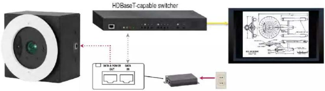
flowchart
graph TD
    A["HDBase T-capable switcher"] --> B["Switch"]
    B --> C["Screen with 3D mechanical diagram"]
    C --> D["Data IN"]
    D --> E["Data & Power Out"]
    E --> F["Output"]
About Installation Height and Viewing Area
The camera may be installed in a ceiling up to 30 ft (9.1 m) high, depending on the desired
When installed in a 9 ft (2.75 m) ceiling, such as a small classroom:
■ Minimum viewing area is smaller than a business card
■ Maximum viewing area is nearly 7 ft x 4 ft (over 2 m x 1 m)
When installed in a 30 ft (9.1 m) ceiling, such as a large lecture hall:
■ Minimum viewing area is smaller than a sheet of letter-size or A4 paper
■ Maximum viewing area is over 30 ft x 17 ft (over 9 x 5 m)
The Image Size Calculator on our website can help you to determine the minimum and maximum areas with more precision.
Selecting the Installation Area
The DocCAM 20 HDBT can be installed in a suspended acoustic tile ceiling or in a wood or Total installed weight is roughly 5.1 lbs (2.3 kg).
Note
All above-ceiling work must conform to local building codes and should be performed by qualified personnel.
-
Use the plumb line to determine the ideal camera location, centered above the surface where documents or other objects will be placed, and mark the desired center.
-
Determine the exact alignment of the camera with respect to the intended subject.
Note
The image cannot be rotated. If installing in a hard ceiling, the camera cannot be rotated aft installation.
- Verify that the area above the ceiling where the camera is to be installed is clear of obstru provides enough room for the camera enclosure:
■ 8 inch by 8 inch (20.3 cm x 20.3 cm) footprint, aligned to the work surface where the camera's subject is placed
■ Minimum 5.6 inches of clear space above the opening to maneuver the camera into place
Things You Will Need for the Installation
Before you start, be sure you have what you need:
■ Access to the area above the ceiling
■ Plumb line
■ Pencil
■ Appropriate tools for cutting a hole in the ceiling
■ #2 Phillips screwdriver
■ Conduit box, if required
■ Mounting kit 998-2225-152, if installing in a gypsum board (drywall) or other non-suspended ceiling
Installing the Camera in a Suspended Tile Ceiling
The camera is shipped with the ceiling mount for this type of installation.
The camera is mounted from above the ceiling, through a round hole, with only the bezel and inside it accessible from below. The camera rests on a support plate that distributes its weight at ceiling tile; the support plate may also be suspended. A trim ring conceals the camera bezel and adjacent portion of the ceiling tile.
Preparing the Tile Ceiling
Note
All above-ceiling work must conform to local building codes and should be performed by qualified personnel.
- Remove the ceiling tile where the camera will be mounted.
- Trace a 6.25 in. (15.9 cm) circle for the camera opening on the front side of the tile. You support brace as a template.
- Cut the camera opening.
- Ensure that the camera's bezel ring fits into the opening. The bezel ring stands out 0.5 in from the camera face.
- Place the tile back in the ceiling grid.
- Place the tile support brace above the tile, aligning it to the hole in the tile.
- Secure the tile support brace to the building structure using appropriate hardware such as Chip "Speed Connect Hardware Kit," part number CMSHDW. The ends have holes to accommodate six wires.
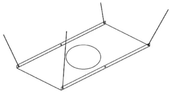
natural_image
Pure geometric diagram of a rectangular frame with an oval cutout and vertical lines, no text or symbols present.Completing the Installation in a Tile Ceiling
- Connect the camera cable to the camera, routing it through a conduit box if required.
- If using conduit, attach the conduit box to the camera enclosure using the threaded inserts of side of the cable connector.
- Seat the camera in place, with the bezel ring in the opening.
- Rotate the camera so that the cable connector is facing the same direction as the top of the or other photographic subject.
- Secure the trim ring to the camera bezel ring using the screws provided with it.
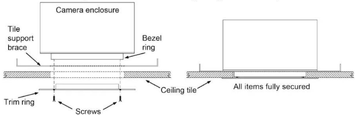
- Connect the camera cable to the OneLINK device or customer-provided PoE+ power injector. Note
After the camera is powered on, check the image and rotate the camera as needed to align it.
Installing the Camera in a Hard Ceiling
You will need mounting kit 998-2225-152 to install the camera in a gypsum board (drywall) or w This mounting kit is not included with the camera.
The camera is raised into place through a square hole in the ceiling, and attached from below mounting plates. A large trim ring conceals the portion of the camera enclosure outside the beze camera mounting plates.
Preparing the Hard Ceiling
Follow these steps to mount the camera in a gypsum board or other non-suspended ceiling using Ceiling Mounting Kit 998-2225-152.
Note
All above-ceiling work must conform to local building codes and should be performed by qualified personnel.
- Determine the exact alignment of the camera with respect to the subject. The camera face with the connector must point in the same direction as top of the document or other camera subject.
Note
The image cannot be rotated. Ensure that the camera opening is aligned precisely.
-
Trace a square, 8.125 x 8.125 inch (20.7 x 20.7 cm), for the camera
-
Cut the camera opening.
Completing the Installation in a Hard Ceiling
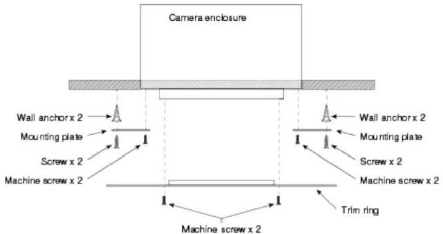
- Attach the mounting plates to the camera with the black machine screws.
- Lift the camera into place and mark the locations to drill into the ceiling.
- Drill the holes and install the screw anchors.
- Connect the camera cable to the camera, routing it through a conduit box if required.
- Lift the camera into place and secure it with the 1 1/4 in. screws.
- Attach the trim ring to the camera's bezel ring with the white machine screws.
- Connect the camera cable to the OneLINK device or customer-provided PoE+ power injector.
natural_image
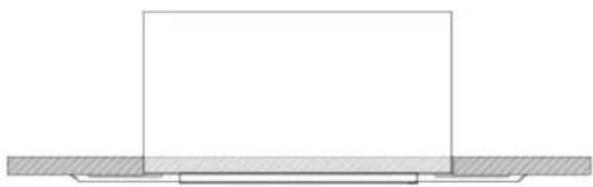
Pure technical diagram showing a rectangular block resting on a hatched base (no text or symbols)Powering Up the Camera
Connect power to the OneLINK device or PoE+ power injector that supplies power and connectivit camera.
Note
Wait until the camera finishes initializing before trying to operate or control it.
The camera will take a few seconds to initialize. When the camera is ready, its status light is point, video is available and the camera is ready to accept control information.
Camera assembly numbers 998-9968-001 and 998-9968-100:
Note
This product contains a Class 1, 650 nm red laser pointer.
This product contains a Class 3 (5 mw) 650 nm red laser which produces visible laser radiation direct eye exposure. Do not look at the laser aperture during camera operation.
All DocCAM 20 HDBT part numbers:
Use of controls or adjustments or performance of procedures other than those specified herein may in hazardous laser radiation exposure.
Laser controls are available to remote operators using the web interface. Keep your eyes out of path.
The light in the camera's face indicates its current state.
Note
By default, the camera's status light is active during normal operation; however, it can be configured to remain off when the camera is powered up. The camera may be sending video even if the incn off.
■ Blue: Normal operation (blinks off momentarily when the camera receives a command from the remote)
■ Purple: In standby mode or booting
- Yellow: Firmware update in progress – overrides status light configuration
Camera assembly numbers 998-9968-001 and 998-9968-100:
Note
This product contains a Class 1, 650 nm red laser pointer.
This product contains a Class 3 (5 mw) 650 nm red laser which produces visible laser radiation direct eye exposure. Do not look at the laser aperture during camera operation.
All DocCAM 20 HDBT part numbers:
The camera is now ready to configure and use. This information is available in the Integrator's Complete
Guide to the DocCAM 20 HDBTCeiling-Mounted Document Camera. It is also included in theConfiguration and Administration Guide for the DocCAM 20 HDBT Ceiling-Mounted Document Camera, which covers only configuring and operating the camera and system administration.
Compliance Statements and Declarations of Conformity
Camera assembly numbers 998-9968-001 and 998-9968-100:
Camera assembly numbers 998-9968-001 and 998-9968-100:
Class 1 Laser Product (IEC 60825-1:2014)
This product contains a Class 3 laser.
All camera assemblies
Compliance testing was performed to the following regulations:
| FCC Part 15 (15.107, 15.109), Subpart B Class A | |
| ICES-003, Issue 54: 2012 Class A | |
| EMC Directive 2014/30/EU Class A | |
| EN 55032: 2015 Class A | |
| EN 55024: November 2010 Class A | |
| KN24 2008 (CISPR 24: 1997 + A1: 2000 + A2: 2002) Class A | |
Camera assembly numbers 998-9968-001 and 998-9968-100:
| IEC 60950-1:2005 (2nd Edition); Am 1: 2009 + Am 2: 2013 Safety |
| EN 60950-1: 2006 + A11: 2009 + A1: 2010 + A12: 2011 + A2: 2013 Safety |
| IEC 60825-1: 2014 (3rd Edition) Safety |
FCC Part 15 Compliance
This equipment has been tested and found to comply with the limits for a Class A digital device Part 15, Subpart B, of the FCC Rules. These limits are designed to provide reasonable protection harmful interference when the equipment is operated in a commercial environment. This equipment generates, uses, and can radiate radio frequency energy and, if not installed and used in accordance with the instruction manual, may cause harmful interference to radio communications. Operation of this equipment in a residential area is likely to cause harmful interference in which case the user will to correct the interference at his/her own expense.
Operation is subject to the following two conditions: (1) This device may not cause interference, and (2) This device must accept any interference including interference that may cause undesired operation of the device.
Changes or modifications not expressly approved by Vaddio can affect emission compliance and could void the user's authority to operate this equipment.
ICES-003 Compliance
This digital apparatus does not exceed the Class A limits for radio noise emissions from digital set out in the Radio Interference Regulations of the Canadian Department of Communications.
This product has been evaluated for Electromagnetic Compatibility under the EMC Directive for Emi and Immunity and meets the requirements for a Class A digital device. In a domestic environment product may cause radio interference in which case the user may be required to take adequate
Standard(s) To Which Conformity Is Declared:
CE
EMC Directive 2014/30/EU
EN 55032: 2015 Conducted and Radiated Emissions
EN 55024: November 2010 Immunity
EN 61000-4-2: 1995 + Amendments A1: 1998 + A2: 2001 Electrostatic Discharge
EN 61000-4-3: 2006 + A1: 2008 Radiated Immunity
EN 61000-4-4: 2004 + Corrigendum 2006 Electrical Fast Transients
EN 61000-4-5: 2006 Surge Immunity
EN 61000-4-6: 2009 Conducted Immunity
EN 61000-4-8: 2010 Power Frequency Magnetic Field
EN 61000-4-11: 2004
Voltage Dips, Interrupts and Fluctuations
KN24 2008 (CISPR 24: 1997 + A1: 2000 + A2: 2002) IT Immunity Characteristics
EN 61000-4-2 Electrostatic Discharge
EN 61000-4-3 Radiated Immunity
EN 61000-4-4 Electrical Fast Transients
EN 61000-4-5 Surge Immunity
EN 61000-4-6 Conducted Immunity
EN 61000-4-8 Power Frequency Magnetic Field
EN 61000-4-11
Voltage Dips, Interrupts and Fluctuations
Camera assembly numbers 998-9968-001 and 998-9968-100:
IEC 60950-1: 2005 (2nd Edition); Am 1: 2009 + Am 2: 2013
Camera assembly numbers 998-9968-001 and 998-9968-100:
EN 60950-1: 2006 + A11: 2009 + A1: 2010 + ASafet2011 + A2: 2013
Camera assembly numbers 998-9968-001 and 998-9968-100:
IEC 60825-1: 2014 (3rd Edition)
Safety
Camera assembly number 998-9968-000 only: This product has not been evaluated for compliance with CE safety requirements.
Warranty Information
See Vaddio Warranty, Service and Return Policies posted on support.vaddio.com for complete details.
Hardware* warranty: Two (2) year limited warranty on all parts and labor for Vaddio manufactured
products. Vaddio warrants its manufactured products against defects in materials and workmanship for period of two years from the day of purchase, to the original purchaser, if Vaddio receives notice defects during the warranty. Vaddio, at its option, will repair or replace products that prove to be defective. Vaddio manufactures its hardware products from parts and components that are new or equivalent to new in accordance with industry standard practices.
Exclusions: The above warranty shall not apply to defects resulting from improper or inadequate maintenance by the customer, customers applied software or interfacing, unauthorized modifications or misuse, mishandling, operation outside the normal environmental specifications for the product, use of incorrect power supply, modified power supply or improper site operation and maintenance. OEM and special order products manufactured by other companies are excluded and are covered by the manufacturer's warranty.
Vaddio Customer Service: Vaddio will test, repair, or replace the product or products without charge if the
unit is under warranty. If the product is out of warranty, Vaddio will test then repair the product products. The cost of parts and labor charge will be estimated by a technician and confirmed by customer prior to repair. All components must be returned for testing as a complete unit. Vaddio will accept responsibility for shipment after it has left the premises.
Vaddio Technical Support: Vaddio technicians will determine and discuss with the customer the criteria
for repair costs and/or replacement. Vaddio Technical Support can be contacted by email at support@vaddio.com or by phone at one of the phone numbers listed on support.vaddio.com.
Return Material Authorization (RMA) number: Before returning a product for repair or replacement
request an RMA from Vaddio's technical support. Provide the technician with a return phone number mail address, shipping address, product serial numbers and original purchase order number. Describe reason for repairs or returns as well as the date of purchase. See the General RMA Terms ar section for more information. RMAs are valid for 30 days and will be issued to Vaddio dealers users must return products through Vaddio dealers. Include the assigned RMA number in all correspondence with Vaddio. Write the assigned RMA number clearly on the shipping label of the returning the product. All products returned for credit are subject to a restocking charge without exception. Special order product are not returnable.
Voided warranty: The warranty does not apply if the original serial number has been removed or if the
product has been disassembled or damaged through misuse, accident, modifications, use of incorrect power supply, use of a modified power supply or unauthorized repair.
Shipping and handling: Vaddio will not pay for inbound shipping transportation or insurance charges or
accept any responsibility for laws and ordinances from inbound transit. Vaddio will pay for outbound shipping, transportation, and insurance charges for all items under warranty but will not assume responsibility for loss and/or damage by the outbound freight carrier. If the return shipment appears damaged, retain the original boxes and packing material for inspection by the carrier. Contact your immediately.
Products not under warranty: Payment arrangements are required before outbound shipment for all out of warranty products.
Index
A
anatomy of the camera 3-5
B
behavior on power-up 13
C
cable connector 4, 6
camera power 8
capabilities 1
colors of the status light 14
connection example 7-8
connector identification 3
D
damage, preventing 6
|
indicator light 5, 14
location 5
installation requirements 9-11
installation, typical 7, 11-12
in gypsum board ceiling 12
in tile ceiling 11
L
laser pointer 5
location 5
location of connector 4
M
mounting kit for hard ceilings 10-11
0
OneLINK 7-8
P
packing lists 2
PoE+ power 8
power 8, 13
on and off 13
options 8
product capabilities 1
product returns and repairs 17
R
requirements, installation 9-11
RJ-45 connector 6
S
safety requirements 3, 6, 13-14
site requirements 9
status light, meanings of colors 14
structural requirements 9-11
T
typical installation 7, 11-12
in gypsum board ceiling 12
in tile ceiling 11
W
warranty 6, 17
Vaddio is a brand of Milestone AV Technologies · www.vaddio.com · Phone 800.572.2011 /
+1.763.971.4400 · Fax +1.763.971.4464 · Email info@vaddio.com
Visit us at support.vaddio.com for firmware updates, specifications, drawings, manuals, technical support information, and more. Vaddio, RoboSHOT, and OneLINK are trademarks or registered trademarks of Milestone AV Technologies. HDBaseT™ and the HDBaseT Alliance logo are trademarks of the HDBE Alliance. Exmor® is a trademark of Sony Corporation. All other brand names or marks are used identification purposes and are trademarks of their respective owners. In British Columbia, Milestone Technologies ULC carries on business as MAVT Milestone AV Technologies ULC.
©2018 Milestone AV Technologies
vaddio®