TM7553 - Phone LEGRAND - Free user manual and instructions
Find the device manual for free TM7553 LEGRAND in PDF.

| Product Type | DECT Cordless Phone |
| Brand | Legrand |
| Model | TM7553 |
| Dimensions (Handset) | Approx. 165 x 50 x 27 mm |
| Weight (Handset) | Approx. 110 g |
| Power Supply | 2 x AAA NiMH rechargeable batteries (included) or mains adapter (5V DC) |
| Standby Time | Up to 100 hours |
| Talk Time | Up to 10 hours |
| Range (Indoor) | Up to 50 meters |
| Range (Outdoor) | Up to 300 meters |
| Display | Backlit LCD, 1.8 inch, monochrome |
| Phonebook Capacity | Up to 100 entries |
| Caller ID | Yes (requires network subscription) |
| Speakerphone | Yes, hands-free function |
| Intercom | Yes, between handsets (multi-handset capable) |
| Ringtones | 10 polyphonic ringtones |
| Maintenance | Clean with a soft, dry cloth. Do not use abrasive or chemical cleaners. |
| Safety Precautions | Use only the provided adapter and batteries. Do not expose to water or extreme temperatures. |
| Spare Parts / Repairability | Replacement batteries and charging base available. Device is not user-serviceable beyond battery replacement. |
| General Information | Designed for home or office use. Compliant with DECT standards. CE marked. |
Frequently Asked Questions - TM7553 LEGRAND
User questions about TM7553 LEGRAND
0 question about this device. Answer the ones you know or ask your own.
Ask a new question about this device
Download the instructions for your Phone in PDF format for free! Find your manual TM7553 - LEGRAND and take your electronic device back in hand. On this page are published all the documents necessary for the use of your device. TM7553 by LEGRAND.
USER MANUAL TM7553 LEGRAND
The On-Q/Legrand 4 X 10 Punchdown Telecom Modules (P/N TM7553 and TM7554 as shown in Figure 1) are members of our flexible family of Telephone Distribution Modules, each of which is designed to more closely match homeowner needs.
2. DESCRIPTION
The 4 X 10 Punchdown Telecom Modules distribute four incoming telephone lines to as many as 10 locations throughout the home (see Figure 2). The P/N TM7554 version also includes an RJ-31x security system interface. Both versions have the following features:
• 110 punchdown style connectors for user friendly configuration
- All ports wired to meet TIA 568A specifications
• Accepts four incoming telephone lines
- Flexible distribution to 10 telephone locations
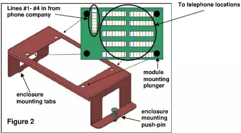
- Single bay bracket (P/N 364890-01) included for installation in On-Q style enclosure (see Figure 2)
- 50 microns gold plated contact points on RJ-31x interface port (TM7554 only)
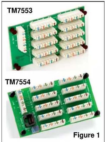
natural_image
Two green circuit boards labeled TM7553 and TM7554, showing various components and connectors (no readable text or symbols beyond labels)3. INSTALLATION
A. MOUNT THE 4 X 10 PUNCHDOWN TELECOM MODULE INTO THE ENCLOSURE
- Pull out the plungers located at each corner of the 4 X 10 Telecom Module and insert the module into the included single bay bracket (see Figure 2), depressing the plungers to secure the module to the bracket.
- Insert the bracket into the On-Q style enclosure by inserting the tabs on the bracket into the slots on the left hand side of the enclosure and securing the bracket with the push-pin on the right end of the bracket.
B. TERMINATE WIRING
NOTE: All wiring should be terminated to the T568A wiring standard as shown in Figure 3.
- Terminate the incoming Cat 5e line from the telephone company NID to the 110 style punchdown connector that is labeled "LINE IN 1,2,3,4".
- Terminate each Cat 5e line (up to 10 total) that will be used for each voice jack location to the 110 style punchdown connectors that are labeled "OUTLET LOCATIONS".

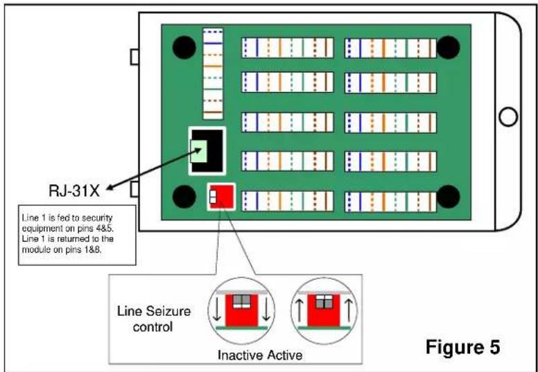
C. TERMINATE AND CONFIGURE RJ-31X LINE SEIZURE (TM7554 ONLY)
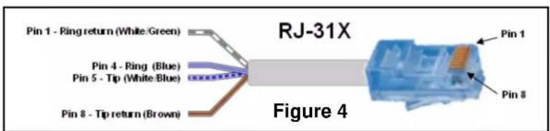
NOTE: The following steps MUST be followed to use the Line Seizure option as shown in Figures 4 & 5.
- Terminate a patch cable with a RJ45 on one end and bare-wire connection on the other (see Figure 4). Connect the bare-wire end of the patch cable to the security system according to manufacturer's instructions. Insert the RJ45 connector end of the cable into the RJ45 jack on the module that is labeled "LINE SEIZURE".
- Activate the Line Seizure function on the module by locating the two white dip switches on the module, peeling off the protective blue tape, and moving both switches upward to the active position (see Figure 5).